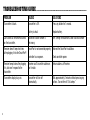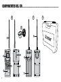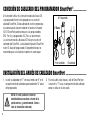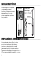
1
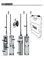
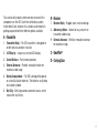
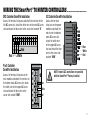
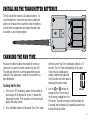
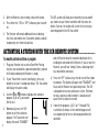
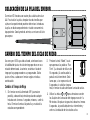
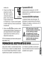
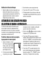
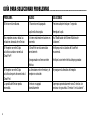
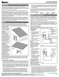
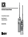
ICR
Institutional Commercial Remote
For Use with Hunter Controllers
Owner’s Manual and
Installation Instructions
®
ENGLISH/ESPAÑOL
OFF
®
MODE
ON
icr
Table of contents......................................................................................
Introduction................................................................................................................................................................... 1
ICR Components............................................................................................................................................................ 2
SmartPort ® Wiring Harness.. ........................................................................................................................................... 4
Installing the SmartPort ® Wiring Harness........................................................................................................................ 4
Wiring the SmartPort ® to Hunter Controllers................................................................................................................... 5
Typical Installations.. ...................................................................................................................................................... 6
Preparing the Transmitter for Use................................................................................................................................... 6
Installing the Transmitter Battery.................................................................................................................................... 7
Changing the Run Time.. ................................................................................................................................................. 7
Changing the Transmitter Address.. ................................................................................................................................. 8
Changing the Maximum Station Number.......................................................................................................................... 8
Preparing the Receiver for Use.. ...................................................................................................................................... 9
Changing the Receiver Address....................................................................................................................................... 9
Activating a Station with the ICR................................................................................................................................... 10
Maximizing Operating Range.. ....................................................................................................................................... 11
Troubleshooting Guide.. ................................................................................................................................................ 12
Specifications.. ............................................................................................................................................................. 13
TABLa de contenido....................................................................................
Presentación del Producto............................................................................................................................................ 15
Componentes del ICR................................................................................................................................................... 16
Conexión de Cableado del Programador SmartPort ®. ..................................................................................................... 18
Instalación del Arnés de Cableado SmartPort.. ............................................................................................................... 18
Conexión de Cableado del Programador SmartPort ®. ...................................................................................................... 19
Instalaciones Típicas.................................................................................................................................................... 20
Preparación del Emisor Antes de su Uso....................................................................................................................... 20
Colocación de la Pila del Emisor.. .................................................................................................................................. 21
Cambio del Tiempo del Ciclo de Riego.. ......................................................................................................................... 21
Modificación de la Dirección del Emisor........................................................................................................................ 22
Modificación del Número Máximo de Estaciones.. .......................................................................................................... 22
Preparación del Receptor Antes de su Uso.. .................................................................................................................. 23
Modificación de la Dirección del Receptor..................................................................................................................... 23
Activación de una Estación por Medio del Sistema de Mando a Distancia ICR................................................................. 24
Optimización de la Zona de Funcionamiento.. ................................................................................................................. 25
Guía Para Solucionar Problemas................................................................................................................................... 26
Datos Técnicos............................................................................................................................................................. 27
Introduction................................................................................................
Finally there’s an affordable remote control system designed with the commercial irrigation contractor in mind. Hunter is
pleased to introduce the Institutional Commercial Remote (ICR). This rugged remote design offers similar functionality as
our SRR remote, but with longer range capability.
With the ICR there’s no need to walk back and forth to the controller to conduct manual watering operations when doing
maintenance or repair work on your irrigation systems. Also, winterization can be done quickly and easily with one worker
instead of two.
The ICR is designed to be rugged, and water resistant. Its large LCD display and push button design makes it easy to
operate. Best of all, with an operating range from ½ to 1 mile, you’ll be able to conduct remote operations on even the
largest irrigation systems.
The following instructions provide information on installing, setting up, and operating your ICR.
ICR Components..............................................................................................
B
A
D
C
9
4
®
6
2
8
OFF
1
MODE
ON
ICR
3
5
7
This section will provide a brief overview of some of the
components on the ICR. Each item will be discussed in
further detail later, however, this section can be helpful in
getting acquainted with the different options available.
A – Transmitter
1. Transmitter Body – The ICR transmitter is designed to
be dirt tolerant and water resistant.
B – Receiver
7. Receiver Body – Rugged, water resistant design.
8. Addressing Button – Allows for easy receiver to .
transmitter addressing.
9. External Antennae – Flexible, removable antennae .
for maximum range.
2. LCD Display – Large, easy to read LCD display.
C – SmartPort®
3. Control Buttons – Push button operation.
D – Carrying Case
4. External Antennae – Flexible, removable rubber for
maximum radio range.
5. Battery Compartment – The ICR is designed to operate
on a four AA alkaline batteries. The batteries easily drop
into a battery holder.
6. Belt Clip – Belt clip provides convenient access to the
transmitter at all times.
SmartPort® Wiring Harness........................................................................
To utilize the ICR remote control system, your controller
must be equipped with a SmartPort wiring harness. This
wiring harness provides the communication port where the
ICR receiver is attached. The SmartPort can be connected to
Hunter SRC, Pro-C and ICC controllers. A SmartPort wiring
harness is provided with your ICR remote system. The
typical SmartPort location is approximately 12" below the
controller. The recommended installation procedure for this
location would be as follows:
To Controller
1/2"
Thread
Pre-assembled
Assembled
Installing the SmartPort Wiring Harness.........................................
1. Install a ½" female threaded “Tee” in the field wiring
conduit approximately 12" below the controller.
NOTE: The harness may be installed outdoors
by bringing the conduit through an exterior
wall, then installing the appropriate fitting.
2. Feed the red, white, and blue wires of the SmartPort
through the base of the “Tee” and into the controller
wiring compartment as shown in the following figures..
NOTE: For installations where the receiver
will be installed permanently on an outside
wall, make certain that the SmartPort is the
version with an o-ring seal.
wiring the SmartPort® to hunter controllers...............................
SRC Controller SmartPort Installation
ICC Controller SmartPort Installation
Access the terminal strip area and attach the red wire to the
left AC screw slot, attach the white wire to the next AC screw
slot and attach the blue wire to the screw slot marked “R”.
Access the terminal
strip area on the power
module and attach the
red wire to the bottom
most AC screw slot,
attach the white wire
to the upper AC screw
slot and attach the blue
wire to the screw slot
marked “REM”.
AC AC R RS C MV 1
2
3
4
5
6
Blue
Red
White
Pro-C Controller
SmartPort Installation
Access the terminal strip area on the
main module and attach the red wire to
the bottom most AC screw slot, attach
the white wire to the upper AC screw
slot and attach the blue wire to the
screw slot marked “REM”.
Blue
White
Red
NOTE: Hunter ACC controllers are provided
with the SmartPort ® Factory installed.
Blue
White
Red
Typical Installations.................................................................................
Although the ICR Receiver is water
resistant, it is recommended that the
SmartPort ® connector and Receiver be
mounted indoors if it is to be left permanently mounted to the controller.
Indoor Installation
Outdoor Installation
(Temporary Connection
of Receiver Only)
Controller
Receiver
Preparing the Transmitter for Use..................................................
The ICR remote system is designed to work right out of
the box. This means that other than installing the battery,
you may choose to skip this entire section. However, we
recommend that you read it so that you can customize your
ICR to add functionality and security to your system.
Installing the Transmitter Batteries.............................................
The ICR transmitter requires 4 AA alkaline batteries. To
install the batteries. remove the two screws holding the
battery on the back of the transmitter. Drop the batteries
into the battery compartment and replace the door. Your
transmitter is now ready to operate.
Changing the Run Time...............................................................................
You have the ability to adjust the amount of time that a
station will run once it has been turned on by your ICR.
This does not affect the run time programmed into your
controller. This adjustment is made at the transmitter as
described below.
To change the Run Time:
1. If the unit is OFF (no display), power the transmitter by
pressing any of the buttons for at least 1 second then
releasing the button. The transmitter will illuminate and
display the active station.
2. Press the Mode button until the words “Run Time” along
with the current Run Time is displayed. (default is 10
minutes) The Run Time will be blinking at this point.
If more than 5 seconds go by
without a button being pressed,
the Transmitter will revert back to
displaying the active station.
3. Use the
or
buttons to
36/5*.&
change the Run Time to any of
the 8 settings ranging from 1 to
90 minutes. Then do not touch any of the buttons for
5 seconds and the display will stop blinking and return
back to the active station.
Changing the Transmitter Address...................................................
Both the ICR Transmitter and Receiver have an “address”
that they use when communicating. If the addresses do
not match, the Receiver will ignore the transmission. Your
ICR comes from the factory with both the transmitter and
Receiver address set to 0. You may change the address to
any value from 0-127 for added security. Note that if you
change the Transmitter address, the Receiver must “learn”
the new address as described in the “Preparing the Receiver
for Use” section.
To change the Transmitter address:
1. If the unit is OFF (no display), power the Transmitter up
by pressing any of the buttons for at least 1 second then
releasing the button. The Transmitter will illuminate the
active station.
2. Press the Mode button until the word “Address” appears
on the display. The address will be blinking at this point.
If more than 5 seconds go by
without a button being pressed,
the Transmitter will revert back to
displaying the active station.
3. Use the
or
button to
change the address to any value
"%%3&44
between 0 and 127. Then do not
touch any of the buttons for 5 seconds and the display
will stop blinking and return back to the active station.
Changing the Maximum Number of Stations..................................
Your ICR Transmitter comes from the factory with the
maximum number of stations set to 9. This means that when
you use the
or
buttons to change the station, you
may change it to any number between 1 and 9. However, if
you have controllers with more than 9 stations you will want
to increase the maximum number of stations.
To change the Maximum Number of Stations:
1. If the unit is OFF (no display), power the Transmitter up
by pressing any of the buttons for at least 1 second then
releasing the button. The Transmitter will illuminate the
active station.
2. Press the Mode button until the
word “Max Station” appears
on the display. The maximum
number of stations will be .
blinking at this point.
provides the user with the ability to operate programs .
(A, B, C).
ACC/ACC Decoder Controllers
."945"5*0/
3. Use the
or
button
to increase or decrease the
maximum number of stations. Then do not touch any
of the buttons for 5 seconds and the display will stop
blinking and return back to the active station.
The ICR is designed to operate with two groups of Hunter
controllers:
SRC/Pro-C/ICC Controllers
The maximum number of stations from 1 to 48. The ICR also
Selecting the maximum station number 240 allows the user
to operate up to 240 stations and 18 programs (programs
are displayed with a P and program number ex: P5).
NOTE: When the ICR transmitter is set in
the ACC mode (240 stations), the ICR will
only communicate with ACC controllers. To
operate other Hunter controllers (SRC, Pro-C,
and ICC) with your remote, the transmitter
max stations needs to be set to a number from
1 to 48 stations.
Preparing the Receiver for Use.............................................................
As stated earlier, your ICR is designed to work right out of
the box. If you have decided to change your Transmitter
address as described in the previous section, you must allow
the Receiver to “learn” this new address. Once learned, the
only way to remove the address from the Receiver memory
is to learn a different address. This can be done by following
the simple steps outlined below.
Changing the Receiver Address
1. Hold down the single button on the face of the
Receiver while you are plugging it into an active
SmartPort ® wiring harness (one connected to a
powered controller). When this is done the .
Receiver will beep 4 times.
2. After the Receiver starts to beep, release the button.
3. Press either the “ON” or “OFF” button on your transmitter.
4. The Receiver will beep 4 additional times indicating
that it has learned the new Transmitter address and will
respond only to it from this point on.
The ICR system will allow you to remotely turn on and off
any station on your Hunter controller with the press of a
button. Once on, the station will run for the run time you
have designated in the ICR transmitter.
Activating a Station with the ICR Remote System.......................
To remotely activate a station or program:
1. Plug your Receiver into an active SmartPort wiring
harness (one attached to a powered controller) and wait
for 2 beeps indicating the Receiver is ready.
®
2. If your Transmitter is not on (no display), press any
button for at least 1 second and release. The Transmitter
will display the active station.
3. Use the
or
buttons to display the station or
program (A,B, or C) you would
like to start.
10
4. Momentarily press the “ON”
button to start the station or
program. The Transmitter will
display the word “TRANSMIT”
45"5*0/
and will flash for about 4 seconds indicating that it is
sending the command to the Receiver. If you are near the
Receiver, you will hear it beep 2 times, indicating that it
has received the command.
5. Press the “OFF” button at any time to turn off the station
or program. The display will again read “TRANSMIT” and
flash, and the Receiver will again beep twice. The ICR
is designed to turn one station on at a time. Therefore,
turning a station on while another is already on will
cause the first station to turn off.
6. If one of the programs (A,B, C or P1 through P18)
is selected, all stations in the selected program will
run sequentially for the run time programmed in the
controller.
NOTE: The ICR remote can activate any station
on the controller whether the controller dial
is in the “System Off”, “Run” or “Run/Bypass
Sensor” modes. If a sensor device has been
wired to the controller, the ICR will not
override the sensor for manual operation.
Maximizing Operating Range..................................................................
The ICR is designed as an extended range remote that
should meet the range requirements for even the largest
irrigation systems. The maximum range of transmission will
vary from approximately ½ mile to 2 miles depending upon
the site terrain and the location of the Receiver.
Listed below are a few steps to assure that you are
getting the maximum range possible:
1. Do not install the SmartPort ® wiring harness (that the
Receiver connects to) near large sources of metal such
as power meters, water pipes, and metal siding.
3. For maximum range in all directions from the Receiver,
the Receiver antennae should be pointed straight up
(vertically). If the Receiver is mounted with its antennae
oriented horizontally, reception will be very good if the
Transmitter is on either side of the antennae, but poor if
it is facing the end of the antennae.
4. When operating the Transmitter, hold the Transmitter as
vertical as possible and turn and face the direction of the
Receiver even though it may be a long way away.
2. Do not install the SmartPort wiring harness in a
basement or underground location.
11
Troubleshooting Guide..............................................................................
PROBLEM
CAUSes
Solutions
Transmitter is blank.
Transmitter is Off..
.
Battery is dead.
Press any button for 1 second..
.
Replace battery.
Can’t access all the desired stations
on the transmitter.
Maximum station number is .
set wrong.
See “Setting the Maximum Station stations Number”
SmartPort is not connected properly.. Recheck the SmartPort installation..
Receiver doesn’t beep two times
.
after plugging it into the SmartPort®. .
Controller has no power.
Check controller power.
12
Receiver beeps twice after plugging
it in, but won’t respond to the
transmitter.
Receiver and Transmitter addresses
don’t match.
Relearn address at Receiver.
Transmitter display stays on.
Transmitter will turn off
automatically.
Wait approximately 2 minutes without pressing any
buttons. Transmitter will “fall asleep.”
Specifications.................................................................................................
Operating Specifications
Dimensions
•
Transmitter (w/o antennae): Height: 6.5".
Width: 3.25".
Depth: 1.25"
Address Range: 0-127
•
Maximum stations supported: 240
•
Run Time: 8 settings from 1 to 30 minutes
•
Range: up to 2 miles depending upon time terrain
Electrical Specifications
•
Power Source Transmitter: 4 AA alkaline batteries
•
Power Source Receiver: 24VAC, 0.050 amps
•
System Operating Frequency: 27MHz band
Receiver (w/o antennae):
Height: 6.25".
Width: 3".
Depth: 1.25"
Default Settings
Address = 0 (may be varied from 0-127)
Number of Stations = 9 (may be varied from 1-48)
Run Time: 10 minutes
13
Presentación del Producto.....................................................................
Por fin hay un sistema de mando a distancia fiable y accesible, diseñado teniendo en mente las necesidades del contratista
de la industria de riego comercial. La sociedad Hunter está satisfecha del lanzamiento del ICR, un sistema de mando a
distancia. Su diseño de alta resistencia le permite funcionabilidad similar al sistema de mando tipo SRR, pero con una
capacidad de mayor distancia.
Con el ICR no existe la necesidad de caminar de ida y regreso al programador para llevar a cabo operaciones de riego cuando
esté haciendo labores de mantenimiento o reparación de su sistema de riego. Asimismo, las actividades de preparación para
el invierno pueden implementarse rápida y fácilmente con un trabajador en lugar de dos.
El ICR está diseñado para ser de alta dureza e impermeable. Su gran pantalla LCD y su diseño de teclas de presión lo hacen
fácil de operar. Lo mejor de todo es que, con un rango de operación de ½ hasta 2 millas, dependiendo del terreno, usted
podrá ejecutar operación con control de mando, aún en los sistemas de riego más extensos.
Las siguientes indicaciones le proporcionarán la información necesaria para instalar, modificar y operar su sistema .
operativo ICR.
15
Componentes del ICR...................................................................................
B
A
D
C
9
4
®
6
2
8
OFF
1
16
MODE
ON
ICR
3
5
7
Esta sección le proporcionará un breve resumen ejecutivo
respecto a los componentes del ICR. Cada componente será
comentado con mayor detalle posteriormente, asimismo,
la presente sección le será útil para familiarizarse con las
diferentes opciones disponibles del producto.
A – Emisor
1. Cuerpo del Emisor – El Emisor ICR está diseñado para
soportar la suciedad y es impermeable.
B – Receptor
7. Cuerpo del Receptor – De alta resistencia, con diseño
impermeable.
8. Botón de Acceso – Le permite un fácil acceso al receptor
para comunicarse con el emisor.
9. Antenas Externas – Flexibles, desmontables para un
radio de acción óptimo.
2. Pantalla tipo LCD – Grande, fácil de leer
C – SmartPort®
3. Tecleado de Mando a Distancia de Presión – Fácil de
operar.
D – Caja
4. Antenas Externas – Flexibles, de goma desmontable
para un radio de acción óptimo.
5. Compartimiento de las Pilas – El diseño ICR es fácil de
operar mediante cuatro pilas alcalinas.
6. Porta- Cinturón – Le proporciona, en todo momento, un
conveniente acceso al emisor.
17
Conexión de Cableado del Programador SmartPort®....................
A fin de poder utilizar el sistema de mando a distancia ICR,
su programador Hunter está equipado con un arnés de
cableado SmartPort. Dicho cableado de arnés le proporciona
una comunicación al puerto a donde se conecta el receptor
ICR. El SmartPort puede conectarse a los programadores
SRC, Pro-C y al programador ICC. Para su conveniencia,
su sistema de mando a distancia ICR incluye un arnés de
cableado tipo SmartPort. La localización típica del SmartPort
es de 12" abajo del programador. El procedimiento que se
recomienda para la instalación respectiva es como sigue:
Al Programador
/ " Rosca
1 2
Pre-ensamblado
Ensamblado
Instalación del Arnés de Cableado SmartPort.................................
1. Instale un adaptador de “T” de rosca hembra de ½" en el
compartimiento del cableado aproximadamente 12" abajo
del programador.
NOTA: El arnés puede en el exterior
estableciendo un conducto a través de la
pared externa, y posteriormente, llevar a
cabo la instalación adecuada).
18
2. Pase los cables rojo, blanco y azul del SmartPort por
la base de la “T” hacia el compartimiento del cableado
como se indica en la ilustración.
Conexión de Cableado del Programador SmartPort®....................
Instalación SmartPort del Programador SRC
Module
Instalación SmartPort delPower
Programador
ICC
Con acceso al compartimiento de cableado, conecte el cable
rojo al primer borneo marcado AC, el blanco al borneo .
sugundo marcado AC y el azul al borneo R.
Con acceso al
compartimiento de
cableado, conecte el
cable rojo al borneo
bajo marcado AC,
el blanco al borneo
superior marcado AC y
el azul al borneo REM.
AC AC R RS C MV 1
2
3
4
5
6
Azul
Rojo
Blanco
Instalación SmartPort del
Programador Pro-C
Con acceso al compartimiento de
cableado, conecte el cable rojo al
borneo bajo marcado AC1, el blanco
al borneo superior marcado AC2 y el
azul al borneo REM.
Azul
Azul
Blanco
Rojo
NOTA: Los programadores Hunter ACC están
provistos de un SmartPort instalado de
fábrica.
Blanco
Rojo
19
Instalaciones Típicas...............................................................................
Aunque el Receptor ICR es impermeable,
se recomienda que, el conector
SmartPort ® y su Receptor sean montados
bajo techo, si es que se va a dejar
montado al programador respectivo en
forma permanente.
Instalación Interior
Instalación Exteriór
(Conexion Temporal
Únicamente del Receptor)
Programador
Receptor
Preparación del Emisor Antes de su Uso.......................................
El sistema de mando a distancia ICR está diseñado
para funcionar inmediatamente. Ello significa que,
exceptuando la colocación de las pilas, se pueden
ignorar completamente, las instrucciones que siguen.
Recomendamos, sin embargo, se lean para personalizar su
ICR y agregar la funcionabilidad y seguridad de su sistema.
20
Colocación de la Pila del Emisor.......................................................
Su emisor ICR funciona con cuatro pilas alcalinas de clase
AA. Para instalar las pilas, desplace los dos tornillos que
sujetan el compartimiento posterior del emisor. Introduzca
las pilas en dicho compartimiento e instale nuevamente la
tapa posterior. Concluyendo lo anterior, su emisor está listo
para operar.
Cambio del Tiempo DEL CICLO de Riego...............................................
Una vez que el ICR haya sido activado, usted cuenta con
la habilidad de ajustar el ciclo de riego que desea en una
estación determinada. Lo anterior, no afecta el ciclo de
riego que haya programado en su programador. Dicho
ajuste se lleva a cabo con el emisor según se indica a
continuación.
Cambios al Tiempos de Riego
1. Si el emisor no está alimentado OFF (ausencia en
pantalla), colocarlo bajo tensión pulsando cualquier
tecla durante al menos 1 segundo, entonces, suelte la
tecla. El emisor iluminará la pantalla y se activará la
estación correspondiente.
2. Presione la tecla “Mode”, hasta
que aparezcan las palabras “Run
Time”. (La duración de falla es de
10 segundos). A continuación la
36/5*.&
pantalla está intermitente. Señalamos que, si se esperan más de
5 segundos sin solicitar ninguna
tecla, el emisor visualiza de nuevo la estación activa.
3. Utilizar las teclas
y
para seleccionar uno de
los 8 ajustes de la duración del riego que van de 1 a
90 minutos. No pulsar ninguna tecla durante al menos
5 segundos, la pantalla deja de estar intermitente y
vuelve a la indicación de la estación activa.
21
Modificación de la Dirección del Emisor.......................................
El emisor y el receptor ICR poseen una “dirección” que
utilizan para comunicarse entre sí. Cuando ambas direcciones no corresponden, el receptor ignora la transmisión.
A la salida de fábrica, las dos direcciones del sistema de
mando a distancia ICR están programadas a 0. Puede dar
a la dirección un valor comprendido entre 0 y 127 para
aumentar la seguridad del sistema. Señalamos que cuando
se modifique la dirección del emisor, el receptor tendrá que
“aprender” la nueva dirección, como se especifica en el
capítulo “Preparación del Receptor Antes de Utilizarlo”.
2. Presione la tecla “Mode”, hasta que aparezcan las
palabras “Run Time”, junto con la duración del ciclo
de riego actual. (La duración
de falla es de 10 segundos). A
continuación la pantalla está
intermitente. Señalamos que, si
se esperan más de 5 segundos
sin solicitar ninguna tecla, el
"%%3&44
emisor visualiza de nuevo la
estación activa.
Para Modificar la Dirección del Emisor
3. Utilizar las teclas
y
para modificar cualquier
dirección comprendida entre los valores 0 al 127. No
pulsar ninguna tecla durante al menos 5 segundos, la
pantalla deja de estar intermitente y vuelve a la indicación de la estación activa.
1. Si el emisor se encuentra sin alimentación (pantalla
apagada), ponerlo bajo tensión pulsando cualquier
tecla durante al menos 1 segundo. Toda la pantalla
se enciende durante 1 segundo aproximadamente y a
continuación aparece el número de la estación activa.
Modificación del Número Máximo de Estaciones......................
22
El emisor ICR está ajustado en fábrica con un número
máximo de estaciones igual a 9. Ello significa que se
pueden utilizar las teclas
y
, para cambiar
el número de estaciones entre 1 y 9. Sin embargo,
si tiene programadores con más de 9 estaciones, se
puede incrementar dicho número máximo de estaciones
procediendo de la siguientes manera.
Para Modificar el Número Máximo de Estaciones
1. Si el emisor se encuentra sin alimentación OFF (pantalla apagada), ponerlo bajo tensión pulsando cualquier
tecla durante al menos 1 segundo. El emisor ilumina la estación activa.
2. Presione la tecla “Mode”, hasta
que aparezcan las palabras
“Max. Station” en la pantalla.
A continuación aparece en la
."945"5*0/
pantalla, en forma intermitente,
el número máximo de estaciones. Señalamos que, si se esperan más de 5 segundos
sin solicitar ninguna tecla, el emisor visualiza de nuevo
la estación activa.
3. Utilizar las teclas
y
para incrementar o reducir,
el número máximo de estaciones. Posteriormente, no
pulsar ninguna tecla durante al menos 5 segundos,
la pantalla deja de estar intermitente y vuelve a la
indicación de la estación activa.
El ICR está diseñado para que funcione con dos grupos de
programadores Hunter:
Programadores SRC/Pro-C/ICC
El máximo número de estaciones de 1 a 48. El ICR
proporciona además la capacidad de poner programas en
funcionamiento (A, B, C).
Programadores ACC/ACC99D de decodificadores
La selección del máximo número de estaciones, 240,
permite poner en funcionamiento hasta 240 estaciones y
18 programas (los programas se muestran con una P y el
número de programa, ej.: P5).
NOTA: Cuando el mando a distancia ICR
transmite en modo ACC (para 240 estaciones)
sólo podrá comunicarse con modelos
de programadores ACC. Para utilizar
programadores estánderes de Hunter (SRC,
Pro-C y ICC) se deberá utilizar el modo de
transmisión estándar (programado para
funcionar de 1 a 48 estaciones).
Preparación del Receptor Antes de su Uso...........................
Como ya hemos señalado, su sistema de mando a distancia
ICR, está listo para su empleo. Si ha cambiado la dirección
de su emisor del modo anteriormente descrito, el receptor
respectivo tiene que “aprender” la nueva dirección. Una vez
que el receptor haya aprendido la nueva dirección, la
única manera de borrarla consistirá en enseñarle otra
actuando de la manera siguiente:
23
Modificación de la Dirección del Receptor
2. Soltar el botón en cuanto se oiga el primer bip.
1. Mantener hundida la única tecla situada sobre la cara
delantera del receptor mientras que se conecta a un
conjunto de cables bajo tensión de un SmartPort ® (el
programador bajo tensión). Cuanto esto sucede, el
Receptor emite cuatro bips acústicos.
3. Pulsar la tecla “ON” o la tecla “OFF” de su emisor.
4. El Receptor produce 4 bips acústicos para indicar que
ha aprendido la nueva dirección del emisor y que ya no
contestará a otra distinta.
Activación de una Estación por Medio
del Sistema de Mando a Distancia ICR................................................
El sistema de mando a distancia ICR permite arrancar
o parar cualquier estación de su programador Hunter
presionando una única tecla. Una vez que se ha activado
una estación, la misma funcionará durante el ciclo de riego
programado por medio del emisor ICR.
Para Activar a distancia una estación o un programa,
hay que proceder de la manera siguiente:
1. Conectar su Receptor a un SmartPort ® activo (el programador bajo
tensión) y espere a que el mismo
emita 2 bips acústicos indicando
que el Receptor está listo.
2. Si el emisor no está alimentado
(sin pantalla), pulsar cualquier
24
45"5*0/
tecla durante al menos 1 segundo y a continuación
aparece el número de la estación activa.
3. Utilizar las teclas
y
para visualizar la estación o
el programa (A, B, o C) que desea activar.
4. Pulsar la tecla “ON” para arrancar la estación o
programa. Sobre la pantalla del emisor aparecen las palabras “ON” y “TRANSMIT” y están intermitentes durante
aproximadamente 4 segundos para indicar que se ha
transmitido la orden al receptor. El Receptor emite 2 bis
acústicos para indicar que ha recibido la orden.
5. Pulsar la tecla “OFF” en cualquier momento a fin de
parar la estación o programa que están funcionando.
Aparecen las palabras “OFF” y “TRANSMIT” en forma
intermitente, y el Receptor emite de nuevo 2 bips
acústicos. El sistema ICR ha sido diseñado para poner
una sola estación en marcha cada vez. Por consiguiente,
si se pone en marcha una estación cuando ora está ya
funcionando, esta última se parará automáticamente.
6. Si uno de los programas (A, B, C o desde el P1 al P18)
se selecciona, todas las estaciones en el programa
seleccionada arrancan en forma secuencial por el ciclo
de riego programado por el programador.
NOTA: El sistema de mando a distancia ICR puede
activar cualquier estación del programador, poco
importa que el selector giratorio se encuentra en
posición PARADO, MARCHA, o ARRANQUE / SENSOR
DE DESVIACIÓN “System off”, “Run” o “Run/
Bypass Sensor”. Si se ha conectado un captador al
programador, el sistema ICR pondrá en desviación
dicho captador, para emitir un funcionamiento
manual.
Optimización de la Zona de Funcionamiento...........................................
La funcionabilidad del ICR está diseñada con una extensa
capacidad de mando a distancia para satisfacer los
requerimientos de sistemas de riego más grandes. La
distancia máxima de la zona de funcionamiento varía entre
aproximadamente una ½ y hasta 2 millas, dependiendo de
las características del terreno y la localización del receptor.
A continuación se proporciona una lista de algunas
que se pueden adoptar para asegurar una zona de
funcionamiento más grande posible:
1. No instale la salida de cables SmartPort ® (a la que está
conectada el receptor) cerca de una masa metálica
importante, como por ejemplo un contador, una tubería
de agua, un revestimiento de aluminio.
2. No instale la salida de cables SmartPort en un sótano o
en cualquier otro lugar subterráneo.
3. Para obtener una zona de funcionamiento máxima
del Receptor en todas las direcciones, la antena del
Receptor tiene que orientarse hacia arriba (posición
vertical). Si el Receptor está instalado con posición
horizontal, la recepción será muy buena cuando el
Emisor está colocado a uno de los lados de la antena,
pero será muy mala cuando el Emisor esté enfrente del
extremo de la antena.
4. Cuando se utiliza el emisor, hay que mantenerlo lo más
vertical posible y hay que girarse hacia el Receptor
aunque se encuentre muy alejado.
25
Guía Para Solucionar Problemas..........................................................
26
Problema
Causas
Soluciones
El Emisor está en blanco.
El Transmisor está apagado..
.
La pila está descargada.
Presione cualquier tecla por 1 segundo..
.
Reemplace la pila.
No se pueden accesar todas las
estaciones deseadas el en Emisor.
El número máximo de estaciones es
incorrecto.
Vea “Modificación del Número Máximo de
Estaciones”.
El Receptor no emite 2 bips
acústicos cuando se conecta al
SmartPort®.
El SmartPort no está conectado
correctamente..
.
El programador no tiene corriente
eléctrica.
Verifique que la instalación del SmartPort .
sea correcta..
.
Verifique la corriente eléctrica del programador.
El Receptor no emite 2 bips
acústicos después de conectarlo al
SmartPort.
Las direcciones entre el emisor y el
receptor no coinciden.
Re-programe la dirección del receptor.
La pantalla del Emisor queda
encendida.
El emisor se apagará
automáticamente.
Espere por aproximadamente unos 2 minutos sin
presionar ninguna tecla. El emisor “se irá a dormir”.
Datos Técnicos................................................................................................
Especificaciones de Operación
Dimensiones
•
Emisor (sin antena): Altura: 16.5 cm.
Ancho: 8.26 cm.
Profundidad: 3.17 cm
Direcciones: 0-127
•
Número máximo posible de estaciones: 240
•
Tiempos de Riego: 8 reglajes de 1 a 30 minutos
•
Alcance: hasta 2 millas dependiendo del terreno
Especificaciones Eléctricas
•
Alimentación del emisor: 4 pilas alcalinas AA
•
Alimentación del receptor: 24VAC, .05 amperes
•
Frecuencia de funcionamiento del sistema: .
una banda de 27 Mhz
Emisor (sin antena): Altura: 15.87 cm.
Ancho: 7.6 cm.
Profundidad: 3.17 cm
Reglaje por falla
•
Dirección = 0 (puede ajustarse entre 0 y 127)
•
Número de estaciones = 9 (puede ajustare entre 1 a 48)
•
Tiempos del ciclo de Riego = 10 minutos
27
FCC Compliance Notice................................................................................
This device does not require an FCC License. The ICR Receiver complies with the limits of Part 15 of the FCC Rules. The
Transmitter complies with Part 95 Subpart E of the FCC Rules. These limits are designed to provide reasonable protection
against harmful interference when this equipment is operated in a commercial environment.
Este sistema no requiere de ninguna licencia de la FCC. El receptor ICR cumple con los límites especificados por la Sección
15 de las Reglas correspondientes de la FCC. El emisor cumple con los estándares definidos en la parte 95, sub-parte
E de las Reglas de la FCC. Estos límites se han designado para proporcionar una protección razonable contra cualquier
interferencia cuando el equipo y el sistema estén funcionando en un medio ambiente comercial.
Hunter Industries Incorporated • The Irrigation Innovators
1940 Diamond Street • San Marcos, California 92078
www.HunterIndustries.com • www.HunterRiego.com
© 2007 Hunter Industries Incorporated
P/N 700914
LIT-357
4/07