1
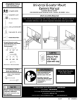
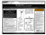
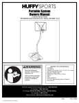
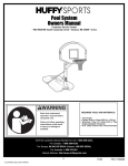
A Huffy Company
Customer Service Center
N53 W24700 South Corporate Circle
Sussex, WI 53089
U.S.A.
WRITE IN YOUR MODEL NUMBER:
Universal Elevator Mount Owners Manual
SAFETY INSTRUCTIONS
FAILURE TO FOLLOW THESE SAFETY INSTRUCTIONS MAY
RESULT IN SERIOUS INJURY,
PROPERTY DAMAGE AND WILL VOID WARRANTY.
Owner must ensure that all players know and follow these
rules for safe operation of the unit.
To ensure safety, do not attempt to assemble this system without
following the instructions carefully. Check entire box and inside all
packing material for parts. Before beginning assembly, read the
instructions and identify parts using the hardware identifier and parts
list in this document. Proper and complete assembly, use and
supervision are essential for proper operation and to reduce the risk of
accident or injury. A high probability of serious injury exists if this
system is not installed, maintained, and operated properly.
• This equipment is intended for home recreational use only and NOT
excessive competitive play.
• Read and understand the warning label enclosed with hardware. It is
the responsibility of the customer to mount this label. It should be
Required Tools and
Materials:
NOTE: Due to various mounting
methods, additional tools and
materials may be required.
•
•
•
•
Two People
Tape Measure
Pencil
Wrenches: (Two) 7/16”, 1/2”,
9/16”, 3/4”
or Large and Small Adjustable
Wrenches
• Step Ladder 8 ft. (2.4 m)
• Drill & Bit (3/8”)
• Carpenter Level
affixed to the pole, wall, or door near playing area, at a height between
4-6 feet (1.2 -1.8 m) above ground level and in a location visible to all
players.
• During assembly, if using a ladder use extreme caution. Two people are
by misuse and/or
recommended for this operation.
not following instructions.
• If technical assistance is required, contact Huffy Sports.
• Adult supervision is recommended when adjusting height.
IMPORTANT!
Most injuries are caused
Use caution when using this unit.
Have questions...don’t go back to the store!
We appreciate your purchasing one of our many fine products. We are sure that you will be very satisfied with your selection. Although
great care and effort have been taken, occasionally problems may occur. To ensure prompt and correct handling of any problems, or to
answer any questions, please contact our Toll-Free Customer Service Number listed below. Service will be quicker if you have your
Model Number (found on carton) and assembly instructions ready when calling. PLEASE WRITE YOUR MODEL NUMBER IN
THE SPACE PROVIDED ABOVE.
Toll-Free Customer Service Number for U.S: 1-800-558-5234 and Canada Only: 1-800-284-8339
Internet Address: http://www.huffysports.com
printed on recycled paper
1
10/01
P/N 211125A
WARNING
FAILURE TO FOLLOW THESE WARNINGS MAY RESULT
IN SERIOUS INJURY AND/OR PROPERTY DAMAGE.
Owner must ensure that all players know and
follow these rules for safe operation of the unit.
See instruction manual for proper installation and
maintenance.
Use caution when performing dunk type activities on this unit.
Do not hang from any part of unit, including backboard,
support braces, rim or net.
Keep pole top covered with cap at all times.
Do not slide, climb, shake or play on pole.
Keep organic material away from pole base. Grass, litter, etc.
could cause corrosion and/or deterioration.
Check pole system for signs of corrosion (rust, pitting,
chipping) and repaint with exterior enamel paint. If
rust has penetrated through steel anywhere, replace pole
immediately.
Check unit before each use for loose hardware, excessive
wear and signs of corrosion and repair before using.
Check unit before each use for stability.
During play, use extreme caution to keep player's face away
from the backboard, rim or net. Serious injury could occur if
teeth/face come in contact with backboard, rim or net.
When adjusting height, keep hands and fingers away from
moving parts. Do not allow children to adjust unit.
During play, do not wear jewelry (rings, watches, necklaces,
etc.) Objects may entangle in net.
HEIGHT
ADJUSTMENT
Insert end of broom handle
or wooden dowel 3/4"-7/8"
(19-22mm) diameter
into release lever.
IMPORTANT!
Push up, pivot outward
to raise and lower
Push up,
pivot inward
and lower
to lock
In the U.S.: 1-800-558-5234 and Canada Only: 1-800-284-8339
206117 5/97
P/N 211125A
10/01
2
IMPORTANT! WRITE DOWN MODEL NUMBER FROM BOX ON PAGE 1 OF THIS OWNERS MANUAL
ROOF MOUNTING
FLAT ROOF
SLANT ROOF
1.
Secure struts (3) to upper holes on u-channel (2).
NOTE: Position flat side of strut on u-channel.
Tighten until snug.
5
2.
2
4
Install angle brackets (6 and 7) to lower holes on
u-channel (2) and position angle brackets
horizontally on roof. Tighten until snug.
2
4
5
3
3
6
3
7
10/01
P/N 211125A
3.
NOTE: Two people recommended for this procedure.
Hold angled brackets (6 and 7) on roof and keep u-channel
(2) upright. Measure from top of playing surface to upper
elevator hole in u-channel. Distance should be 106” (2.7m).
NOTE: To achieve 106” (2.7 m) you may have to make
some adjustments. Such as turning the tube over on
the opposite end, and/or moving angled brackets
backward or adding height to the enitre assembly with
wood between angled brackets and roof.
106”
(2.7 m)
Mark angled bracket locations on roof. Angled brackets
(6 and 7) should be parallel to each other and 3-1/2”
(8.9 cm) apart.
WARNING
Minimum distance should be 106”
(2.7 m) from top elevator hole to playing
surface. Homeowner must assume all
responsiblilty for any personal or
property damage if backboard height
is lower then recommended.
7
6
3-1/2” (8.9 cm)
4.
Drill holes in roof. Position angled brackets and
secure to roof. NOTE: Hardware for this
procedure not included due to various roof
construction materials and design structure.
2
5.
3
Keep u-channel (2) upright and position struts (3)
on desired location on roof approx. 26”-30”
(66-76 cm) apart. Level tube in all directions.
Mark and drill holes. Secure struts in place.
3
P/N 211125A
10/01
4
6.
7.
8.
IMPORTANT! Test fit bolts into
holes of brackets (8) and carefully rock
them in a circular motion to ream out
paint from holes if necessary.
16
14
8
IMPORTANT! Finger tighten nuts
and bolts until instructed to fully tighten
later.
13
Fit spacer (11) into pawl (13) and fit pin
of pawl through end slot of release
lever (12).
15
11
9
12
10
9.
10.
IMPORTANT! Bolt (18) must be inserted through tube (17), spacer (19), support bracket (10), board bracket (8),
release lever (12), wave washer (20), and then ratchet (21). Fully tighten all nuts and bolts after assembly.
Use pliers to stretch spring (23) into position.
21
8
20
22
19
17
19
10
12
18
17
23
5
10.
10/01
P/N 211125A
11.
12.
Starting with nuts flush against bracket (8), secure rim and bracket to backboard.
NOTE: Mounting nuts and bolts not included.
Bend bracket (8) to line up with holes in backboard and secure.
Backboard
and Rim
NOT
Included
8
NOTE: Do not use
washers here on spring
return style rim.
13.
Assemble elevator tubes (17) to backboard bracket (8).
22
19
8
17
19
18
17
P/N 211125A
10/01
6
14.
NOTE: Two people are required for this procedure, use caution, elevator assembly is heavy.
Attach backboard and elevator assembly to u-channel (2).
2
22
3
17
18
HEIGHT ADJUSTMENT
15.
Insert the end of a broom handle or wooden
dowel 3/4”-7/8” diameter (19-22 mm) into the
release lever.
Release Lever
IMPORTANT!
Push up, move toward tube
and lower to lock.
Push up and move
away from tube to
raise and lower
7
Broom Handle or
Wooden Dowel
(not included)
10/01
P/N 211125A
FOR POLE MOUNTING ONLY
1.
Assemble mounting brackets (24) to 3-1/2” (8.9 cm) pole as shown.
Position bracket assembly to approx. 106” (2.7 m) above level playing
surface. Tighten nuts (28) completely. NOTE: Equal rotations of nuts on
each side of u-bolt (25) are necessary.
26
25
24
106”
(2.7 m)
27
28
;;
;;
PLAYING
SURFACE
2.
NOTE: Two people required for this
procedure, elevator assembly is
heavy. Mount assembled elevator
components to mounting bracket (24) as
shown. (Refer to Steps 6 through 13 for
elevator assembly.)
22
24
17
18
P/N 211125A
10/01
8
FLAT SURFACE MOUNTING
1.
Mark bracket positions on flat solid surface. Upper bracket mounting holes
should be located approx. 106” (2.7 m) above playing surface. Drill four, 3/8”
(9.5 mm) holes into solid structure for mounting brackets (24).
MOUNTING
HOLE
PATTERN
8”
(20.3 cm)
24
106”
(2.7 m)
WARNING
4”
(10.16 cm)
A solid mounting base and/or surface,
capable of withstanding normal
recreational use forces, must be
provided by the customer. A reliable
carpenter or building contractor should
be consulted if there are questions
regarding this procedure.
PLAYING
SURFACE
24
2.
Secure mounting brackets (24) to flat solid
surface. Install bolt heads outside for safety
reasons.
NOTE: Hardware for this procedure not
included due to various roof construction
materials and design structure.
9
10/01
P/N 211125A
3.
NOTE: Two people required for this
procedure, elevator assembly is
heavy. Mount assembled elevator
components to mounting brackets (24)
as shown. (Refer to Steps 6 through 13
for elevator assembly.)
24
22
18
10 ft.
(3.05 m)
REGULATION RIM HEIGHT
IS 10 FEET (3.05 m).
P/N 211125A
10/01
10
PARTS LIST
Item Qty.
1
2
3
4
5
6
7
8
9
10
11
12
13
14
1
1
2
2
2
1
1
2
1
2
2
1
1
1
Part No.
Description
Item Qty.
206117
906377
906206
202662
203099
906350
906349
900846
201122
201133
201129
201126
800878
201124
Label, Warning
U-Channel
Struts
Bolt, Hex Head 5/16-18 x 4-1/2
Nut, Lock 5/16-18
Bracket, Angled, Left
Bracket, Angled, Right
Board Bracket, (Black)
Bolt, Hex Head, 3/8-16 x 3-1/4 Long
Support Bracket
Spacer, 1-3/4 Long
Release Lever
Pawl & Pin Assembly
Locknut, Hex Head, 3/8-16
15
16
17
18
19
20
21
22
23
24
25
26
27
28
1
1
4
5
4
1
1
6
1
2
2
2
4*
4*
Part No.
Description
240017
203493
904807
201640
201642
201140
201156
206340
201125
900866
203437
202675
203309
203017
Bolt, Hex Head, 1/4-20 x 2-1/4 Long
Locknut, Hex Head 1/4-20
Elevator Tube, (Black)
Bolt, Hex Head, 1/2-13 x 7-1/4 Long
Spacer, Plastic
Wave Washer
Ratchet
Locknut, Hex Head, 1/2-13
Spring
Bracket, Pole
U-Bolt, 3/8-16 x 4-1/2
Clamp, Saddle
Washer 13/32 x 1
Hex Nut, 3/8-16
HARDWARE IDENTIFIER
Item #5 (2)
Item #4 (2)
Item #14 (1)
Item #9 (1)
Item #15 (1)
Item #16 (1)
Item #22 (6)
Item #20 (1)
Item #19 (4)
Item #27 (4)*
Item #28 (4)*
* YOU MAY HAVE EXTRA PARTS WITH THIS MODEL.
11
10/01
P/N 211125A