1
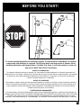
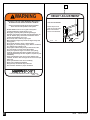
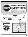
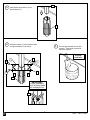
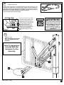
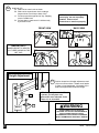
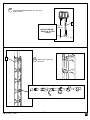
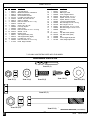
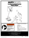
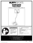
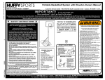
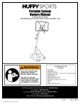
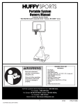
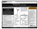
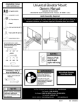
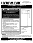
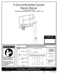
Customer Service
N53 W24700 South Corporate Circle
Sussex, WI 53089
U.S.A.
A Huffy Company
WRITE IN YOUR MODEL NUMBER:__________
In-Ground Basketball System
Owner’s Manual
SAFETY INSTRUCTIONS
FAILURE TO FOLLOW THESE SAFETY INSTRUCTIONS MAY RESULT IN
SERIOUS INJURY, PROPERTY DAMAGE AND WILL VOID WARRANTY.
Owner must ensure that all players know and follow these rules for safe
operation of the system.
To ensure safety, do not attempt to assemble this system without following the
instructions carefully. Proper and complete assembly, use and supervision is
essential for proper operation and to reduce the risk of accident or injury. A high
probability of serious injury exists if this system is not installed, maintained, and
operated properly. Check entire box and inside all packing material for parts
and/or additional instructional material. Before beginning assembly, read the
instructions and identify parts using the hardware identifier and parts list in this
document.
• If using a ladder during assembly, use extreme caution.
• Two (2) people are recommended for this operation.
• Seat the pole sections properly. Failure to do so could allow the pole sections to
separate during play.
• Before digging, contact utility company to locate underground power cables, gas,
and water lines. Ensure there are no overhead power lines within 20 ft. (7 m) radius
of pole location.
• Climate, corrosion, excessive use, or misuse could result in system failure.
• If technical assistance is required, contact Huffy Sports.
• Minimum operational height is 6' 6" (1.98 m) to the bottom of backboard.
• This equipment is intended for home recreational use only and NOT
excessive competitive play.
• Read and understand the warning label affixed to pole. Label is shown on page 6.
• The life of your basketball pole depends on many conditions. The climate,
placement of the pole, the location of the pole, exposure to corrosives such as
pesticides, herbicides or salts are all important.
• Adult supervision is recommended when adjusting height.
• Serious injury could occur if teeth/face come in contact with backboard, net, or rim.
REQUIRED TOOLS AND
MATERIALS:
• Two People
• Tape Measure
• Tape
• Shovel and Spade
• Concrete, 900 lb. (408 kg) and Container to Mix
• Carpenter’s Level
• Wood Board (Scrap)
Most injuries are caused by misuse and/or not following instructions.
Use caution when using this system.
• Step Ladder 8 ft. (2.4 m)
• Wrenches: (Two) 1/2”, 9/16”, 3/4” or two Large and
For more information on assembly, placement, proper use and maintenance, visit
The American Basketball Council website at http://www.smarthoops.com.
Small Adjustable Wrenches
• Drill
• Safety Goggles
In U.S. and Canada only: Have questions...don’t go back to the store!
We appreciate your purchasing one of our many fine products. We are sure that you will be very satisfied with your selection. Although
great care and effort have been taken, occasionally problems may occur. To ensure prompt and correct handling of any problems, or to
answer any questions, please contact our Toll-Free Customer Service Number listed below. Service will be quicker if you have your
Model Number (found on carton) and assembly instructions ready when calling. PLEASE WRITE YOUR MODEL NUMBER IN
THE SPACE PROVIDED ABOVE.
Toll-Free Customer Service Number for U.S: 1-800-558-5234, For Canada: 1-800-284-8339, For Europe: 00 800 555 85234
(Sweden: 009 555 85234),
For Australia: 1-800-333 061 - Internet Address: http://www.huffysports.com
© COPYRIGHT 2001 by HUFFY SPORTS
printed on recycled paper
1
05/03
P/N 211376A
BEFORE YOU START!
To ensure optimal playability of backboard system, a close tolerance fit between the elevator
components and hardware is required. Test fit large bolts into large holes of elevator tubes,
backboard brackets and triangle plates. Carefully rock them in a circular motion to ream out
any excess paint from holes if necessary.
AVANT DE COMMENCER !
Pour garantir l'utilisation optimale du panneau, les composants du système élévateur et la visserie doivent être bien
ajustés (serrés). À titre d'essai, insérez les gros boulons dans les gros trous des tubes du système élévateur, des supports
du panneau et des plaques triangulaires. Basculez-les avec précaution en imprimant un mouvement circulaire pour
éliminer l'excédent de peinture, si nécessaire.
¡ANTES DE COMENZAR!
Para asegurar el óptimo rendimiento del sistema del respaldo en el juego, se requiere un ajuste de tolerancia estrecha
entre los componentes del elevador y el herraje. Pruebe el ajuste de los pernos grandes en los orificios grandes de los
tubos elevadores, soportes del respaldo y placas triangulares. Cuidadosamente muévalos en círculos para eliminar
cualquier exceso de pintura, si es necesario.
VORBEREITENDE MASSNAHMEN
Um sicherzustellen, dass das Korbwandsystem optimal für den Spielbetrieb geeignet ist, müssen die Komponenten der
Verlängerungsvorrichtung und die verschiedenen Befestigungsteile fest miteinander verschraubt werden. Große Schrauben
zur Probe in die großen Löcher der Verlängerungsrohre, Korbwandklammern und Dreiecksplatte stecken und diese
vorsichtig in einer Kreisbewegung hin- und herbewegen, um eventuelle Farbrückstände aus den Bohrungen zu entfernen.
P/N 211376A
05/03
2
37
WARNING
HEIGHT ADJUSTMENT
FAILURE TO FOLLOW THESE WARNINGS MAY RESULT
IN SERIOUS INJURY AND/OR PROPERTY DAMAGE.
TO ADJUST BACKBOARD:
Owner must ensure that all players know and follow
these rules for safe operation of the system.
Position looped end of
crank onto hook as shown.
• DO NOT HANG on the rim or any part of the system
including backboard, support braces or net.
• During play, especially when performing dunk type
activities, keep player's face away from the backboard, rim
and net. Serious injury could occur if teeth/face come in
contact with backboard, rim or net.
• Do not slide, climb, shake or play on pole.
• When adjusting height, keep hands and fingers away from
moving parts.
• Do not allow children to move or adjust system.
• During play, do not wear jewelry (rings, watches, necklaces,
etc.). Objects may entangle in net.
• Keep organic material away from pole base. Grass, litter,
etc. could cause corrosion and/or deterioration.
• Check pole system for signs of corrosion (rust, pitting,
chipping) and repaint with exterior enamel paint. If rust
has penetrated through the steel anywhere, replace the pole
immediately.
• Check system before each use for proper ballast, loose
hardware, excessive wear and signs of corrosion and repair
before use.
• Check system before each use for instability.
• Never play on damaged equipment.
• Keep pole top covered with cap at all times.
• See instruction manual for proper installation.
Rotate crank handle to
Height
Indicator
raise or lower backboard.
Hook
201248
Crank
2/99
In the U.S.:1-800-558-5234 and Canada: 1-800-284-8339
201240
2/99
3
05/03
P/N 211376A
IMPORTANT! WRITE MODEL NUMBER FROM BOX ONTO PAGE 1 OF THIS OWNERS MANUAL
1.
Correctly identify each pole section and mark indicated distance from ends with tape.
5-1/2” (14 cm)
TOP
1
MIDDLE
5-1/2” (14 cm)
3
BOTTOM
2.
NOTE: Maximum distance
from edge of hole to edge of
playing surface 6” (15.2 cm).
Make sure ground is level with
playing surface, then dig pole hole.
WARNING!
CONTACT UTILITIES
BEFORE DIGGING.
6" (15.2 cm)
GROUND
SURFACE
24" (61 cm)
24" (61cm)
P/N 211376A
05/03
2
4
PLAYING
SURFACE
3.
3
Insert bottom pole section (3) into
ground sleeve (4).
4
4.
Assemble clamps (7) around bottom pole
and ground sleeve (4) as shown.
5.
Fill hole approximately 3/4 full with
concrete. Tamp down concrete to
release air pockets.
;;
;;
;;
PLAYING
SURFACE
7
7
8
5
8
5
6
6
4
IMPORTANT!
CLAMP ASSEMBLY
MUST BE POSITIONED
AS SHOWN BELOW.
7
5
05/03
P/N 211376A
6.
Insert ground sleeve (4) and pole section (3) into hole. Fill
remaining hole with concrete. Tamp down concrete to
release air pockets and build drainage hill. Center and level
ground sleeve assembly in hole. Check leveling on all sides
several times while concrete is curing. NOTE: Make sure
concrete is set up to clamp assembly as shown below.
IMPORTANT!
FRONT OF POLE MUST BE PARALLEL WITH
PLAYING SURFACE.
* PLAYING SURFACE
;;
;;;
;;;
;;;
;
;;;
;;
;;; ;;
;;;
;;;
* PLAYING
SURFACE
7.
After concrete cures, remove clamp
assembly and lift bottom pole section (3)
from ground sleeve (4) as shown.
3
FILL TO
HERE
1" (2.54 cm)
3
4
4
IMPORTANT!
WAIT MINIMUM OF 24 HOURS
BEFORE GOING ON TO NEXT STEP.
CONCRETE MUST CURE.
P/N 211376A
05/03
6
8.
IMPORTANT! Bounce pole top (1) and middle section (2)
together as shown until they no longer move toward taped
reference mark.
1
NOTE: Pole sections should have a 4-1/2" (11.4 cm)
minimum overlap.
9.
IMPORTANT! Add bottom pole section (3) to assembly.
Bounce pole sections together 3 times, rotate 90° and repeat
rotation bounce procedure. Continue this step until pole
sections are completely tight.
NOTE: Pole sections
should have a 4-1/2"
(11.4 cm) minimum
overlap.
10.
2
Drill a hole in the backside of each of the two pole
sections joint areas, 1” (2.54 cm) above bottom of
poles and install screws (10) as shown. NOTE: Drill
bit (9) provided.
WOOD SCRAP
11.
Insert pole cap (11) onto end of bottom pole (3). Mix
concrete (approximately 100 lbs. (45.4 kg)) and fill
pole 1”-2” (2.54-5.0 cm) below bottom elevator hole on
top pole section (1) as shown.
IMPORTANT!
CO
WAIT MINIMUM OF
24 HOURS BEFORE
GOING ON TO NEXT
STEP. CONCRETE
MUST CURE.
N
WARNING
TWO PERSON MINIMUM
REQUIRED FOR THIS
PROCEDURE.
NOT FOLLOWING
RECOMMENDATION MAY
RESULT IN BODILY INJURY.
1
CR
10
ETE
10
FILL LINE
2
IMPORTANT!
9
FAILURE TO FILL YOUR POLE
COMPLETELY WITH CONCRETE AS
DESCRIBED IN THESE
INSTRUCTIONS WILL VOID ALL
WARRANTIES WRITTEN OR
IMPLIED.
)
54
2.
(
1"
cm
11
3
7
05/03
P/N 211376A
WARNING
IMPORTANT!
ELEVATOR HOLES MUST BE PARALLEL WITH
PLAYING SURFACE.
TWO PERSON MINIMUM
REQUIRED FOR THIS
PROCEDURE.
NOT FOLLOWING
RECOMMENDATION MAY
RESULT IN BODILY INJURY.
12.
Remove pole cap (11) from bottom pole section and
insert clamp cover (12) onto bottom section (3). Bend
back exposed top flange sections of secured ground
sleeve (4) as shown. Then insert pole into ground
sleeve (4).
13.
Secure clamps (7) around pole section as shown. Refer
to Step 4. Tighten completely.
;;;
;;;
;; ;;;
;;;
12
PLAYING
SURFACE
3
12
7
11
4
12
14.
Lower clamp cover (12) over clamps and snap into
proper position.
P/N 211376A
05/03
8
15.
Beginning with top hole in left and right screw jack support plates (16 & 17), install elevator tubes (15) to
pole as shown. Then secure lower holes in support plates to pole.
NOTE: Not all holes in support plates (16 & 17) are used in this assembly.
1
TOP
17
16
14
16
17
14
18
13
18
19
14
14
15
F
R
O
N
T
15
IMPORTANT!
DO NOT OVER
TIGHTEN.
9
05/03
P/N 211376A
23
11
22
16.
Attach height decal (20) on screw jack (21). Align
lower edge of decal (20) with bottom of black
indicator tube.
21
1
9
8
7
20
SCREW JACK
BOTTOM
17.
Center screw jack (21) between support plates
(16 & 17) and secure as shown below.
18.
Attach logo label (22) to height indicator cover (23).
Place cover (23) over screw jack (21). Install pole
cap (11).
15
15
7'
IMPORTANT!
2.1m
DO NOT OVER
TIGHTEN.
14
14
24
24
18
18
16
17
21
POLE
P/N 211376A
05/03
10
FRONT
VIEW
19.
Secure upper elevator tubes (15) to
pole assembly as shown.
26
26
14
18
13
IMPORTANT!
14
DO NOT OVER
TIGHTEN.
½
15
15
15
14
23
15
25
13
20.
18
14
15
Insert spacer (25) through top
holes of height indicator cover (23)
and screw jack assembly as
shown. Align spacer (25) and
screw jack assembly between
elevator tubes (15) and secure.
15
IMPORTANT!
7'
2.1m
SCREW JACK
ASSEMBLY
11
WHEN SECURING SCREW
JACK (21) TO TOP
ELEVATOR TUBES (15),
USE SPACER (25)
BETWEEN ELEVATOR
TUBES AS SHOWN.
05/03
P/N 211376A
29
REAR VIEW OF
Y-FRAME (27)
29
27
21.
28
Loosely assemble bolt (28) and nut (29) to
Y-frame support bracket (27) as shown.
Repeat for opposite side. NOTE: Bolt
(28) heads face outward toward
backboard.
28
28
15
15
28
27
22.
NOTE: Two people
recommended for this
operation. Attach Y-frame
support bracket (27) to elevator
tubes (15) as shown.
7'
2.1m
30
NOTE:
Same hardware
used for upper
and lower
installation.
30
IMPORTANT!
18
05/03
DO NOT OVER
TIGHTEN.
18
14
14
18
15
14
P/N 211376A
30
14
14
12
18
15
14
30
23.
Lift backboard upright and insert bolt (28) heads into key slots. Slide backboard downward to position bolt (28)
into channel as shown. Align rim mounting holes on Y-frame support bracket (27) to rim holes on backboard
and tighten completely.
WARNING
TWO PERSON MINIMUM
REQUIRED FOR THIS
PROCEDURE.
NOT FOLLOWING
RECOMMENDATION MAY
RESULT IN BODILY INJURY.
29
28
½
27
IMPORTANT!
ALIGN RIM
MOUNTING HOLES
WITH HOLES IN YFRAME
13
05/03
P/N 211376A
24.
Install net clips (34).
The Quick Clip™ rapid release net system lets the net pull away from the rim. This
reduces the risk of player injury or property damage. However, improper installation or
a ball making contact at an odd angle may disengage the net clip from the goal rim.
Usually, the clip is reinstalled with little or no problem. We hope that you agree this
inconvenience is minor when compared to the safety of the players.
Quick Clip: US Patent No. 5,792,010/5,795,253
OUTSIDE VIEW
34
33
The two outer hooks on net clip must
face towards inside of goal rim. Insert
larger hole in net clip onto rim stud,
push down on net clip, then slide net
clip right, locking or snapping securely
into position (clips must "snap" into
place to insure a secure fit).
NOTE: Net clips should not slide
with ease. It is very important that
the net clips are in the locked
position before going on to next
step.
OUTER HOOKS
WARNING
USE OF THIS PRODUCT WITHOUT
PROPER INSTALLATION OF NET
CLIPS, OR WHEN ALL NET CLIPS
ARE NOT PRESENT COULD
RESULT IN BODILY HARM. BE
SURE TO FOLLOW DIRECTIONS
CAREFULLY.
25.
Attach rim (33).
Note: Mounting nuts (29) and
bolts (31) supplied with rim
hardware.
Refer To Instructions
Included With Rim
Hardware For Rim
Assembly.
½
29
33
31
P/N 211376A
05/03
14
26.
Install net (35).
A. Slide net into outer hook as shown.
B. Slide net into second outer hook creating a
loop as shown. Push loop to back of clip.
C. Pull loop up and through back of clip, snapping
over the middle hook.
D. Pull net down to make sure it is held securely
by all three hooks.
NOTE: If net releases during
normal play, net was improperly
installed. Please review
instructions to install net properly.
FRONT VIEW
35
IMPORTANT!
MAKE SURE NET IS HELD BY
ALL THREE HOOKS ON THE
NET CLIP.
BACK VIEW
A
C
35
33
33
B
D
Height Adjustment
27.
Position looped end of height adjustment crank
(36) onto hook as shown. Rotate crank handle
to raise or lower backboard. View label (20) to
determine approximate backboard height.
NOTE: If height adjustment is difficult
to operate, you may have over
tightened the areas indicated. Refer
to Steps 15, 19, 20, and 22.
20
WARNING
36
HOOK
STORE CRANK OUT OF REACH OF
CHILDREN. DO NOT ALLOW CHILDREN TO
ADJUST HEIGHT WITHOUT ADULT
SUPERVISION COULD RESULT IN SERIOUS
BODILY HARM AND/OR PROPERTY DAMAGE.
15
05/03
P/N 211376A
28.
Apply height adjustment label (37) to front of
pole as shown.
HUFFYSPORTS
37
10 feet
(3.05 m)
REGULATION RIM
HEIGHT IS 10 FEET
(3.05 M).
32
P/N 211376A
29.
05/03
Secure pole pad (32)
as shown.
16
PARTS LIST
Item Qty. Part No.
1
2
3
4
5
6
7
8
9
10
11
12
13
14
15
16
17
18
19
20
1
1
1
1
2
4
2
2
1
2
1
1
3
16*
4
1
1
10
1
1
900757
900874
908215
206500
201124
203232
206512
206252
202872
202871
206899
206502
201640
203474
900883
906277
906276
201646
206262
211236
Item Qty. Part No.
Description
Top Pole Section
Middle Pole Section, Flared End
Bottom Pole Section
Ground Sleeve, Square
Lock Nut, Hex Head, 3/8 x 16
Washer, Flat, 3/8 x 3/4 O.D.
Clamp, V-shaped
Bolt, Hex Head, 3/8-16 x 1 Long
Drill Bit, 3/16
Screw, Tap, 1/4 x 3/4
Pole Cap, Square
Clamp Cover
Bolt, Hex Head, 1/2-13 x 7-1/4 Long
Washer, 1/2 I.D.
Elevator Tube
Jack Support Plate, (Left)
Jack Support Plate, (Right)
Lock Nut, Hex, 1/2-13
Bolt, Hex Head, 1/2-13 x 5 Long
Decal, Height Indicator
21
22
23
24
25
26
27
28
29
30
31
32
33
34
35
36
37
1
1
1
2
1
2
1
2
6
4
1
1
1
12*
12*
1
1
1
Description
805231
202795
206234
206272
206275
201651
906266
206263
203100
206261
202662
808804
Screw Jack
NBA Logo, Label
Cover, Height Indicator
Bolt, Hex Head, 1/2-13 x 1
Spacer, 3/4 O.D. x 4-9/16
Spacer, Plastic, 1/4 Thick
Y-Frame Support Bracket
Bolt, Carriage, 5/16-18 x 3 Long
Nut, Flange, 5/16 x 18
Bolt, Hex Head, 1/2-13 x 3 Long
Bolt, Hex Flange, 5/16-18 x 4-1/2
Pole Pad
Rim
Clip, Net Holder, (Black)
Clip, Net Holder, (Red)
Net
Crank, Height Adjustment
Label, Height Adjustment
200121
200120
204282
806259
201248
* YOU MAY HAVE EXTRA PARTS WITH THIS MODEL.
HARDWARE IDENTIFIER
Item #9 (1)
Item #5 (2)
Item #6 (4)
Item #10 (2)
Item #8 (2)
Item #14 (16*)
Item #13 (3)
Item #18 (10)
Item #19 (1)
17
/
HARDWARE IDENTIFIER (CONTINUED)
05/03
P/N 211376A
HARDWARE IDENTIFIER (CONTINUED)
Item #25 (1)
Item #24 (2)
Item #28 (2)
Item #29 (6)
Item #26 (2)
Item #34 (12*)
Item #30 (4)
Item #31 (4)
* YOU MAY HAVE EXTRA PARTS WITH THIS MODEL.
P/N 211376A
05/03
18