1
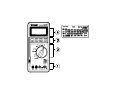
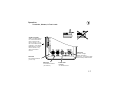
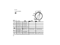
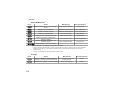
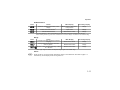
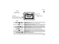
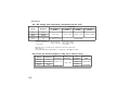
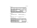
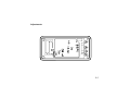
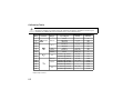
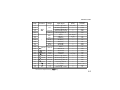
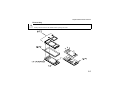
HP 974A Multimeter
User’s Guide
Part Number 00974-90002
March 1995
© Copyright Hewlett-Packard Company 1994, 1995
All Rights Reserved
HP 974A Multimeter
Table of Contents
Safety Summary . . . . . . . . . . . .
Safety Symbols . . . . . . . . . . .
Maximum Overvoltage Limitations
Probes and Test Leads . . . . . .
.
.
.
.
.
.
.
.
.
.
.
.
1-4
1-4
1-5
1-6
Operation . . . . . . . . . . . . . . . . .
Terminals, Shutter, & Test Leads .
Function Switch . . . . . . . . . . . .
Function Keys . . . . . . . . . . . . .
Function Keys/Function Switch Matrix
Display . . . . . . . . . . . . . . . . .
Audio . . . . . . . . . . . . . . . . . .
.
.
.
.
.
.
.
.
.
.
.
.
.
.
1-7
1-7
1-8
1-9
1-12
1-13
1-13
Specifications . . . . . . .
General . . . . . . . . . .
DC Voltage . . . . . . . .
AC Voltage . . . . . . .
AC + DC Voltage . . . .
DC Current, AC Current
Resistance . . . . . . . .
Continuity . . . . . . . . .
Diode . . . . . . . . . . .
Frequency (AC Coupled)
Temperature . . . . . . .
dBm . . . . . . . . . . . .
.
.
.
.
.
.
.
.
.
.
.
.
.
.
.
.
.
.
.
.
.
.
.
.
.
.
.
.
.
.
.
.
.
.
.
.
.
.
.
.
.
.
.
.
.
.
.
.
.
.
.
.
.
.
.
.
.
.
.
.
.
.
.
.
.
.
.
.
.
.
.
.
.
.
.
.
.
.
.
.
.
.
.
.
.
.
.
.
.
.
.
.
.
.
.
.
.
.
.
.
.
.
.
.
.
.
.
.
1-17
1-17
1-17
1-17
1-18
1-18
1-19
1-19
1-19
1-19
1-20
1-20
Calibration and Adjustment . . . . . . . . 1-14
Required Test Equipment . . . . . . . . 1-14
Calibration Procedure . . . . . . . . . . 1-14
Adjustments
Maintenance . . . . . . . . . . . .
Battery Replacement . . . . . .
Fuse Replacement . . . . . . .
Troubleshooting . . . . . . . . .
Cleaning . . . . . . . . . . . . .
Replaceable Parts/Accessories
Replaceable Parts/Accessories . . . . . . 6-4
Disassembly . . . . . . . . . . . . . . . . 6-5
.
.
.
.
.
.
.
.
.
.
.
.
.
.
.
.
.
.
.
.
.
.
.
.
.
.
.
.
.
.
1-15
1-15
1-15
1-16
1-16
1-16
. . . . . . . . . . . . . . . . . 6-1
Calibration Table . . . . . . . . . . . . . . . 6-2
Declaration of Conformity
1-3
Safety Summary
The CAUTIONS and WARNINGS which appear on the following pages must be followed to
ensure operator safety and to retain the operating condition of the Multimeter.
1. Do not use this product beyond its specifications or for uses not intended for this product
as identified by the product functions, ranges, and hazards as indicted below.
2. To minimize possible electric shock hazard condition, connect only two leads at any one
time to any of the multimeter terminals.
3. To prevent possible electric shock hazard condition when using the current function, do not
leave one probe connected to the circuit under test and the other probe disconnected,
exposed, and readily accessible (touchable).
Safety Symbols
Indicates the operator must refer to an explanation in this manual.
Indicates terminals at which dangerous voltages may exist.
WARNING
TO AVOID ELECTRICAL SHOCK or damage to the multimeter, do not apply more than
±1000 Vdc or 1000 Vrms between any terminal and earth ground. Use caution when working with
voltages above 60 Vdc or 42 Vpeak. Ensure test leads are in good condition.
WARNING
POSSIBLE ELECTRICAL SHOCK. Do not make measurements if the case is damaged or the
rear cover is removed. Remove all electrical inputs before removing the rear cover.
WARNING
POSSIBLE ELECTRICAL SHOCK or FIRE HAZARD. Do not expose this multimeter to rain or
moisture. Do not operate the multimeter in the presence of flammable gases or fumes.
1-4
Safety Summary
WARNING
POSSIBLE ELECTRICAL SHOCK. Calibration and performance tests are to be performed by
qualified personnel only. Do not attempt calibration or test procedures unless qualified to do so.
CAUTION
To avoid damage to the multimeter for inputs above 250 Vdc or Vac, disconnect the test leads
before changing functions. Do not exceed the maximum input limits.
Maximum Overvoltage Limitations (AC and DC Voltage Functions)
1000V
MAX indicates the maximum voltage between input terminals and earth is ± 1000 V (dc or ac rms).
Do not use the multimeter on any ACV circuit where the maximum impulse overvoltage may
be more than 4000Vpk or any DCV circuit where the maximum impulse overvoltage may be
more than 2500Vpk between the COM and VOLT terminals. Excessive impulse overvoltage
can damage the multimeter voltage functions. Do not measure branch circuits (CAT II) over
600V to earth or service panel circuits (CAT III) over 300V to earth.
1-5
Safety Summary
Function
10 A
mA or µA
Maximum Operating Input
± 10 A (dc or ac rms) / 600 V
± 500 mA (dc or ac rms) / 250 V
Resistance, Diode Test,
Temperature, Continuity
500 V (dc or ac rms)
Frequency
(10 Hz to 9.999 kHz)
(9 kHz to 200 kHz)
500 Vrms
100 Vrms
V
± 1000 Vdc or 750 Vrms
Probes and Test Leads
1. Always inspect probes before use. Do not use test leads whose insulation has cuts,
cracks, or other damage that may result in reduced electric shock protection.
2. Keep insulation surface clean between the probe tip connector and the finger guards.
3. If probes other than the ones specified are to be used with the multimeter, be sure the
probes and their leads are rated for the voltage and current to which they will be subjected.
Do not exceed the voltage ratings for the multimeter.
4. Probes supplied with this multimeter are rated for use up to 1000Vrms or Vdc.
1-6
Operation
Terminals, Shutter, & Test Leads
SAFETY SHUTTER
Slide up to open shutters
for current measurement
inputs. Must have the
function switch in one of
the Current Measurement
positions to open shutter.
Close shutter to change
function switch to any
other measurement
function.
RED LEAD
DC & AC Voltage,
Diode, Resistance,
Frequency, Temperature, dBm
and Continuity Measurements
RED LEAD
Current Measurements
(0 A to 10 A)
RED LEAD
Current Measurements
(0 to 400 mA)
BLACK LEAD
COMMON
ALL Measurements
1-7
Operation
Function Switch
Switch
Position
Display
10A
DC Current
(1 mA to 10 A)
DC Current
(10 µA to 0.5 A)
DC Current
(1 µA to 0.05 A)
DC Current
(0.01 µA to 0.5 mA)
AC Current
(1 mA to 10 A)
AC Current
(10 µA to 0.5 A)
AC Current
(1 µA to 0.05 A)
AC Current
(0.01 µA to 0.5 mA)
Diode Test
Auto Diode Test
Resistance
( 0.01 Ω to 50 MΩ)
DC Millivolts
(10 µV to 500 mV)
DC Volts
(100 µV to 1000 V)
AC Volts
(1 mV to 750 V)
Continuity
(alarm at < 100 Ω)
Temperature in °F
(-112° F to 302° F)
Temperature in °C
(-80° C to 150° C)
AC + DC Volts
(1 mV to 750 V)
Frequency
(10 Hz to 200 kHz)
Frequency and Volts 1
(10 Hz to 200 kHz)
dBm
(-59.94 dBm to 62.22 dBm)
500 mA
50 mA
500 µA
Ω
mV
V
V
1
1-8
Voltage and frequency readings alternate on display
Operation
Function Keys
Power
Automatic power off after 30 minutes. Alarm sounds 30 seconds before automatic power off.
Press any key or change any function to cancel automatic power off. Defeat automatic power
off by holding
key for 2 seconds while applying power.
Relative/Percent
Press
Action
Makes the displayed measurement
the reference
Calculates the percentage change
from the reference
Cancels the Relative/% function
Main Display
Secondary Display
Each measured value relative to
Range
the reference value (difference)
Each measured value as a
percent change of the reference
Range
value
Measurement value
Range
Perform a zero adjust when using the 500 Ω range and displayed value is less than 99 by shorting the test
leads and pressing this key. Cycle power to erase the stored zero adjustment.
1-9
Operation
Minimum/Maximum
Press
1
Action
Begin recording of min, max, and avg
values
Main Display
3
Secondary Display
Each measured value
Elapsed time
Display recorded maximum
Maximum measurement
Time of Maximum
Display recorded minimum
Minimum measurement
Time of Minimum
Display recorded average
Calculated average
Elapsed time
Display last recorded measurement
Latest measurement
Elapsed time
Pause recording of minimum and
maximum values
Resume recording of minimum and
maximum values
Last measured value
Total elapsed time
Each measured value
Elapsed time
Press and hold 1 second to cancel
-
-
1
Automatic power off is disabled when Min/Max is selected.
2
Time is recorded and displayed in minutes and seconds up to 99’ 59". After 99’ 59" time is recorded and
displayed in minutes up to the maximum recording time of 1999 minutes. Recording will stop at the
maximum time.
3
Average is computed from all readings during elapsed time.
2
Average
Press
1-10
Action
Makes the displayed measurement the
average of the last eight measurements
Main Display
Average value of last eight
measurements
Secondary Display
Disables the averaging of measurements
Each measurement
Range
Range
Operation
Hold/Auto-Hold
Press
Action
Holds the measurement value in the
display
Enters Auto-Hold function
1
Cancels Hold function
1
Main Display
Measurement value when
hold pressed
Secondary Display
Input value
Range
Measurement value
Range
Range
Auto-Hold Operation. When measurement becomes stable, multimeter will beep and save the
stable reading. Removing probe from measurement circuit will display and hold the last stable reading.
Range
Press
Action
Changes from auto-ranging to manual
ranging
Change manual range UP once with
each keypress 1
Returns to auto-ranging when key is held
for 1 second
1
Main Display
Secondary Display
Measurement value
Range
Measurement value
Range
Measurement value
Range
When upper range is reached, the sequence begins again at the lowest range.
Select
Press this key to use the functions indicated in yellow on the multimeter. See table on page 1- 8.
Hold this key to test display when turning meter on.
1-11
Operation
Function Keys and Function Switch Matrix
Function
Min/Max
3
Average
Data Hold
Auto-Hold
•
•
•
•
•
•
•
•
•
•
•
•
•
•
•
•
•
•
•
•
•
•
•
•
•1
•
•
•
V
•
•
•
•
•
•
•
•
•
•
V
•
•
•
•
µA, mA, 10A
Ω
°F, °C
mV
Hz+V
•
dBm
1-12
%
(Percent)
•
•
•
µA, mA, 10A
Hz
Relative
1
Invokes zero adjust when display is less than 99.
2
Changes input attenuator, frequency is always auto range.
3
Secondary display shows elapsed time (in seconds and minutes).
Range
•
•
•
•
•
•
•2
•
Operation
Display
Low Battery indicator
Replace batteries when on.
Main Display
(Not all annunciators shown)
Number of digits is set by range and function
Displays O.L to indicate an overload condition
Entire display flashes if input overvoltage
Secondary Display
Shows:
Range (most functions)
except for
Elapsed time (Min/Max)
Audio
Power on
First beep at power on.
Second beep when beginning to make measurements.
Single beep
Indicates any valid function key press.
Indicates a new High or Low value recorded when in Min/Max function.
Steady repeating beep
Indicates when measurement is steady when using Auto-Hold function.
Rapid repeating beeps
Indicates wrong input terminals used for function selected.
Indicates an overload condition at the measurement terminals.
Continuous tone
Indicates a resistance of < 100 Ω when using the Continuity function.
Auto Power Off
Pairs of beeps for 30 seconds.
Long beep just before power off.
Cancel by changing function switch position or pressing any key.
1-13
Calibration and Adjustment
Required Test Equipment
The source used for the calibration should have an output accuracy as good or better than
that listed in the specifications.
Calibration Procedure
Environmental range for calibration: 23° C ± 5° C, < 80% RH
Calibration interval: 6 Months
1
Disconnect all inputs from the multimeter and open the case as described on page 6-5.
2
Install new batteries (described below) and close the cover. Turn the multimeter on and allow a
30 minute warm-up. Open the case.
3
Set the multimeter function and range and the source output to the values specified at each step
in the calibration table on page 6-2.
4
When appropriate, make the adjustments indicated in the calibration table to bring the multimeter
display within the limits.
CAUTION
Dangerous voltages are present during the calibration procedure. Calibration should only be
performed by qualified service technicians Use a non-conductive adjustment tool.
1-14
Maintenance
Operator protection from electric shock hazard is provided by a double insulated enclosure.
Refer to pages 1-4 and 1-5 for maximum voltage specifications. When servicing, use only
specified replacement parts.
Battery Replacement
Replace the battery when the symbol appears in the display or before calibration. Replace
both batteries at the same time. Use high-quality type AA alkaline (IEC LR6) batteries.
Remove the batteries if the multimeter is to be stored for extended periods of time. Refer to
the disassembly drawing on page 6-5.
Fuse Replacement
Fuse locations are shown in the diagram on page 6-5. Fuses are listed in the replaceable part
list on page 6-4.
CAUTION
For continued protection use only the specified manufacturers part number or HP part number
fuse for replacement purposes.
1-15
Maintenance
Troubleshooting
Problem
Possible Cause
Suggested Action
Unit won’t turn on
Dead Batteries
Unit won’t turn off
Input limit exceeded
Remove test leads and press any key to reset.
Display flashes and Rapid
beeps
Input limit exceeded
Remove test leads and press any key to reset.
Battery Annunciator on
Low battery voltage
Replace batteries
Unable to measure current
10 A or mA - µA
Blown input protection fuse
Replace batteries
Replace fuse(s)
Cleaning
Wipe instrument with a soft rag dampened with soap and water. Do not immerse in water.
Do not use chemical cleansers or solvents.
Replaceable Parts/Accessories
Refer to the disassembly diagram on page 6-5.
1-16
Specifications
Calibration period: six months minimum. Specifications apply at 23°C ± 5°C, < 80% RH
Accuracy = ± (% of reading + number of digits)
Temperature Coefficient = Accuracy 0.1/° C (0° C to 18° C; 28° C to 55° C)
General
Do not expose product to moisture or rain. Do not use product in flammable atmosphere.
Operating Temperature: 0° to 40°C / 80% RH max (no condensation).
Storage Temperature: -25°C to 60°C / 20% to 70°C RH (no condensation).
Display reading rate: Approximately 2 — 4 times/second
Display rate for frequency measurements: Approximately 1 times/second
Battery life: Approximately 120 hours on DCV
DC Voltage
Range
500 mV
5V
50 V
500 V
1000 V
Resolution
10 µV
100 µV
1 mV
10 mV
100 mV
Accuracy
Input Resistance
> 1000 MΩ
11 MΩ (nominal)
± (0.05% + 2)
10 MΩ (nominal)
Normal Mode Rejection Ratio: (NMR) > 60 dB @ 50 or 60 Hz
Effective Common Mode Rejection Ratio (CMR) 1 kΩ imbalance: > 120 dB @ 50 or 60 Hz
AC Voltage (RMS responding, calibrated to display rms)
Range Resolution
500 mV
5V
50 V
500 V
750 V
10 µV
100 µV
1 mV
10 mV
100 V
20 Hz to
50 Hz
± (1% + 30)
50 Hz to
10 kHz
± (0.7% +30)
Accuracy
10 kHz to
30 kHz
± (2% + 50)
± (0.5% + 30)
± (1% + 40)
± (1% + 30) 20 Hz to 1 kHz
30 kHz to
50 kHz to
50 kHZ
100 kHz
Not Specified
± (2% + 70)
Not Specified
± (3% + 300)
Input
Impedance
(nominal)
11 M Ω
< 50 pF
10 M Ω
< 50 pF
1-17
Specifications
AC + DC Voltage (rms responding, computed from acV, dcV)
Range
Resolution
5V
50 V
500 V
1 mV
10 mV
100 mV
± (1% + 30)
750 V
1V
± (1% + 30)
DC, 20 Hz to 1 kHz
DC, 20 Hz to
10 kHz
Measurement range:
500 mV to 500 V ranges
20 Hz to 30 kHz
30 kHz to 100 kHz
750 V range
Accuracy
DC, 10 kHz to DC, 30 kHz to
30 kHz
50 kHZ
DC, 50 kHz to
100 kHz
± (1.2% + 40)
± (3.5% + 300)
± (2.5% + 70)
Not Specified
5% to 100% of range
10% to 100% of range
75 V to 750 V
Response time: < 2 seconds for AC, 5 seconds for AC+DC on fixed range
Crest factor: <3
Common Mode Rejection Ratio (CMR) 1 k Ω imbalance: > 60 dB @ DC to 60 Hz
DC Current, AC Current (40 Hz to 1 kHz), 5% to 100% of range
1-18
Range
Resolution
500 µA
50 mA
500 mA
10 A
10 nA
1 µA
10 µA
1 mA
DC Current
Accuracy
± (0.3% + 2)
± (0.7% + 2)
AC Current
Accuracy
± (1% + 20)
Input
Resistance
< 1050 Ω
< 12 Ω
< 2.5 Ω
< 0.05 Ω
Maximum
Input
0.5 A (fused)
15 A (fused)
Specifications
Resistance
1
Range
Resolution
500 Ω
5.0 kΩ
50 kΩ
500 kΩ
5.0 MΩ
50 MΩ
10 mΩ
100 mΩ
1Ω
10 Ω
100 Ω
1 kΩ
Accuracy
± (0.06% + 2)
1
± (0.06% + 2)
± (0.5% + 1)
± (1.0% + 2)
Test Current
Max
Open Circuit
Voltage
< 800 µA
< 5.5 V
< 80 µA
< 15 µA
< 1.5 µA
< 150 nA
< 2.2 V
After zero adjust of input leads. Zero adjust range up to 0.99 Ω.
Response time: 500 Ω to 500 kΩ — < 2 seconds, 5 MΩ to 50 MΩ — < 10 seconds.
Continuity
Measurement Current: 0.8 mA maximum
Displayed resistance: 0 Ω to 499.99 Ω
Alarm: Tone when input < 100 Ω ± 50 Ω
Open circuit voltage: < 5.5 Vpeak
Input protection: 500 Vrms (sinewave)
Resolution: 10 mΩ (<100 mSec response time)
Diode
Measurement current: +1.0 mA nominal @ 0.6 V Open circuit voltage: < 5.5 Vpeak
Displayed Voltage: 0 V to 4.999 V
Input protection: 500 Vrms (sinewave)
Accuracy: ± (1% + 2)
Resolution: 100 µV
Frequency (AC Coupled)
Frequency Range
10 Hz to 99.99 Hz
90 Hz to 999.0 Hz
900 Hz to 9.999 Hz
9.00 kHz to 99.99 kHz
90 kHz to 200 kHz
Resolution
0.01 Hz
0.1 Hz
1 Hz
10 Hz
100 Hz
Accuracy
Input Voltage (rms)
0.45 mV to 500 V
± (0.05% + 1)
.7 V to 100 V
1.5 V to 100 V
1-19
Specifications
Temperature (5 kΩ @ 25°C Thermistor probe)
Measurement Range
Resolution
Accuracy 1
1
°C
-80° to 150°
0.1°
± 0.2°
°F
-112° to 302°
0.1°
± 0.4°
Accuracy does not include 5 k Ω Thermistor error
dBm 600 Ω 1 mW reference (rms responding, computed from AC Voltage)
Accuracy
10 kHz to
30 kHz to
30 kHz
50 kHz
Input dBm
Input Voltage
20 Hz to
10 kHz
-29.82 dBm to
-23.80 dBm
-23.80 dBm to
-3.80 dBm
-3.80 dBm to
55.28 dBm
55.28 dBm to
59.72 dBm
25 mV to 50 mV
± 0.2 dBm
± 0.50 dBm
50 mV to 499.99 mV
± 0.15 dBm
± 0.30 dBm
0.5 V to 450.00 V
± 0.10 dBm
± 0.20 dBm
450 V to 750 V
± 0.15 dBm
to 1kHz
Dynamic range: -59.94 dBm to 59.72 dBm (0.8 mV to 750 V),
Accuracy not specified below -29.82 dBm (25 mV)
Display reads OL (overload) outside dynamic range
1-20
50 kHz to
100 kHz
Not specified
± 0.5 dBm
Not specified
± 1.00 dBm
Adjustments
6-1
Calibration Table
CAUTION
Dangerous voltages are present during the calibration procedure. Calibration should only be
performed by qualified service technicians using a non-conductive tool.
Step
1
2
3
4
5
6
7
8
9*
10 *
11
12
13
14
15
16
Function
500 mV
500 mV
50 V
V
5V
500 V
1000 V
V
5V
* Repeat steps 9 and 10.
6-2
Range
500 mV
500 V
5V
Short
480.0 mV
-480.0 mV
48.000 V
-48.000 V
4.800 V
480.00 V
1000 V
Adjustment
(limit)
—
1 (±2)
—
2 (±2)
—
3 (±2)
RV4 (±2)
RV5 (±1)
Tolerance
(counts)
±2
±26
±26
±26
±26
±26
±26
±7
4.8000 V @ 200 Hz
6 (±10)
±270
0.2500 V @ 200 Hz
7 (±5)
±42
480.0 mV @ 200 Hz
480.00 V @ 10 kHz
480.00 V @ 100 kHz
480.00 V @ 200 Hz
4 .8000 V @ 10 kHz
4 .8000 V @ 100 kHz
8 (±10)
C1 (±20)
—
—
C2 (±20)
—
±366
±270
±1740
±270
±270
±1740
Input Signal
Calibration Table
Step
Function
Range
Input Signal
Adjustment
(limit)
C3 (±20)
—
—
—
—
zero adjust 1
9 (±5)
—
—
—
—
—
—
—
—
Tolerance
(counts)
±270
±1740
±270
±366
±105
±1
±30
±30
±30
±30
±242
±482
±2
±146
±146
±146
50 mA
50 mA
48.000 V @ 10 kHz
48.000 V @ 100 kHz
48.000 V @ 200 Hz
480.00 mV @ 10 kHz
750.0 V @ 200 Hz
Short
480.00 Ω
4.8000 kΩ
48.000 kΩ
480.00 kΩ
4.8000 MΩ
48.000 MΩ
Short
480.00 µA
48.000 mA
32
500 mA
40 mA
480.00 mA
—
33
10 A
10 A
10.000 A
10 (±10)
±72
34
500 µA
500 µA
480.00 µA @ 200 Hz
—
±500
±500
17
18
19
20
21
22
23
24
25
26
27
28
29
30
31
50 V
V
500 mV
750 V
500 Ω
Ω
500 µA
5 kΩ
50 kΩ
500 kΩ
5 MΩ
50 MΩ
500 µA
35
50 mA
50 mA
48.000 mA @ 200 Hz
—
36
500 mA
500 mA
480.00 mA @ 200 Hz
—
±500
10 A
10 A
10.00 A @ 200 Hz
—
±120
500 Ω
5V
5V
0 Ω to 150 Ω
1.000 V
9.000 kHz @ 1 Vrms
—
Tone < 100 Ω
—
—
±102
±5
37
38
39
40
1
Hz
Perform zero adjustment using
key.
6-3
Replaceable Parts/Accessories
Refer to the disassembly diagram on page 6-5.
Call out
Description
HP Part Number
F1
Fuse, 500 mA, 250 V fast blow Littlefuse 216-500
DO NOT SUBSTITUTE
2110-0940
F2
Fuse, 15 A, 600 V fast blow Littlefuse KLK15
DO NOT SUBSTITUTE
2110-0941
MP1
Top case assembly
00974-64401
MP2
Dust/moisture seal
00971-64403
MP3
Bottom case assembly (includes stand)
00974-64402
Rubber Boot
00971-86001
Replacement Test Leads, 2 pair
E2305A
Temperature probe, 5 KΩ Thermistor
E2308A
Surface temperature sensor,
Thermistor ±0.1°C
12" lead, requires dual banana plug
40653B
Soft Case
(fits meter with rubber boot)
E2304A
Operator protection from electric shock hazard is provided by a double insulated enclosure. Refer to the Safety
Summary for maximum voltage specifications. When servicing, use only specified replacement parts.
6-4
Replaceable Parts/Accessories
Disassembly
WARNING
Always disconnect the test leads before opening the case.
6-5
DECLARATION OF CONFORMITY
according to ISO / IEC Guide 22 and EN 45014
Manufacturer’s Name:
Manufacturer’s Address:
Hewlett-Packard Company, Personal Measurements Operation
815 14th Street S.W., Loveland, Colorado 80537 U.S.A.
declares, that the products
Product Name:
Model Number:
Product Options:
Handheld Multimeter
HP 971A, HP 972A, HP 973A, HP 974A
None
conforms to the following Product Specifications:
Safety:
IEC 1010-01 (1990) Incl. Amend 1 (1992) / EN61010 (1993)
CSA C22.2 #1010.1 (1992)
UL 1244
EMC:
CISPR 11:1990 / EN55011 (1991): Group 1, Class A
IEC801-2:1991 / EN50082-1 (1992): 4 kV CD, 8 kV AD
IEC 801-3:1984 / EN50082-1 (1992): 3 V/m
IEC 801-4:1988 / EN50082-1 (1992): 0.5 kV Signal Lines
Supplemental Information: The product herewith complies with the requirements of the
Low Voltage Directive 73 / 23 / EEC and the EMC Directive 89 / 336 / EEC amended
by 93 / 68 / EEC (inclusive 93 / 68 / EEC) and carries the CE mark accordingly.
Loveland, Colorado
April 1, 1994
Jim White, QA Manager
European Contact: Your local Hewlett-Packard Sales and Service Office or Hewlett-Packard GmbH,
Department ZQ / Standards Europe, Herrenberger Straβe 130, D-71034 Böblingen (FAX: +49-7031-143143).
Warranty/Service
Limited 3 Year Warranty
What is Covered
The HP 974A Multimeter is warranted by Hewlett-Packard against defects in materials and
workmanship for three years from the date of original purchase. If you sell your unit or give it as
a gift, the warranty is automatically transferred to the new owner and remains in effect for the
original three year period. During the warranty period, we will repair, or at our option, replace at
no charge, a product that proves to be defective, provided you return the product, shipping
prepaid, to a Hewlett-Packard service center.
What is Not Covered
This warranty does not apply if the product has been damaged by accident of misuse or as the
result of service or modification by other than an authorized Hewlett-Packard service center.
No other express warranty is given. The repair or replacement of a product is your exclusive
remedy. ANY OTHER IMPLIED WARRANTY OF MERCHANTABILITY OR FITNESS IS LIMITED
TO THE THREE YEAR DURATION OF THIS WRITTEN WARRANTY. Some states, provinces, or
countries do not allow the exclusion or limitation or incidental or consequential damages, so the
above limitation or exclusion may not apply to you.
The warranty gives you specific legal rights, and you may also have other rights which vary
from state to state, province to province, or country to country.
Service
Hewlett-Packard maintains service centers in many countries throughout the world. You may
have your unit repaired at a Hewlett-Packard service center any time it needs service, whether
the unit is under warranty or not. There is a charge for repairs after the warranty period. Repair
or replacement during the first 30 days after purchase will be provided by the sales channel.
After 30 days, contact the nearest service office.
Hewlett-Packard products normally are repaired and reshipped within five (5) working days of
receipt at any service center. This is an average time and could possibly vary depending upon
the time of year and work load at the service center. The total time you are without your unit will
depend largely on the shipping time.