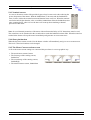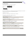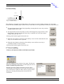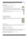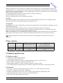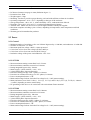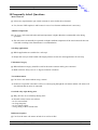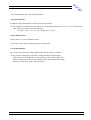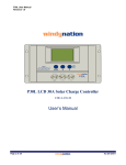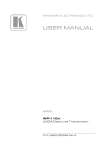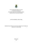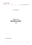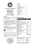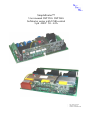
1
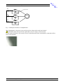
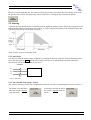
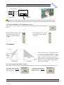
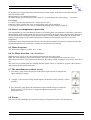
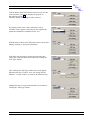
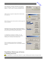
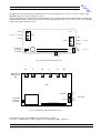
SimpleStarter™
User manual SST330i SST360i
Softstarter series with USB control
3-ph 400V 30 - 63A
-
org. date: 20-01-07
review 12-04-12
simstart- 070120ENv01
"Simple Starter” series User Manual
1 Table of contents
1 Table of contents ........................................................................................................................................................ 2
2 Introduction................................................................................................................................................................ 4
2.1 Safety guidelines .............................................................................................................................................. 4
2.2 ESD Precautions and Handling: ....................................................................................................................... 4
2.3 Standards .......................................................................................................................................................... 5
2.4 Characterization (according to EN60947-4-2) ................................................................................................. 6
3 Ordering information ................................................................................................................................................. 7
4 General description .................................................................................................................................................... 7
4.1 "SimpleStarter" general purpose digital Softstarter.......................................................................................... 7
5 Control section description......................................................................................................................................... 9
5.1 USB Diagnostics program (examples taken from the SST360i device)........................................................... 9
5.2 Starting ........................................................................................................................................................... 10
5.2.1 Auto Start.............................................................................................................................................. 10
5.2.2 The external 'Start-Stop' switch ............................................................................................................ 10
5.2.3 Start/Stop button on the diagnostics screen .......................................................................................... 11
5.3 Stopping ......................................................................................................................................................... 11
5.3.1 Disconnecting the Mains supply........................................................................................................... 11
5.3.2 The external 'Start-Stop' switch ............................................................................................................ 11
5.3.3 Start/Stop button on the diagnostics screen. ......................................................................................... 12
5.4 Current Settings.............................................................................................................................................. 12
5.4.1 Starting current (first stage) .................................................................................................................. 12
5.4.2 Starting current (second stage) ............................................................................................................. 12
5.4.3 Nominal current .................................................................................................................................... 13
5.4.4 Shear pin function................................................................................................................................. 13
5.4.5 The Motor Current readout screen........................................................................................................ 13
5.5 LED indications.............................................................................................................................................. 14
5.6 Error Relay ..................................................................................................................................................... 15
5.7 Error handling................................................................................................................................................. 15
5.8 Resetting......................................................................................................................................................... 16
6 Protective functions.................................................................................................................................................. 16
6.1 Phase sequence detection ............................................................................................................................... 16
6.2 Overcurrent..................................................................................................................................................... 16
6.3 Phase loss / low voltage detection .................................................................................................................. 16
6.4 Starter overtemperature protection ................................................................................................................. 17
6.5 Mains frequency............................................................................................................................................. 17
6.6 No Motor detection (SW 2.01 and later) ........................................................................................................ 17
6.7 The miscellaneous readout screen .................................................................................................................. 17
6.8 Presets ............................................................................................................................................................ 17
7 Installation, Maintenance & Service ........................................................................................................................ 19
7.1 Mounting instructions..................................................................................................................................... 19
7.2 Installation...................................................................................................................................................... 20
7.3 Service............................................................................................................................................................ 22
8 Fuse selection........................................................................................................................................................... 22
9 Technical specifications ........................................................................................................................................... 22
9.1 Starter control................................................................................................................................................. 22
9.2 General ........................................................................................................................................................... 22
9.3 Power.............................................................................................................................................................. 23
9.3.1 General ................................................................................................................................................. 23
Intecma reserves the right to change specifications, conditions and dimensions without further notice.
Page 2 of 22
"Simple Starter” series User Manual
9.3.2 SST330i ................................................................................................................................................ 23
9.3.3 SST360i ................................................................................................................................................ 23
10 Frequently Asked Questions .................................................................................................................................. 25
Intecma reserves the right to change specifications, conditions and dimensions without further notice.
Page 3 of 22
"Simple Starter” series User Manual
2 Introduction
2.1 Safety guidelines
•
•
•
•
•
•
Read this manual carefully before operating the equipment and follow its’ instructions.
Installation, operation and maintenance should be in strict accordance with this manual,
national codes and good practice. Installation or operating not performed in strict
accordance with these instructions will void manufacturer’s warranty.
Disconnect all power inputs before servicing the soft-starter and/or the motor.
Prior to the installation, check and verify that no parts (bolts, washers, etc) will fall into the
starter.
symbol is shown in the manual, extra care must be taken concerning mains
When this
live voltages.
Do not use insulation resistance- measuring instruments with insulation test voltages higher
than 500V when the soft starter is connected with the motor.
Attention
•
•
•
•
•
This product was designed and tested for compliance with IEC 60947-4-2.
The soft starter SST330i and SST360i are VDE certified.
Use of the product in domestic environments may cause radio interference, in which case
the user may be required to employ additional mitigation methods.
Utilization category is AC-53a or AC-53b. Form 1.
For further information see Technical Specification.
Warning
•
•
•
•
•
•
•
•
•
A series contactor or switch will be required when in case of a starter switch-off
malfunction it is necessary to switch off the load by a second switching device. This in
order to prevent danger or damage.
Internal components and P.C.B’s are at Mains potential when the soft starter is connected to
mains. This voltage is extremely dangerous and may cause death or severe injury if
contacted.
The SST330i and SST360i soft starters are an open board. The user has to care for a
corresponding cabinet and a safe installation to avoid accidental contact with the parts
which are conducting. Assembling in a closed cubicle or usage of a plastic coverage is
recommended.
When the soft starter is connected to Mains, even if start signal has not been issued, full
voltage may appear on motor’s terminals. This is also valid if the motor has been stopped or
if no control voltage is connected.
Starter must be properly grounded (except 8-22A) to ensure correct operation and safety.
Check that Power Factor capacitors are not connected to the output side of the soft starter.
Don’t interchange the mains- and the motor- connections.
Safety Guidelines require a proper circuit breaker and/ or short circuit protection in front of
the soft starter.
Grounding (PE) of the PCB is necessary. Therefore use the PE clamp on the left side
under the PCB.
2.2 ESD Precautions and Handling:
The starter itself is not particular sensitive for Electro-Static Discharge (ESD), however precautions are still
important and necessary.
The starter is produced in an ESD-safe environment.
The carton packaging box is made out of natural paper fibres without any charge collecting plastic particles or
plastic top sheet.
Intecma reserves the right to change specifications, conditions and dimensions without further notice.
Page 4 of 22
"Simple Starter” series User Manual
•
•
•
•
Before the starter is taken out of the carton, one needs to discharge his body by touching or holding a
conducting, not painted, metal part of the machine or installation were the starter must be build-in. A
grounded metal part is very much preferred.
Open now the starter's carton and take out the device by its aluminium heatsink block.
Do not touch the sensitive vertical control board. The horizontal power board may be touched.
Mount the starter into the machine or installation and hook up the wires.
2.3 Standards
SST330i VDE approved:
CB /VDE Test Certificate: DE1-41677
Date of issue: 22-12-2009
(Valid for hardware version HW5.0 and later versions)
According to:
EN60335-2-40: Household appliances, part heat pumps, air conditioners and similar equipment.
Safety and EMC Emission and Immunity (CE)
Complies with:
EN60335-1:2002 + A1:2004 + A11:2004 + A12:2006 + corrigendum:2006; A2:2006 + A13:2008
EN60335-2-40:2003 + A11:2004 + A12:2005 + A1:2006 + corrigendum:2006
Restriction of Hazardous substances in Electrical and Electronic Equipment according to Directive
RoHS 2002/95/EC.
Intecma reserves the right to change specifications, conditions and dimensions without further notice.
Page 5 of 22
"Simple Starter” series User Manual
2.4 Characterization (ac cording to EN60947-4-2)
General: Form 2 with bypass
Number of Poles: 3 phases regulated
Kind of current: AC
Rated impulse withstand voltage: Uimp 2.5kV (test voltage shape 1.2/50)
Thermal current: SST330i: Ith 30A, SST360i: Ith 63A.
Rated current: 30A (11kW) for SST330i / 63A (30kW) for SST360i
Rated uninterrupted current: 30A (11kW) for SST330i / 63A (30kW) for SST360i
Rated Frequency: 50Hz
Normal overload: class 10, x=40/Ie, T=3
Interrupting medium: SCPD (no part of the softstarter device)
Method of operation: Anti-parallel thyristors
Method of control: Semi-automatic
Method of connection: Motor in delta or star, Thyristors in series with mains supply
Rated operational voltage: Ue 400Vac
Rated Insulation voltage: Ui 500Vac
Operating capability: 400/25/100%/AC53a / AC58a
Starting/Stopping: Off / starting / fully ON / Off
Thyristor I²t: 720(A²s) for SST330i / 16200 for SST360i
Utilisation category: AC53a / AC58a
Control circuits: none / start-stop, isolated, potential-free switching contact: 0- /+5Vdc, referred to PE,
Protective Ground level
Auxiliary circuits: None
Coordination with SCPD (Short Circuit Protection Device): class B 32A for SST330i / 63A for SST360i, ie
rating dependable
Safety and installation: User. Device: Label SST330i
1)
2)
3)
4)
5)
6)
7)
8)
9)
10)
11)
12)
13)
14)
15)
16)
17)
18)
19)
20)
Manufactured in EC
Type: "SimpleStarter" SST330i, 3~ 400Vac, bypassed
Softstarter
Standard applied: EN 60947-4-2:1999+A1:2000
Ue:400Vac (+10%, -15%)
Ie: 30A: AC53a / AC58a: 1.2-3:100-12
Rated frequency: 50Hz
Duty rate: continuous operation
Form designation: Form 2
Rated insulation voltage: 500Vac
Rated impulse withstand voltage: 2500Vpk (1.2/50μs)
Pollution degree: 3 (industrial applications)
IP code: Open Frame IP00
Short circuit current: 230Amps / 20ms, 32A type-C SCPD
Switching overvoltage: not applicable
Rated control voltage: not applicable
Rating auxiliary circuits: not applicable
Characteristics overload relay: not applicable
Emission: class A, class B, if starting time =600ms max
Immunity: no specific measures required
RoHS conform
Device: Label SST360i
1)
2)
3)
4)
5)
6)
7)
8)
9)
10)
11)
12)
13)
14)
15)
16)
17)
18)
19)
20)
Manufactured in EC
Type: "SimpleStarter" SST360i, 3~ 400Vac, bypassed
Softstarter
Standard applied: EN 60947-4-2:1999+A1:2000
Ue:400Vac (+10%, -15%)
Ie: 63A: AC53a / AC58a: 1.2-3:100-12
Rated frequency: 50Hz
Duty rate: continuous operation
Form designation: Form 2
Rated insulation voltage: 500Vac
Rated impulse withstand voltage: 2500Vpk (1.2/50μs)
Pollution degree: 3 (industrial applications)
IP code: Open Frame IP00
Short circuit current: 1620Amps / 20ms, 63A type-C
SCPD
Switching overvoltage: not applicable
Rated control voltage: not applicable
Rating auxiliary circuits: not applicable
Characteristics overload relay: not applicable
Emission: class B, if starting time =600ms max
Immunity: no specific measures required
RoHS conform
Note: This product has been designed for Class A equipment; use of this product in domestic environments may cause radio
interference if starting time exceeds 600ms in which case the user may be required to employ additional mitigation measures.
Intecma reserves the right to change specifications, conditions and dimensions without further notice.
Page 6 of 22
"Simple Starter” series User Manual
3 Ordering informat ion
SimpleStarter:
Type
SST
xxx
(1)
330i
360i
3 Phase 400 V [-15%, +10%] Istart max. 47A
3 Phase 400 V [-15%, +10%] Istart max. 180A
The "SimpleStarter" softstarters are supplied without short-circuit Protective Devices, e.g. fuses, MCB or a
Thermal Electro-Dynamic Overload Relay for the 1- and 3-phase Mains.
4 General descriptio n
4.1 "SimpleStarter" gen eral purpose digital Softstarter
The "SimpleStarter" softstarter is designed as a device for simple and low cost soft starting of 3-phase 400V~
induction motors, with a low or moderate starting torque:
• Heat pumps & Chillers
• Pumps
• Fans
• Conveyors (light, moderate)
• Refrigerant Compressors
• Mixers
• Production machines
• Transformers (3-ph)
• Beverage installations
The "SimpleStarter" controls the motor voltage in all the three phases from. The device is equipped with three
build-in bypass relays. The "SimpleStarter" is developed with the aim to replace the star/delta (Y/D) switches in
applications where a galvanic separation is of lesser importance or already realised.
All "SimpleStarter" softstarters comply with all directives concerning emission, immunity and safety. The unit
is of an open frame type (IP00), therefore the user has to take care for a proper housing in. When the mains
voltage is applied or when the starter receives a starting signal, the power semi-conductors are switched-on in
such a way that it starts with a small controllable increasing current, flowing into the motor. When the motor is
at speed, the bypass relays are switched on the power semiconductors are switched off thus minimising
EMC/RFI pollution.
For the operation of the softstarter, a neutral line is not necessary.
Intecma reserves the right to change specifications, conditions and dimensions without further notice.
Page 7 of 22
"Simple Starter” series User Manual
L1
Bypass Relay
L2
M
L3
Fig. 3.1 Principal schematics of "SimpleStarter".
The "SimpleStarter" electronics is powered by the line voltage and is partly not isolated.
Both PCB boards of the device have parts that are at live voltage, so do not touch!
(see the Safety Guidelines). The control circuit is isolated from the mains and should be connected to PE to
ensure safe operation:
Intecma reserves the right to change specifications, conditions and dimensions without further notice.
Page 8 of 22
"Simple Starter” series User Manual
5 Control section de scription
5.1 USB Diagnostics pro gram (examples taken from the SST360i device)
Manipulating of the Starters parameters is done with the 'Diagnostics program'. This program
‘SimpleStarterDiag.exe’ comes together with ‘SSTsettings.ima’ and ‘mcHID.dll’. The three of them should
always be kept together in a single random chosen Windows map.
Run the Diagnostics program ‘SimpleStarterDiag.exe’ and connect the PC with a proper USB cable (Type A to
Mini B) to the SimpleStarter. Then apply the 3-phase mains voltage to the SimpleStarter.
Once the connection has been established the upper status bar shows some general information like Connection
status, Company Name (OEM situations), Starter Type, Software Version and the motor status which can be:
Motor Stopped; Motor Starting; Motor at speed; Motor Stopping.
To switch the control to the Diagnostics program click on the 'Starter' button. It will now show 'PC', all the
controls on the screen become active. The settings that are made on the screen will be taken over by the Starter.
Intecma reserves the right to change specifications, conditions and dimensions without further notice.
Page 9 of 22
"Simple Starter” series User Manual
However, keep in mind that once the control has been given back to the Starter these new settings are lost and
the previous ones will be used unless they where saved first by clicking the 'Save Parameters' button.
5.2 Starting
A general rule says the shorter the acceleration time the higher the starting current, the less the backup fuses are
heated and the higher the mechanical stress will be. A longer starting time minimises the mechanical stress but
will increase the energy loss in motor and starter.
There are three ways of starting the motor:
5.2.1 Auto Start
Use this way when the mains voltage is applied by switching an upstream contactor (external Start/Stop mode
set to Start On Open see 5.2.2 ). For the SST360i type allways use a controlled line separator/contactor to
switch-off in case the SST360i fails to switch-off.
Contactor
L1
Starter
L2
L3
Fig.5.1 Auto Start
5.2.2 The external 'Start-Stop ' switch
The external 'Start-Stop' switch can configured from firmware version 1.04 with diagnostics screen version 1.3.
The Starter will ramp down
when the switch is opened
(Stop On Open).
The Starter will ramp up when
the switch is opened (Start On
Open).
Intecma reserves the right to change specifications, conditions and dimensions without further notice.
Page 10 of 22
"Simple Starter” series User Manual
MCB / Overload
L1
SimpleStarter
L2
1 2 3
L3
K1
Controlled Start
Start-Stop
Switch
The start-stop control voltage should be operated with a potential free contact. For the SST360i type
allways use a controlled line separator/contactor to switch-off in case the SST360i fails to switch-off.
5.2.3 Start/Stop button on the diagnostics screen
The motor can also be started by clicking the Start/Stop toggle button on the diagnostics
screen.
With the Starting Voltage slider
the initial voltage can be set
from 20% to 55% of the line
voltage.
The start ramp can be set in 4
steps from 0 – 100% with the
Acc slider.
5.3 Stopping
There are three ways of stopping the motor:
5.3.1 Disconnecting the Mains supply
When a connected normally closed 'StartStop' switch is closed the Starter will ramp
down the voltage by decreasing the phase
angle of the thyristors.
5.3.2 The external 'Start-Stop ' switch
The external 'Start-Stop' switch can configured from firmware version 1.04 with diagnostics screen version 1.3.
The Starter will ramp down
when the switch is opened
(Stop On Open).
The Starter will ramp up
when the switch is opened
(Start On Open)
Intecma reserves the right to change specifications, conditions and dimensions without further notice.
Page 11 of 22
"Simple Starter” series User Manual
MCB / Overload Relay
L1
SimpleStarter
L2
1 2 3
L3
K1
Start-Stop Switch
Controlled Start
5.3.3 Start/Stop button on the diagnostics screen.
The motor can also be started by clicking the Start/Stop toggle button on the diagnostics
screen.
.
When using the external Start/Stop input or the Start/Stop button on the diagnostics program the
deceleration time can be set with the 'Dec' slider between 0 - 100 seconds.
5.4 Current Settings
5.4.1 Starting current (first st age)
After giving the starting command the current increases till is reaches the first of a two
stage current limit. The value of this limit is done with the ImMaxLow (5-47Arms) slider
as where as the maximum duration of the current is done with ImMaxLow time (1-10sec)
slider. The time that the current is stalled as the limit has been reached is counting down on
the second textbox under the slider (this time will never count up during the starting
process).
5.4.2 Starting current (second stage)
When the first stage of the current limit has elapsed and the motor is not yet at full speed
the second stage becomes active. This one is set with the ImMaxHigh (5-47Arms) slider as
where as the maximum duration of the current is done with ImMaxHigh time (1-10sec)
slider. The time that the current is stalled as the limit has been reached is counting down on
the second textbox under the slider (this time will never count up during the starting
process).
Note: when the level of the second stage is less then the first one the current will not drop but remain the level
of the first stage. This is because the Starter will not ramp down during the starting period.
After the second time has elapsed and the motor is still not yet at full speed the Starter will now stop the motor
immediately and generates an overcurrent error.
Intecma reserves the right to change specifications, conditions and dimensions without further notice.
Page 12 of 22
"Simple Starter” series User Manual
5.4.3 Nominal current
As soon as the motor reaches full speed the bypass relays become active thus reducing the
power dissipation of the Starter. With the ImMaxNom (5-30Arms) and the ImMaxNom
time (5-10sec) sliders the nominal current and duration time can be set. When the nominal
current becomes higher then the value set with the ImMaxNom slider the ImMaxNom time
starts counting down, when it is less the timer will count up thus emulating a thermal
protection of the motor.
Note: for a real thermal protection of the motor a Motor Protection Relay or PTC thermistors must be used.
The actual time can be monitored in the second textbox under the ImMaxNom time slider. When this time has
reached 0 the Starter will stop the motor immediately and generates an overcurrent error.
5.4.4 Shear pin function
When the thyristor current exceeds 55A the Starter switches off immediately and gives an overcurrent error.
This level is fixed and can thus not be changed.
5.4.5 The Motor Current read out screen
As far as the motor current settings are concerned this part shows in a more graphical way:
• The actual motor current, Imotor
• The first stage of the starting current,
ImMaxLow
• The second stage of the starting current,
ImMaxHigh
• The nominal motor current, ImMaxNom
Intecma reserves the right to change specifications, conditions and dimensions without further notice.
Page 13 of 22
"Simple Starter” series User Manual
5.5 LED indications
The unit is equipped with 3 LED's, placed on the vertical PCB.
PWR
ERROR
RUN
PCB2
Control PCB
Fig. 5.4 LED Indication
Error detection and indication is active in standby mode (motor stopped) and in running mode as well. On the
diagnostics program the indicated error will be displayed in the status bar.
Green LED on → Power-on.
Yellow LED on → Motor at speed, on board bypass relays are switched on.
Red LED flashes 2 times periodically → Phase sequence fault.
Red LED flashes 3 times periodically → Overcurrent during start and running.
Red LED flashes 4 times periodically → Heatsink overtemperature
Red LED flashes 5 times periodically → Under voltage / phase loss /low voltage starter supply.
Red LED flashes 7 times periodically → Motor not connected or bad connection
Intecma reserves the right to change specifications, conditions and dimensions without further notice.
Page 14 of 22
"Simple Starter” series User Manual
5.6 Error Relay
PCB 1
Error Relay
PCB 2
NO
NC
COM
Fig. 5.5 ERROR Relay
The softstarter is equipped with an Error Relay. The contacts are named: COM (Common), NC (Normally
Closed) and NO (Normally Open). When an error occurs there are two possibilities in the Error relay behaviour
1. The upper button shows 'Error Relay Signalling' meaning that the error relay switches
together with the Error LED.
2. The upper button on the 'Error Relay Action' of the Diagnostics program shows 'Error
Relay Steady' which means that the error relay is switched over once from contact
COM to NO. (See Fig. 5.5).
Clicking on the button toggles between the two.
1. When the lower button on the shows 'Error Relay Active On' this means that the error
relay is in rest when no error is present.
2. When the lower button on the shows 'Error Relay Active Off' the error relay is
switched on when no error is present.
Clicking on the button toggles between the two.
5.7 Error handling
Visible on SST360i from SW5.00 SST360i from SW4.00
The error handling screen consists of two parts. The left part
shows the eight most recent errors, one the right part one can
enable or disable the possible errors.
With the Clear Error History button the error list can be
cleared. Make sure that there are no recent errors before you
try to clear the list. In that case there will be a pop-up screen
that gives a message that the present error needs to be
cleared first.
Intecma reserves the right to change specifications, conditions and dimensions without further notice.
Page 15 of 22
"Simple Starter” series User Manual
After enable or disable errors it’s important to save them.
5.8 Resetting
After an error the SimpleStarter can be reset in three several ways:
1. By removing and re-applying the mains supply.
2. By clicking on the 'Reset Starter Errors' button
3. Automatically, after the Auto Reset time (1-60 min) has elapsed. Above 60 minutes
the Auto Reset is disabled (indication: Off). Only resetting as described by point 1 and
2 then will apply. The Auto Reset time will only be active when the control has been
After an error the SimpleStarter can be reset in three several ways:given to the
SimpleStarter.
In that case the actual auto reset countdown can been followed in the lower textbox in the
'SettingsMisc' part of the Diagnostics screen.
6 Protective functio ns
6.1 Phase sequence detec tion
The "SimpleStarter" has a monitoring circuit for the phase sequence of the applied mains
voltage. With the diagnostics program it is possible to toggle between left and right or
both directions.
6.2 Overcurrent
During a start the motor current is measured and the level is kept equal to the adjusted maximum current level,
with an average accuracy of about 3%. The current detection is active during motorstart and continuous
operation as well (motor overload error).
6.3 Phase loss / low volta ge detection
Phase loss:
Missing phase L1 or L3 before or during a motor start:
The starter losses one of these feeding phases, causing the internal power supply falls down. The starter does not
function anymore, normally no fault is displayed, and accidentally an overcurrent can be displayed.
A fault is indicated by the flashing the Red LED, the motor cannot be started or will be stopped.
Missing phase L2 before or during a motor start:
The starter losses phase L2, resulting in an undervoltage error message after.
Missing phase L1 or L3 at continuous operation:
Intecma reserves the right to change specifications, conditions and dimensions without further notice.
Page 16 of 22
"Simple Starter” series User Manual
the internal power supply shuts down when the motor is fully loaded. If the motor is not full loaded the
detection will not work.
Missing phase L2 at continuous operation:
the starter remains powered and will after a delay of 3 seconds display the "undervoltage" + "no motor".
Low voltage:
For correct operation the minimum line voltage must be 330V~.
If the line voltage is below this value, an undervoltage error will be displayed.
To proceed, the starter has to be reset by switching the feeding mains voltage off and on.
6.4 Starter overtemperat ure protection
The SimpleStarter power semiconductor module is protected against overtemperature. Most heat is generated
during starting. In the running mode the only heat is generated by the bypass relays and the wiring. Because of
this one should keep in mind the amount of motor starts is not only limited by the height and duration of the
starting current but also by the ambient temperature and how fast the heatsink can loose its excessive
temperature.
Temperature sensor lead interruption (software version SW2.02 and later) and sensor lead short-circuit to the
grounded heatsink will be sensed also, resulting in a temperature error message.
6.5 Mains frequency
The rated mains frequency is 50Hz -15%, +10Hz .
6.6 No Motor detection ( SW 2.01 and later)
When the motor wire U or W is not connected to the motor, this is not sensed.
Note: The motor might get started with 2 phases! The motor overload protection can become active.
When the motor wire V is not connected to the motor, this will be sensed, resulting in a "no motor" error after 3
sec.
The motor can be started again after resetting the fault (mains off-on, or with the PC program "Reset Errors")
and restoring the lost motor connection.
6.7 The miscellaneous re adout screen
1. The ‘Ramp’ gauge shows the progress of the phase angle between 0 (stopped) and
100% (maximum voltage).
2. ‘Usupply’ is the on-board voltage which supplies all internal circuitry (merely a control
function).
3. The ‘Heatsink’ gauge shows the temperature of the heatsink in degrees centigrade.
When it reaches 75°C the motor is stopped and the Starter generates an overtemperature error.’
6.8 Presets
The user can and manipulates store preferred settings of all parameter under a self named preset.
Intecma reserves the right to change specifications, conditions and dimensions without further notice.
Page 17 of 22
"Simple Starter” series User Manual
First the Starter must be hooked-up and powered. Also the
control must be given to the diagnostics program as
described in section 5.1.
Then this default screen appears fully activated.
By clicking on the arrow of the combo box a list of
available, if any, appears. Choosing one also updates the
parameters (ImMaxlow, ImMaxlow time, etc.).
With the name in the box the following actions can be done:
Editing, Deleting or Saving the parameters.
First make sure the proper type has been chosen in the
combo box. Than the name can be edited by clicking the
‘Edit Type’ button.
After clicking the ‘Edit Type’ button this screen appears.
Edit the name here. Click on ‘Save’ for storing into the
database’, or click ‘Cancel’ to return to the default screen.
Adding the name of a type in the database can be done by
clicking the ‘Add Type’ button.
Intecma reserves the right to change specifications, conditions and dimensions without further notice.
Page 18 of 22
"Simple Starter” series User Manual
After clicking the ‘Add Type’ button this screen appears.
Enter new name here. Click on ‘Save’ for storing into the
database’, or click ‘Cancel’ to return to the default screen.
Make sure the new type has a unique name. Double entries
are not allowed.
When clicking on arrow of the combo box the new type will
show up in the list.
Deleting the name of a type that is already in the database
can be done by clicking the ‘Delete Type’ button. Verify that
the correct type has been chosen in the combo box.
A confirmation screen appears. Clicking ‘Yes’ will
permanently delete the chosen name from the database.
Clicking ‘Yes’ will return to the default screen.
The ‘Save Settings’ button will store all adjustable
parameters into the database (Note: not the Starters internal;
memory).
7 Installation, Maint enance & Service
7.1 Mounting instruction s
The "SimpleStarter" is an open frame OEM device, proper shielding against touching is strongly advised.
Intecma reserves the right to change specifications, conditions and dimensions without further notice.
Page 19 of 22
"Simple Starter” series User Manual
The "SimpleStarter" is equipped with 4 nylon Snap-in locking PCB supports for easy and fast mounting.
When build in a housing, special care must be taken for sufficient free space for cooling airflow to circulate.
A full metal cabinet with cable glands for mains and motor wires is recommended.
The size of the cabinet is to be chosen with regard to motor current rating, ambient temperature and number of
starts per hour and the efficiency of the cabinet in transporting the generated heat to the ambient., ventilation
slots must be implemented for sufficient air flow.
Be sure that the cabinet air temperature does not exceed 55°C, when this can happen forced cooling should be
applied. Recommended general-purpose minimum cabinet size: LxWxH = 250x110x100 mm.
Free space around the starter should be 2.5cm.
For the wiring 105°C high performance equipment wire with sufficient current rating should be used.
In the cabinet; only starter wiring wires are allowed.
191.6mm
Fig. 7.1.1 "SST330i"
mounting holes
85.0mm
4x
dia 4.75mm ±0.08
255mm
Isolation Foil 210x115mm
PCB 203x106.6mm
117.5mm
117.5mm
10.0mm
5.0mm
PCB
153.5mm
5x
4.0mm
PCB
245.0mm
163.5mm
143.5mm
Isolation foil
255x 163.5mm
5.0mm
10.0mm
5.0mm
5.0mm
5.0mm
10.0mm
235.0m
Fig. 7.1.2 "SST360i" mounting holes
5.0mm
5.0mm
10.0mm
7.2 Installation
The Mains input is located on the PWR. PCB, at the left side there is 3-pole screw terminal block for wires up to
4mm², numbered L1/(1), L2/(3) and L3/(5). The motor terminal block (equal to the mains terminal block) is at
Intecma reserves the right to change specifications, conditions and dimensions without further notice.
Page 20 of 22
"Simple Starter” series User Manual
the right side of the Power PCB, numbered U/T1(2), V/T2(4) and W/T3(6). Use 2.5- 4.0 mm² - 500V~ type
stranded copper wire, temp. rating: 85°-105°C.
The PE ground must be connected to the terminal tab J3 (in front left) Faston Tab 4.8x0.8mm. Be sure that the
Faston crimp terminal is connected to the wire with the appropriate tooling. Use 2.5 mm² - 250V~ type stranded
copper wire, temp. rating: min. 85°C.
PCB 1
L1-R (1)
wire 4mm²
L2-S (3)
Mains
U/T1(2)
L3-T (5)
Motor
V/T2(4)
wire 4mm²
W/T3(6)
Ground /PE
Faston Tab
6,3x0.8mm
NO
NC
COM
Error
PCB2 Control Circuit
wire 1mm²
In 0V
Start-Stop
Fig. 7.2 SimpleStarter SST330i Wiring
L1
U
L2
V
L3
W
Ringtongue M6
Hex head screw
M6
PCB1
Start-Stop
0V
IN
Wire 1mm²
Ground /PE
Faston Tab
6,3x0.8mm
Error
NO
NC
COM
PCB2 Control Board
Fig. 7.3 SimpleStarter SST360i Wiring Top view
The rated wire gauge of the ERROR relay terminals is 1.0mm².
Use 250V~, stranded 0.75-1.0mm², copper wires, temperature rating: min. 85°C.
Intecma reserves the right to change specifications, conditions and dimensions without further notice.
Page 21 of 22
"Simple Starter” series User Manual
When the softstarter is to be build-in into a cabinet, take care that all wires are leaded straight to and from its
terminal blocks, not too long and not too short. When necessary tighten the wires with wire clips to the cabinet
bottom or sides, to prevent that the wires contact internal parts of the device. Tighten the screws of the terminal
blocks with a min. torque of 0.5Nm.
Any mounting position is allowed as long as sufficient cooling is guaranteed.
Do not mount the starter near heat sources.
Protect the starter against corrosive atmospheres and dust.
Warning:
Incorrect starter application or operation may cause overload and damage the power semi-conductor module
before the heatsink over-temperature protection will trip the device!
7.3 Service
Retighten the screws of the terminal blocks after the some running hours of the machine or installation, use min.
0.5Nm tightening torque.
When proper installed, the softstarter needs no servicing or maintenance during its working life.
The on-board power supply transformer primary winding has 1 protection fuse: 0.5-1AT-ceramic type, 400500V, size 6,3x32mm. A service engineer has to replace the fuse.
When servicing the device be sure that the mains supply is switched off and disconnect the wires of the mains
input terminal. Then replace the fuse. Reconnect the mains input terminal wires and switch on the power.
Installing and Operation of this product not executed in correspondence with this manual voids any
guarantee.
8 Fuse selection
Starter Type
Istart max.
MCB B-char. VDE 0641
Breaking capacity 10KA
SST330i
47A
32A
fuse class gL/gG
gL acc. VDE 0636/21
gG acc. IEC 60269-1,2-1
32A
SST360i
180A
63A
63A
9 Technical specifica tions
9.1 Starter control
•
•
•
•
•
•
Starting time: motor current controlled.
Control inputs: Manual Start-Stop.
Control outputs: Error relay, 250V-5A, SPDT, Wiring: flexible wire 250Vac, 1mm².
Min. circuit recovering time switching mains off-on: 0.3s.
Mains Supply frequency: 42-70 Hz, maximum frequency variation: 20 Hz/s.
Overcurrent protection: during starting and continuous operation (semi motor overload relay function).
9.2 General
•
•
•
•
•
Error relay: single pole; dual transition rated for 250Vac - 5A; contact material: silver alloy.
Designed to comply with VDE and UL standards.
Printed Circuit Board for power part, add-on PCB for control functions. Board quality: FR-4.
Dimensions PCB: 203 x 106.6 x 45 mm, 4 corner mounting holes.
PCB solder side shielded with polyester sheet.
Intecma reserves the right to change specifications, conditions and dimensions without further notice.
Page 22 of 22
"Simple Starter” series User Manual
•
•
•
•
•
•
•
•
•
PCB trace clearance/creepage: 4.4mm (Pollution degree: 3).
Protection class: IP00.
Weight: approx. 610gr.
Mounting: user has to provide a proper housing, safe and with sufficient coolant air circulation.
Operating temperature: -20 to +70° C: depending on the type of the enclosure.
Storage temperature: -40 to +85° C, relative humidity <90 %, condensation not allowed.
Humidity: 98% at 20°C, 85% at 55°C, occasional condensation may happen.
Altitude: max. 1000m. for devices to be used at higher altitudes consult your supplier.
Maximum complete switching cycles: 12/hour, depending on temperature, motor temperature and load
conditions.
• Warranty period 24 months after purchase.
9.3 Power
9.3.1 General
•
•
•
•
•
•
Minimum number of switching cycles over lifetime: Bypassrelay >1.000.000, semiconductors.>10.000.000.
Number of starts max.: 12 / hour.
Maximum peak line voltage: 1000V, varistor protected.
Critical rate of rise of on state voltage (dV/dt):1000V/µs.
Critical rate of rise of on-state current (dI/dt): 50A/µs.
Insulation voltage of the power semiconductors: 3kV~/1sec.
9.3.2 SST330i
•
•
•
•
•
•
•
•
•
•
Motor maximum starting current limit level: 47Arms.
Motor maximum continuous current level: 30Arms.
Rating integrated bypass relay: 30Arms.
Mains supply: 3 phase, 400Vac, +10%, -15%.
3 phase mains phase sequence detection.
Powerloss during start typ. 96W /3 phases, Ie 30Arms.
Powerloss in continuous mode typ. 26.5W / phases, Ie 30Arms.
Power consumption Starter: 3.6W.
Mains undervoltage lockout: Switch-off at voltage level < 330V(motor running).
Mains and motor screw block L1-R-(1), L2-S-(3), L3-T-(5) and T1-R-(2), T2-V-(4), T3-W-(6): 4.0mm2
/11AWG, depending on motor current rating.
• PE grounding of the device to be carried out with a 4.8x0.8mm Faston terminal.
9.3.3 SST360i
•
•
•
•
•
•
•
•
•
Motor maximum starting current limit level: 180Arms.
Motor maximum continuous current level: 63Arms.
Rating integrated bypass relay: 100Arms.
Mains supply: 3 phase, 400Vac, +10%, -15%.
3 phase mains phase sequence detection.
Powerloss during start typ. 604W /3 phases, Ie 180Arms.
Powerloss in continuous mode typ. 19W / phases, Ie 63Arms.
Power consumption Starter: 1.3W.
Mains undervoltage lockout: Switch-off at voltage level < 330V(motor running).
Intecma reserves the right to change specifications, conditions and dimensions without further notice.
Page 23 of 22
"Simple Starter” series User Manual
• Mains and motor screw block L1-R-(1), L2-S-(3), L3-T-(5) and T1-R-(2), T2-V-(4), T3-W-(6): 10mm2
/7AWG, depending on motor current rating.
• PE grounding of the device to be carried out with a 4.8x0.8mm Faston terminal.
Intecma reserves the right to change specifications, conditions and dimensions without further notice.
Page 24 of 22
"Simple Starter” series User Manual
10 Frequently Asked Questions
Main Contactor
Q: Is there any requirement to put a main contactor in series before the soft starter?
A: Yes, because VDE requires it and because in case of a soft starter malfunction it is necessary.
Ambient temperature
Q: Can I use a soft starter when the ambient temperature is higher than the recommended value during
operation?
A: The soft starter can normally be operated at a higher ambient temperature if the rated current for the unit
is derated according to the manufacturer’s recommendation
Soft Stop applications
Q: Which applications are suitable for a soft stop?
A: Pumps and conveyor belts loaded with fragile products are the two main applications for soft stop.
Utilisation Category
Q: What utilisation category should be used for the main contactor and by-pass contactor?
A: Main contactor: always use AC-3. Bypass contactor is build in.
Test without motor
Q: Can I test a soft starter without using a motor?
A: No that is not possible since there will be no current going through the soft starter and the soft starter will
also indicate that no motor is connected.
Overload relay trips during start
Q: Why do I have an overload trip during start?
A: Possible reasons can be one of these:
- too low current limit
- too long ramp time
- too low initial voltage
- wrong setting of the overload times
Different frequency
Q: Can I use the same soft starters at both 50 as well as 60 Hz?
Intecma reserves the right to change specifications, conditions and dimensions without further notice.
Page 25 of 22
"Simple Starter” series User Manual
A: No at the moment only with 50 Hz sinusoidal.
Voltage fluctuations
Q: Which voltage fluctuations are allowed for the soft starters?
A: The minimum- and maximum value where we can guarantee full function is -15 % to +10 % of the rated
value. This is also stated in the IEC-standard.
Example: 400 V - 15 % to +10 %. Range 340 V - 440 V.
Semi-conductor fuses
Q: Do I have to use semi-conductor fuses?
A: No, fuses with a type C characteristic are recommended.
Use in high altitudes
Q: Can I use the soft starter at high altitudes and what do I have to consider?
A: It is possible. When using soft starters at high altitudes the rated current
for the unit has to be derated due to less cooling. In some cases a larger soft
starter is required to be able to cope with the motor current when used at high
altitudes. For questions, please consult factory!
Intecma reserves the right to change specifications, conditions and dimensions without further notice.
Page 26 of 22