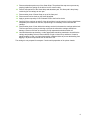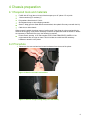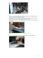
1
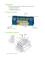
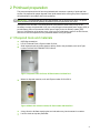
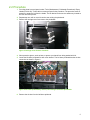
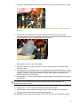
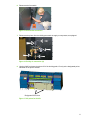
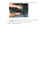
HP Scitex FB910 Printer Preparing the printer for transport 1 © 2012 Hewlett-Packard Development Company, L.P. The information contained herein is subject to change without notice. The only warranties for HP products and services are set forth in the express warranty statements accompanying such products and services. Nothing herein should be construed as constituting an additional warranty. HP shall not be liable for technical or editorial errors or omissions contained herein. Part number TN2808 Revision A 2 1 Overview There are three main areas that need to be attended to before moving the printer: 1. Preparation of the printheads 2. Preparation of the carriage 3. Preparation of the printer chassis 1.2 Printer orientation Figure 1 Printer orientation 1.3 Printhead orientation Figure 2 Printhead orientation 3 2 Printhead preparation This process empties all the ink from the printheads and consumes a quantity of printhead flush solution. Be prepared for proper disposal of the liquid wastes before moving the printer. Dispose of all liquid wastes in accordance with local regulations. IMPORTANT: The printheads have a very short lifespan if ink is removed from them. The printer move should be executed as speedily as possible to prevent permanent loss of jets. If the printer move will take a very short period of time (less than a few hours) it may not be necessary to empty the printheads of ink. Use a fully charged uninterruptible power supply (UPS) to provide battery power to the external 24VDC power supply for the ink delivery system (IDS) vacuum. If the duration of the printer move is too long to provide battery power to the IDS vacuum, then the ink must be emptied from the printheads before moving the printer. 2.1 Required tools and materials #2 Phillips screwdriver HP UV Printhead Flush, HP part number CH122A Small squeeze bottle or similar vessel to delivery flush to the printheads, such as HP part number CH154-67015 FRM,BOTTLE,FLUSH,Q. Figure 3 Squeeze bottle for flush, HP Part Number CH154-67015 Waste ink disposal container, such as HP part number CH154-67014 Figure 4 Waste ink collection bottle, HP Part number CH154-67014 A large funnel to facilitate emptying the serviced station tray into the waste ink container Lint-free cloths to wipe the printheads 4 2.2 Procedure 1. From the printer’s control panel, select “Tools | Maintenance | Printheads Procedures | Empty Heads (Fill with Air)”. Follow the on-screen prompts for the procedure. The procedure uses air pressure to empty the ink from the heads. The ink drains into the service station tray located at the user end of the printer. 2. Repeat step one until no more ink can be seen exiting the printheads. 3. Remove the carriage cover for access to the printheads. Figure 5 Carriage cover fastener locations 4. Wear protective gloves, such as latex, to protect your hands from being stained with ink. 5. Locate the left-slave printhead for each color channel. The left slave printhead has the air tube connection as shown in Figure 6. Figure 6 Air tubes (indicated by arrows) connecting to left-slave printheads 6. Remove the air tube from the left-slave printhead. 5 7. Locate the right-slave printhead for each color and remove the air U-tube as shown in Figure 7. Figure 7 Removal of air U-tube from right-slave printhead. Yellow is shown; repeat for all colors. 8. Insert the tip of the squeeze bottle into the vacuum-port barb (where the U-tube was disconnected) and fill the set of printheads with head flush. Continue filling the printheads with flush until the flush can be seen at the top of the vacuum port. Figure 8 Filling the printhead with flush 9. Repeat step 8 for all four sets of printheads. 10. Reconnect the air U-tube that was removed in step 7 and reconnect the air tube that was removed in step 6. 11. From the printer’s control panel, select “Tools | Maintenance | Printheads Procedures | Empty Heads (Fill with Air)”. Follow the on-screen prompts for the procedure. The procedure uses air pressure to empty the flush from the heads. The flush drains into the service station tray located at the user end of the printer. 12. Repeat steps 5-11 until the flush exiting the printheads appears clear and has no remnants of ink coloration. TIP: Check the level of waste liquid in the service station tray frequently and empty it as necessary to avoid an overflow. 13. Repeat step 11 until no more flush can be seen exiting the printheads. 14. Wipe the bottoms of the printheads using a lint-free cloth moistened with printhead flush. 15. Empty the service station tray of accumulated liquid wastes. The printheads are now prepared for transport. Power down the printer and prepare the carriage. 6 3 Carriage preparation The carriage must be isolated from the rail to prevent damage to both the rail and the carriage wheels. When the printer shipped new from the factory, the carriage was completely removed from the rest of the printer and packaged separately. If this packaging has been retained from the original shipment, and/or if the distance to be transported is large, it may be worth considering removing the carriage altogether. For shorter transport, this is not required and the carriage can be isolated and secured by the method described in this document. 3.1 Required tools and materials Lint-free cloths Two or more polyurethane foam pads approximately 12" x 18", ½" or 1" thick Liquid-absorbent pads such as PIG® Absorbent Mats or similar product Saran™ Wrap (genuine Saran brand recommended; other plastic films may react with the head flush) HP UV Printhead Flush, HP part number CH122A #3 Phillips screwdriver 3.2 Procedure 1. Ensure that all other printer preparations that require power have been completed. 2. If the move is short enough that ink has been left in the printheads, ensure that the auxiliary 24VDC power supply is connected and providing power to the IDS vacuum. 3. Power down the printer and disconnect from facility power. 4. If the carriage cover was removed as part of the printhead preparations, reinstall it now. 5. Move the carriage by hand to the center of the rail. 6. Using a #3 Phillips screwdriver, remove the primary screw (“A” in Figure 9) that secures the idler assembly to the rail. Figure 9 Idler assembly and fastener 7. Rotate the idler toward the output side of the printer so that it comes off the rail. The main blue carriage belt will still be in place and will keep the idler near the printer. Allow the idler to dangle loosely in front of the rail. 8. Place a piece of Saran Wrap slightly larger than the carriage on the media belt in front of the printer. 7 9. Place an absorbent pad on top of the Saran Wrap. The pad and the wrap are to prevent any seeping liquids from getting on the belt or into the vacuum table. 10. Place a foam pad onto of the Saran Wrap and absorbent pad. This foam pad is the primary cushioning for the carriage to rest upon. 11. Place another piece of Saran Wrap on top of the foam pad. 12. Place several lint-free cloths on the Saran Wrap/pad. 13. Apply a generous quantity of HP Printhead Flush to the lint-free cloths. 14. Carefully lift the carriage up and off of the rail and place it gently onto the lint-free cloths/Saran Wrap/foam pad construct on the belt, repositioning it as necessary to accommodate the carriage. 15. Place another piece of foam behind the carriage so that it is between the carriage and the belt. This foam pad is the primary cushioning to prevent the rail and the carriage wheels from damage. Use as much foam as necessary to fully separate the wheels and the rail. 16. Use shrink/stretch wrap, banding, or other appropriate restraining materials to immobilize the carriage and padding so that it cannot shift left to right nor bounce up and down. If metal or plastic banding is used, use foam sheets and/or cardboard shims to prevent the banding from digging in to printer components such as the belt or rail. The carriage is now prepared for transport. Continue with preparation of the printer chassis. 8 4 Chassis preparation 4.1 Required tools and materials Forklift with 45" long (about 144 cm) forks that span up to 42" (about 107 cm) wide 13mm wrenches (2) or sockets (2) Polyurethane foam blocks 2-3" thick Shrink/stretch wrap or other shipping materials Saran™ Wrap (genuine Saran brand recommended; other plastic films may react with the ink) Cable ties or rubber bands When properly installed, the printer rests on leveling pads. If the printer is to be moved entirely by forklift or other rigging, it may not be necessary to remove the pads and install the wheels. If wheels are necessary or desired for the move, the following is required: Printer wheels, quantity 4, HP Part number CH971-91440 FRM,PRNTR_WHEEL,L if the original wheels are no longer on hand. This kit includes one wheel and the necessary hardware to attach it to the printer. 4.2 Procedure 1. Disconnect the user-end and service-end enclosures from the rest of the printer. Figure 10 Service-end cable connections Figure 11 Service-end grounding strap (user end similar) 9 Figure 12 User-end cable connections to chassis 2. Remove the ink boxes (cartridges) and ink profilers the printer prior to transport. Be sure to keep the profilers with their respective cartridges. 3. Wrap the ends of each ink cartridge connector with Saran Wrap and secure with a rubber band or cable tie, to prevent ink from dripping out of the connectors. 4. Place foam blocks under the media hold-down rollers, using the roller cranks to adjust height as necessary. Figure 13 Foam blocks underneath the media hold-down rollers 5. Isolate the N-up alignment pins from the belt with foam or other protective material. Figure 14 N-up alignment pins 10 6. Disconnect the foot switch. Figure 15 Foot switch connection 7. Disconnect the printer from the facility pneumatic air supply or compressor, as equipped. Figure 16 Facility air connection (A) 8. Use the forklift to elevate the printer off of the leveling pads. Lift only at the designated points indicated on the printer chassis. Designated Lift Points Figure 17 Lift points for forklift 11 9. Use the 13mm wrenches or sockets to attach the wheels at the four corners of the printer. Figure 18 Wheel attachment 10. Rotate the leveling pads up so they will not interfere with the wheels, or remove them entirely from the printer. 11. When all four wheels are attached, the printer may be lowered onto them. The printer is now ready for transportation. 12