1
HP ProLiant BL e-Class
C-GbE Interconnect Switch
User Guide
February 2003 (Second Edition)
Part Number 263682-002
HP CONFIDENTIAL Codename: DeLorean Part Number: 263682-002 Last Saved On: 2/5/03 10:38 AM
© 2002, 2003 Hewlett-Packard Development Company, L.P.
Microsoft®, Windows®, and Windows NT® are U.S. registered trademarks of Microsoft Corporation.
Netscape Navigator is a U.S. trademark of Netscape Communications Corporation.
Hewlett-Packard Company shall not be liable for technical or editorial errors or omissions contained herein. The
information in this document is provided “as is” without warranty of any kind and is subject to change without
notice. The warranties for HP products are set forth in the express limited warranty statements accompanying such
products. Nothing herein should be construed as constituting an additional warranty.
Confidential computer software. Valid license from HP required for possession, use or copying. Consistent with
FAR 12.211 and 12.212, Commercial Computer Software, Computer Software Documentation, and Technical
Data for Commercial Items are licensed to the U.S. Government under vendor's standard commercial license.
HP ProLiant BL e-Class C-GbE Interconnect Switch User Guide
February 2003 (Second Edition)
Part Number 263682-002
HP CONFIDENTIAL Codename: DeLorean Part Number: 263682-002 Last Saved On: 2/5/03 10:38 AM
Contents
About This Guide
Technician Notes........................................................................................................................................ vii
Where to Go for Additional Help.............................................................................................................. viii
Telephone Numbers ............................................................................................................................ viii
Chapter 1
Introduction
Overview ................................................................................................................................................... 1-1
Additional References ............................................................................................................................... 1-1
ProLiant BL e-Class C-GbE Interconnect Switch..................................................................................... 1-2
Features ..................................................................................................................................................... 1-2
Enterprise Class Performance ............................................................................................................. 1-2
Interconnect Switch Redundancy ....................................................................................................... 1-3
Configuration and Management ......................................................................................................... 1-3
Diagnostic Tools ................................................................................................................................. 1-4
Interconnect Switch Architecture .............................................................................................................. 1-4
Integrated Administrator..................................................................................................................... 1-5
Interconnect Switch Modules ............................................................................................................. 1-5
Redundant Crosslinks ......................................................................................................................... 1-5
Redundant Paths to Server Blades ...................................................................................................... 1-5
Supported Technologies ............................................................................................................................ 1-6
Layer 2 Switching ............................................................................................................................... 1-6
IEEE 802.1Q-Based Virtual Local Area Network.............................................................................. 1-6
Spanning Tree Protocol....................................................................................................................... 1-6
Simple Network Management Protocol and Remote Monitoring....................................................... 1-7
Port Mirroring ..................................................................................................................................... 1-7
Port Trunking and Load Balancing..................................................................................................... 1-7
Trivial File Transfer Protocol Support................................................................................................ 1-7
Store and Forward Switching Scheme ................................................................................................ 1-7
IEEE 802.1p-Based Class of Service for Packet Prioritization........................................................... 1-8
Internet Group Management Protocol Snooping ................................................................................ 1-8
Dynamic Host Configuration Protocol or Bootstrap Protocol ............................................................ 1-8
Simple Network Time Protocol .......................................................................................................... 1-9
User Account Management................................................................................................................. 1-9
External Components ................................................................................................................................ 1-9
External Panel ..................................................................................................................................... 1-9
LED Indicators.................................................................................................................................. 1-10
HP ProLiant BL e-Class C-GbE Interconnect Switch User Guide
HP CONFIDENTIAL Codename: DeLorean Part Number: 263682-002 Last Saved On: 2/5/03 10:38 AM
iii
Contents
Chapter 2
Setting up and Installing the Interconnect Switch
Overview....................................................................................................................................................2-1
Installing Interconnect Switch Hardware...................................................................................................2-1
Installing a New Interconnect Tray in a New ProLiant BL e-Class Server Blade Enclosure .............2-2
Replacing an Existing Interconnect Tray ............................................................................................2-4
Replacing a Patch Panel Tray..............................................................................................................2-6
Planning the Interconnect Switch Configuration .......................................................................................2-8
Default Settings ...................................................................................................................................2-8
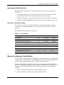
Interconnect Switch Security...............................................................................................................2-9
Manually Configuring a Switch Module .............................................................................................2-9
Configuring Multiple Switch Modules..............................................................................................2-10
Cabling the Interconnect Tray..................................................................................................................2-10
Configuring the Integrated Administrator................................................................................................2-13
Accessing the Switch Modules ................................................................................................................2-14
Supporting Software and Special Considerations ....................................................................................2-16
Appendix A
Regulatory Compliance Notices
Class A Equipment............................................................................................................................. A-1
Modifications...................................................................................................................................... A-1
Cables ................................................................................................................................................. A-1
Canadian Notice (Avis Canadien)............................................................................................................. A-1
Class A Equipment............................................................................................................................. A-1
European Union Notice............................................................................................................................. A-2
BSMI Notice ............................................................................................................................................. A-2
Japanese Notice......................................................................................................................................... A-2
Appendix B
Technical Specifications
Appendix C
Runtime Switching Software Default Settings
Default Settings......................................................................................................................................... C-1
Port Names, VLANs, STP/By Pass, Trunking Default Settings............................................................... C-5
Appendix D
Spanning Tree Protocol
Introduction............................................................................................................................................... D-1
Blocking State........................................................................................................................................... D-1
Listening State .......................................................................................................................................... D-2
Learning State ........................................................................................................................................... D-4
Forwarding State....................................................................................................................................... D-5
Disabled State ........................................................................................................................................... D-7
Troubleshooting STP ................................................................................................................................ D-9
Spanning Tree Protocol Failure.......................................................................................................... D-9
Full/Half Duplex Mismatch.............................................................................................................. D-10
Unidirectional Link .......................................................................................................................... D-11
iv
HP ProLiant BL e-Class C-GbE Interconnect Switch User Guide
HP CONFIDENTIAL Codename: DeLorean Part Number: 263682-002 Last Saved On: 2/5/03 10:38 AM
Contents
Packet Corruption ............................................................................................................................ D-12
Resource Errors................................................................................................................................ D-12
Identifying a Data Loop ................................................................................................................... D-12
Avoiding Trouble............................................................................................................................. D-13
Appendix E
SNMP/RMON MIBs Support
Introduction ............................................................................................................................................... E-1
SNMP Manager Software.......................................................................................................................... E-1
Standard MIBs........................................................................................................................................... E-2
Enterprise-Specific MIBs .......................................................................................................................... E-2
SNMP Traps .............................................................................................................................................. E-3
Appendix F
Upgrading Firmware through the Serial Port
Appendix G
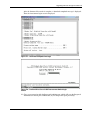
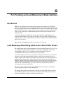
Port Trunking and Load Balancing in Blade Switches
Introduction .............................................................................................................................................. G-1
Load Balancing: Determining which Link to Send Traffic Across.......................................................... G-1
Default Settings for Load Balancing ........................................................................................................ G-2
Configuring Load Balancing on Blade Switches ..................................................................................... G-3
Hashing Algorithms for Load Balancing ................................................................................................. G-4
Redundancy: What Happens When One Link in the Port Trunk Fails?................................................... G-6
802.1Q Tagging/Trunking Supported on Port Trunks.............................................................................. G-6
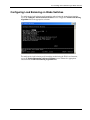
Appendix H
XML Configuration
Introduction .............................................................................................................................................. H-1
User Account Information........................................................................................................................ H-1
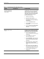
Safe Mode................................................................................................................................................. H-2
Interconnect Switch Replacement Scenario using a "Safe Mode" Configuration.................................... H-2
Safe Mode Configuration File Templates ................................................................................................ H-3
Safe Mode Configuration File Template Modification ............................................................................ H-3
Appendix I
Troubleshooting
Appendix J
RJ-45 Pin Specification
Index
HP ProLiant BL e-Class C-GbE Interconnect Switch User Guide
HP CONFIDENTIAL Codename: DeLorean Part Number: 263682-002 Last Saved On: 2/5/03 10:38 AM
v
About This Guide
This guide can be used for reference when servicing the HP ProLiant BL e-Class C-GbE
Interconnect Switch.
WARNING: To reduce the risk of personal injury from electric shock and hazardous
energy levels, only authorized service technicians should attempt to repair this
equipment. Improper repairs can create conditions that are hazardous.
Technician Notes
WARNING: Only authorized technicians trained by HP should attempt to repair this
equipment. All troubleshooting and repair procedures are detailed to allow only
subassembly/module-level repair. Because of the complexity of the individual boards
and subassemblies, no one should attempt to make repairs at the component level or
to make modifications to any printed wiring board. Improper repairs can create a safety
hazard.
WARNING: To reduce the risk of personal injury from electric shock and hazardous
energy levels, do not exceed the level of repairs specified in these procedures.
Because of the complexity of the individual boards and subassemblies, do not attempt
to make repairs at the component level or to make modifications to any printed wiring
board. Improper repairs can create conditions that are hazardous.
WARNING: To reduce the risk of electric shock or damage to the equipment:
•
Disconnect power from the system by unplugging all power cords from the power
supplies.
•
Do not disable the power cord grounding plug. The grounding plug is an important
safety feature.
•
Plug the power cord into a grounded (earthed) electrical outlet that is easily
accessible at all times.
CAUTION: To properly ventilate the system, you must provide at least 7.6 cm (3.0 in.) of
clearance at the front and back of the server.
CAUTION: The computer is designed to be electrically grounded (earthed). To ensure proper
operation, plug the AC power cord into a properly grounded AC outlet only.
HP ProLiant BL e-Class C-GbE Interconnect Switch User Guide
HP CONFIDENTIAL Codename: DeLorean Part Number: 263682-002 Last Saved On: 2/5/03 10:38 AM
vii
About This Guide
NOTE: Any indications of component replacement or printed wiring board modifications may void any
warranty.
Where to Go for Additional Help
In addition to this guide, the following information sources are available:
•
HP ProLiant BL e-Class C-GbE Interconnect Switch Menu-driven Interface Reference
Guide
•
HP ProLiant BL e-Class C-GbE Interconnect Switch Command Line Interface Reference
Guide
•
HP ProLiant BL e-Class C-GbE Interconnect Switch Web-based Interface Reference
Guide
•
Service Quick Reference Guide
•
Service training guides
•
Service advisories and bulletins
•
QuickFind information services
•
Insight Manager software
Telephone Numbers
For the name of your nearest HP authorized reseller:
•
In the United States, call 1-800-345-1518.
•
In Canada, call 1-800-263-5868.
For HP technical support:
•
In the United States and Canada, call 1-800-652-6672.
•
Outside the United States and Canada, refer to
www.hp.com
viii
HP ProLiant BL e-Class C-GbE Interconnect Switch User Guide
HP CONFIDENTIAL Codename: DeLorean Part Number: 263682-002 Last Saved On: 2/5/03 10:38 AM
1
Introduction
Overview
This user guide provides installation and reference information for the HP ProLiant
BL e-Class C-GbE Interconnect Switch.
Configuration and management information provided in this guide applies to interconnect
switches running firmware version 2.0.0 and higher and includes new features such as:
•
A command line interface (CLI) that provides standard scripting capabilities as well as
enhanced systems management and deployment
•
Simple Network Time Protocol (SNTP) capability that allows the GbE Interconnect
Switch to obtain the current date and time through a primary or secondary SNTP server
•
The capability to manually set the system time
•
Simple Network Management Protocol (SNMP) Management Information Base (MIB)
enhancements
Additional References
Once the interconnect switch is installed, you are ready to configure it. Detailed information
about how to configure the interconnect switch using the various user interfaces is available
in the following reference guides. These guides are located on the ProLiant BL e-Class CGbE Interconnect Switch Management System Utilities and User Documentation CD.
•
HP ProLiant BL e-Class C-GbE Interconnect Switch Menu-driven Interface Reference
Guide
•
HP ProLiant BL e-Class C-GbE Interconnect Switch Command Line Interface Reference
Guide
•
HP ProLiant BL e-Class C-GbE Interconnect Switch Web-based Interface Reference
Guide
HP ProLiant BL e-Class C-GbE Interconnect Switch User Guide
HP CONFIDENTIAL Codename: DeLorean Part Number: 263682-002 Last Saved On: 2/5/03 10:39 AM
1-1
Introduction
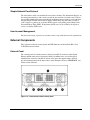
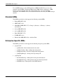
ProLiant BL e-Class C-GbE Interconnect Switch
The ProLiant BL e-Class C-GbE (Copper Gigabit Ethernet) Interconnect Switch uses
10/100/1000 Gigabit Layer 2 switch technology to provide up to a 40-to-1 reduction in the
number of networking cables required for each ProLiant BL e-Class server blade enclosure.
Each interconnect switch reduces forty 10Base-T/100Base-TX server networking ports to as
few as one (up to four) RJ-45 10Base-T/100Base-TX/1000Base-T uplink ports.
Figure 1-1: ProLiant BL e-Class C-GbE Interconnect Switch
Features
The ProLiant BL e-Class C-GbE Interconnect Switch is designed for easy installation and
high performance in an environment where traffic on the network and the number of users
increase continually.
Enterprise Class Performance
The ProLiant BL e-Class C-GbE Interconnect Switch features include:
•
Up to a 40-to-1 reduction in networking cables and connections by:
— Converting forty 10/100 Ethernet networking ports to as few as one (up to four)
Gigabit Ethernet networking ports.
— Allowing the use of only one of the four Gigabit Ethernet networking ports to
dramatically reduce the number of network cables required for a ProLiant BL e-Class
system.
— Allowing use of the remaining Gigabit Ethernet ports to fit the bandwidth
requirement.
— Providing redundant networking paths to each ProLiant BL e-Class server blade
through redundant switching modules.
1-2
•
Preconfiguration for immediate use with the ProLiant BL e-Class server blade enclosure
•
Industry standard protocols compatible with other widely-used networking components
•
Support for a total of 255 IEEE 802.1Q VLANs (including user configureable and/or
dynamic register), for server grouping and isolation
•
A variety of management interfaces
HP ProLiant BL e-Class C-GbE Interconnect Switch User Guide
HP CONFIDENTIAL Codename: DeLorean Part Number: 263682-002 Last Saved On: 2/5/03 10:39 AM
Introduction
•
Support for saving and downloading switch configurations to a TFTP server, thus
allowing for rapid deployment of multiple systems, and backup and restore capabilities
•
Uplink and management ports with link activity and speed indicators
•
Extra ports for management debugging and port mirroring
Interconnect Switch Redundancy
The ProLiant BL e-Class C-GbE Interconnect Switch offers several redundancy and failover
features. The interconnect switch can be configured for continued network access to each
server blade in case of system failure. Interconnect switch redundancy features include:
•
Two separate switch modules for each ProLiant BL e-Class C-GbE Interconnect Switch
•
Two Gigabit Ethernet uplink ports per switch module, with a total of four per
interconnect switch, for designing fully meshed uplink paths to the network backbone
•
Server networking connections routed to both switch modules for redundant paths to
tolerate a switch module or a port malfunction
•
Redundant data path 10/100 Ethernet cross connections between switch modules
•
Spanning Tree Protocol support which eliminates potential problems caused by redundant
networking paths and provides for failover with secondary path, in case of primary path
failure
•
Power and cooling by the redundant hot-plug power supplies and fans within the
ProLiant BL e-Class server blade enclosure
Configuration and Management
The ProLiant BL e-Class C-GbE Interconnect Switch provides the following configuration and
management interfaces and tools:
•
A command line interface (CLI) and a menu-driven interface allow local, Telnet, or
Serial Line Internet Protocol (SLIP) access.
•
A browser-based GUI allows remote access using a Web browser such as
Microsoft® Internet Explorer or Netscape Navigator.
•
Simple Network Management Protocol (SNMP) and Remote Monitoring (RMON)
manageability and monitoring are supported. An SNMP-based scripting utility allows
remote configuration of the GbE Interconnect Switch.
•
The interconnect switch functionality allows you to save and download interconnect
switch configurations to a TFTP server, thus allowing the rapid deployment of multiple
server blade systems, and providing robust backup and restore capabilities.
•
Simple Network Time Protocol (SNTP) is supported allowing the interconnect switch to
display and record the accurate date and time as provided by an SNTP server.
•
The interconnect switch functionality allows you to manually set the system time.
HP ProLiant BL e-Class C-GbE Interconnect Switch User Guide
HP CONFIDENTIAL Codename: DeLorean Part Number: 263682-002 Last Saved On: 2/5/03 10:39 AM
1-3
Introduction
Diagnostic Tools
The hardware, software, and firmware diagnostic tools that are available include:
•
ProLiant BL e-Class Integrated Administrator
•
Insight Manager 7
•
Power-On Self Test (POST) built into the interconnect switch boot-up process
•
C-GbE Interconnect Switch Management System and Utilities
•
C-GbE Interconnect Switch port mirroring
•
C-GbE Interconnect Switch LEDs for port status and speed
•
Medium Access Control (MAC)-based backdoor password provision (contact HP
technical support)
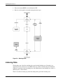
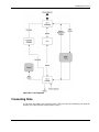
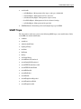
Interconnect Switch Architecture
The ProLiant BL e-Class C-GbE Interconnect Switch contains the ProLiant BL e-Class
Integrated Administrator module and two redundant interconnect switch modules (Switch A
and Switch B).
Figure 1-2: ProLiant BL e-Class C-GbE Interconnect Switch
architecture
1-4
HP ProLiant BL e-Class C-GbE Interconnect Switch User Guide
HP CONFIDENTIAL Codename: DeLorean Part Number: 263682-002 Last Saved On: 2/5/03 10:39 AM
Introduction
Integrated Administrator
The ProLiant BL e-Class Integrated Administrator provides centralized, remote management
and monitoring for the ProLiant BL e-Class server blade enclosure, interconnect switch
module, and 20 server blades. The Integrated Administrator acts as a combination terminal
server and remote power controller, enabling out-of-band, secure, serial console connections
to all server blades in the enclosure.
The Integrated Administrator serves as a single access point for administrative functions. It
provides remote and local setup, deployment, and administrative support, as well as
monitoring and health reporting of server blades, interconnect switch modules, and other
components in the enclosure, such as power supplies and fans.
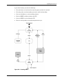
Interconnect Switch Modules
Two interconnect switch modules (Switch A and Switch B) in the interconnect switch
provide switch redundancy and redundant paths to the network ports on the server blades.
Each interconnect switch has two GB uplink ports and direct connections to one of the two
network interface cards (NICs) (NIC 1 and NIC 2) on each server blade. The interconnect
switch reduces as many as forty 10/100 Ethernet ports on the server blade into
as few as one (up to four) Gigabit uplink ports on the back of the system.
Redundant Crosslinks
The two interconnect switch modules are connected through redundant 100-Mb crosslinks.
These two crosslinks provide an aggregate throughput of 200 Mb for traffic between the
switch modules.
Redundant Paths to Server Blades
The NICs of each server blade are routed through the enclosure’s centerwall assembly to
different switch modules. By default, NIC 1 on each server blade is routed to Switch A and
NIC 2 on each server blade is routed to Switch B. This configuration provides redundant
paths to each server.
IMPORTANT: On a heavily used system, using a single uplink port for all 40 NICs can cause a traffic
bottleneck. For example, if uplink 1 on Switch A is the only uplink used, all traffic to and from NIC 2 on
any of the server blades must travel over the crosslinks between Switch A and Switch B. This path to
the server blade NICs is intended as a failover route and should not be used as a primary path. For
optimum performance, use uplink ports from both switch modules.
HP ProLiant BL e-Class C-GbE Interconnect Switch User Guide
HP CONFIDENTIAL Codename: DeLorean Part Number: 263682-002 Last Saved On: 2/5/03 10:39 AM
1-5
Introduction
Supported Technologies
The ProLiant BL e-Class C-GbE Interconnect Switch supports the following technologies.
Layer 2 Switching
The ProLiant BL e-Class C-GbE Interconnect Switch uses 10/100/1000 Gigabit Layer 2
switching technology. Layer 2 refers to the Data Link layer of the Open Systems
Interconnection (OSI) model, which is concerned with moving data packets across a network
by enforcing Carrier Sense Multiple Access with Collision Detection (CSMA/CD). This layer
performs:
•
Ethernet packet framing
•
MAC addressing
•
Physical medium transmission error detection
•
Medium allocation (collision avoidance)
•
Contention resolution (collision handling)
Layer 2 switch technology allows the interconnect switch to look into data packets and
redirect them based on the destination MAC address. This technology reduces traffic
congestion on the network, because packets, instead of being transmitted to all ports, are
transmitted to the destination port only.
IEEE 802.1Q-Based Virtual Local Area Network
The ProLiant BL e-Class C-GbE Interconnect Switch provides support for a total of 255
IEEE 802.1Q Virtual Local Area Networks (VLANs) (including user configurable and/or
dynamic registered), for server grouping and isolation. A VLAN is a network segment
configured according to a logical scheme rather than a physical layout. VLANs can be used
to combine any collection of LAN segments into an autonomous user group that appears as a
single LAN. VLANs also logically segment the physical network into different broadcast
domains so that packets are forwarded only between ports within the VLAN. This technology
enhances performance by conserving bandwidth and improves security by limiting traffic to
specific domains.
IMPORTANT: The greater the number of VLANs, the greater the interconnect switch CPU utilization.
For maximum interconnect switch performance, HP recommends that you be judicious when
configuring the number of VLANs.
Spanning Tree Protocol
The interconnect switch supports Spanning Tree Protocol (STP), which allows the blocking
of links that form loops between switches in a network. When multiple links between
switches are detected, a primary link is established. Duplicated links are blocked from use
and become standby links. If the primary link fails, the standby link is activated. Refer to
Appendix D for more information.
1-6
HP ProLiant BL e-Class C-GbE Interconnect Switch User Guide
HP CONFIDENTIAL Codename: DeLorean Part Number: 263682-002 Last Saved On: 2/5/03 10:39 AM
Introduction
Simple Network Management Protocol and Remote Monitoring
Each switch module can be configured and monitored remotely from a Simple Network
Management Protocol (SNMP)/Remote Monitoring (RMON) based Network Management
Station. The switch modules support industry-standard SNMP Management Information
Bases (MIBs), HP Switch MIBs, and RMON groups 1 (statistics), 2 (History), 3 (Alarm), and
9 (Event) for fault detection, configuration, and monitoring of switch functionality. In
addition, the interconnect switch supports various environmental traps such as temperature
and fan failure traps.
To secure the management interface, the switch administrator can configure community
strings with two levels of access. Access can be restricted to a limited number of
Management Stations by configuring a list of IP addresses of those stations that can access
the interconnect switch. Refer to Appendix E for more information.
Port Mirroring
The interconnect switch allows the user to mirror a port to another port for network
monitoring and troubleshooting purposes. This technology offers a way for network packet
analyzers to view the traffic moving through the switch modules by providing a copy of the
traffic that is currently being passed through any other port. The packets are normally sent to
a network packet analyzer or other monitoring device attached to the mirror port.
Port Trunking and Load Balancing
The interconnect switch port trunking feature allows several ports to be grouped together and
act as a single logical link called a trunk. This feature provides a bandwidth that is a multiple
of a single link’s bandwidth. It also improves reliability since a configurable type of load
balancing is automatically applied to the ports in the trunked group. A link failure within the
group causes the network traffic to be directed to the remaining links in the group.
Trivial File Transfer Protocol Support
The Trivial File Transfer Protocol (TFTP) service feature allows the interconnect switch
firmware to be upgraded by downloading a new firmware file from a TFTP server to the
switch modules. A configuration file can also be loaded into a switch module from a TFTP
server, configuration settings can be saved to the TFTP server, and a history log can be
uploaded from the switch module to the TFTP server.
Store and Forward Switching Scheme
The interconnect switch provides a store and forward switching scheme that allows each
packet to be buffered (stored) before it is forwarded to its destination. While this method
creates latency, it improves reliability in a heavily used interconnect switch. Packets that
cannot be forwarded are saved immediately, rather than dropped, and packets behind it are
less likely to be dropped in periods of heavy usage.
HP ProLiant BL e-Class C-GbE Interconnect Switch User Guide
HP CONFIDENTIAL Codename: DeLorean Part Number: 263682-002 Last Saved On: 2/5/03 10:39 AM
1-7
Introduction
IEEE 802.1p-Based Class of Service for Packet Prioritization
Class of Service (CoS) for packet prioritization allows switch administrators to set priority
levels on the interconnect switch for forwarding packets based on the priority setting
information in the packets. The interconnect switch supports four classes of traffic (buffers or
queues) for implementing priority. The interconnect switch allows administrators to map
eight priority levels to four classes. Traffic from a specific server port can be given priority
over packets from other devices according to this range of priority levels. For example, with
multiple packets in a buffer, the packet with the highest priority would be forwarded first,
regardless of when it was received.
Internet Group Management Protocol Snooping
Internet Group Management Protocol (IGMP) snooping, when enabled and configured
properly, manages multicast traffic in a switch module by allowing directed switching of the
IP multicast traffic. The interconnect switch can use IGMP snooping to configure switch
module ports dynamically, so that IP multicast traffic is forwarded only to those ports
associated with IP multicast hosts.
IGMP snooping allows the switch module to recognize IGMP queries and reports sent
between network stations or devices and an IGMP host that belongs to a specific multicast
group. When enabled for IGMP snooping, the switch module can open or close a port to a
specific device based on IGMP messages passing through the module. This feature further
limits unnecessary broadcasts. The GbE Interconnect Switch can be configured to use either
IGMP version 1 or version 2 when making queries
Dynamic Host Configuration Protocol or Bootstrap Protocol
A switch module can be configured to obtain an IP address from a Dynamic Host
Configuration Protocol (DHCP) or Bootstrap Protocol (BOOTP) server during the boot
process. By default, the interconnect switch is configured for DHCP. The IP settings can be
manually configured through the console interface. The IP settings are also configurable from
other interfaces, such as the Web, but since the connection is based on an IP address for these
interfaces, users have to reconnect with the newly assigned IP address.
1-8
HP ProLiant BL e-Class C-GbE Interconnect Switch User Guide
HP CONFIDENTIAL Codename: DeLorean Part Number: 263682-002 Last Saved On: 2/5/03 10:39 AM
Introduction
Simple Network Time Protocol
The interconnect switch can maintain the current date and time. This information displays on
the management interfaces and is used to record the date and time of switch events. Current
date and time information can be manually set on the interconnect swithc or can be obtained
through Simple Network Time Protocol (SNTP). SNTP allows the interconnect switch to
send a request to a primary or secondary SNTP server in each polling period asking for the
Greenwich Mean Time (GMT). If the primary SNTP server is not available, the request is
sent to a secondary SNTP server.
User Account Management
For increased security, separate user accounts can be set up with various levels of permission.
External Components
This section describes the external panel and LED indicators of the ProLiant BL e-Class
C-GbE Interconnect Switch.
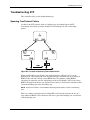
External Panel
The external panel of each interconnect switch has four RJ-45 connectors with Gigabit
Ethernet uplink connectivity for network cabling. In addition, there are two Integrated
Administrator connectors (one RJ-45 and one serial port) that support remote and local
out-of-band management of the interconnect switch through a browser, SNMP/RMON, and
Telnet console interfaces.
Figure 1-3: Interconnect switch external panel
HP ProLiant BL e-Class C-GbE Interconnect Switch User Guide
HP CONFIDENTIAL Codename: DeLorean Part Number: 263682-002 Last Saved On: 2/5/03 10:39 AM
1-9
Introduction
Table 1-1: Interconnect Switch External Panel
Item
Description
Location
1
Gigabit Ethernet port 26 connector on Switch B
Interconnect switch
2
Gigabit Ethernet port 25 connector on Switch B
Interconnect switch
3
Integrated Administrator management RJ-45
connector (Switch A Port 24—10/100 Ethernet)
Integrated Administrator module
4
Integrated Administrator console connector (serial)
Integrated Administrator module
5
Reserved for future use
Integrated Administrator module
6
Reserved for future use
Integrated Administrator module
7
Gigabit Ethernet port 26 connector on Switch A
Interconnect switch
8
Gigabit Ethernet port 25 connector on Switch A
Interconnect switch
9
Combined interconnect switch and Integrated
Administrator Reset button
Integrated Administrator module
CAUTION: Do not use the enclosure link (RJ-45) connectors (refer to items 5 and 6 in Table
1-1) on the Integrated Administrator module. Connecting an external device to these
enclosure link (RJ-45) connecters can damage the external device.
IMPORTANT: Resetting the interconnect switch disconnects the server blades from the network while
the switch is rebooting. To reset the interconnect switch, press the Reset button for at least four
seconds. To reset only the Integrated Administrator module, press the Reset button for less than four
seconds.
LED Indicators
The ProLiant BL e-Class C-GbE Interconnect Switch LEDs provide information about switch
health, link speed and activity, and stacking status.
1-10
HP ProLiant BL e-Class C-GbE Interconnect Switch User Guide
HP CONFIDENTIAL Codename: DeLorean Part Number: 263682-002 Last Saved On: 2/5/03 10:39 AM
Introduction
Figure 1-4: Interconnect switch external panel LEDs
Table 1-2: Interconnect Switch External Panel LEDs
Item
LED Description
Status
1
Integrated Administrator
module health
Green = Enclosure on, Integrated Administrator health good
Amber = Integrated Administrator health degraded
Red = Integrated Administrator health critical
Off = Enclosure off
2
Interconnect switch health
Green = Enclosure on, interconnect switch health good
Amber = Interconnect switch health degraded
Red = Interconnect switch health critical
Off = Enclosure off or booting
3
Reserved for future use
4
Link activity
Green = Network link
Flashing green = Network activity
Amber = Port disabled
Off = No network link
5
Link speed
Amber = 1000 Mb/s
Green = 100 Mb/s
Off = 10 Mb/s or no network link
HP ProLiant BL e-Class C-GbE Interconnect Switch User Guide
HP CONFIDENTIAL Codename: DeLorean Part Number: 263682-002 Last Saved On: 2/5/03 10:39 AM
1-11
2
Setting up and Installing the Interconnect Switch
Overview
This chapter describes how to set up and install the ProLiant BL e-Class C-GbE Interconnect
Switch and connect it to your network.
The setup and installation procedure includes the following tasks:
1. Installing the interconnect switch hardware
2. Planning the interconnect switch configuration
3. Cabling the interconnect tray to the network
4. Configuring the Integrated Administrator module
5. Accessing the switch modules
NOTE: The ProLiant e-Class C-GbE Interconnect tray consists of the ProLiant BL e-Class Integrated
Administrator module and two interconnect switch modules (Switch A and Switch B).
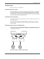
Installing Interconnect Switch Hardware
This section describes how to install the interconnect tray in a new switch deployment, as a
replacement for an existing interconnect switch, and as an upgrade from a patch panel.
HP ProLiant BL e-Class C-GbE Interconnect Switch User Guide
HP CONFIDENTIAL Codename: DeLorean Part Number: 263682-002 Last Saved On: 2/5/03 10:41 AM
2-1
Setting up and Installing the Interconnect Switch
Installing a New Interconnect Tray in a New ProLiant BL e-Class Server Blade
Enclosure
To install a new interconnect tray:
Figure 2-1: Removing a hot-plug power supply
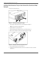
1. Press the port-colored latch to release one hot-plug power supply (1).
NOTE: Port-color indicates hot-plug components.
2. Pull the handle to its open position (2).
3. Slide the hot-plug power supply out of the server blade enclosure (3).
4. Repeat steps 1 through 3 to remove the other hot-plug power supply.
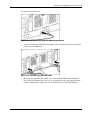
Figure 2-2: Pulling the interconnect tray ejector levers
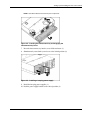
5. Press both interconnect tray release buttons (1).
6. Simultaneously pull both slate blue ejector levers toward the rear of the server blade
enclosure (2).
2-2
HP ProLiant BL e-Class C-GbE Interconnect Switch User Guide
HP CONFIDENTIAL Codename: DeLorean Part Number: 263682-002 Last Saved On: 2/5/03 10:41 AM
Setting up and Installing the Interconnect Switch
NOTE: Slate blue indicates internal touch point components.
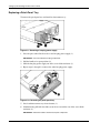
Figure 2-3: Inserting the interconnect tray and engaging the
interconnect tray levers
7. Insert the interconnect tray into the server blade enclosure (1).
8. Simultaneously rotate both ejector levers to the locked position (2).
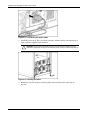
Figure 2-4: Installing a hot-plug power supply
9. Install the hot-plug power supplies (1).
10. Push the power supply handles to the closed position (2).
HP ProLiant BL e-Class C-GbE Interconnect Switch User Guide
HP CONFIDENTIAL Codename: DeLorean Part Number: 263682-002 Last Saved On: 2/5/03 10:41 AM
2-3
Setting up and Installing the Interconnect Switch
Replacing an Existing Interconnect Tray
To replace an existing interconnect tray:
1. Upload the current switch configuration to a TFTP server. Refer to the “Saving Settings
to a TFTP Server” section in the management interface reference guides.
IMPORTANT: HP recommends saving the switch module configuration to a TFTP server once the
switch module configuration is complete or has changed.
Figure 2-5: Removing a hot-plug power supply
2. Press the port-colored latch to release one hot-plug power supply (1).
IMPORTANT: Port-color indicates hot-plug components.
3. Pull the handle to its open position (2).
4. Slide the hot-plug power supply out of the server blade enclosure (3).
5. Repeat steps 2 through 4 to remove the other hot-plug power supply.
Figure 2-6: Removing the old interconnect tray
6. Press both interconnect tray release buttons (1).
2-4
HP ProLiant BL e-Class C-GbE Interconnect Switch User Guide
HP CONFIDENTIAL Codename: DeLorean Part Number: 263682-002 Last Saved On: 2/5/03 10:41 AM
Setting up and Installing the Interconnect Switch
7. Simultaneously pull both slate blue ejector levers toward the rear of the server blade
enclosure (2).
IMPORTANT: Slate blue indicates internal touch point components.
8. Pull the existing interconnect tray out of the server blade enclosure.
Figure 2-7: Inserting the new interconnect tray and engaging
the interconnect tray levers
9. Insert the new interconnect tray into the server blade enclosure (1).
10. Simultaneously rotate both ejector levers to the locked position (2).
Figure 2-8: Installing a hot-plug power supply
11. Install the hot-plug power supplies (1).
12. Push the power supply handles to the closed position (2).
13. Download the switch configuration file from the TFTP server. Refer to the
“Downloading Configuration File on a TFTP Server” section in the management
interface reference guides. If no configuration file is available, reconfigure the switch
modules.
HP ProLiant BL e-Class C-GbE Interconnect Switch User Guide
HP CONFIDENTIAL Codename: DeLorean Part Number: 263682-002 Last Saved On: 2/5/03 10:41 AM
2-5
Setting up and Installing the Interconnect Switch
Replacing a Patch Panel Tray
To remove the patch panel tray and install an interconnect tray:
Figure 2-9: Removing a hot-plug power supply
1. Press the port-colored latch to release one hot-plug power supply (1).
IMPORTANT: Port-color indicates hot-plug components.
2. Pull the handle to its open position (2).
3. Slide the hot-plug power supply out of the server blade enclosure (3).
4. Repeat steps 1 through 3 to remove the other hot-plug power supply.
Figure 2-10: Removing the patch panel tray
5. Press both interconnect tray release buttons (1).
6. Simultaneously pull both slate blue ejector levers toward the rear of the server blade
enclosure (2).
IMPORTANT: Slate blue indicates internal touch point components.
2-6
HP ProLiant BL e-Class C-GbE Interconnect Switch User Guide
HP CONFIDENTIAL Codename: DeLorean Part Number: 263682-002 Last Saved On: 2/5/03 10:41 AM
Setting up and Installing the Interconnect Switch
7. Pull the patch panel tray out of the server blade enclosure (3).
Figure 2-11: Inserting the interconnect tray and engaging the
interconnect tray levers
8. Insert the interconnect tray into the server blade enclosure (1).
9. Simultaneously rotate both ejector levers to the locked position (2).
Figure 2-12: Installing a hot-plug power supply
10. Install the hot-plug power supplies (1).
11. Push the power supply handles to the closed position (2).
HP ProLiant BL e-Class C-GbE Interconnect Switch User Guide
HP CONFIDENTIAL Codename: DeLorean Part Number: 263682-002 Last Saved On: 2/5/03 10:41 AM
2-7
Setting up and Installing the Interconnect Switch
Planning the Interconnect Switch Configuration
Before you configure the switch modules, HP recommends that you plan the configuration.
As you plan, keep in mind the default settings, security issues and privileges, and whether
you want to configure each switch module manually or configure multiple switch modules at
the same time.
Default Settings
IMPORTANT: Refer to Appendix C for detailed default configuration settings.
The interconnect switch ships with a default configuration with all ports (of both Switch A
and Switch B) enabled and assigned the same virtual LAN (VLAN). In addition, the
Integrated Administrator management connector (connected to internal port 23 of Switch A)
is assigned to the same default VLAN.
This default configuration simplifies your initial setup by allowing you to use a single uplink
cable (from any external Ethernet connector) to connect the server blade enclosure and its
server blades to your network. Keep in mind that your environment may require other
configurations.
When planning the configuration, consider the defaults for the following parameters:
2-8
•
Switch IP settings
•
Virtual Local Area Network (VLAN) and GARP VLAN Registration Protocol (GVRP)
settings
•
Spanning Tree Protocol (STP) settings
•
Port names and types
•
Port trunking settings
•
Class of Service (CoS) settings
•
Interswitch X-connect port settings
•
Simple Network Management Protocol (SNMP)/Remote Monitoring (RMON) settings
•
User name and password settings
•
Default access to various management interfaces
•
Internet Group Management Protocol (IGMP) Snooping settings
•
Simple Network Time Protocol (SNTP) settings
HP ProLiant BL e-Class C-GbE Interconnect Switch User Guide
HP CONFIDENTIAL Codename: DeLorean Part Number: 263682-002 Last Saved On: 2/5/03 10:41 AM
Setting up and Installing the Interconnect Switch
Interconnect Switch Security
When planning the configuration for a switch module, secure access to the management
interface by:
•
Creating users with various access levels to the local console, remote Telnet, and Web
interface. Refer to Table 2-1 for the three levels of user access privileges.
•
Enabling or disabling access to various management interfaces to fit the security policy.
•
Changing default SNMP/RMON community strings for read-only and read-write access.
Root, User+, and User Privileges
There are three levels of user privileges: Root, User+, and User. Some menu selections
available to users with Root privileges may not be available to those with User+ and User
privileges.
The following table summarizes user privileges.
Table 2-1: User Privileges
Privilege
Root
User+
User
Configuration
Yes
Read-only
Read-only
Network Monitoring
Yes
Read-only
Read-only
Community Strings and Trap Stations
Yes
Read-only
Read-only
Update Firmware and Configuration Files
Yes
No
No
System Utilities
Yes
Ping-only
Ping-only
Factory Reset
Yes
No
No
Reboot Switch
Yes
Yes
No
Add/Update/Delete User Accounts
Yes
No
No
View User Accounts
Yes
No
No
Manually Configuring a Switch Module
A switch module can be configured manually using a local console interface, a remote Telnet
console interface, a Web interface, or an SNMP interface. Refer to the management interface
reference guides for information on how to configure the switch modules.
After a switch module is configured, you can back up the configuration as a binary file to a
TFTP server. The backup configuration file can then be downloaded from the TFTP server to
restore the switch module back to the original configuration, under one of the following
conditions:
•
The switch module configuration gets corrupted during operation.
•
The switch module needs to be replaced due to hardware failure.
HP ProLiant BL e-Class C-GbE Interconnect Switch User Guide
HP CONFIDENTIAL Codename: DeLorean Part Number: 263682-002 Last Saved On: 2/5/03 10:41 AM
2-9
Setting up and Installing the Interconnect Switch
Configuring Multiple Switch Modules
You can configure multiple switch modules by using scripted Command Line Interface (CLI)
commands through Telnet or by downloading a configuration file using a TFTP server.
Using Scripted CLI Commands through Telnet
The CLI, provided with the interconnect switch, allows you to execute customized
configuration scripts on multiple switch modules. A configuration script can be tailored to
one of the multiple switch modules, and then that configuration can be deployed to other
switch modules from a central deployment sever.
Using a Configuration File
If you plan for the base configuration of multiple switch modules in your network to be the
same, you can manually configure one switch module, upload the configuration to a TFTP
server, and use that configuration file as a base configuration template. This base
configuration file can then be downloaded to multiple switch modules.
Small configuration changes can be pushed out to multiple switch modules by creating a
configuration file with just the configuration items desired. The configuration file can be
downloaded to each switch module needing the change. Refer to Appendix H, XML
Configuration, for additional information regarding the XML configuration file.
Switch module IP addresses are acquired by default using DHCP, therefore, each module has
a unique IP address. Each switch module can be remotely accessed from a central deployment
server and an individual switch module configuration can be downloaded to meet specific
network requirements. Refer to the management interface reference guides for more
information on using a TFTP server to upload and download configuration files.
Cabling the Interconnect Tray
After installing the interconnect switch hardware and planning the configuration, cable the
interconnect tray to your network.
CAUTION: In order to avoid damaging the server blade enclosure, observe the following
guidelines when cabling:
2-10
•
Connect the AC power cords last.
•
Be sure to connect both AC power cords for redundancy and proper cooling.
•
Bundle all cables and route them to the edge of the rack for proper cooling and airflow.
HP ProLiant BL e-Class C-GbE Interconnect Switch User Guide
HP CONFIDENTIAL Codename: DeLorean Part Number: 263682-002 Last Saved On: 2/5/03 10:41 AM
Setting up and Installing the Interconnect Switch
To cable the interconnect tray:
Figure 2-13: Connecting the Integrated Administrator module
1. Connect the Integrated Administrator module to your network by using the management
connector (10/100 Ethernet).
Figure 2-14: Connecting the network cables
2. Install the network cables. By default, each server blade has PXE enabled on Ethernet
Port 1. Since the Ethernet Port 1 of every server blade physically routes through Switch
A, HP recommends that either Port 25 or 26 of Switch A be used for PXE functions.
HP ProLiant BL e-Class C-GbE Interconnect Switch User Guide
HP CONFIDENTIAL Codename: DeLorean Part Number: 263682-002 Last Saved On: 2/5/03 10:41 AM
2-11
Setting up and Installing the Interconnect Switch
Figure 2-15: Connecting the power cables
3. Install the power cords. The server blade enclosure and interconnect switch power up as
soon as power is applied to the enclosure.
CAUTION: Because the server blade enclosure uses both power supplies for power
redundancy and proper cooling, be sure that both power cords are connected at all times.
Figure 2-16: Routing the cables
4. Bundle the network and power cables together and route them to the outer edge of
the rack.
2-12
HP ProLiant BL e-Class C-GbE Interconnect Switch User Guide
HP CONFIDENTIAL Codename: DeLorean Part Number: 263682-002 Last Saved On: 2/5/03 10:41 AM
Setting up and Installing the Interconnect Switch
Configuring the Integrated Administrator
After cabling the interconnect switch to your network, the next step is to configure the
Integrated Administrator module. The Integrated Administrator module enables monitoring
and managing of all functions within a server blade enclosure, as well as the ability to
configure the switch modules. After the switch modules are configured, the Integrated
Administrator module provides these features through both a Web-based user interface and a
command line interface.
You can connect to the Integrated Administrator module command-line interface locally or
remotely.
•
For local, out-of-band access, connect a null-modem cable into the serial port on the back
of the enclosure, and then use VT100 terminal emulation software to connect.
•
For remote access, you can use a Telnet or Secure Shell session to connect to the built-in
network controller.
NOTE: For complete instructions, refer to the HP ProLiant BL e-Class Integrated Administrator User
Guide on the Documentation CD provided with your server blade enclosure.
To configure the Integrated Administrator module:
1. Using the null-modem serial cable (provided with your server blade enclosure), connect
the Integrated Administrator (serial) console connector to a local client device such as a
laptop computer with VT100 terminal emulation software (such as
Microsoft® Windows® HyperTerminal).
Figure 2-17: Connecting the Integrated Administrator (serial)
console connector
2. Open a VT100 terminal emulation session with the following settings: 9600 baud rate,
eight data bits, no parity, one stop bit, and hardware flow control disabled.
3. Log on to the Integrated Administrator using the user name and password provided on the
tag attached to the interconnect tray. The tag contains a unique default password that
should be changed during your first logon session.
HP ProLiant BL e-Class C-GbE Interconnect Switch User Guide
HP CONFIDENTIAL Codename: DeLorean Part Number: 263682-002 Last Saved On: 2/5/03 10:41 AM
2-13
Setting up and Installing the Interconnect Switch
IMPORTANT: User name and password are case-sensitive.
4. Determine the Integrated Administrator IP address using one of the following methods:
NOTE: For more information, such as determining the Integrated Administrator IP address using
the Web-based user interface, refer to the HP ProLiant BL e-Class Integrated Administrator User
Guide on the Documentation CD provided with your server blade enclosure.
a. If a DHCP server is attached to the network, type the following at the command line
to determine the Integrated Administrator IP address:
show network
b. If a DHCP server is not attached to the network, then type the following commands
to assign a static IP address to the Integrated Administrator:
set ipconfig static <IP address> <subnet mask>
set gateway <IP address>
set DNS <primary DNS server address> {<secondary DNS server
address>}
restart
You may now access the Integrated Administrator module through a Web browser,
Secure Shell, Telnet, or SNMP connection.
5. Perform the following tasks as soon as the Integrated Administrator IP address is
assigned:
a. Reset the administrator password
b. Set the day, date, and time
c. Name the server blade enclosure and rack
d. Set up groups, users, and access privileges
Accessing the Switch Modules
After your ProLiant e-Class C-GbE Interconnect Switch is installed and cabled and the
Integrated Administrator is configured, you can access and configure the switch modules
through the Integrated Administrator software.
1. Access the switch modules from the Integrated Administrator command line interface
using one of the following methods:
a. If you have already logged into the Integrated Administrator as the “Administrator,”
you can connect to either switch module console using one of the following
commands:
connect switch a to access Switch A
or
connect switch b to access Switch B
2-14
HP ProLiant BL e-Class C-GbE Interconnect Switch User Guide
HP CONFIDENTIAL Codename: DeLorean Part Number: 263682-002 Last Saved On: 2/5/03 10:41 AM
Setting up and Installing the Interconnect Switch
b. If you have not logged on to the Integrated Administrator, you can use one of two
special logon accounts to access the switch module consoles directly, depending on
whether you want to access Switch A or Switch B. At the login prompt type in both
the user name and password as either:
switcha
or
switchb
The logon screen for Switch A or Switch B will now be displayed.
2. Perform the following tasks for each switch module:
a. Configure the IP address
b. Set up users, passwords, and access privileges
c. Change default SNMP community strings for read/write and read-only
NOTE: After configuring the IP address on the switch module, the switch module can be accessed
using Telnet, SNMP, or a Web browser.
Refer to the command line interface and menu-driven interface reference guides for
information on how to use the command line management interface and the menu-driven
interface to change configuration settings and monitor switch operation using one of the
following interfaces:
•
Local Serial RS-232 Console Management Interface through Integrated Administrator
•
Remote Telnet Console Management Interface
Refer to the Web-based interface reference guide for information on how to use the
embedded Web-based (HTML) interface to manage the interconnect switch from anywhere
on the network using a standard browser, such as Netscape Navigator or Microsoft Internet
Explorer.
Appendix E of this guide provides information regarding the SNMP and RMON Agents
along with the MIBs supported. This appendix also discusses how to use these MIBs to
configure and monitor the switch modules using a generic SNMP manager.
HP ProLiant BL e-Class C-GbE Interconnect Switch User Guide
HP CONFIDENTIAL Codename: DeLorean Part Number: 263682-002 Last Saved On: 2/5/03 10:41 AM
2-15
Setting up and Installing the Interconnect Switch
Supporting Software and Special Considerations
The following supporting software is available to assist you in configuring the interconnect
switch:
•
Utilities package and documentation—provides interconnect switch utilities, secure
replacement procedures, and information on scripting and firmware upgrades
•
Interconnect Switch Firmware Upgrade Smart Component (for Microsoft Windows
only)—Provides quick and easy installation of the interconnect switch firmware,
firmware upgrade tool, and readme file. A SoftPaq is available for use with Linux
operating systems
The preceding are located on the ProLiant BL e-Class C-GbE Interconnect Switch
Management System Utilities and User Documentation CD included with the interconnect
switch and at the following website:
www.compaq.com/support/servers
2-16
HP ProLiant BL e-Class C-GbE Interconnect Switch User Guide
HP CONFIDENTIAL Codename: DeLorean Part Number: 263682-002 Last Saved On: 2/5/03 10:41 AM
A
Regulatory Compliance Notices
Class A Equipment
This equipment has been tested and found to comply with the limits for a Class A digital
device, pursuant to Part 15 of the FCC Rules. These limits are designed to provide reasonable
protection against harmful interference when the equipment is operated in a commercial
environment. This equipment generates, uses, and can radiate radio frequency energy and, if
not installed and used in accordance with the instructions, may cause harmful interference to
radio communications. Operation of this equipment in a residential area is likely to cause
harmful interference, in which case the user will be required to correct the interference at
personal expense.
Modifications
The FCC requires the user to be notified that any changes or modifications made to this
device that are not expressly approved by Hewlett-Packard Company may void the user’s
authority to operate the equipment.
Cables
Connections to this device must be made with shielded cables with metallic RFI/EMI
connector hoods in order to maintain compliance with FCC Rules and Regulations.
Canadian Notice (Avis Canadien)
Class A Equipment
This Class A digital apparatus meets all requirements of the Canadian Interference-Causing
Equipment Regulations.
Cet appareil numérique de la classe A respecte toutes les exigences du Règlement sur le
matériel brouilleur du Canada.
HP ProLiant BL e-Class C-GbE Interconnect Switch User Guide
HP CONFIDENTIAL Codename: DeLorean Part Number: 263682-002 Last Saved On: 2/5/03 10:42 AM
A-1
Regulatory Compliance Notices
European Union Notice
Products bearing the CE marking comply with the EMC Directive (89/336/EEC) and the Low
Voltage Directive (73/23/EEC) issued by the Commission of the European Community and if
this product has telecommunication functionality, the R&TTE Directive (1999/5/EC).
Compliance with these directives implies conformity to the following European Norms (in
parentheses are the equivalent international standards and regulations):
•
EN 55022 (CISPR 22)—Electromagnetic Interference
•
EN55024 (IEC61000-4-2, 3, 4, 5, 6, 8, 11)—Electromagnetic Immunity
•
EN 60950 (IEC 60950)—Product Safety
BSMI Notice
Japanese Notice
A-2
HP ProLiant BL e-Class C-GbE Interconnect Switch User Guide
HP CONFIDENTIAL Codename: DeLorean Part Number: 263682-002 Last Saved On: 2/5/03 10:42 AM
B
Technical Specifications
Table B-1: General Specifications
Standards
IEEE 802.1D Spanning Tree
IEEE 802.1p QoS prioritization
IEEE 802.1Q VLAN
IEEE 802.3 10Base-T Ethernet
IEEE 802.3ab 1000Base-T Ethernet
IEEE 802.3ac Frame Extensions for VLAN
IEEE 802.3ad Link Aggregation Protocol (No
LACP support)
IEEE 802.3u 100Base-TX Fast Ethernet
IEEE 802.3x Full-Duplex Flow Control
ANSI/IEEE 802.3 Nway Auto-Negotiation
Protocols
CSMA/CD
Data Transfer Rates
Ethernet
Half-Duplex: 10-Mb/s
Full-Duplex: 20-Mb/s
Fast Ethernet
Half-Duplex: 100-Mb/s
Full-Duplex: 200-Mb/s
Gigabit Ethernet
Full-Duplex: 2000-Mb/s
continued
HP ProLiant BL e-Class C-GbE Interconnect Switch User Guide
HP CONFIDENTIAL Codename: DeLorean Part Number: 263682-002 Last Saved On: 2/5/03 11:15 AM
B-1
Technical Specifications
Table B-1: General Specifications continued
Network Cables
10Base-T
2 Pair UTP Category 3,4,5 (100 m)
EIA/TIA-568 100-ohm STP (100 m)
100Base-TX
2 Pair or 4 Pair UTP Category 5 (100 m)
EIA/TIA-568 100-ohm STP (100 m)
1000Base and 1000Base-T
4 Pair UTP Category 5e (100 m)
EIA/TIA-568 100-ohm STP (100 m)
Number of Ports
42—10/100-Mb/s Nway Ethernet Ports
4—10/100/1000 Base-T/TX/T Uplink
Ethernet Ports
1—Serial RS-232 Console Management Port
(through the Integrated Administrator)
1—10/100 Base T/TX Ethernet Management
Port (through the Integrated Administrator)
Table B-2: Physical and Environmental Specifications
DC Inputs
12V: 3.5A per switch module
5V: 0.3A per switch module
Power Consumption
50 watts maximum per switch module
Operating Temperature
0 to 50 degrees Celsius
Storage Temperature
-30 to 70 degrees Celsius
Operating Humidity
5% to 95% RH noncondensing
Storage Humidity
0% to 95% RH noncondensing
Dimensions
11.2 inches x 16.1 inches
Weight
620 grams (1.4 lb)
EMI
FCC Class A
CE Class A
VCCI Class A
Safety
UL/CUL
TUV/GS
B-2
HP ProLiant BL e-Class C-GbE Interconnect Switch User Guide
HP CONFIDENTIAL Codename: DeLorean Part Number: 263682-002 Last Saved On: 2/5/03 11:15 AM
Technical Specifications
Table B-3: Performance Specifications
Transmission Method
Store-and-forward
Memory
32MB Main, 8MB flash, and 16MB packet buffer
per switch module
Filtering Address Table
8K
Packet Filtering/Forwarding Rate
Full-wire speed for all connections.
148,809.5 pps per port (for 100-Mb/s)
1,488,095 pps per port (for 1000-Mb/s)
MAC Address Learning
Automatic update
Forwarding Table Age Time
Maximum Age: 10-9999 seconds
Default: 3000 seconds
Maximum Number of VLANs
255 (including default VLAN plus user
configurable and/or dynamic registered) per
switch module
HP ProLiant BL e-Class C-GbE Interconnect Switch User Guide
HP CONFIDENTIAL Codename: DeLorean Part Number: 263682-002 Last Saved On: 2/5/03 11:15 AM
B-3
C
Runtime Switching Software Default Settings
Default Settings
This section provides the default settings for the interconnect switch modules.
•
Table C-1 contains general default settings for both Switch Module A and Switch
Module B
•
Table C-2 contains Port Names, VLANs, STP/ByPass, Trunking Default Settings for
Switch Module A
•
Table C-3 contains Port Names, VLANs, STP/ByPass, Trunking Default Settings for
Switch Module B
Table C-1: Default Settings
Setting
Value
User Name
None
Password
None
DHCP Service
Enabled
BootP Service
Disabled
IP Address (if manual option is selected)
Switch A = 10.90.90.90
Switch B = 10.90.90.91
Subnet Mask (if manual option is selected)
255.0.0.0
Gateway (if manual option is selected)
0.0.0.0
Management VID
1
System Name
None
System Location
None
System Contact
None
Auto Logout
10 minutes
MAC Address Aging Time
300 seconds
IGMP Snooping—Globally
Disabled
Switch GVRP
Disabled
Telnet Status
Enabled
continued
HP ProLiant BL e-Class C-GbE Interconnect Switch User Guide
HP CONFIDENTIAL Codename: DeLorean Part Number: 263682-002 Last Saved On: 2/5/03 10:44 AM
C-1
Runtime Switching Software Default Settings
Table C-1: Default Settings continued
Setting
Value
Web Status
Enabled
Telnet/RS232 Interface
Menu
Group Address Filter Mode
Forward all unregistered
Scheduling Mechanism for CoS Queues
Strict
Trunk Load Sharing Algorithm
Src Address
Backpressure
Disabled
Port Speed/Duplex
Auto
Flow Control
On
Setup Restart Ingress Bandwidth
None
Setup Restart Egress Bandwidth
None
Switch STP
Enabled
Bridge Max Age
20 seconds
Bridge Hello Time
2 seconds
Bridge Forward Delay
15 seconds
Bridge Priority
32768
Port Priority
128
Port Cost
19 for ports 1-24
4 for ports 25-26
Static Unicast Filtering Table
None
Static Multicast Filtering Table
None
Static VLAN Entry
Default VLAN (VID = 1)
Port VID
1
Port Ingress Rule Filtering
Off
Port GVRP Setting
Off
IGMP Snooping—VLAN ID
1
IGMP Snooping—State
Enabled
IGMP Snooping—Querier State
Non-querier
IGMP Snooping—Robustness Variable
2
IGMP Snooping—Query Interval
125 seconds
IGMP Snooping—Max Response
10 seconds
Port Trunking
Xconnect (Port 21-22)
Port Mirroring—Source Port
1
Port Mirroring—Source Direction
Either (ingress and egress)
Port Mirroring—Target Port
11
continued
C-2
HP ProLiant BL e-Class C-GbE Interconnect Switch User Guide
HP CONFIDENTIAL Codename: DeLorean Part Number: 263682-002 Last Saved On: 2/5/03 10:44 AM
Runtime Switching Software Default Settings
Table C-1: Default Settings continued
Setting
Value
Port Mirroring—Mirror Status
Disabled
Broadcast Storm Monitoring
Disabled
Multicast Storm Monitoring
Disabled
DA Unknown Storm Monitoring
Disabled
Storm Threshold
500 packets/second
Port State
Enabled
Class of Service—Max Packets
10
Class of Service—Max Latency
0
Port Priority
0
Class of Traffic
Priority 0, 1: Class 0
Priority 4, 5: Class 2
Priority 2, 3: Class 1
Priority 6, 7: Class 3
Port Security—Admin State
Disabled
Port Security—Max Address
1
Port Security—Mode
DeleteOnReset
Priority MAC Address
None
SNMP Community String
•
public
•
private
•
public = read-only
•
private = read/write
SNMP Community String Access Right
SNMP Trap Manager IP
None
Security IP
0.0.0.0
User Account
None
TFTP Server IP Address
0.0.0.0
TFTP Port Number
69
Firmware Update
File name = none
Configuration File on TFTP Server
File name = none
Save Setting to TFTP Server
File name = none
Save History Log to TFTP Server
File name = none
PING Test
Target address = Undefined
Repeat = Infinite
continued
HP ProLiant BL e-Class C-GbE Interconnect Switch User Guide
HP CONFIDENTIAL Codename: DeLorean Part Number: 263682-002 Last Saved On: 2/5/03 10:44 AM
C-3
Runtime Switching Software Default Settings
Table C-1: Default Settings continued
Setting
Value
Serial Port Baud Rate
Fixed 115,200
VLAN Mode
IEEE 802.1Q
SNTP
Disabled
SNTP Server 1
0.0.0.0
SNTP Server 2
0.0.0.0
SNTP Poll Interval
720 seconds
Time Zone
-06.00
Daylight Saving Time (DST)
Disabled
Offset in Minutes
60 minutes
Boot Time
0 days 00 :00 :00
Current Time (System Uptime)
Unknown (based on the
elapsed time since boot)
Time Source
System Clock
C-4
HP ProLiant BL e-Class C-GbE Interconnect Switch User Guide
HP CONFIDENTIAL Codename: DeLorean Part Number: 263682-002 Last Saved On: 2/5/03 10:44 AM
Runtime Switching Software Default Settings
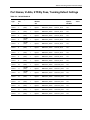
Port Names, VLANs, STP/By Pass, Trunking Default Settings
Table C-2: Switch Module A
Port
Type
UI
Port
#
Speed
VID
VLAN
Member
AS
VLAN Name
Port Name
STP /
ByPass
Enabled
Server
1
10/100
(Auto)
1
Egress
DEFAULT_VLAN
Server1_Port1
Yes
Server
2
10/100
(Auto)
1
Egress
DEFAULT_VLAN
Server2_Port1
Yes
Server
3
10/100
(Auto)
1
Egress
DEFAULT_VLAN
Server3_Port1
Yes
Server
4
10/100
(Auto)
1
Egress
DEFAULT_VLAN
Server4_Port1
Yes
Server
5
10/100
(Auto)
1
Egress
DEFAULT_VLAN
Server5_Port1
Yes
Server
6
10/100
(Auto)
1
Egress
DEFAULT_VLAN
Server6_Port1
Yes
Server
7
10/100
(Auto)
1
Egress
DEFAULT_VLAN
Server7_Port1
Yes
Server
8
10/100
(Auto)
1
Egress
DEFAULT_VLAN
Server8_Port1
Yes
Server
9
10/100
(Auto)
1
Egress
DEFAULT_VLAN
Server9_Port1
Yes
Server
10
10/100
(Auto)
1
Egress
DEFAULT_VLAN
Server10_Port1
Yes
Server
11
10/100
(Auto)
1
Egress
DEFAULT_VLAN
Server11_Port1
Yes
Server
12
10/100
(Auto)
1
Egress
DEFAULT_VLAN
Server12_Port1
Yes
Server
13
10/100
(Auto)
1
Egress
DEFAULT_VLAN
Server13_Port1
Yes
Server
14
10/100
(Auto)
1
Egress
DEFAULT_VLAN
Server14_Port1
Yes
Server
15
10/100
(Auto)
1
Egress
DEFAULT_VLAN
Server15_Port1
Yes
Server
16
10/100
(Auto)
1
Egress
DEFAULT_VLAN
Server16_Port1
Yes
Server
17
10/100
(Auto)
1
Egress
DEFAULT_VLAN
Server17_Port1
Yes
Port
Trunk
continued
HP ProLiant BL e-Class C-GbE Interconnect Switch User Guide
HP CONFIDENTIAL Codename: DeLorean Part Number: 263682-002 Last Saved On: 2/5/03 10:44 AM
C-5
Runtime Switching Software Default Settings
Table C-2: Switch Module A continued
Port Type
UI
Port
#
Speed
VID
VLAN
Member
AS
VLAN Name
Port Name
STP /
ByPass
Enabled
Server
18
10/100
(Auto)
1
Egress
DEFAULT_VLAN
Server18_Port1
Yes
Server
19
10/100
(Auto)
1
Egress
DEFAULT_VLAN
Server19_Port1
Yes
Server
20
10/100
(Auto)
1
Egress
DEFAULT_VLAN
Server20_Port1
Yes
X-Connect
21
10/100
(Auto)
1
Egress
DEFAULT_VLAN
XConnect1
No
XConnect
X-Connect
22
10/100
(Auto)
1
Egress
DEFAULT_VLAN
XConnect2
No
XConnect
IA NIC
23
10/100
(Auto)
1
Egress
DEFAULT_VLAN
IA Mgmt Module
Yes
Mgmt
Uplink
24
10/100
(Auto)
1
Egress
DEFAULT_VLAN
Mgmt Uplink
Yes
25
10/100
/1000
(Auto)
1
Egress
DEFAULT_VLAN
SwitchA_Uplink1
No
26
10/100
/1000
(Auto)
1
Egress
DEFAULT_VLAN
SwitchA_Uplink2
No
D Uplink
D Uplink
C-6
Port
Trunk
HP ProLiant BL e-Class C-GbE Interconnect Switch User Guide
HP CONFIDENTIAL Codename: DeLorean Part Number: 263682-002 Last Saved On: 2/5/03 10:44 AM
Runtime Switching Software Default Settings
Table C-3: Switch Module B
Port
Type
UI
Port
#
Speed
VID
VLAN
Member
AS
VLAN Name
Port Name
STP /
ByPass
Enabled
Server
1
10/100
(Auto)
1
Egress
DEFAULT_VLAN
Server1_Port2
Yes
Server
2
10/100
(Auto)
1
Egress
DEFAULT_VLAN
Server2_Port2
Yes
Server
3
10/100
(Auto)
1
Egress
DEFAULT_VLAN
Server3_Port2
Yes
Server
4
10/100
(Auto)
1
Egress
DEFAULT_VLAN
Server4_Port2
Yes
Server
5
10/100
(Auto)
1
Egress
DEFAULT_VLAN
Server5_Port2
Yes
Server
6
10/100
(Auto)
1
Egress
DEFAULT_VLAN
Server6_Port2
Yes
Server
7
10/100
(Auto)
1
Egress
DEFAULT_VLAN
Server7_Port2
Yes
Server
8
10/100
(Auto)
1
Egress
DEFAULT_VLAN
Server8_Port2
Yes
Server
9
10/100
(Auto)
1
Egress
DEFAULT_VLAN
Server9_Port2
Yes
Server
10
10/100
(Auto)
1
Egress
DEFAULT_VLAN
Server10_Port2
Yes
Server
11
10/100
(Auto)
1
Egress
DEFAULT_VLAN
Server11_Port2
Yes
Server
12
10/100
(Auto)
1
Egress
DEFAULT_VLAN
Server12_Port2
Yes
Server
13
10/100
(Auto)
1
Egress
DEFAULT_VLAN
Server13_Port2
Yes
Server
14
10/100
(Auto)
1
Egress
DEFAULT_VLAN
Server14_Port2
Yes
Server
15
10/100
(Auto)
1
Egress
DEFAULT_VLAN
Server15_Port2
Yes
Server
16
10/100
(Auto)
1
Egress
DEFAULT_VLAN
Server16_Port2
Yes
Server
17
10/100
(Auto)
1
Egress
DEFAULT_VLAN
Server17_Port2
Yes
Server
18
10/100
(Auto)
1
Egress
DEFAULT_VLAN
Server18_Port2
Yes
Port
Trunk
continued
HP ProLiant BL e-Class C-GbE Interconnect Switch User Guide
HP CONFIDENTIAL Codename: DeLorean Part Number: 263682-002 Last Saved On: 2/5/03 10:44 AM
C-7
Runtime Switching Software Default Settings
Table C-3: Switch Module B continued
Port Type
UI
Port
#
Speed
VID
VLAN
Member
AS
VLAN Name
Port Name
STP /
ByPass
Enabled
Server
19
10/100
(Auto)
1
Egress
DEFAULT_VLAN
Server19_Port2
Yes
Server
20
10/100
(Auto)
1
Egress
DEFAULT_VLAN
Server20_Port2
Yes
X-Connect
21
10/100
(Auto)
1
Egress
DEFAULT_VLAN
XConnect1
No
XConnect
X-Connect
22
10/100
(Auto)
1
Egress
DEFAULT_VLAN
XConnect2
No
XConnect
IA NIC
23
10/100
(Auto)
NA
NA
NA
NA
NA
Mgmt
Uplink
24
10/100
(Auto)
NA
NA
NA
NA
NA
25
10/100
/1000
(Auto)
1
Egress
DEFAULT_VLAN
SwitchB_Uplink1
No
26
10/100
/1000
(Auto)
1
Egress
DEFAULT_VLAN
SwitchB_Uplink2
No
D Uplink
D Uplink
C-8
Port
Trunk
HP ProLiant BL e-Class C-GbE Interconnect Switch User Guide
HP CONFIDENTIAL Codename: DeLorean Part Number: 263682-002 Last Saved On: 2/5/03 10:44 AM
D
Spanning Tree Protocol
Introduction
When Spanning Tree Protocol determines a port should be transitioned to the forwarding
state, the following occurs:
•
The port is put into the listening state where it receives Bridge Protocol Data Units
(BPDUs) and passes them to the GbE Interconnect Switch’s CPU.
•
If no BPDUs that suggest the port should go to the blocking state are received, the BPDU
packets from the CPU are processed
— The port waits for the expiration of the forward delay timer. The port then moves to
the learning state.
— In the learning state, the port learns station location information from the source
address of packets and adds this information to its forwarding database.
— The expiration of the forwarding delay timer moves the port to the forwarding state,
where both learning and forwarding are enabled. At this point, the port forwards
packets.
Blocking State
A port in the blocking state does not forward packets. When the switch is booted, a BPDU is
sent to each port in the switch putting these ports into the blocking state. A switch initially
assumes it is the root, and then begins the exchange of BPDUs with other switches. This will
determine which switch in the network is the best choice for the root switch. If there is only
one switch on the network, no BPDU exchange occurs, the forward delay timer expires, and
the ports move to the listening state. All STP enabled ports enter the blocking state following
switch boot.
A port in the blocking state does the following:
•
Discards packets received from the network segment to which it is attached.
•
Discards packets sent from another port on the switch for forwarding.
•
Does not add addresses to its forwarding database.
•
Receives BPDUs and directs them to the CPU.
HP ProLiant BL e-Class C-GbE Interconnect Switch User Guide
HP CONFIDENTIAL Codename: DeLorean Part Number: 263682-002 Last Saved On: 2/5/03 10:46 AM
D-1
Spanning Tree Protocol
•
Does not transmit BPDUs received from the CPU.
•
Receives and responds to network management messages.
Figure D-1: Blocking State
Listening State
The listening state is the first transition for a port from the blocking state. Listening is an
opportunity for the switch to receive BPDUs that may tell the switch that the port should not
continue to transition to the forwarding state, but should return to the blocking state (that is, a
different port is a better choice).
There is no address learning or packet forwarding from a port in the listening state.
D-2
HP ProLiant BL e-Class C-GbE Interconnect Switch User Guide
HP CONFIDENTIAL Codename: DeLorean Part Number: 263682-002 Last Saved On: 2/5/03 10:46 AM
Spanning Tree Protocol
A port in the listening state does the following:
•
Discards frames received from the network segment to which it is attached.
•
Discards packets sent from another port on the switch for forwarding.
•
Does not add addresses to its forwarding database.
•
Receives BPDUs and directs them to the CPU.
•
Processes BPDUs received from the CPU.
•
Receives and responds to network management messages.
Figure D-2: Listening State
HP ProLiant BL e-Class C-GbE Interconnect Switch User Guide
HP CONFIDENTIAL Codename: DeLorean Part Number: 263682-002 Last Saved On: 2/5/03 10:46 AM
D-3
Spanning Tree Protocol
Learning State
A port in the learning state prepares to participate in frame forwarding. The port enters the
learning state from the listening state.
A port in the learning state does the following:
D-4
•
Discards frames received from the network segment to which it is attached.
•
Discards packets sent from another port on the switch for forwarding.
•
Adds addresses to its forwarding database.
•
Receives BPDUs and directs them to the CPU.
•
Processes and transmits BPDUs received from the CPU.
•
Receives and responds to network management messages.
HP ProLiant BL e-Class C-GbE Interconnect Switch User Guide
HP CONFIDENTIAL Codename: DeLorean Part Number: 263682-002 Last Saved On: 2/5/03 10:46 AM
Spanning Tree Protocol
Figure D-3: Learning State
Forwarding State
A port in the forwarding state forwards packets. The port enters the forwarding state from the
learning state when the forward delay timer expires.
HP ProLiant BL e-Class C-GbE Interconnect Switch User Guide
HP CONFIDENTIAL Codename: DeLorean Part Number: 263682-002 Last Saved On: 2/5/03 10:46 AM
D-5
Spanning Tree Protocol
A port in the forwarding state does the following:
•
Forwards packets received from the network segment to which it is attached.
•
Forwards packets sent from another port on the switch for forwarding.
•
Incorporates station location information into its address database.
•
Receives BPDUs and directs them to the system CPU.
•
Receives and responds to network management messages.
Figure D-4: Forwarding State
D-6
HP ProLiant BL e-Class C-GbE Interconnect Switch User Guide
HP CONFIDENTIAL Codename: DeLorean Part Number: 263682-002 Last Saved On: 2/5/03 10:46 AM
Spanning Tree Protocol
Disabled State
A port in the disabled state does not participate in frame forwarding or STP. A port in the
disabled state is virtually non-operational.
A disabled port does the following:
•
Discards packets received from the network segment to which it is attached.
•
Discards packets sent from another port on the switch for forwarding.
•
Does not add addresses to its forwarding database.
•
Receives BPDUs, but does not direct them to the system CPU.
•
Does not receive BPDUs for transmission from the system CPU.
•
Receives and responds to network management messages.
HP ProLiant BL e-Class C-GbE Interconnect Switch User Guide
HP CONFIDENTIAL Codename: DeLorean Part Number: 263682-002 Last Saved On: 2/5/03 10:46 AM
D-7
Spanning Tree Protocol
Figure D-5: Disabled State
D-8
HP ProLiant BL e-Class C-GbE Interconnect Switch User Guide
HP CONFIDENTIAL Codename: DeLorean Part Number: 263682-002 Last Saved On: 2/5/03 10:46 AM
Spanning Tree Protocol
Troubleshooting STP
This section describes several troubleshooting tips.
Spanning Tree Protocol Failure
A failure in the STP generally leads to a bridging loop. A bridging loop in an STP
environment comes from a port that should be in the blocking state, but is forwarding
packets.
Figure D-6: Example of Spanning Tree Protocol failure
In this example, B has been elected as the designated bridge, and Port 2 on C is in the
blocking state. The election of B as the designated bridge is determined by the exchange of
BPDUs between B and C. B had a better BPDU than C. B continues sending BPDUs
advertising its superiority over the other bridges on this LAN. Should C fail to receive these
BPDUs for longer than the max age (default of 20 seconds), it could start to transition its Port
2 from the blocking state to the forwarding state.
NOTE: A port must continue to receive BPDUs advertising superior paths to remain in the blocking
state.
There are a number of circumstances in which STP can fail, mostly related to the loss of a
large number of BPDUs. These situations will cause a port in the blocking state to transition
to the forwarding state.
HP ProLiant BL e-Class C-GbE Interconnect Switch User Guide
HP CONFIDENTIAL Codename: DeLorean Part Number: 263682-002 Last Saved On: 2/5/03 10:46 AM
D-9
Spanning Tree Protocol
Full/Half Duplex Mismatch
A mismatch in the duplex state of two ports is a very common configuration error for a pointto-point link. If one port is configured as full-duplex, and the other port is left in autonegotiation mode, the second port will end up in half-duplex because ports configured as
half- or full-duplex do not negotiate.
Figure D-7: Example of full/half duplex mismatch
In the above example, Port 1 on B is configured as a full-duplex port, and Port 1 on A is
either configured as a half-duplex port, or left in auto-negotiation mode. Because Port 1 on B
is configured as a full-duplex port, it does not perform the carrier sense when accessing the
link. B will then start sending packets even if A is using the link. A will then detect collisions
and begin to run the flow control algorithm. If there is enough traffic between B and A, all
packets (including BPDUs) will be dropped. If the BPDUs sent from A to B are dropped for
longer than the max age, B will lose its connection to the root (A) and will unblock its
connection to C. This will lead to a data loop.
D-10
HP ProLiant BL e-Class C-GbE Interconnect Switch User Guide
HP CONFIDENTIAL Codename: DeLorean Part Number: 263682-002 Last Saved On: 2/5/03 10:46 AM
Spanning Tree Protocol
Unidirectional Link
Unidirectional links can be caused by an undetected failure in one side of a fiber cable, or a
problem with a ports transceiver. Any failure that allows a link to remain up while providing
one-way communication is very dangerous for STP.
Figure D-8: Example unidirectional link
In this example, Port 2 on B can receive but not transmit packets. Port 2 on C should be in the
blocking state, but since it can no longer receive BPDUs from Port 2 on B, it will transition to
the forwarding state. If the failure exists at boot, STP will not converge and rebooting the
bridges will have no effect.
This type of failure is difficult to detect because the link-state LEDs for Ethernet links rely on
the transmit side of the cable to detect a link. If a unidirectional failure on a link is suspected,
it is usually required to go to the console or other management software and look at the
packets received and transmitted for the port. For example, a unidirectional port will have
many packets transmitted but none received, or vice versa.
HP ProLiant BL e-Class C-GbE Interconnect Switch User Guide
HP CONFIDENTIAL Codename: DeLorean Part Number: 263682-002 Last Saved On: 2/5/03 10:46 AM
D-11
Spanning Tree Protocol
Packet Corruption
Packet corruption can also lead to Spanning Tree Protocol failure. If a link is experiencing a
high rate of physical errors, a large number of consecutive BPDUs can be dropped and a port
in the blocking state would transition to the forwarding state. The blocking port would have
to have the BPDUs are dropped for 50 seconds (at the default settings) and a single BPDU
would reset the timer. If the max age is set too low, this time is reduced.
Resource Errors
The ProLiant BL e-Class C-GbE Interconnect Switch performs its switching and routing
functions primarily in hardware, using specialized ASICs. STP is implemented in software
and is thus reliant upon the speed of the CPU and other factors in order to converge. If the
CPU is over-utilized, it is possible that BPDUs may not be sent in a timely fashion. STP is
generally not very CPU intensive and is given priority over other processes, so this type of
error is rare.
Very low values for the max age and the forward delay can result in an unstable Spanning
Tree. The loss of BPDUs can lead to data loops. The diameter of the network can also cause
problems. The default values for STP give a maximum network diameter of about seven
hops. This means that two switches in the network cannot be more than seven hops apart. Part
of this diameter restriction is the BPDU age field. As BPDUs are propagated from the root
bridge to the leaves of the spanning tree, each bridge increments the age field. When this field
is beyond the maximum age, the packet is discarded. For large diameter networks, STP
convergence can be very slow.
Identifying a Data Loop
Broadcast storms have a very similar effect on the network to data loops, but broadcast storm
controls in modern switches (along with subnetting and other network practices) have been
very effective in controlling broadcast storms. The best way to determine if a data loop exists
is to capture traffic on a saturated link and check if similar packets are seen multiple times.
Generally, if all the users of a given domain are having trouble connecting to the network at
the same time, a data loop can be suspected. The port utilization data in the switch’s console
will give unusually high values in this case.
The priority for most cases is to restore connectivity as soon as possible. The simplest remedy
is to manually disable all of the ports that provide redundant links. Disabling ports one at a
time, and then checking for a restoration of the user’s connectivity will identify the link that
is causing the problem, if time allows. Connectivity will be restored immediately after
disabling a data loop.
D-12
HP ProLiant BL e-Class C-GbE Interconnect Switch User Guide
HP CONFIDENTIAL Codename: DeLorean Part Number: 263682-002 Last Saved On: 2/5/03 10:46 AM
Spanning Tree Protocol
Avoiding Trouble
Below are some tips for avoiding trouble.
Know Where the Root is Located
Although the STP can elect a root bridge, a well-designed network will have an identifiable
root for each VLAN. Careful setup of the STP parameters will lead to the selection of this
best interconnect switch as the root for each VLAN. Redundant links can then be built into
the network. STP is well suited to maintaining connectivity in the event of a device failure or
removal, but is poorly suited to designing networks.
Know Which Links are Redundant
Organize the redundant links and tune the port cost parameter of STP to force those ports to
be in the blocking state.
For each VLAN, know which ports should be blocking in a stable network. A network
diagram that shows each physical loop in the network and the ports that break each loop is
extremely helpful.
Minimize the Number of Ports in the Blocking State
A single blocking port transitioning to the forwarding state at an inappropriate time can cause
a large part of a network to fail. Limiting the number of blocked ports helps to limit the risk
of an inappropriate transition.
Figure D-9: Example 1: A common network design
HP ProLiant BL e-Class C-GbE Interconnect Switch User Guide
HP CONFIDENTIAL Codename: DeLorean Part Number: 263682-002 Last Saved On: 2/5/03 10:46 AM
D-13
Spanning Tree Protocol
The above graphic is an example of a common network design. The switches C and D have
redundant links to the backbone switches A and B using trunks. Trunks, by default, carry all
the VLAN traffic from VLAN 1 and VLAN 2. So switch C is not only receiving traffic for
VLAN 1, but it is also receiving unnecessary broadcast and multicast traffic for VLAN 2. It is
also blocking one port for VLAN 2. Thus, there are three redundant paths between switches
A and B and two blocked ports per VLAN. This increases the chance of a data loop.
Figure D-10: Example 2: A common network design
In this example, the VLAN definitions are extended to switches A and B. This gives only a
single blocked port per VLAN and allows the removal of all redundant links by removing
switch A or B from the network.
D-14
HP ProLiant BL e-Class C-GbE Interconnect Switch User Guide
HP CONFIDENTIAL Codename: DeLorean Part Number: 263682-002 Last Saved On: 2/5/03 10:46 AM
E
SNMP/RMON MIBs Support
Introduction
Management and statistics information is stored in the interconnect switch in the
Management Information Base (MIB). The interconnect switch supports several standard
MIBs. Values for MIB objects can be retrieved with any SNMP-based network management
software.
In addition to the standard MIBs, the switch also supports its own proprietary enterprise MIB
as an extended Management Information Base. The proprietary MIB is retrieved by
specifying the MIB Object-Identifier (OID) at the network manager station.
MIB values can be either read-only or read/write variables.
•
Read-only MIB variables can be constants that are programmed into the switch or
variables that change while the switch is in operation. Examples of read-only constants
include the number and types of ports. Examples of read-only variables are the statistics
counters, such as the number of errors that have occurred or how many kilobytes of data
have been received and forwarded through a port.
•
Read/write MIB variables are usually related to user-customized configurations.
Examples include the IP address of the switch, Spanning Tree Algorithm parameters, and
port status.
SNMP Manager Software
If you use third-party vendor SNMP software to manage the switch, you can access
proprietary enterprise MIBs for the switch. The MIBs can be found on the ProLiant BL eClass C-GbE Interconnect Switch Management System Utilities and User Documentation CD
or with the interconnect switch utilities on the following website:
www.compaq.com/support/servers
If your software provides functions to browse or modify MIBs, you can also change the MIB
values (if the MIB attributes permit the write operation). This process can be quite involved,
however, because you must know the MIB OIDs and retrieve them one by one.
HP ProLiant BL e-Class E-GbE Interconnect Switch User Guide
HP CONFIDENTIAL Codename: DeLorean Part Number: 263682-002 Last Saved On: 2/5/03 10:48 AM
E-1
SNMP/RMON MIBs Support
Use an SNMP manager, such as HP OpenView or IBM Tivoli NetView, to access the
enterprise-specific MIBs. Compile the MIBs into the MIB database and then use a MIB
browser to navigate through them. For detailed information, access the individual
descriptions of each MIB or refer to the documentation that came with your SNMP manager
software.
Standard MIBs
The SNMP agent for the switch supports the following standard MIBs:
•
Bridge MIB (RFC 1493)
•
MIB-II (RFC 1213)
•
Mini-RMON MIB (RFC 1757)—Groups 1 (Statistics), 2 (History), 3 (Alarm),
and 9 (Event)
•
802.1p MIB (RFC 2674)
•
802.1q MIB (RFC 2674)
•
Entity MIB (RFC 2737)
•
IF-MIB (RFC 2233)
•
Ethernet-like MIB (RFC 2358)—dot3StatsTable
Enterprise-Specific MIBs
The SNMP agent for the switch supports the following enterprise-specific MIBs:
•
cpqAgent.mib
— agentBasicInfo—Basic information for the switch
— agentBasicConfig—Basic configuration management
— agentIpProtoConfig—IP-related configuration management
— agentIpTrapManager—Setting of the trap manager IP
•
cpql2mgt.mib
— swPortTrunkPackage—Management of the port trunk function
— swPortMirrorPackage—Management of the port mirroring function
— swIGMPPackage—Management of the IGMP function
E-2
HP ProLiant BL e-Class E-GbE Interconnect Switch User Guide
HP CONFIDENTIAL Codename: DeLorean Part Number: 263682-002 Last Saved On: 2/5/03 10:48 AM
SNMP/RMON MIBs Support
•
vesubio.mib
— swL2BwMgmt—Management of the ingress and egress bandwidth
— swL2CosMgmt—Management of Class of Service
— swL2PortSecurityMgmt—Management of port security
— dswL2DevMgmt—Management of device advanced settings
— swL2PortMgmt—Management of the port link
•
CIMTRAPS.mib—Redefining of the entConfigChange trap in SNMP
SNMP Traps
The interconnect switch may generate the following SNMP traps (event notifications). Refer
to the MIBs for detailed information.
•
coldStart
•
warmStart
•
authenticationFailure
•
topologyChange
•
newRoot
•
linkDown
•
linkUp
•
entConfigChange
•
switchFirmwareTransferred
•
switchConfigFileTransferred
•
switchTFTPTransferSucceeded
•
switchTFTPTransferFailed
•
switchFileInvalid
•
switchFanFailed
•
switchFanOk
•
switchTempSensorDegraded
•
switchTempSensorFailed
•
switchTempSensorOk
HP ProLiant BL e-Class E-GbE Interconnect Switch User Guide
HP CONFIDENTIAL Codename: DeLorean Part Number: 263682-002 Last Saved On: 2/5/03 10:48 AM
E-3
SNMP/RMON MIBs Support
E-4
•
switchPostSuccess
•
switchLoginFailure
•
switchLocationChange
•
switchCubeTypeChange
•
switchSNTPServiceUnavailable
HP ProLiant BL e-Class E-GbE Interconnect Switch User Guide
HP CONFIDENTIAL Codename: DeLorean Part Number: 263682-002 Last Saved On: 2/5/03 10:48 AM
F
Upgrading Firmware through the Serial Port
You can upgrade the system firmware of a switch module by connecting your computer to the
serial console port of the Integrated Administrator and using terminal emulation software that
supports the ZModem or XModem protocol. This procedure is only necessary if your
interconnect switch does not have access to a TFTP server, or if the firmware procedure was
previously interrupted and the switch module is not booting properly.
To download a firmware file to a switch module and change the external console port
baud rate:
1. From a PC using Microsoft® Windows® HyperTerminal or any other terminal emulation
program, connect to the serial console interface on the switch module at 9600 baud.
NOTE: For information on how to connect to the switch module menu-driven interface, refer to the
section “Connecting to the Switch Modules” in the menu-driven interface reference guide.
2. Reboot the switch module by using the Reboot menu option, or by pressing the
connection escape keys (usually Ctrl+Shift+_) and accessing the Integrated
Administrator Reboot Switch option. The boot procedure runs the Power-On Self-Test
(POST) and a screen similar to the following is displayed.
HP ProLiant BL e-Class C-GbE Interconnect Switch User Guide
HPCONFIDENTIAL Codename: DeLorean Part Number: 263682-002 Last Saved On: 2/5/03 10:50 AM
F-1
Upgrading Firmware through the Serial Port
Figure F-1: POST message
3. Press the pound (#) key as soon as you see the Boot Procedure header. This action
forces the switch module into the download mode. A screen similar to the following is
displayed.
Figure F-2: Download mode message
F-2
HP ProLiant BL e-Class C-GbE Interconnect Switch User Guide
HPCONFIDENTIAL Codename: DeLorean Part Number: 263682-002 Last Saved On: 2/5/03 10:50 AM
Upgrading Firmware through the Serial Port
4. Configure the download protocol (ZModem or XModem) or use the default boot
configuration settings.
a. Within 60-90 seconds, press the Ctrl+C keys to display the Boot Configuration
Menu.
b. To use the default boot configuration settings, go to step 9.
Figure F-3: Boot Configuration menu
5. Select XModem or ZModem as the download protocol.
6. Highlight Reboot.
7. Press the Enter key. The switch module reboots.
HP ProLiant BL e-Class C-GbE Interconnect Switch User Guide
HPCONFIDENTIAL Codename: DeLorean Part Number: 263682-002 Last Saved On: 2/5/03 10:50 AM
F-3
Upgrading Firmware through the Serial Port
8. While the switch module is rebooting, press the pound (#) key again to force the
switch module into download mode. The download mode message is displayed. (Refer to
Figure F-2.)
NOTE: For faster transfers, you may want to change the speed of your console connection from
9600 to 115200. If you continue to transfer at 9600, go to step 13.
9. Press the Integrated Administrator escape character <Ctrl>_. The following Integrated
Administrator connect menu is displayed:
-------------------------------------------------------------------------------------------------------Command: D)isconnect, C)hange settings, R)eboot Switch, E)xit
command mode >
-------------------------------------------------------------------------------------------------------10. Press the following keys in sequence to change the settings: C L C B I
Your screen displays the following lines:
-------------------------------------------------------------------------------------------------------Command: D)isconnect, C)hange settings, R)eboot Switch, E)xit
command mode > C
Change settings for: L)ocal Session, R)emote Port [Switch B],
E)xit > L
Change Local: C)ommunication Settings, D)isable Escape Character,
E)xit > C
Settings: B)audrate; flow control: N)one H)ardware S)oftware;
E)xit > B
Baud: A)1200 B)2400 C)4800 D)9600 F)19200 G)38400 H)57600
I)115200; E)xit > I
All communication setting changes are only temporary, and defaults
are restored at exit.
-------------------------------------------------------------------------------------------------------11. Change your local speed to 115200, and press the Enter key to continue.
12. Change the baud rate of your HyperTerminal session, and press the Enter key.
After the switch module is in the download mode and the baud rates are configured
properly, a connection-established message is displayed.
IMPORTANT: If the following screen displays nonsense characters, then a mismatched baud rate
configuration has occurred. Check HyperTerminal to see if the baud rate setting on the switch module
console interface and the HyperTerminal are mismatched.
F-4
HP ProLiant BL e-Class C-GbE Interconnect Switch User Guide
HPCONFIDENTIAL Codename: DeLorean Part Number: 263682-002 Last Saved On: 2/5/03 10:50 AM
Upgrading Firmware through the Serial Port
Figure F-4: Connection-established message
13. Before beginning the ZModem transfer, disable the Integrated Administrator escape
character to ensure a transparent connection for the file transfer. To disable this character,
press the following keys:
Ctrl+_ C L D
Your screen displays the following lines:
----------------------------------------------------------------Command: D)isconnect, C)hange settings, R)eboot Switch, E)xit
command mode > C
Change settings for: L)ocal Session, R)emote Port [Switch B],
E)xit >L
Change Local: C)ommunication Settings, D)isable Escape Character,
E)xit > D
The Escape Character <Ctrl>_ is now disabled.
you must
press <Ctrl>_ twelve times in sequence.
To re-enable it,
Press [Enter] to continue:
-----------------------------------------------------------------
14. Press the Enter key to continue.
HP ProLiant BL e-Class C-GbE Interconnect Switch User Guide
HPCONFIDENTIAL Codename: DeLorean Part Number: 263682-002 Last Saved On: 2/5/03 10:50 AM
F-5
Upgrading Firmware through the Serial Port
15. From the Interconnect Switch HyperTerminal window menu, select Transfer, then
Send File. The following window is displayed.
Figure F-5: Send File window
16. Click Browse and select the firmware file to be downloaded to the switch module.
17. Select the download protocol from the drop-down menu.
18. Press Send to start the download process. The following screen is displayed.
Figure F-6: ZModem file send for Interconnect Switch window
F-6
HP ProLiant BL e-Class C-GbE Interconnect Switch User Guide
HPCONFIDENTIAL Codename: DeLorean Part Number: 263682-002 Last Saved On: 2/5/03 10:50 AM
Upgrading Firmware through the Serial Port
After the firmware file transfer is complete, a download-completed message is displayed.
Then, the interconnect login screen is displayed.
Figure F-7: Download-completed message
Figure F-8: ProLiant BL e-Class C-GbE Interconnect Switch login
screen
19. Close your connection with the Integrated Administrator, which will reset the Integrated
Administrator console port to 9600 baud (if you changed the speed previously).
HP ProLiant BL e-Class C-GbE Interconnect Switch User Guide
HPCONFIDENTIAL Codename: DeLorean Part Number: 263682-002 Last Saved On: 2/5/03 10:50 AM
F-7
Upgrading Firmware through the Serial Port
20. Press Ctrl+_ twelve times in sequence to re-enable the escape character. The following
text is displayed:
----------------------------------------------------------------Command: D)isconnect, C)hange settings, R)eboot Switch, E)xit
command mode
-----------------------------------------------------------------
21. Press D to disconnect your session. If you changed the speed previously, you must reset
your terminal to 9600 baud to continue. The following text is displayed:
----------------------------------------------------------------Command: D)isconnect, C)hange settings, R)eboot Switch, E)xit
command mode > D
The console speed is being set back to 9600 bps.
Change your local speed back to 9600 and press [Enter] to continue
-----------------------------------------------------------------
22. Press Enter to close your connection to the switch module.
F-8
HP ProLiant BL e-Class C-GbE Interconnect Switch User Guide
HPCONFIDENTIAL Codename: DeLorean Part Number: 263682-002 Last Saved On: 2/5/03 10:50 AM
G
Port Trunking and Load Balancing in Blade Switches
Introduction
IEEE 802.3ad and EtherChannel compatible port trunks allow multiple physical Ethernet
links to be combined into one logical channel/trunk. This allows load sharing of traffic among
the links in the port trunk as well as redundancy in the event that one or more links in the port
trunk should fail. Port trunks can be used to interconnect local-area network (LAN) switches,
routers, servers, and clients via unshielded twisted-pair (UTP) wiring or single-mode and
multi-mode fiber.
A port trunk aggregates the bandwidth of up to eight compatibly configured ports into a
single logical link. Blade switches support a maximum of six port trunks. All Ethernet ports
support port trunks with no requirement that the ports be contiguous, but do require that they
must be the same speed.
NOTE: Dynamic Link Aggregation Control Protocol (LACP) is not supported.
Load Balancing: Determining which Link to Send Traffic Across
The load-balancing policy (frame distribution) can be based on MAC address (Layer 2). You
can configure these frame distribution policies to be based on source MAC address (SA),
destination MAC address (DA), or both source and destination MAC addresses
(SA XOR DA) in the frame to be forwarded across the port trunk.
A port trunk distributes frames across the links by reducing the last three lower order bits of
the binary pattern formed from the MAC addresses in the frame to a numerical value. In
addition, the port trunk calculates the modulus of that numerical value against the number of
available links in that port trunk, to determine which one of the links to send traffic across.
IEEE 802.3ad/Port trunk frame distribution policies are based on hashing algorithms that use
formulas mentioned below with examples. The algorithm is deterministic; given the same
addresses and session information, you always hash to the same port in the port trunk,
preventing out-of-order packet delivery.
The selected mode applies to all port trunks configured on the switch. Use the option that
provides the greatest variety in your configuration.
For example, if the traffic on a port trunk is going only to a single MAC address, using the
destination MAC address always chooses the same link in the port trunk; using the source
addresses or IP addresses might result in better load balancing.
HP ProLiant BL e-Class C-GbE Interconnect Switch User Guide
HP CONFIDENTIAL Codename: DeLorean Part Number: 263682-002 Last Saved On: 2/5/03 10:51 AM
G-1
Port Trunking and Load Balancing in Blade Switches
Circumstances can occur where one address in the source/destination pair is a constant. For
example, the destination might be a server or, even more likely, a router. In that case, if both
the source address and destination address option is selected, you will still see statistical load
balancing, because the source address is always different.
Default Settings for Load Balancing
The default four the interconnect switch is to use the source MAC address-based load
balancing. This means that all packets the switch receives on a non-trunk port with the same
source MAC address (SA), and that are destined to MAC addresses on the other side of the
port trunk, will use the same link in the port trunk. Source-based forwarding should be used
when many stations attached to the switch are sending to a few stations (such as a single
router) on the other side of the port trunk. This better distributes traffic across all links in the
port trunk.
Also, switches maintain a notion of a "primary" port on which to transmit traffic such as
Spanning Tree Protocol, multicasts, and unknown unicasts. The properties of this primary
port determine the properties of how the port trunk works with features like Spanning Tree,
VLAN, multicasting, and so on.
By default, XConnects between Switch A and Switch B in the chassis form a port trunk
“XConnect’ with two links, as shown in the following figure.
With source-MAC address forwarding, when packets are forwarded to a port trunk, they are
distributed across the ports in the port trunk based on the source-MAC address (SA) of the
incoming packet. Therefore, to provide load balancing, packets from different hosts use
different ports in the port trunk, but packets from the same host use the same port in the port
trunk.
With destination-MAC address forwarding, when packets are forwarded to a port trunk, they
are distributed across the ports in the port trunk based on the destination host's MAC address
(DA) of the incoming packet. Therefore, packets to the same destination are forwarded over
the same port, and packets to a different destination are sent on a different port in the port
trunk.
G-2
HP ProLiant BL e-Class C-GbE Interconnect Switch User Guide
HP CONFIDENTIAL Codename: DeLorean Part Number: 263682-002 Last Saved On: 2/5/03 10:51 AM
Port Trunking and Load Balancing in Blade Switches
Configuring Load Balancing on Blade Switches
To configure the load balancing and forwarding method using the menu-driven interface,
access the Configure Advanced Switch Features screen. Toggle the Trunk Load Sharing
Algorithm field to the appropriate selection.
To configure the load balancing and forwarding method using the Web-based interface,
access the Switch Information (Advanced Settings) screen. Choose the appropriate
selection in the Trunk Load Sharing Algorithm field.
HP ProLiant BL e-Class C-GbE Interconnect Switch User Guide
HP CONFIDENTIAL Codename: DeLorean Part Number: 263682-002 Last Saved On: 2/5/03 10:51 AM
G-3
Port Trunking and Load Balancing in Blade Switches
Hashing Algorithms for Load Balancing
The hashing algorithms use the last three least significant bits (LSB) of the destination MAC
address (DA), source MAC address (SA), or destination and source MAC address (DA XOR
SA) and the number of links that are available to forward frames in that port trunk group as
operators.
There are three algorithms that are supported to decide the outgoing port of frames,
depending on how the load balancing option is configured.
1. For the source MAC address option, N = (Last three LSB of SA) MOD (Number of links
up in the port trunk)
2. For the destination MAC address option, N = (Last three LSB of DA) MOD (Number of
links up in the port trunk).
3. For both source and destination MAC addresses option, N = (Last three LSB of DA XOR
SA) MOD (Number of links up in the port trunk).
If N is the remainder of the equation and N is not equal to 0, then the Nth link that is up in the
port trunk is the outgoing port. If N is the remainder of the equation and N is equal to 0, then
N + 1 link that is up in the port trunk is the outgoing port.
G-4
HP ProLiant BL e-Class C-GbE Interconnect Switch User Guide
HP CONFIDENTIAL Codename: DeLorean Part Number: 263682-002 Last Saved On: 2/5/03 10:51 AM
Port Trunking and Load Balancing in Blade Switches
For example: There is a port trunk group with eight member ports, and there is a frame with
SA=0x0080C800000B DA=0x0080C800000C.
•
SA last three bits is 0b011
•
DA last three bits is 0b100
•
SA XOR DA is 0b111
In the following example, four trunk ports are link up in the port trunk.
•
For algorithm 1, N = 0b011 MOD 4 = 3
The outgoing port would be the fourth link up in the port trunk.
•
For algorithm 2, N = 0b100 MOD 4 = 0
The outgoing port would be the first link up in the port trunk.
•
For algorithm 3, N = 0b111 MOD 4 = 3
The outgoing port would be the fourth link up in the port trunk.
The following table shows the relationship between the remainder and outgoing ports
Link up port
1st
2nd
3rd
4th
5th
6th
7th
8th
Last three LSB
0b000
0b001
0b010
0b011
X
X
X
X
Last three LSB
0b100
0b101
0b110
0b111
X
X
X
X
In the following example, 6 trunk ports are link up in the port trunk.
•
For algorithm 1, N = 0b011 MOD 6 = 3
The outgoing port would be the fourth link up in the port trunk.
•
For algorithm 2, N = 0b100 MOD 6 = 4
The outgoing port would be the fifth link up in the port trunk.
•
For algorithm 3, N = 0b111 MOD 6 = 1
The outgoing port would be the second link up in the port trunk.
The following table shows the relationship between the remainder and outgoing ports.
Link up port
1st
2nd
3rd
4th
5th
6th
7th
8th
Last three LSB
0b000
0b001
0b010
0b011
0b100
0b101
X
X
Last three LSB
0b110
0b111
X
X
X
X
X
X
HP ProLiant BL e-Class C-GbE Interconnect Switch User Guide
HP CONFIDENTIAL Codename: DeLorean Part Number: 263682-002 Last Saved On: 2/5/03 10:51 AM
G-5
Port Trunking and Load Balancing in Blade Switches
Redundancy: What Happens When One Link in the Port Trunk
Fails?
If a segment within the port trunk fails, traffic previously carried over the failed link switches
to the remaining segments within the port trunk. Inbound broadcast and multicast packets on
one segment in a port trunk are blocked from returning on any other segment of the port
trunk.
802.1Q Tagging/Trunking Supported on Port Trunks
In a port trunk, member ports can be configured with or without IEEE 802.1Q
trunking/tagging if they are members of a VLAN. After a port trunk is formed, configuring
the primary/first port in that port trunk as tagged applies the configuration to all remaining
ports in that port trunk. Similarly, configured trunk ports can be configured as a port trunk.
802.1Q encapsulation, if enabled, takes place independently of the source/destination loadbalancing mechanism of a port trunk. The virtual LAN (VLAN) ID has no bearing on which
link a packet takes. 802.1Q simply enables that trunk to belong to multiple VLANs. If
trunking is not enabled, all ports associated with the port trunk must belong to the same
VLAN.
G-6
HP ProLiant BL e-Class C-GbE Interconnect Switch User Guide
HP CONFIDENTIAL Codename: DeLorean Part Number: 263682-002 Last Saved On: 2/5/03 10:51 AM
H
XML Configuration
Introduction
Beginning in firmware version 2.0.0, interconnect switch firmware configuration files are
specified in eXtensible Markup Language (XML) format. In previous versions, the
configuration file was stored in binary format. Binary configuration files saved from previous
versions cannot be downloaded into firmware version 2.0.0. However, previous configuration
settings are preserved during the firmware upgrade to version 2.0.0.
Trivial File Transfer Protocol (TFTP) services continue to be used to upload and download
configuration files. See the TFTP sections in the Web-based, CLI, or menu-driven interface
reference guides.
When XML formatted configuration files are downloaded to the interconnect switch, the
interconnect switch interprets the contents and applies it to the system immediately. The
configuration settings are saved to NVRAM and become the current settings for the
interconnect switch. These settings are then used every time the interconnect switch is
rebooted.
IMPORTANT: The TFTP server must be running TFTP server software to perform a file transfer. TFTP
server software is included as part of the Windows utilities package.
User Account Information
User account information is not saved in the XML configuration file for security reasons and
must be managed by the interconnect switch administrator. User account information can be
manually added to the XML configuration file after it is uploaded, or it can be
re-entered using the CLI, menu-driven interface, or Web-based interface.
“root” is a special user name and is preserved even if <USER_ACCOUNTS_LIST
RESET="True">. Any other user name, such as “Administrator” with root privileges is
deleted along with all other users.
HP ProLiant BL e-Class GbE Interconnect Switch User Guide
HP CONFIDENTIAL Codename: DeLorean Part Number: 263682-002 Last Saved On: 2/5/03 10:52 AM
H-1
XML Configuration
Safe Mode
When inserting a new or replacement interconnect switch into a production environment, you
must be certain that the interconnect switch configuration is compatible with the production
network. Compatibility with a network can include items such as:
•
Non-corruption of the network in general—Corruption, such as loops, can occur within
the network without enabling Spanning Tree Protocol (STP).
•
Security of connected network entities—Security issues can arise as a result of
configuration items, including such attributes as subnet-to-subnet communication and
blade-to-blade communication where communication between these entities is not
acceptable.
•
Security of the interconnect switch itself—These attributes include controlled access to
the interconnect switch such as user-password and SNMP read-write community string.
•
Other configuration attributes such as VLAN settings.
The interconnect switch factory default, as well as previously configured interconnect
switches, may not have configurations that are compatible with the production network.
If the configuration of the interconnect switch is not compatible with the production network,
the interconnect switch may be pre-configured in a private network environment
There are several preconfiguration options. For example, the interconnect switch may be
configured for its exact position in the production network. Another option is to partially
configure the interconnect switch so that is is compatible with multiple positions in the
production network. The configuration can then be completed for the interconnect switch
through scripting, manual operation, or a configuration download. This more globally
appropriate configuration is called a "safe mode" configuration. Note that a single safe mode
configuration may or may not be appropriate for all production environments. A spare
interconnect switch, however, configured to a "safe mode" may be appropriate for multiple
production environments.
Interconnect Switch Replacement Scenario using a "Safe
Mode" Configuration
When an in-production interconnect switch fails:
1. Remove the failed interconnect switch.
2. Insert the spare interconnect switch that was previously configured for safe operation.
3. Upgrade to new firmware if appropriate.
4. Download the correct configuration for that particular interconnect switch.
H-2
HP ProLiant BL e-Class GbE Interconnect Switch User Guide
HP CONFIDENTIAL Codename: DeLorean Part Number: 263682-002 Last Saved On: 2/5/03 10:52 AM
XML Configuration
Safe Mode Configuration File Templates
Two example template configuration files have been provided as a basis to create an
appropriate safe mode configuration. Each file is delivered with the Switch Management
Utilities package specific to a particular type of interconnect switch.
•
esafe_ex.xml
•
psafe_ex.xml
NOTE: The templates provided are only examples, and should not be used in a production
environment without modifications rquired for your specific production network. These templates have
commented sections for IP configuration, password protection, and port selection.
Safe Mode Configuration File Template Modification
Copy the example “Safe Mode” template to a new name. Perform modifications appropriate
for your production environment. While the list below describes some of the most common
modifications, your environment may require additional settings such as VLAN
configuration. These basic areas are preceded by comments that include “SM:”. Use an editor
such as WordPad or a standard Linux editor.
•
Change the following settings if “Manual” IP settings are required.
<!--
-->
<!-- SM: Change the following settings if “Manual” IP settings are
required. -->
<IP_ADDRESS>
<GET_IP_FROM VALUE="DHCP"/>
<IP_ADDRESS VALUE="10.90.90.90"/>
<SUBNET_MASK VALUE="255.0.0.0"/>
<DEFAULT_GATEWAY VALUE="0.0.0.0"/>
<MANAGEMENT_VID VALUE="1"/>
</IP_ADDRESS>
HP ProLiant BL e-Class GbE Interconnect Switch User Guide
HP CONFIDENTIAL Codename: DeLorean Part Number: 263682-002 Last Saved On: 2/5/03 10:52 AM
H-3
XML Configuration
•
Change the following settings to match the remote TFTP server.
<!--
-->
<!-- SM: Change the following settings to match the remote TFTP
server -->
<TFTP_SETTINGS>
<SERVER_PORT_NUMBER VALUE="69"/>
<SERVER_IP VALUE="10.90.90.90"/>
<FIRMWARE_FILE_PATH VALUE="yourfirmware.bin"/>
<HISTORY_LOG_FILE_PATH VALUE=""/>
<CONFIGURATION_FILE_PATH VALUE="yoursparecfg.xml"/>
</TFTP_SETTINGS>
•
Port 19 has been left Enabled on p-Class interconnect switches (port 23 on e-Class). This
port may be Disabled and another Enabled per your environment. Multiple uplink ports
may be Enabled.
<PORT_CONFIGURATION VALUE="23">
<NAME VALUE="IA Mgmt Module"/>
<STATE VALUE="Enabled"/>
<FLOW_CONTROL VALUE="Enabled"/>
<SPEED VALUE="Auto"/>
<PRIORITY VALUE="0"/>
<RESTART_EGRESS_BANDWIDTH_IN_UNITS VALUE="0"/>
<RESTART_INGRESS_BANDWIDTH_IN_UNITS VALUE="0"/>
<STP_PORT_SETTINGS>
<PRIORITY VALUE="128"/>
<COST VALUE="19"/>
<BYPASS VALUE="Yes"/>
<STATE VALUE="Enabled"/>
</STP_PORT_SETTINGS>
<PORT_VLAN>
<PVID VALUE="1"/>
<INGRESS VALUE="Off"/>
<GVRP VALUE="Off"/>
</PORT_VLAN>
<SECURITY>
<MAX_LEARNING_ADDRESS VALUE="1"/>
<MODE VALUE="DeleteOnTimeout"/>
<STATE VALUE="Disabled"/>
</SECURITY>
</PORT_CONFIGURATION>
H-4
HP ProLiant BL e-Class GbE Interconnect Switch User Guide
HP CONFIDENTIAL Codename: DeLorean Part Number: 263682-002 Last Saved On: 2/5/03 10:52 AM
XML Configuration
•
You may wish to allow only a single IP address (management station) access.
<SECURITY_IP_ACCESS_LIST RESET="True">
<!--
-->
<!-- SM: Add an item for each management station that can access
the switch -->
<!-- SM: Example: <IPACCESS VALUE="192.168.0.1"/>
-->
</SECURITY_IP_ACCESS_LIST>
•
Change the read-write community string per your environment.
<!--
-->
<!-- SM: Change the read-write community string per your
environment. -->
<SNMP_ACCESS_LIST RESET="True">
<SNMP_ACCESS_ITEM COMMUNITY="public">
<TYPE VALUE="RO"/>
<STATUS VALUE="Valid"/>
</SNMP_ACCESS_ITEM>
<SNMP_ACCESS_ITEM COMMUNITY="yoursnmprw">
<TYPE VALUE="RW"/>
<STATUS VALUE="Valid"/>
</SNMP_ACCESS_ITEM>
</SNMP_ACCESS_LIST>
•
Set up the root user account, which will be used to complete the interconnect switch
configuration.
<!--
-->
<!-- SM: Change the root user for reconfiguration
-->
<!-- SM: Change per your environment.
-->
<!--
SET USER ACCOUNTS to BIOS DEFAULTS if RESET is True.-->
<!-- Remove the comment sign pairs, then add or modify user
accounts.
-->
<!--
Notice : ACCESS VALUE must be Root/User+/User.
-->
<USER_ACCOUNTS_LIST RESET="True">
<USER_ACCOUNT_ITEM USER="yourUser">
<PASSWORD VALUE="yourPassword"/>
<ACCESS VALUE="Root"/>
</USER_ACCOUNT_ITEM>
</USER_ACCOUNTS_LIST>
HP ProLiant BL e-Class GbE Interconnect Switch User Guide
HP CONFIDENTIAL Codename: DeLorean Part Number: 263682-002 Last Saved On: 2/5/03 10:52 AM
H-5
I
Troubleshooting
This section provides information on solutions to problems that may occur during the
configuration and operation of a Proliant BL e-Class C-GbE Interconnect Switch. The
following table lists steps you should take before calling your service representative.
Following are four tables with basic troubleshooting information:
•
Setting Up and Accessing—Table I-1 contains general troubleshooting information
about setting up and accessing the interconnect switch. Topics covered include LEDs,
cables, failure of the interconnect switch to get IP settings, failure to connect to the
interconnect switch remotely, and what to do if you forget your administrator user name
and password.
•
Configuring—Table I-2 contains general troubleshooting information about configuring
the interconnect switch. Topics covered include configuring VLANs and XConnect ports.
•
Using the TFTP Server—Table I-3 contains general troubleshooting information about
using a TFTP server to backup interconnect switch configuration or to configure multiple
interconnect switches.
•
Upgrading Firmware using the Serial Port—Table I-4 contains general
troubleshooting information about upgrading system firmware using the serial
console port.
For additional troubleshooting information, refer to
•
Appendix D, Spanning Tree Protocol
•
Appendix F, Upgrading Firmware by Means of the Serial Port
•
Appendix G, Port Trunking and Load Balancing in Blade Switches
•
Appendix H, XML Configuration
•
The following website:
www.compaq.com/support/
HP ProLiant BL e-Class C-GbE Interconnect Switch User Guide
HP CONFIDENTIAL Codename: DeLorean Part Number: 263682-002 Last Saved On: 2/5/03 10:54 AM
I-1
Troubleshooting
Table I-1: Troubleshooting: Setting Up and Accessing
Problem
Possible Cause
Possible Solution
Forgot the administrator
user name and password
that you configured on the
switch module.
Unknown
Call HP technical support at
1-800-652-6672 or your service representative
and provide your interconnect switch MAC
address (available on the MAC address label
attached to your interconnect switch) to get a
unique switch password. This password gives
you Root privileges. After receiving the
password, do the following:
The interconnect switch
does not respond and will
not boot.
Corrupted configuration file
1.
Reboot the switch module.
2.
Access the console interface.
3.
Within 60 seconds of when the Logon
screen displays, type the password in the
Password field.
4.
Leave the Username field blank.
5.
Press the Enter key. The main menu will
be displayed.
6.
Access the User Accounts Management
option and set a new Administrator
password.
IMPORTANT: Performing the following
procedure sets the switch configuration to
the factory defaults and resets the switch
Administrator name and password to null.
1.
From the Integrated Administrator,
connect to the interconnect switch which is
unresponsive.
2.
Press the Enter key to display the
interconnect switch console.
3.
Press the Ctrl+Shift+_ keys to disconnect
from the interconnect switch. You do not
have to log on to the interconnect switch
at this time.
4.
When the D)isconnect, C)hange settings,
R)eboot Switch, E)xit command line
displays, type R to reboot the interconnect
switch.
5.
When “System self test 10%” displays on
the screen, press the pound (#) key. The
following message displays, ”Do you want
to load the default configuration? (y/n)”.
6.
Type y to load the factory default
configuration.
continued
I-2
HP ProLiant BL e-Class C-GbE Interconnect Switch User Guide
HP CONFIDENTIAL Codename: DeLorean Part Number: 263682-002 Last Saved On: 2/5/03 10:54 AM
Troubleshooting
Table I-1: Troubleshooting: Setting Up and Accessing continued
Problem
Possible Cause
Possible Solution
Power LED on the
interconnect switch is
not on.
Interconnect switch is not seated
properly.
Make sure interconnect switch is inserted
completely and seated properly.
Server blade enclosure is not
powered up.
Make sure the server blade enclosure is
powered up and all the power connections are
intact.
There is a faulty LED.
Check console to see if the interconnect switch
is booted.
The cable is not properly plugged in.
Check if the cable is plugged in and seated
properly.
The cable or connector heads are
faulty.
Replace with another tested cable.
The RJ-45 connector on the switch
or LED is faulty.
After checking all the above, if no link LED
displays, check whether the port is transferring
data. If yes, the LED is faulty. If no, it could be
a faulty RJ-45 connector. Call your service
representative.
Null modem cable has a problem.
Make sure you use the null modem cable
provided by HP with this hardware.
Connection settings do not match
the Integrated Administrator serial
settings.
Make sure the PC Terminal Emulation session
settings match the Integrated Administrator
serial settings.
No link LED displays, even
after you plug in the
Category 5 cable in the
external port’s RJ-45
connector.
Cannot access the
interconnect switch serial
console interface via the
Integrated Administrator
using null modem
connection from a PC
Terminal Emulation
Program.
IMPORTANT: Refer to the menu-driven
interface reference guide for default serial
settings if you are connecting to the
interconnect switch via the Integrated
Administrator serial port for the first time.
Error message that the
interconnect switch failed
to complete the system
self-testing is displayed on
the serial console screen.
System diagnostic tests failed.
Note the reason for failure from the serial
console screen message and call your service
representative.
Keyboard locks up when
using HyperTerminal to
logon to the switch module
through the console
interface.
Scroll lock is set on.
Press the Scroll Lock key on the keyboard
and make sure that scroll lock is off.
continued
HP ProLiant BL e-Class C-GbE Interconnect Switch User Guide
HP CONFIDENTIAL Codename: DeLorean Part Number: 263682-002 Last Saved On: 2/5/03 10:54 AM
I-3
Troubleshooting
Table I-1: Troubleshooting: Setting Up and Accessing continued
Problem
Possible Cause
Possible Solution
The interconnect switch
fails to get its IP settings
from DHCP server, even
though by default it is
configured for DHCP.
The interconnect switch is not
connected properly to the network.
Check the cable and connections and make
sure there is network connectivity between the
interconnect switch and the DHCP server.
The DHCP server is not available on
the network or VLAN that is attached
to the switch management port.
Make sure DHCP server is present on the
network or VLAN attached to the interconnect
switch.
The DHCP server is not able to offer
IP settings to the interconnect switch
as it is out of available IP addresses.
Make sure the IP addresses are available.
The interconnect switch timed out its
request for IP settings.
•
Go to the Switch IP Settings screen and
click Apply, to make the interconnect
switch retry DHCP.
•
Reset/reboot the interconnect switch.
•
From the serial console interface, on the
Switch IP Settings screen, make sure
that the interconnect switch IP address is
configured and valid on your network.
•
Use the correct IP address to establish the
Telnet connection with the interconnect
switch.
NOTE: If you are running
in spanning tree mode, it
can take 60-90 seconds
for the switch module to
get its IP settings.
Cannot connect to the
interconnect switch
console interface remotely
using Telnet.
The interconnect switch IP address
may not be configured or correct.
The setting allowing access to the
interconnect switch using the Telnet
interface is disabled.
From the serial console interface, on the
Advanced Switch Settings screen, make
sure the Telnet interface is enabled.
The Security IP list (if used) does not
contain the IP address of your
management station.
From the SNMP Manager Configuration
screen, make sure that security IP list or
Management IP Station list has the IP address
of your management station.
The internal switch processor port
(meant for supporting switch
management interfaces) and the port
to which you have connected to
access the switch from the Telnet,
Web, or SNMP interfaces are not in
the same VLAN.
Make sure that the Management VLAN ID on
the Switch IP Settings screen is the same as
the VLAN ID of the port that is trying to make
the Telnet, Web, or SNMP connection. If not,
change it to match.
continued
I-4
HP ProLiant BL e-Class C-GbE Interconnect Switch User Guide
HP CONFIDENTIAL Codename: DeLorean Part Number: 263682-002 Last Saved On: 2/5/03 10:54 AM
Troubleshooting
Table I-1: Troubleshooting: Setting Up and Accessing continued
Problem
Possible Cause
Possible Solution
Cannot connect to the
interconnect switch
remotely using the Web
interface.
The interconnect switch IP address
may not be configured or correct.
•
From the serial console interface, on the
Switch IP Settings screen, make sure
that the interconnect switch IP address is
configured and valid on your network.
•
Use the correct IP address to establish
the Web connection with the interconnect
switch.
Cannot connect to the
interconnect switch SNMP
interface.
Accessing the interconnect switch
using Web interface is disabled.
From the serial console interface, on the
Advanced Switch Settings screen, make
sure the Web interface is enabled.
The Proxy server settings are
configured on your Internet browser
and your proxy server does not
know the interconnect switch IP
address.
Disable the manual proxy settings on your
Internet browser and let it automatically find
Web servers using the IP address.
The Security IP list (if used) does
not contain the IP address of your
management station.
From the SNMP Manager Configuration
screen, make sure that security IP list or
Management IP Station list has the IP
address of your management station.
The internal switch processor port
(meant for supporting switch
management interfaces) and the
port to which you have connected
to access the switch from the
Telnet, Web, or SNMP interfaces
are not in the same VLAN.
Make sure that the Management VLAN ID on
the Switch IP Settings screen is the same as
the VLAN ID of the port that is trying to make
the Telnet, Web, or SNMP connection. If not,
change it to match.
The interconnect switch IP address
may not be configured or correct.
•
From the serial console interface, on the
Switch IP Settings screen, make sure
that the interconnect switch IP address is
configured and valid on your network.
•
Use the correct IP address to establish
the SNMP connection with the
interconnect switch.
The Security IP list (if used) does
not contain the IP address of your
management station.
From the SNMP Manager Configuration
screen, make sure that security IP list or
Management IP Station list has the IP
address of your management station.
The internal switch processor port
(meant for supporting switch
management interfaces) and the
port to which you have connected
to access the switch from the
Telnet, Web, or SNMP interfaces
are not in the same VLAN.
Make sure that the Management VLAN ID on
the Switch IP Settings screen is the same as
the VLAN ID of the port that is trying to make
the Telnet, Web, or SNMP connection. If not,
change it to match.
continued
HP ProLiant BL e-Class C-GbE Interconnect Switch User Guide
HP CONFIDENTIAL Codename: DeLorean Part Number: 263682-002 Last Saved On: 2/5/03 10:54 AM
I-5
Troubleshooting
Table I-2: Troubleshooting: Configuring
Problem
Possible Cause
Possible Solution
After connecting more
than one port to another
switch or destination
device, the port activity
LEDs continuously
indicate activity.
Since there are multiple links across
this device and the destination device,
they form loops, which cause
broadcast storms.
From the Configure Spanning Tree settings
screen, enable STP at switch level. From the
Port Spanning Tree settings screen, enable
STP at port level, if you want multiple links.
Make sure that the Bypass setting is disabled.
This will avoid loops and maintain standby
links for resilience in case the primary links go
down.
While configuring VLANs,
you cannot enable a port
in multiple VLANs.
A port can be part of only one VLAN
unless the port is a tagged port.
Make sure that your VLANs are 802.1Q
VLANs and enable the port as a tagged port
from the 802.1Q Static VLAN Settings
screen on console interface, or the VLAN
settings screen on Web-based interface.
After assigning a port to
multiple 802.1Q VLANs by
configuring it as tagged
port, you check the PVID.
It is equal to the first
VLAN ID.
For port-based VLANs, ports belong
to only one VLAN and only one PVID
can be assigned. Port-based VLANs
can be extended to other switches by
cross connecting ports that have the
same PVID (the same Port based
VLAN).
By default, all the ports have PVID 1. The
switch assigns to the port a PVID that is equal
to the VLAN ID of the first VLAN that the port
was enabled in. To manually configure a Port
VLAN, refer to “Configuring a Port VLAN” in
the management interface reference guides.
Changing the first
XConnect port settings
changes the next
XConnect port settings.
But changes to the second
XConnect port settings
cannot be applied or
saved.
By default, XConnect ports are
bundled into a port trunk.
Since they are bundled into a trunk, the
settings of the first port are referenced and
applied to the reset of the ports. So in a trunk,
only the first port (reference port) is
configurable and defines the characteristics of
the other ports in the trunk.
While assigning the ports
to VLANs, the interconnect
switch does not let the
user enable two adjacent
ports into two different
VLANs.
The ports could be two adjacent ports
that are bundled in a port trunk.
Two ports that are assigned to a port trunk
cannot be assigned to two different VLANs.
Either break the trunk to assign it two different
VLANs or assign the ports to one VLAN.
After forcing the speed,
duplex, and flow control on
the port, the link does not
come up and transfer data
properly.
Both sides need to be forced to the
same settings. In case of autonegotiation, both sides will negotiate
and match the setting to make the
correct link.
•
From the Configure Ports screen, make
sure the ports are forced to the same
setting as the setting on the other end of
the link.
•
Use a crossover cable in case of forced
10/100 speeds.
I-6
HP ProLiant BL e-Class C-GbE Interconnect Switch User Guide
HP CONFIDENTIAL Codename: DeLorean Part Number: 263682-002 Last Saved On: 2/5/03 10:54 AM
Troubleshooting
Table I-3: Troubleshooting: Using a TFTP Server
Problem
Possible Cause
Possible Solution
While using TFTP to
download firmware, the
interconnect switch fails to
connect to the TFTP server
or after connection the
download fails.
The TFTP server is not available to
connect or there is connectivity
failure between the switch and
TFTP server.
•
Make sure the IP address of the TFTP
server is correct.
•
Make sure that the TFTP server exists on
the same network and VLAN as the
interconnect switch.
•
Make sure that you can ping the TFTP
server from the interconnect switch and
vice versa.
•
Make sure that a valid firmware file exists
on the TFTP server to download to the
interconnect switch.
•
On the interconnect switch, check the file
name you configured to download.
The firmware file is not found on the
TFTP server. The file name could
be wrong and is mismatching.
The TFTP server was started with a
configured directory.
The interconnect switch must be configured
using the full path name, if it is not in the
directory specified in the TFTP server.
continued
HP ProLiant BL e-Class C-GbE Interconnect Switch User Guide
HP CONFIDENTIAL Codename: DeLorean Part Number: 263682-002 Last Saved On: 2/5/03 10:54 AM
I-7
Troubleshooting
Table I-3: Troubleshooting: Using a TFTP Server continued
Problem
Possible Cause
Possible Solution
While using TFTP to
download or upload a
configuration file, the
interconnect switch fails to
connect to the TFTP server,
or after connection the
download or upload fails.
The TFTP server is not available to
connect or there is a connectivity
failure between the interconnect
switch and the TFTP server.
•
Make sure that TFTP server exists on the
same network and VLAN as that of the
switch.
•
Make sure that you can ping TFTP server
from the switch and vice versa.
•
Make sure the IP address of the TFTP
server is correct.
•
Make sure that a valid configuration file
exists on the TFTP server to download to
the interconnect switch.
•
On the interconnect switch, check the file
name you configured to download or
upload.
The configuration file is not found
on the TFTP server. The file name
could be wrong and is mismatching.
While using TFTP to save
the history log, the
interconnect switch fails to
connect to the TFTP server
or after connection the
download fails
The TFTP server was started with a
configured directory.
The interconnect switch must be configured
using the full path name, if it is not in the
directory specified in the TFTP server.
The TFTP server is not available to
connect or there is connectivity
failure between the interconnect
switch and the TFTP server.
•
Make sure the IP address of the TFTP
server is correct.
•
Make sure that the TFTP server and the
interconnect switch are on the same
network or VLAN.
•
Make sure that you can ping the TFTP
server from the interconnect switch and
vice versa.
The TFTP server was started with a
configured directory.
I-8
The interconnect switch must be configured
using the full path name, if it is not in the
directory specified in the TFTP server.
HP ProLiant BL e-Class C-GbE Interconnect Switch User Guide
HP CONFIDENTIAL Codename: DeLorean Part Number: 263682-002 Last Saved On: 2/5/03 10:54 AM
Troubleshooting
Table I-4: Troubleshooting: Upgrading Firmware using the Serial Port
Problem
Possible Cause
Possible Solution
On the serial console
screen, a message that
interconnect switch failed
to load runtime image
(firmware) is displayed.
Runtime image (firmware file)
got corrupted.
Download the new runtime image (firmware file)
using the procedure in Appendix E.
Flash file system went bad
partially.
Call your service representative.
From the serial console,
pressing the pound (#) key
during boot procedure
does not force the
interconnect switch into
the download mode.
You did not press the pound (#)
key during the time the boot
procedure responds to this
special key.
Make sure to press the pound (#) key immediately
when you see the boot procedure starting POST.
Pressing the pound (#) key in the middle of POST
puts the interconnect switch into the download
mode instead of the runtime mode.
After forcing the
interconnect switch into
the download mode, the
console screen displays a
message to change your
terminal emulation
session’s baud rate for
ZModem transfer and also
displays unusual
characters.
Your terminal emulation session
baud rate does not match the
interconnect switch serial
console baud rate in the
download mode.
Change your terminal emulation session’s baud
rate to match the interconnect switch serial console
baud rate in the download mode.
After starting to download
the firmware file, download
fails.
The firmware file is not the
correct one or got corrupted.
Make sure to get the latest firmware file that is
meant for this interconnect switch.
Interconnect switch
configuration is corrupted.
An error was made when saving
the interconnect switch
configuration.
Reboot the interconnect switch and reload the
factory settings. This clears all settings and
restores them to their initial values that were
present when the interconnect switch was
purchased. Refer to the management interface
reference guides for information on how to reload
factory settings.
IMPORTANT: The baud rate for the interconnect
switch serial console in the download mode and
runtime mode are two separate settings.
IMPORTANT: You will have the option to reset all
settings except the IP address.
After reloading the factory settings, reconfigure the
switch settings.
HP ProLiant BL e-Class C-GbE Interconnect Switch User Guide
HP CONFIDENTIAL Codename: DeLorean Part Number: 263682-002 Last Saved On: 2/5/03 10:54 AM
I-9
J
RJ-45 Pin Specification
When connecting the HP ProLiant BL e-class C-GbE Interconnect Switch to a switch, bridge,
or hub, a Category 5 Ethernet cable is necessary. Review these products for matching cable
pin assignments.
Figure J-1 displays the standard RJ-45 receptacle/connector. Table J-1 provides the pin
assignments for the switch-to-network adapter card connection, and for the Category 5
Ethernet cable for a switch-to-switch, –hub, or –bridge connection.
Figure J-1: Standard RJ-45 receptacle/connector
Table J-1: RJ-45 Connector Pin Assignments
Contact
Media Direct Interface
Signal for 10/100
Media Direct Interface
Signal for 1000T
1
Tx + (transmit)
BI_DA+
2
Tx – (transmit)
BI_DA-
3
Rx + (receive)
BI_DB+
4
Not used
BI_DC+
5
Not used
BI_DC-
6
Rx – (receive)
BI_DB-
7
Not used
BI_DD+
8
Not used
BI_DD-
HP ProLiant BL e-Class C-GbE Interconnect Switch User Guide
HP CONFIDENTIAL Codename: DeLorean Part Number: 263682-002 Last Saved On: 2/5/03 10:55 AM
J-1
Index
A
accessing switch
procedure 2-14
troubleshooting I-2
architecture, switch 1-4
data transfer rates B-1
default settings
parameters to set 2-8
runtime switching software C-1
DHCP (Dynamic Host Configuration Protocol)
overview 1-8
diagnostics features 1-4
disabled state, STP D-7
B
blocking state, STP D-1, D-13
Bootstrap Protocol (BOOTP)
overview 1-8
broadcast storm
troubleshooting D-12
BSMI regulatory notice A-2
C
cabling of switch
procedures 2-10
specifications B-2
Canadian regulatory notice A-1
Carrier Sense Multiple Access with Collision
Detection (CSMA/CD) 1-6
Class of Service (CoS) packet prioritization
overview 1-8
class of traffic
overview 1-8
component-level repairs vii
configuration
features 1-3
planning for 2-8
troubleshooting I-6
configuration
safe mode H-2
console management interface
upgrading firmware F-1
crosslinks, redundant 1-5
CSMA/CD (Carrier Sense Multiple Access with
Collision Detection) 1-6
D
data loop, identifying D-12
E
enterprise-specific MIBs E-2
errors, resource D-12
Ethernet ports/connectors
locations 1-9
specifications B-1
European Union regulatory notice A-2
eXtensible Markup Language (XML) H-1
external components, overview 1-9
F
failover features 1-3
features 1-2
Federal Communications Commission (FCC)
notice A-1
firmware upgrades
console management interface F-1
troubleshooting I-9
forward delay setting and resource errors D-12
forwarding state, STP D-5
full/half duplex mismatch problems D-10
G
grounding vii
grounding plug vii
H
hardware installation 2-1
help resources viii
HP authorized reseller viii
HP ProLiant BL e-Class C-GbE Interconnect Switch
architecture 1-4
HP ProLiant e-Class C-GbE Interconnect Switch User Guide
HP CONFIDENTIAL Codename: DeLorean Part Number: 263682-002 Last Saved On: 2/5/03 10:59 AM
Index-1
Index
external components 1-9
features 1-2
installing 2-1
runtime switching software settings C-1
supported technologies 1-6
troubleshooting I-1
HP ProLiant BL p-Class GbE Interconnect Switch
SNMP/RMON MIBs support E-1
modules, switch 1-5
multiple-switch configuration 2-10
N
new deployment installation 2-2
O
Open Systems Interconnection (OSI) model 1-6
I
IEEE 802.1p-based class of service 1-8
IEEE 802.1Q-based VLAN 1-6
IEEE/ANSI standards, specifications B-1
IGMP (Internet Group Management Protocol)
snooping
overview 1-8
installation
additional information 2-16
cabling 2-10
hardware 2-1
overview 2-1
planning configuration 2-8
troubleshooting I-2
Integrated Administrator (iA) connectors
accessing switch modules through 2-14
configuring 2-13
location 1-9
overview 1-5
upgrading firmware through F-1
IP addresses
DHCP and BOOTP sources for 1-8
P
packets, data
buffering of 1-8
corruption of D-12
forwarding technology 1-7
prioritization service 1-8
patch panels, replacing 2-6
performance specifications B-3
physical and environmental specifications B-2
ports
Japanese regulatory notice A-2
full/half duplex mismatch problem D-10
locations 1-9
management tips D-13
mirroring of 1-7
name defaults C-5
specifications B-2
power and power supplies, connecting 2-12
privileges, user 2-9
protocols, network
BOOTP 1-8
DHCP 1-8
overview 1-6, 1-7
specifications B-1
XModem/ZModem F-1
L
R
LAN (local area network) 1-6
Layer 2-based packet forwarding 1-6
learning state, STP D-4
LED indicators 1-10
listening state, STP D-2
local area network (LAN) 1-6
login procedures
initial setup 2-14
manual configuration 2-9
max age and resource errors D-12
MIBs (Management Information Bases) E-1
mirroring of ports
overview 1-7
redundancy features
identifying links D-13
overview 1-3, 1-5
regulatory compliance notices A-1
remote monitoring (RMON)
overview 1-7
SNMP/RMON MIBs support E-1
replacing interconnect switch, safe mode H-2
replacing interconnect tray 2-4
replacing RJ-45 patch panels 2-6
resource errors D-12
RJ-45 connectors
location 1-9
pin specifications J-1
RJ-45 patch panels, replacing 2-6
RMON (remote monitoring)
Index-2
HP ProLiant e-Class C-GbE Interconnect Switch User Guide
J
M
HP CONFIDENTIAL Codename: DeLorean Part Number: 263682-002 Last Saved On: 2/5/03 10:59 AM
Index
overview 1-7
SNMP/RMON MIBs support E-1
runtime switching software C-1
S
safe mode
compatibility with network H-2
configuration file templates H-2, H-3
switch replacement scenario H-2
security
features 1-9
overview 2-9
serial port, upgrading firmware from F-1, I-9
SNMP (Simple Network Management Protocol)
overview 1-7
SNMP script utility 2-10
SNMP/RMON MIBs support E-1
spanning tree protocol (STP)
overview 1-6
states D-1
STP/Bypass default settings C-5
troubleshooting D-9
specifications
RJ-45 pin J-1
standard MIBs E-2
standards, IEEE/ANSI B-1
storage and forward switching scheme 1-7
switch replacement, safe mode H-2
T
traffic classes, configuring
overview 1-8
troubleshooting
spanning tree protocol D-9
switch I-1
trunking feature
default settings C-5
overview 1-7
U
unidirectional link problem D-11
upgrading firmware
through serial port F-1
troubleshooting I-9
users
managing accounts 1-9
privilege levels 2-9
XML configuration H-1
V
ventilation clearances vii
VLANs (virtual local area networks)
default settings C-5
features 1-6
W
warranty viii
X
technician notes vii
telephone numbers viii
templates, safe mode
location H-3
modification H-3
TFTP (Trivial File Transfer Protocol) server
multiple switch configurations 2-10
overview 1-7
troubleshooting I-7
XML configuration H-1
XModem protocol F-1
Z
ZModem protocol F-1
HP ProLiant e-Class C-GbE Interconnect Switch User Guide
HP CONFIDENTIAL Codename: DeLorean Part Number: 263682-002 Last Saved On: 2/5/03 10:59 AM
Index-3