1
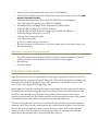
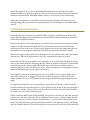
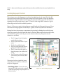
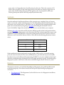
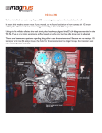
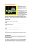
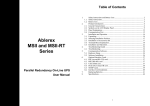
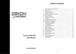
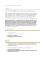
K-Jetronic to Megasquirt II Conversion Introduction In the mid-1970s, Bosch MgbH introduced a fuel injection system called K-Jetronic. It functioned as a constant injection system with fuel to the injectors being controlled by an airflow metering plate and injector opening controlled by fuel pressure instead of an electronic signal. Though there are many variations on the system, the basics operating principles of the system are the same across all variations. Many automotive marques adopted this system, including Porsche, Mercedes-Benz, Ferrari, Volkswagen, Volvo, SAAB, DeLorean, Audi, and BMW, among others. The system was state of the art in its time, but its benefits and performance have been outpaced by modern electronic fuel injection (EFI) systems. K-Jetronic systems have become difficult to source parts for and expensive to maintain, and all but the most specialized mechanics no longer understand the basic principles of operation, making maintenance difficult. A popular alternative to K-Jetronic is the conversion to a modern fuel injection system. A common choice is the Megasquirt II Engine Management System (EMS) which not only controls fuel injection, but is also capable of controlling ignition and many other facets of vehicle operation. This guide will discuss the conversion of a 1979 Volvo 244 from its original K-Jetronic fuel injection and pointsless ignition to EFI and electronic, coilnear-plug ignition using Megasquirt. Features and Benefits • • • • • • Increased performance Ability to tune the EMS from a laptop computer Increased efficiency Improved ease of maintenance Affordable and cost effective ($300-$600) Increased reliability Materials List Required Items • • • • • Megasquirt ECU-available as a kit assembled by the user, or a fully assembled ECU. (This guide discusses the preassembled MSII v3.57 ECU. Some procedures and wiring may differ by application.) Wiring Harness (available from RS-Autosport.com or DIYAutotune.com) Late-model (1983-1996) Volvo B230F intake manifold and fuel rail Custom fuel supply and return lines Suitable fuel injectors (many electronic fuel injectors are dimensionally similar. Choose injectors based on fuel flow rate) • • • • • • • • • • • • • Volvo LH 2.4 coolant temperature sensor (Volvo P/N 8788200) Volvo LH 3.1 throttle body and throttle position sensor (from 1991-93 Volvo 240 with manual transmission only) GM Intake Air Temperature sensor (GM P/N 25036751) and wiring pigtail Four GMC/Chevrolet ignition coils (GM P/N 12558693) Mitsubishi/DSM Crank Angle Sensor (Mitsubishi P/N MD121786) Yoshifab DSM CAS Adapter (Yoshifab P/N BIL52) Yoshifab DSM CAS High-Resolution trigger disc (Yoshifab P/N HIGW2) Wideband Oxygen Sensor (Innovate LC-1) 3 30 amp 4-pin automotive relays 5-fuse blade fuse holder Spare 12-20 AWG wire in various colors Electrical Connectors (fuel injectors, coil packs, engine sensors, butt splice crimps, etc.) Heat-shrink tubing Optional Items-Installation of these items not described. • • • Volvo 530 Cylinder Head to replace the 398 or 460 K-Jetronic cylinder head. The 530 cylinder head does not need the K-Jetronic fuel injector holes plugged. Idle Air Motor Fast Idle Solenoid Removing the K-Jetronic System Begin the removal of the K-Jet system inside the passenger compartment. The K-Jetronic ECU is located under the passenger kick panel. Remove the ECU and the wiring harness. Simply pull the harness back from the passenger side to under the driver’s side dashboard, and cut the wires. None of the original ECU wiring will be used. In the engine bay, begin by removing the original intake manifold, then remove the K-Jetronic fuel distributor and air metering plate from its mounting. Remove the fuel feed line from the fuel filter on the firewall, above the brake booster. Remove the fuel return line from its connection near the fuel feed line. Remove the four injectors from their mounts in the cylinder head and then remove the entire K-Jetronic fuel unit from the engine bay. There are several electrical connectors associated with the K-Jetronic system that need to be removed as well. These include connections for the Control Pressure Regulator, the Cold Start Injector, the factory temperature sensor, and the Frequency Valve. Each of these electrical connector’s wires can be traced back to the large gray connector mounted on the firewall behind the intake manifold and be removed from that connector. Rotate the engine to TDC, remove the distributor hold-down bolt, and then remove the ignition distributor by pulling straight up. Take out all associated wiring. Remove the ignition module mounted near the windshield washer reservoir, and remove all associated wiring. Unbolt the stock ignition coil and ballast resistor from the passenger side strut tower. Cut existing wiring and tuck it back in the wire sheathing. Discard the ignition coil and the ballast resistor. Installing Megasquirt-Mechanical Back under the hood, it is time to install the DSM CAS adapter. With the motor still at TDC, simply slide the adapter into the hole that previously held the ignition distributor, and bolt it down with the supplied hardware. Next, decide where to mount the ignition coil packs. A valve cover mount is a popular and easy solution. A simple bracket made from 5/8”x1” aluminum bar stock can be fabricated and welded to the stock valve cover. This places the ignition coils away from components that are susceptible to electromagnetic interference and makes wiring and maintenance simple. Remove the original temperature sensor from the rear of the cylinder head, under the number 4 intake port. Thread the replacement Volvo LH 2.4 temperature sensor in its place. Mount the GM IAT sensor in ambient air, preferably on one of the empty threaded mounting holes on the intake manifold. Mounting the IAT sensor in ambient air instead of in the intake tract both negates the need to weld a threaded bung onto the intake manifold, and on a turbocharged car, provides the ECU with a more accurate temperature reading which results in improved ambient temperature fueling compensation. The original K-Jetronic mechanical fuel injectors were held in recesses in the cylinder head itself which will need to be plugged. The new electronic fuel injectors will be placed in the intake manifold. If a Volvo 530 cylinder head is being used, the following paragraph does not apply. To plug the existing holes, one of two methods is generally used. The first, which is also the stronger and more professional option, is to TIG weld the holes closed. In the event that this is not practical, another solution is to use a nickel placed in the hole, and held in with JB-Weld® or a similar two-part steel-reinforced epoxy. Finally, install the B230F style intake manifold, fuel injectors, and fuel rail. Since the fuel feed connection on the later style fuel rail is in a different location and is a different style than the fuel feed connection on the K-Jetronic fuel distributor, a custom fuel feed line will need to be made. Any shop that makes custom hydraulic lines will have the appropriate hose and fittings, and can assemble the hose. The fuel return line sees lower pressure, and can be fabricated with 5/16” or 6mm inside diameter nylon fuel injection line available from the same hydraulic hose shop. Installing Megasquirt-Electrical The wiring necessary for Megasquirt is relatively straightforward and simple. Both the RSAutosport harness and the DIY Autotune harness have labels printed on each wire detailing their function. Begin installation by following the instructions that came with the harness regarding the short ground wires on pins 7-11 and 19 of the large DB37 connector. A good electrical ground is crucial for reliable operation. Figure 1.1 illustrates a typical wiring diagram supplied with each Megasquirt harness. Please note that the wiring diagram is meant only as a guide, and will vary with each installation. Moving back into the passenger compartment, begin wiring by finding the stock fuel pump relay (large green 6-pin relay) under the driver’s side dash. Remove the relay from the socket, and observe the numbers near the pins on the bottom of the relay. The pinout for the connector is as follows: • • • • • • Pin 15: trigger from the ignition switch (blue/red wire) Pin 30: power from fuse #7 (red wire) Pin 31: Ground (black wire) Pin 37b: power from the factory ignition coil (white/red wire) Pin 87: Power from the relay to the fuel pumps. (two yellow/red wires) Pin 87b: power to the K-Jetronic system relay on the fender (blue wire) These wires for the original fuel pump relay will interface with two of the new relays for Megasquirt. Fuel Pump Power: Connect the wire from pin 87 of the stock relay to pin 87 of the new fuel pump relay and pin 87 of the main relay. Figure 1.1: Basic Wiring Diagram Relay Trigger Voltage: The blue and red wire from pin 15 of the old relay will provide the voltage necessary to trigger both the new fuel pump relay and main relay to turn on. Connect this wire to pin 86 of both new relays. Constant +12V Supply: On the old relay, power is supplied by the red wire on pin 30. Connect this wire to pin 30 of both new relays. This will be the constant +12V power switched on by the ignition key trigger voltage. Fuel Pump ECU Trigger: Find the blue wire labeled FUEL PUMP on pin 37 of the DB37. Connect this wire to pin 85 of the new fuel pump relay. The ECU will ground this pin to turn the pumps on. Main Relay Ground: Ground pin 85 of the Main Relay to a clean ground point on the chassis, ideally the same location where pins 7-11 and 19 from the DB37 ground to the chassis. Fuse Block Power Feed: Connect pin 87 from the main relay to the new 5-position fuse block. This will provide power to all the new fuses which will power the DSM CAS, the fuel injectors, and the Megasquirt ECU. Route the needed wires from the DB37 through the firewall. Leads from the DB37 should be routed around the engine bay and sheathed for protection. Sensor wiring is described in the following list. Refer to figure 1.2 for TPS wiring pinout. A tutorial on setting up the DSM CAS with the high-resolution trigger disc can be found in the articles section on the Turbobricks forum. It is advised that all sensors are connected through removable electrical connectors such as GM-style “Weatherpack” connectors to simplify sensor removal for maintenance or replacement at a later date. Sensor Wiring • • • Volvo Coolant Temperature Sensor: Grounds through the sensor body threads. Connect the CLT SIG wire from the DB37 to either pin on the sensor. GM IAT: One lead from the two-pin plug must be grounded. The other pin is connected to the MAT SIG wire from the DB37. Volvo TPS: Ground Pin 1 to the intake manifold. Pin 2 is connected to TPS VREF from the DB37. Pin 3 is connected to TPS SIG from the DB37. Figure 1.2: TPS Pinout • DSM CAS: Connect a 2V fused power wire from the fuse block to the red wire on the CAS. The yellow wire provides a crank signal to the ECU on the TACH SIG wire. The black wire should be grounded to the intake manifold. Fuel Injector Wiring Wiring the fuel injectors is straightforward as well. Though the injectors can be wired any one of several ways, this guide will cover grouping the injectors for cylinders 1 and 4 and 2 and 3. This semi-sequential setup will enable better fine-tuning of the injection system than a batchfire system. Power to the fuel injectors is supplied from the new fuse block, with one power lead for each group of injectors. Pins 32 and 33 from the DB37 are grouped together and connected to the unoccupied pins on injectors 1 and 4. Pins 34 and 35 from the DB37 are grouped as well, and connected to the unoccupied pins on injectors 2 and 3. Though fuel injectors are not polarity sensitive, it is recommended that the injectors be wired uniformly, and the wiring color coded to simplify future maintenance and troubleshooting. Ignition Coil Wiring A simple harness should also be built for the ignition coil packs. The ignition coils are also grouped on cylinders 1 and 4 and 2 and 3. Ignition Coil Harness: Pin 1 of the connector on the ignition coil is the ground for the coil, pin 2 is constant +12V power, and pin 3 is a +5V trigger from the ECU. The trigger wires for coils 1 and 4 and 2 and 3 should be grouped and attached to the spark outputs from the Megasquirt ECU. ECU Connection: On the main board on the ECU, locate PAD1 (Spark Output A) and PAD3 (Spark Output B). Figure 1.3 illustrates the location of PAD1 and PAD3 on the main board. Connect these pads with a small jumper wire to two pins of your choosing on the DB15 socket. Assemble the DB15 connector two leads connected to the pins that correspond with where PAD1 and PAD3 are soldered on the DB15 socket. Wiring the Coil Power Relay: Since ignition coils are a high current draw item, it is recommended that power for the coils be supplied through a dedicated relay. For this relay, power should be supplied from the power distribution block on the driver’s side fender. Run a single 10 gauge wire from an empty terminal on the power distribution block to pin 30 of the coil Figure 1.3: Megasquirt v3.57 Main Board power relay. A 15 amp inline fuse should be placed on this wire. This is the constant +12V feed for the coil packs. Use the same trigger wire for the other two relays to trigger the coil power relay. Pin 87 will provide power to the ignition coils. Ground pin 85 to the same chassis ground point used for the fuel pump relay and main relay. Conclusion Once the mechanical and electrical phases of the conversion are completed, the car’s battery can be reconnected, and the vehicle powered on. The ECU will be preloaded with firmware, but will require a tune in the form of a .MSQ file to run. A .MSQ file for the setup described in this guide can be downloaded by navigating to this link and finding the link titled “2012-0104_21.43.08.MSQ”. Right click on that link, and choose to save the link to your computer. Following this video tutorial from DIY Autotune will help greatly in final configuration before starting the vehicle on Megasquirt for the first time. Since the coolant temperature sensor used is different from the GM style that comes preset in Megasquirt, the sensor resistor values are different as well. Set the Bias Resistor Value to 2500 and use the following thermistor resistor values: Temperature (Fahrenheit) Resistance Value (Ω) 32 5300 71 2200 183 230 If the installation has been performed correctly and the .MSQ used is a reasonable starting point, the motor should start. The motor will likely have a poor idle and may not be drivable, but these issues can be addressed through tuning the EMS. If a no-start condition exists, begin with basic troubleshooting, checking first for fuel supply and then for spark. Troubleshooting a Megasquirt system is often much easier than troubleshooting the Bosch K-Jetronic system. Resources The internet contains a vast wealth of knowledge on Megasquirt, along with installation and troubleshooting help. The websites listed below will prove helpful during any Megasquirt conversion. • The Megamanual: The Megamanual is the official resource for Megasquirt installation, help, and troubleshooting. • MS Extra Manuals: MS Extra is much more frequently updated than the Megamanual, and is directed towards a user who has read and understood the basics presented in the Megamanual. Though its documentation is much more technical in nature, it can be much more helpful than the companion Megamanual. • MSefi.com: An internet forum dedicated to the implementation, tuning, and continued use of Megasquirt, MSefi.com is a thriving source of information. Many users find that the personal experience and direct conversation with other users help greatly in the problem solving process. • DIY Autotune: The most popular supplier of Megasquirt ECUs, ECU kits, and accessories. The company offers outstanding technical support and is willing to assist customers in determining and meeting their needs. • Turbobricks Forums: Turbobricks is an online community dedicated to rear wheel drive Volvo performance. Though the site’s main focus is on Volvo performance, there are many users who are extremely experienced with the Megasquirt system and are willing to help find solutions to user’s problems. In addition, the project that inspired this guide may be viewed in the Projects & Restorations subforum. Image Citations: Figure 1.1: RS Autosport Universal Wiring Diagram. Supplied with RS Autosport 12’ Megasquirt wiring harness Figure 1.2: Bentley Publishing Company, Volvo 240 Service Manual. Page 241-20. Figure 1.3: www.Megamanual.com. Megasquirt v3.57 Main Board overview.