1
HP ProCurve Switch Software
Management and Configuration Guide
3500 switches
3500yl switches
5400zl switches
6200yl switches
6600 switches
8200zl switches
Software version K.14.34
September 2009
HP ProCurve
3500 Switches
3500yl Switches
5400zl Switches
6200yl Switch
6600 Switches
8200zl Switches
September 2009
K.14.34
Management and Configuration
Guide
© Copyright 2005–2009 Hewlett-Packard Development Company,
L.P. The information contained herein is subject to change with
out notice. All Rights Reserved.
Disclaimer
This document contains proprietary information, which is
protected by copyright. No part of this document may be
photocopied, reproduced, or translated into another
language without the prior written consent of HewlettPackard.
HEWLETT-PACKARD COMPANY MAKES NO WARRANTY
OF ANY KIND WITH REGARD TO THIS MATERIAL,
INCLUDING, BUT NOT LIMITED TO, THE IMPLIED
WARRANTIES OF MERCHANTABILITY AND FITNESS
FOR A PARTICULAR PURPOSE. Hewlett-Packard shall not
be liable for errors contained herein or for incidental or
consequential damages in connection with the furnishing,
performance, or use of this material.
Publication Number
5992-3059
September 2009
Applicable Products
HP ProCurve Switch 3500-24
HP ProCurve Switch 3500-48
HP ProCurve Switch 3500-24-PoE
HP ProCurve Switch 3500-48-PoE
HP ProCurve Switch 3500yl-24G-PWR
HP ProCurve Switch 3500yl-48G-PWR
HP ProCurve Switch 5406zl
HP ProCurve Switch 5406zl-48G-PoE+
HP ProCurve Switch 5412zl
HP ProCurve Switch 5412zl-96G-PoE+
HP ProCurve Switch 6200yl-24G
HP ProCurve Switch 8206zl
HP ProCurve Switch 8212zl
HP ProCurve Switch 6600-24G
HP ProCurve Switch 6600-24G-4XG
HP ProCurve Switch 6600-24G-24XG
HP ProCurve Switch 6600-48G
HP ProCurve Switch 6600-48G-4XG
(J9470A)
(J9472A)
(J9471A)
(J9473A)
(J8692A)
(J8693A)
(J8697A)
(J9447A)
(J8698A)
(J9448A)
(J8992A)
(J9475A)
(J8715A/B)
(J9263A)
(J9264A)
(J9265A)
(J9451A)
(J9452A)
HP ProCurve 24-Port 10/100/1000 PoE+ zl Module
HP ProCurve 20-Port 10/100/1000 PoE+/4-Port
MiniGBIC zl Module
HP ProCurve 4-Port 10GbE SFP+ zl Module
HP ProCurve 24-Port 10/100 PoE+ zl Module
(J9307A)
(J9308A)
(J9309A)
(J9478A)
Trademark Credits
Microsoft, Windows, and Microsoft Windows NT are US
registered trademarks of Microsoft Corporation. Java™ is a
US trademark of Sun Microsystems, Inc.
Hewlett-Packard Company
8000 Foothills Boulevard, m/s 5551
Roseville, California 95747-5551
http://www.procurve.com
The information contained in this document is subject to
change without notice.
The only warranties for HP products and services are set
forth in the express warranty statements accompanying
such products and services. Nothing herein should be
construed as constituting an additional warranty. HP shall
not be liable for technical or editorial errors or omissions
contained herein.
Hewlett-Packard assumes no responsibility for the use or
reliability of its software on equipment that is not furnished
by Hewlett-Packard.
Warranty
See the Customer Support/Warranty booklet included with
the product.
A copy of the specific warranty terms applicable to your
Hewlett-Packard products and replacement parts can be
obtained from your HP Sales and Service Office or
authorized dealer.
Contents
Product Documentation
About Your Switch Manual Set . . . . . . . . . . . . . . . . . . . . . . . . . . . . xxv
Printed Publications. . . . . . . . . . . . . . . . . . . . . . . . . . . . . . . . . . . . . . . . . xxv
Electronic Publications . . . . . . . . . . . . . . . . . . . . . . . . . . . . . . . . . . . . . . xxv
Software Feature Index . . . . . . . . . . . . . . . . . . . . . . . . . . . . . . . . . xxvi
1 Getting Started
Contents . . . . . . . . . . . . . . . . . . . . . . . . . . . . . . . . . . . . . . . . . . . . . . . . . . . . . . 1-1
Introduction . . . . . . . . . . . . . . . . . . . . . . . . . . . . . . . . . . . . . . . . . . . . . . . . . . 1-2
Conventions . . . . . . . . . . . . . . . . . . . . . . . . . . . . . . . . . . . . . . . . . . . . . . . . . . 1-2
Command Syntax Statements . . . . . . . . . . . . . . . . . . . . . . . . . . . . . . . . . 1-2
Command Prompts . . . . . . . . . . . . . . . . . . . . . . . . . . . . . . . . . . . . . . . . . . 1-3
Screen Simulations . . . . . . . . . . . . . . . . . . . . . . . . . . . . . . . . . . . . . . . . . . 1-3
Configuration and Operation Examples . . . . . . . . . . . . . . . . . . . . . . . . . 1-3
Keys . . . . . . . . . . . . . . . . . . . . . . . . . . . . . . . . . . . . . . . . . . . . . . . . . . . . . . . 1-3
Sources for More Information . . . . . . . . . . . . . . . . . . . . . . . . . . . . . . . . . 1-4
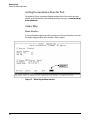
Getting Documentation From the Web . . . . . . . . . . . . . . . . . . . . . . . . . 1-6
Online Help . . . . . . . . . . . . . . . . . . . . . . . . . . . . . . . . . . . . . . . . . . . . . . . . 1-6
Menu Interface . . . . . . . . . . . . . . . . . . . . . . . . . . . . . . . . . . . . . . . . . . 1-6
Command Line Interface . . . . . . . . . . . . . . . . . . . . . . . . . . . . . . . . . . 1-7
Web Browser Interface . . . . . . . . . . . . . . . . . . . . . . . . . . . . . . . . . . . 1-7
Need Only a Quick Start? . . . . . . . . . . . . . . . . . . . . . . . . . . . . . . . . . . . . . . 1-8
IP Addressing . . . . . . . . . . . . . . . . . . . . . . . . . . . . . . . . . . . . . . . . . . . . . . . 1-8
To Set Up and Install the Switch in Your Network . . . . . . . . . . . . . . . 1-8
Physical Installation . . . . . . . . . . . . . . . . . . . . . . . . . . . . . . . . . . . . . . . . . 1-8
i
2 Selecting a Management Interface
Contents . . . . . . . . . . . . . . . . . . . . . . . . . . . . . . . . . . . . . . . . . . . . . . . . . . . . . . 2-1
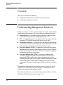
Overview . . . . . . . . . . . . . . . . . . . . . . . . . . . . . . . . . . . . . . . . . . . . . . . . . . . . . 2-2
Understanding Management Interfaces . . . . . . . . . . . . . . . . . . . . . . . . . 2-2
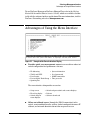
Advantages of Using the Menu Interface . . . . . . . . . . . . . . . . . . . . . . . . 2-3
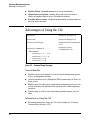
Advantages of Using the CLI . . . . . . . . . . . . . . . . . . . . . . . . . . . . . . . . . . . 2-4
General Benefits . . . . . . . . . . . . . . . . . . . . . . . . . . . . . . . . . . . . . . . . . 2-4
Information on Using the CLI . . . . . . . . . . . . . . . . . . . . . . . . . . . . . . 2-4
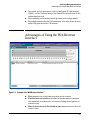
Advantages of Using the Web Browser Interface . . . . . . . . . . . . . . . . 2-5
Advantages of Using ProCurve Manager
or ProCurve Manager Plus . . . . . . . . . . . . . . . . . . . . . . . . . . . . . . . . . . . . . 2-7
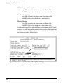
Custom Login Banners for the Console and
Web Browser Interfaces . . . . . . . . . . . . . . . . . . . . . . . . . . . . . . . . . . . . . . 2-9
Banner Operation with Telnet, Serial, or SSHv2 Access . . . . . . . . 2-9
Banner Operation with Web Browser Access . . . . . . . . . . . . . . . . 2-9
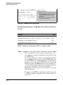
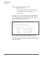
Configuring and Displaying a Non-Default Banner . . . . . . . . . . . 2-10
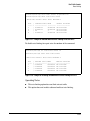
Example of Configuring and Displaying a Banner . . . . . . . . . . . . 2-11
Operating Notes . . . . . . . . . . . . . . . . . . . . . . . . . . . . . . . . . . . . . . . . 2-13
3 Using the Menu Interface
Contents . . . . . . . . . . . . . . . . . . . . . . . . . . . . . . . . . . . . . . . . . . . . . . . . . . . . . . 3-1
Overview . . . . . . . . . . . . . . . . . . . . . . . . . . . . . . . . . . . . . . . . . . . . . . . . . . . . . 3-2
Starting and Ending a Menu Session . . . . . . . . . . . . . . . . . . . . . . . . . . . 3-3
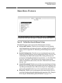
How To Start a Menu Interface Session . . . . . . . . . . . . . . . . . . . . . . . . . 3-4
How To End a Menu Session and Exit from the Console: . . . . . . . . . . 3-5
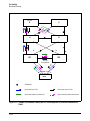
Main Menu Features . . . . . . . . . . . . . . . . . . . . . . . . . . . . . . . . . . . . . . . . . . 3-7
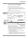
Screen Structure and Navigation . . . . . . . . . . . . . . . . . . . . . . . . . . . . . . . 3-9
Rebooting the Switch . . . . . . . . . . . . . . . . . . . . . . . . . . . . . . . . . . . . . . . . . 3-12
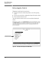
Menu Features List . . . . . . . . . . . . . . . . . . . . . . . . . . . . . . . . . . . . . . . . . . . 3-14
Where To Go From Here . . . . . . . . . . . . . . . . . . . . . . . . . . . . . . . . . . . . . . 3-15
ii
4 Using the Command Line Interface (CLI)
Contents . . . . . . . . . . . . . . . . . . . . . . . . . . . . . . . . . . . . . . . . . . . . . . . . . . . . . . 4-1
Overview . . . . . . . . . . . . . . . . . . . . . . . . . . . . . . . . . . . . . . . . . . . . . . . . . . . . . 4-2
Accessing the CLI . . . . . . . . . . . . . . . . . . . . . . . . . . . . . . . . . . . . . . . . . . . . . 4-2
Using the CLI . . . . . . . . . . . . . . . . . . . . . . . . . . . . . . . . . . . . . . . . . . . . . . . . . 4-2
Privilege Levels at Logon . . . . . . . . . . . . . . . . . . . . . . . . . . . . . . . . . . . . . 4-3
Privilege Level Operation . . . . . . . . . . . . . . . . . . . . . . . . . . . . . . . . . . . . . 4-4
Operator Privileges . . . . . . . . . . . . . . . . . . . . . . . . . . . . . . . . . . . . . . 4-4
Manager Privileges . . . . . . . . . . . . . . . . . . . . . . . . . . . . . . . . . . . . . . . 4-5
How To Move Between Levels . . . . . . . . . . . . . . . . . . . . . . . . . . . . . . . . 4-7
Listing Commands and Command Options . . . . . . . . . . . . . . . . . . . . . . 4-8
Listing Commands Available at Any Privilege Level . . . . . . . . . . . 4-8
Listing Command Options . . . . . . . . . . . . . . . . . . . . . . . . . . . . . . . 4-10
Displaying CLI “Help” . . . . . . . . . . . . . . . . . . . . . . . . . . . . . . . . . . . . . . . 4-11
Configuration Commands and the Context Configuration Modes . . 4-13
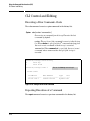
CLI Control and Editing . . . . . . . . . . . . . . . . . . . . . . . . . . . . . . . . . . . . . . 4-16
Executing a Prior Command—Redo . . . . . . . . . . . . . . . . . . . . . . . . . . 4-16
Repeating Execution of a Command . . . . . . . . . . . . . . . . . . . . . . . . . . 4-16
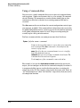
Using a Command Alias . . . . . . . . . . . . . . . . . . . . . . . . . . . . . . . . . . . . . 4-18
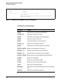
CLI Shortcut Keystrokes . . . . . . . . . . . . . . . . . . . . . . . . . . . . . . . . . . . . 4-20
5 Using the ProCurve Web Browser Interface
Contents . . . . . . . . . . . . . . . . . . . . . . . . . . . . . . . . . . . . . . . . . . . . . . . . . . . . . . 5-1
Overview . . . . . . . . . . . . . . . . . . . . . . . . . . . . . . . . . . . . . . . . . . . . . . . . . . . . . 5-3
General Features . . . . . . . . . . . . . . . . . . . . . . . . . . . . . . . . . . . . . . . . . . . . . . 5-4
Starting a Web Browser
Interface Session with the Switch . . . . . . . . . . . . . . . . . . . . . . . . . . . . . . 5-5
Using a Standalone Web Browser in a PC or UNIX Workstation . . . . 5-5
Using ProCurve Manager (PCM) or ProCurve Manager Plus (PCM+) . . . . . . . . . . . . . . . . . . . . . . . . . . . . . . . 5-6
Tasks for Your First ProCurve Web Browser Interface Session . . 5-8
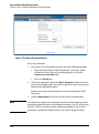
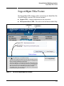
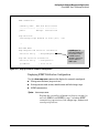
Viewing the “First Time Install” Window . . . . . . . . . . . . . . . . . . . . . . . . 5-8
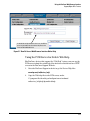
Security: Creating Usernames and Passwords
in the Browser Interface . . . . . . . . . . . . . . . . . . . . . . . . . . . . . . . . . . . . . . 5-9
iii
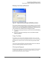
Entering a User Name and Password . . . . . . . . . . . . . . . . . . . . . . 5-11
Using a User Name . . . . . . . . . . . . . . . . . . . . . . . . . . . . . . . . . . . . . . 5-11
If You Lose the Password . . . . . . . . . . . . . . . . . . . . . . . . . . . . . . . . 5-11
Online Help for the Web Browser Interface . . . . . . . . . . . . . . . . . . . . 5-12
Support/Mgmt URLs Feature . . . . . . . . . . . . . . . . . . . . . . . . . . . . . . . . . . 5-13
Support URL . . . . . . . . . . . . . . . . . . . . . . . . . . . . . . . . . . . . . . . . . . . . . . 5-14
Help and the Management Server URL . . . . . . . . . . . . . . . . . . . . . . . . 5-14
Using the PCM Server for Switch Web Help . . . . . . . . . . . . . . . . . . . . 5-15
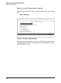
Status Reporting Features . . . . . . . . . . . . . . . . . . . . . . . . . . . . . . . . . . . . 5-17
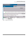
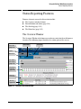
The Overview Window . . . . . . . . . . . . . . . . . . . . . . . . . . . . . . . . . . . . . . 5-17
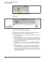
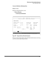
The Port Utilization and Status Displays . . . . . . . . . . . . . . . . . . . . . . . 5-18
Port Utilization . . . . . . . . . . . . . . . . . . . . . . . . . . . . . . . . . . . . . . . . . 5-18
Port Status . . . . . . . . . . . . . . . . . . . . . . . . . . . . . . . . . . . . . . . . . . . . . 5-20
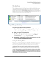
The Alert Log . . . . . . . . . . . . . . . . . . . . . . . . . . . . . . . . . . . . . . . . . . . . . . 5-21
Sorting the Alert Log Entries . . . . . . . . . . . . . . . . . . . . . . . . . . . . . 5-21
Alert Types and Detailed Views . . . . . . . . . . . . . . . . . . . . . . . . . . . 5-22
Status Indicators . . . . . . . . . . . . . . . . . . . . . . . . . . . . . . . . . . . . . . . 5-23
Setting Fault Detection Policy . . . . . . . . . . . . . . . . . . . . . . . . . . . . . . . . 5-24
6
Switch Memory and Configuration
Contents . . . . . . . . . . . . . . . . . . . . . . . . . . . . . . . . . . . . . . . . . . . . . . . . . . . . . . 6-1
Overview . . . . . . . . . . . . . . . . . . . . . . . . . . . . . . . . . . . . . . . . . . . . . . . . . . . . . 6-3
Configuration File Management . . . . . . . . . . . . . . . . . . . . . . . . . . . . . . . . 6-3
Using the CLI To Implement Configuration Changes . . . . . . . . . . . . 6-6
Using the Menu and Web Browser Interfaces To Implement Configuration Changes . . . . . . . . . . . . . . . . . . . . . . . . . . . . . . . . . . . . . . . 6-10
Menu: Implementing Configuration Changes . . . . . . . . . . . . . . . . . . . 6-10
Using Save and Cancel in the Menu Interface . . . . . . . . . . . . . . . 6-10
Rebooting from the Menu Interface . . . . . . . . . . . . . . . . . . . . . . . 6-11
Web: Implementing Configuration Changes . . . . . . . . . . . . . . . . . . . . 6-13
Using Primary and Secondary Flash Image Options . . . . . . . . . . . . . 6-14
Displaying the Current Flash Image Data . . . . . . . . . . . . . . . . . . . . . . 6-14
Switch Software Downloads . . . . . . . . . . . . . . . . . . . . . . . . . . . . . . . . . 6-16
Local Switch Software Replacement and Removal . . . . . . . . . . . . . . 6-17
iv
Rebooting the Switch . . . . . . . . . . . . . . . . . . . . . . . . . . . . . . . . . . . . . . . 6-19
Operating Notes about Booting . . . . . . . . . . . . . . . . . . . . . . . . . . . 6-19
Boot and Reload Command Comparison . . . . . . . . . . . . . . . . . . . 6-20
Setting the Default Flash . . . . . . . . . . . . . . . . . . . . . . . . . . . . . . . . . 6-21
Booting from the Default Flash (Primary or Secondary) . . . . . . 6-22
Booting from a Specified Flash . . . . . . . . . . . . . . . . . . . . . . . . . . . 6-23
Using Reload . . . . . . . . . . . . . . . . . . . . . . . . . . . . . . . . . . . . . . . . . . . 6-24
Multiple Configuration Files . . . . . . . . . . . . . . . . . . . . . . . . . . . . . . . . . . 6-26
General Operation . . . . . . . . . . . . . . . . . . . . . . . . . . . . . . . . . . . . . . . . . . 6-27
Transitioning to Multiple Configuration Files . . . . . . . . . . . . . . . . . . . 6-29
Listing and Displaying Startup-Config Files . . . . . . . . . . . . . . . . . . . . . 6-30
Viewing the Startup-Config File Status with Multiple
Configuration Enabled . . . . . . . . . . . . . . . . . . . . . . . . . . . . . . . . . . 6-30
Displaying the Content of A Specific Startup-Config File . . . . . . 6-31
Changing or Overriding the Reboot Configuration Policy . . . . . . . . . 6-31
Managing Startup-Config Files in the Switch . . . . . . . . . . . . . . . . . . . 6-33
Renaming an Existing Startup-Config File . . . . . . . . . . . . . . . . . . 6-34
Creating a New Startup-Config File . . . . . . . . . . . . . . . . . . . . . . . . 6-34
Erasing a Startup-Config File . . . . . . . . . . . . . . . . . . . . . . . . . . . . . 6-35
Using the Clear + Reset Button Combination To Reset the
Switch to Its Default Configuration . . . . . . . . . . . . . . . . . . . . . . . . 6-37
Transferring Startup-Config Files To or From a Remote Server . . . . 6-38
TFTP: Copying a Configuration File to a Remote Host . . . . . . . . 6-38
TFTP: Copying a Configuration File from a Remote Host . . . . . 6-39
Xmodem: Copying a Configuration File to a Serially
Connected Host . . . . . . . . . . . . . . . . . . . . . . . . . . . . . . . . . . . . . . . . 6-40
Xmodem: Copying a Configuration from a Serially
Connected Host . . . . . . . . . . . . . . . . . . . . . . . . . . . . . . . . . . . . . . . . 6-40
Operating Notes for Multiple Configuration Files . . . . . . . . . . . . 6-40
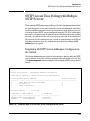
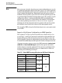
Automatic Configuration Update with DHCP Option 66 . . . . . . . . 6-41
CLI Command . . . . . . . . . . . . . . . . . . . . . . . . . . . . . . . . . . . . . . . . . . . . . 6-41
Possible Scenarios for Updating the Configuration File . . . . . . . . . . 6-42
Operating Notes . . . . . . . . . . . . . . . . . . . . . . . . . . . . . . . . . . . . . . . . . . . . 6-42
Log Messages . . . . . . . . . . . . . . . . . . . . . . . . . . . . . . . . . . . . . . . . . . . . . . 6-43
v
7 Interface Access and System Information
Contents . . . . . . . . . . . . . . . . . . . . . . . . . . . . . . . . . . . . . . . . . . . . . . . . . . . . . . 7-1
Overview . . . . . . . . . . . . . . . . . . . . . . . . . . . . . . . . . . . . . . . . . . . . . . . . . . . . . 7-2
Interface Access: Console/Serial Link, Web, and Inbound Telnet . 7-3
Menu: Modifying the Interface Access . . . . . . . . . . . . . . . . . . . . . . . . . . 7-4
CLI: Modifying the Interface Access . . . . . . . . . . . . . . . . . . . . . . . . . . . . 7-5
Denying Interface Access by Terminating Remote Management Sessions . . . . . . . . . . . . . . . . . . . . . . . . . . . . . . . . . . . . . . . . . . . . . . . . . . . . . 7-11
System Information . . . . . . . . . . . . . . . . . . . . . . . . . . . . . . . . . . . . . . . . . . 7-12
Menu: Viewing and Configuring System Information . . . . . . . . . . . . . 7-13
CLI: Viewing and Configuring System Information . . . . . . . . . . . . . . 7-14
Web: Configuring System Parameters . . . . . . . . . . . . . . . . . . . . . . . . . 7-18
8 Configuring IP Addressing
Contents . . . . . . . . . . . . . . . . . . . . . . . . . . . . . . . . . . . . . . . . . . . . . . . . . . . . . . 8-1
Overview . . . . . . . . . . . . . . . . . . . . . . . . . . . . . . . . . . . . . . . . . . . . . . . . . . . . . 8-2
IP Configuration . . . . . . . . . . . . . . . . . . . . . . . . . . . . . . . . . . . . . . . . . . . . . . 8-2
Just Want a Quick Start with IP Addressing? . . . . . . . . . . . . . . . . . . . . 8-4
IP Addressing with Multiple VLANs . . . . . . . . . . . . . . . . . . . . . . . . . . . . 8-4
Menu: Configuring IP Address, Gateway, and Time-To-Live (TTL) . . 8-5
CLI: Configuring IP Address, Gateway, and Time-To-Live (TTL) . . . . 8-7
Web: Configuring IP Addressing . . . . . . . . . . . . . . . . . . . . . . . . . . . . . . 8-11
How IP Addressing Affects Switch Operation . . . . . . . . . . . . . . . . . . . 8-11
DHCP/Bootp Operation . . . . . . . . . . . . . . . . . . . . . . . . . . . . . . . . . . 8-12
Network Preparations for Configuring DHCP/Bootp . . . . . . . . . 8-15
Loopback Interfaces . . . . . . . . . . . . . . . . . . . . . . . . . . . . . . . . . . . . . . . . . . 8-16
Introduction . . . . . . . . . . . . . . . . . . . . . . . . . . . . . . . . . . . . . . . . . . . . . . . 8-16
Configuring a Loopback Interface . . . . . . . . . . . . . . . . . . . . . . . . . . . . 8-17
Displaying Loopback Interface Configurations . . . . . . . . . . . . . . . . . . 8-18
IP Preserve: Retaining VLAN-1 IP
Addressing Across Configuration File Downloads . . . . . . . . . . . . . . 8-21
Operating Rules for IP Preserve . . . . . . . . . . . . . . . . . . . . . . . . . . . . . . 8-21
Enabling IP Preserve . . . . . . . . . . . . . . . . . . . . . . . . . . . . . . . . . . . . . . . . 8-22
vi
Configuring a Single Source IP Address . . . . . . . . . . . . . . . . . . . . . . . 8-25
Overview . . . . . . . . . . . . . . . . . . . . . . . . . . . . . . . . . . . . . . . . . . . . . . . . . . 8-25
Specifying the Source IP Address . . . . . . . . . . . . . . . . . . . . . . . . . . . . . 8-25
The Source IP Selection Policy . . . . . . . . . . . . . . . . . . . . . . . . . . . 8-26
Displaying the Source IP Interface Information . . . . . . . . . . . . . . . . . 8-29
Error Messages . . . . . . . . . . . . . . . . . . . . . . . . . . . . . . . . . . . . . . . . . . . . 8-32
9 Time Protocols
Contents . . . . . . . . . . . . . . . . . . . . . . . . . . . . . . . . . . . . . . . . . . . . . . . . . . . . . . 9-1
Overview . . . . . . . . . . . . . . . . . . . . . . . . . . . . . . . . . . . . . . . . . . . . . . . . . . . . . 9-3
TimeP Time Synchronization . . . . . . . . . . . . . . . . . . . . . . . . . . . . . . . . . . 9-3
SNTP Time Synchronization . . . . . . . . . . . . . . . . . . . . . . . . . . . . . . . . . . 9-3
Selecting a Time Synchronization Protocol or Turning Off Time Protocol Operation . . . . . . . . . . . . . . . . . . . . . . . . . . . . . . . . . . . . . . . . . . . . 9-4
General Steps for Running a Time Protocol on the Switch: . . . . . . . . 9-4
Disabling Time Synchronization . . . . . . . . . . . . . . . . . . . . . . . . . . . . . . . 9-5
SNTP: Viewing, Selecting, and Configuring . . . . . . . . . . . . . . . . . . . . . 9-5
Menu: Viewing and Configuring SNTP . . . . . . . . . . . . . . . . . . . . . . . . . . 9-6
CLI: Viewing and Configuring SNTP . . . . . . . . . . . . . . . . . . . . . . . . . . . . 9-9
Viewing the Current SNTP Configuration . . . . . . . . . . . . . . . . . . . . 9-9
Configuring (Enabling or Disabling) the SNTP Mode . . . . . . . . . 9-11
SNTP Client Authentication . . . . . . . . . . . . . . . . . . . . . . . . . . . . . . . . . 9-16
Requirements . . . . . . . . . . . . . . . . . . . . . . . . . . . . . . . . . . . . . . . . . . 9-17
Configuring the Key-Identifier, Authentication Mode, and
Key-Value . . . . . . . . . . . . . . . . . . . . . . . . . . . . . . . . . . . . . . . . . . . . . 9-18
Configuring a Trusted Key . . . . . . . . . . . . . . . . . . . . . . . . . . . . . . . 9-19
Associating a Key with an SNTP Server . . . . . . . . . . . . . . . . . . . . 9-20
Enabling SNTP Client Authentication . . . . . . . . . . . . . . . . . . . . . . 9-20
Configuring Unicast and Broadcast Mode . . . . . . . . . . . . . . . . . . 9-21
Displaying SNTP Configuration Information . . . . . . . . . . . . . . . . 9-21
Saving Configuration Files and the
Include-Credentials Command . . . . . . . . . . . . . . . . . . . . . . . . . . . . 9-23
TimeP: Viewing, Selecting, and Configuring . . . . . . . . . . . . . . . . . . . . 9-26
Menu: Viewing and Configuring TimeP . . . . . . . . . . . . . . . . . . . . . . . . 9-27
CLI: Viewing and Configuring TimeP . . . . . . . . . . . . . . . . . . . . . . . . . . 9-28
vii
Viewing the Current TimeP Configuration . . . . . . . . . . . . . . . . . . 9-29
Configuring (Enabling or Disabling) the TimeP Mode . . . . . . . . 9-30
SNTP Unicast Time Polling with Multiple SNTP Servers . . . . . . . . 9-35
Displaying All SNTP Server Addresses Configured on the Switch . . 9-35
Adding and Deleting SNTP Server Addresses . . . . . . . . . . . . . . . . . . . 9-36
Menu: Operation with Multiple SNTP Server Addresses
Configured . . . . . . . . . . . . . . . . . . . . . . . . . . . . . . . . . . . . . . . . . . . . . . . . 9-36
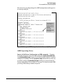
SNTP Messages in the Event Log . . . . . . . . . . . . . . . . . . . . . . . . . . . . . . 9-36
10
Port Status and Configuration
Contents . . . . . . . . . . . . . . . . . . . . . . . . . . . . . . . . . . . . . . . . . . . . . . . . . . . . . 10-1
Overview . . . . . . . . . . . . . . . . . . . . . . . . . . . . . . . . . . . . . . . . . . . . . . . . . . . . 10-3
Viewing Port Status and Configuring Port Parameters . . . . . . . . . . 10-3
Menu: Port Configuration . . . . . . . . . . . . . . . . . . . . . . . . . . . . . . . . . . . . 10-6
CLI: Viewing Port Status and Configuring Port Parameters . . . . . . . 10-8
Viewing Port Status and Configuration . . . . . . . . . . . . . . . . . . . . . 10-8
Customizing the Show Interfaces Command . . . . . . . . . . . . . . . . . . . 10-10
Error Messages . . . . . . . . . . . . . . . . . . . . . . . . . . . . . . . . . . . . . . . . 10-12
Note on Using Pattern Matching with the
“Show Interfaces Custom” Command . . . . . . . . . . . . . . . . . . . . . 10-13
Viewing Port Utilization Statistics . . . . . . . . . . . . . . . . . . . . . . . . . . . 10-13
Viewing Transceiver Status . . . . . . . . . . . . . . . . . . . . . . . . . . . . . . . . . 10-14
Enabling or Disabling Ports and Configuring Port Mode . . . . . . . . . 10-15
Enabling or Disabling the USB Port . . . . . . . . . . . . . . . . . . . . . . . . . . 10-17
Behavior of Autorun When USB Port is Disabled . . . . . . . . . . . 10-18
Enabling or Disabling Flow Control . . . . . . . . . . . . . . . . . . . . . . . . . . 10-18
Configuring a Broadcast Limit on the Switch . . . . . . . . . . . . . . . . . . 10-20
Configuring ProCurve Auto-MDIX . . . . . . . . . . . . . . . . . . . . . . . . . . . 10-21
Web: Viewing Port Status and Configuring Port Parameters . . . . . 10-24
Using Friendly (Optional) Port Names . . . . . . . . . . . . . . . . . . . . . . . 10-25
Configuring and Operating Rules for Friendly Port Names . . . . . . . 10-25
Configuring Friendly Port Names . . . . . . . . . . . . . . . . . . . . . . . . . . . . 10-26
Displaying Friendly Port Names with Other Port Data . . . . . . . . . . 10-27
Configuring Transceivers and Modules That Haven’t
Been Inserted . . . . . . . . . . . . . . . . . . . . . . . . . . . . . . . . . . . . . . . . . . . . . 10-31
viii
Transceivers . . . . . . . . . . . . . . . . . . . . . . . . . . . . . . . . . . . . . . . . . . 10-31
Modules . . . . . . . . . . . . . . . . . . . . . . . . . . . . . . . . . . . . . . . . . . . . . . 10-31
Clearing the Module Configuration . . . . . . . . . . . . . . . . . . . . . . . . . . . 10-31
Operating Notes . . . . . . . . . . . . . . . . . . . . . . . . . . . . . . . . . . . . . . . 10-32
Uni-Directional Link Detection (UDLD) . . . . . . . . . . . . . . . . . . . . . . 10-33
Configuring UDLD . . . . . . . . . . . . . . . . . . . . . . . . . . . . . . . . . . . . . . . . . 10-34
Enabling UDLD . . . . . . . . . . . . . . . . . . . . . . . . . . . . . . . . . . . . . . . . 10-35
Changing the Keepalive Interval . . . . . . . . . . . . . . . . . . . . . . . . . 10-36
Changing the Keepalive Retries . . . . . . . . . . . . . . . . . . . . . . . . . . 10-36
Configuring UDLD for Tagged Ports . . . . . . . . . . . . . . . . . . . . . . 10-36
Viewing UDLD Information . . . . . . . . . . . . . . . . . . . . . . . . . . . . . . . . . 10-37
Configuration Warnings and Event Log Messages . . . . . . . . . . . . . . 10-39
11 Power Over Ethernet (PoE/PoE+) Operation
Contents . . . . . . . . . . . . . . . . . . . . . . . . . . . . . . . . . . . . . . . . . . . . . . . . . . . . . 11-1
Introduction to PoE . . . . . . . . . . . . . . . . . . . . . . . . . . . . . . . . . . . . . . . . . . 11-3
PoE Terminology . . . . . . . . . . . . . . . . . . . . . . . . . . . . . . . . . . . . . . . . . . . 11-3
PoE Operation . . . . . . . . . . . . . . . . . . . . . . . . . . . . . . . . . . . . . . . . . . . . . . . 11-5
Configuration Options . . . . . . . . . . . . . . . . . . . . . . . . . . . . . . . . . . . . . . 11-5
PD Support . . . . . . . . . . . . . . . . . . . . . . . . . . . . . . . . . . . . . . . . . . . . . . . . 11-6
Power Priority Operation . . . . . . . . . . . . . . . . . . . . . . . . . . . . . . . . . . . . 11-7
When Is Power Allocation Prioritized? . . . . . . . . . . . . . . . . . . . . . 11-7
How Is Power Allocation Prioritized? . . . . . . . . . . . . . . . . . . . . . . 11-7
Configuring PoE Operation . . . . . . . . . . . . . . . . . . . . . . . . . . . . . . . . . . . 11-8
Disabling or Re-Enabling PoE Port Operation . . . . . . . . . . . . . . . . . . 11-8
Enabling Support for Pre-Standard Devices . . . . . . . . . . . . . . . . . . . . 11-8
Configuring the PoE Port Priority Level . . . . . . . . . . . . . . . . . . . . . . . 11-9
PoE Priority With Two or More Modules . . . . . . . . . . . . . . . . . . 11-10
Controlling PoE Allocation . . . . . . . . . . . . . . . . . . . . . . . . . . . . . . . . . 11-12
Manually Configuring PoE Power Levels . . . . . . . . . . . . . . . . . . . . . . 11-13
Configuring PoE Redundancy (Chassis Switches Only) . . . . . . . . . 11-14
Changing the Threshold for Generating a Power Notice . . . . . . . . . 11-15
PoE/PoE+ Allocation Using LLDP Information . . . . . . . . . . . . . . . . 11-18
LLDP with PoE . . . . . . . . . . . . . . . . . . . . . . . . . . . . . . . . . . . . . . . . . . . 11-18
ix
Displaying the Switch’s Global PoE Power Status . . . . . . . . . . . . . 11-19
Displaying PoE Status on All Ports . . . . . . . . . . . . . . . . . . . . . . . . . . . 11-21
Displaying the PoE Status on Specific Ports . . . . . . . . . . . . . . . . . . . 11-23
Planning and Implementing a PoE Configuration . . . . . . . . . . . . . . 11-25
Power Requirements . . . . . . . . . . . . . . . . . . . . . . . . . . . . . . . . . . . . . . . 11-25
Assigning PoE Ports to VLANs . . . . . . . . . . . . . . . . . . . . . . . . . . . . . . 11-26
Applying Security Features to PoE Configurations . . . . . . . . . . . . . 11-26
Assigning Priority Policies to PoE Traffic . . . . . . . . . . . . . . . . . . . . . 11-26
PoE Event Log Messages . . . . . . . . . . . . . . . . . . . . . . . . . . . . . . . . . . . . 11-28
“Informational” PoE Event-Log Messages . . . . . . . . . . . . . . . . . 11-28
“Warning” PoE Event-Log Messages . . . . . . . . . . . . . . . . . . . . . . 11-29
12
Port Trunking
Contents . . . . . . . . . . . . . . . . . . . . . . . . . . . . . . . . . . . . . . . . . . . . . . . . . . . . . 12-1
Overview . . . . . . . . . . . . . . . . . . . . . . . . . . . . . . . . . . . . . . . . . . . . . . . . . . . . 12-3
Port Trunk Features and Operation . . . . . . . . . . . . . . . . . . . . . . . . . . . 12-5
Trunk Configuration Methods . . . . . . . . . . . . . . . . . . . . . . . . . . . . . . . . 12-6
Menu: Viewing and Configuring a Static Trunk Group . . . . . . . . . 12-10
CLI: Viewing and Configuring Port Trunk Groups . . . . . . . . . . . . . 12-12
Using the CLI To View Port Trunks . . . . . . . . . . . . . . . . . . . . . . . . . . 12-12
Using the CLI To Configure a Static or Dynamic Trunk Group . . . 12-15
Web: Viewing Existing Port Trunk Groups . . . . . . . . . . . . . . . . . . . . 12-18
Trunk Group Operation Using LACP . . . . . . . . . . . . . . . . . . . . . . . . . 12-19
Default Port Operation . . . . . . . . . . . . . . . . . . . . . . . . . . . . . . . . . . . . . 12-22
LACP Notes and Restrictions . . . . . . . . . . . . . . . . . . . . . . . . . . . . . . . 12-23
Distributed Trunking . . . . . . . . . . . . . . . . . . . . . . . . . . . . . . . . . . . . . . . . 12-27
Overview . . . . . . . . . . . . . . . . . . . . . . . . . . . . . . . . . . . . . . . . . . . . . . . . . 12-27
Distributed Trunking Interconnect Protocol (DTIP) . . . . . . . . . . . . 12-29
Configuring Distributed Trunking . . . . . . . . . . . . . . . . . . . . . . . . . . . . 12-30
ISC Port Configuration . . . . . . . . . . . . . . . . . . . . . . . . . . . . . . . . . 12-30
Distributed Trunking Port Configuration . . . . . . . . . . . . . . . . . . 12-30
Displaying Distributed Trunking Information . . . . . . . . . . . . . . . . . . 12-31
Maximum DT Trunks and Links Supported . . . . . . . . . . . . . . . . . . . . 12-32
x
Forwarding Traffic with Distributed Trunking and
Spanning Tree . . . . . . . . . . . . . . . . . . . . . . . . . . . . . . . . . . . . . . . . . . . . 12-32
Forwarding Unicast Traffic Upstream . . . . . . . . . . . . . . . . . . . . 12-32
Forwarding Broadcast, Multicast, and Unknown Traffic Upstream . . . . . . . . . . . . . . . . . . . . . . . . . . . . . 12-33
Forwarding Unicast Traffic Downstream (to the Server) . . . . 12-33
Forwarding Broadcast, Multicast, and Unknown Traffic
Downstream (to the Server) . . . . . . . . . . . . . . . . . . . . . . . . . . . . . 12-33
Distributed Trunking Restrictions . . . . . . . . . . . . . . . . . . . . . . . . . . . 12-35
Trunk Group Operation Using the “Trunk” Option . . . . . . . . . . . . 12-36
How the Switch Lists Trunk Data . . . . . . . . . . . . . . . . . . . . . . . . . . . . 12-37
Outbound Traffic Distribution Across Trunked Links . . . . . . . . . 12-37
13 Port Traffic Controls
Contents . . . . . . . . . . . . . . . . . . . . . . . . . . . . . . . . . . . . . . . . . . . . . . . . . . . . . 13-1
Overview . . . . . . . . . . . . . . . . . . . . . . . . . . . . . . . . . . . . . . . . . . . . . . . . . . . . 13-3
Rate-Limiting . . . . . . . . . . . . . . . . . . . . . . . . . . . . . . . . . . . . . . . . . . . . . . . . 13-4
All Traffic Rate-Limiting . . . . . . . . . . . . . . . . . . . . . . . . . . . . . . . . . . . . . 13-4
Configuring Rate-Limiting . . . . . . . . . . . . . . . . . . . . . . . . . . . . . . . . 13-5
Displaying the Current Rate-Limit Configuration . . . . . . . . . . . . 13-6
Operating Notes for Rate-Limiting . . . . . . . . . . . . . . . . . . . . . . . . . 13-8
ICMP Rate-Limiting . . . . . . . . . . . . . . . . . . . . . . . . . . . . . . . . . . . . . . . . 13-10
Terminology . . . . . . . . . . . . . . . . . . . . . . . . . . . . . . . . . . . . . . . . . . 13-11
Guidelines for Configuring ICMP Rate-Limiting . . . . . . . . . . . . 13-12
Configuring ICMP Rate-Limiting . . . . . . . . . . . . . . . . . . . . . . . . . 13-13
Using Both ICMP Rate-Limiting and All-Traffic Rate-Limiting
on the Same Interface . . . . . . . . . . . . . . . . . . . . . . . . . . . . . . . . . . 13-14
Displaying the Current ICMP Rate-Limit Configuration . . . . . . 13-14
Operating Notes for ICMP Rate-Limiting . . . . . . . . . . . . . . . . . . 13-15
ICMP Rate-Limiting Trap and Event Log Messages . . . . . . . . . . 13-17
Configuring Inbound Rate-Limiting for Broadcast
and Multicast Traffic . . . . . . . . . . . . . . . . . . . . . . . . . . . . . . . . . . . . . . . 13-19
Operating Notes . . . . . . . . . . . . . . . . . . . . . . . . . . . . . . . . . . . . . . . 13-21
Guaranteed Minimum Bandwidth (GMB) . . . . . . . . . . . . . . . . . . . . . 13-22
Introduction . . . . . . . . . . . . . . . . . . . . . . . . . . . . . . . . . . . . . . . . . . . . . . 13-22
xi
Terminology . . . . . . . . . . . . . . . . . . . . . . . . . . . . . . . . . . . . . . . . . . . . . . 13-22
GMB Operation . . . . . . . . . . . . . . . . . . . . . . . . . . . . . . . . . . . . . . . . . . . 13-22
Impacts of QoS Queue Configuration on GMB Operation . . . . 13-24
Configuring Guaranteed Minimum Bandwidth for
Outbound Traffic . . . . . . . . . . . . . . . . . . . . . . . . . . . . . . . . . . . . . . 13-25
Displaying the Current Guaranteed Minimum Bandwidth
Configuration . . . . . . . . . . . . . . . . . . . . . . . . . . . . . . . . . . . . . . . . . 13-28
GMB Operating Notes . . . . . . . . . . . . . . . . . . . . . . . . . . . . . . . . . . . . . . 13-29
Jumbo Frames . . . . . . . . . . . . . . . . . . . . . . . . . . . . . . . . . . . . . . . . . . . . . . 13-30
Terminology . . . . . . . . . . . . . . . . . . . . . . . . . . . . . . . . . . . . . . . . . . . . . . 13-30
Operating Rules . . . . . . . . . . . . . . . . . . . . . . . . . . . . . . . . . . . . . . . . . . . 13-31
Configuring Jumbo Frame Operation . . . . . . . . . . . . . . . . . . . . . . . . . 13-32
Overview . . . . . . . . . . . . . . . . . . . . . . . . . . . . . . . . . . . . . . . . . . . . . 13-32
Viewing the Current Jumbo Configuration . . . . . . . . . . . . . . . . . 13-33
Enabling or Disabling Jumbo Traffic on a VLAN . . . . . . . . . . . . 13-35
Configuring a Maximum Frame Size . . . . . . . . . . . . . . . . . . . . . . . . . . 13-35
Configuring IP MTU . . . . . . . . . . . . . . . . . . . . . . . . . . . . . . . . . . . . 13-36
SNMP Implementation . . . . . . . . . . . . . . . . . . . . . . . . . . . . . . . . . 13-36
Displaying the Maximum Frame Size . . . . . . . . . . . . . . . . . . . . . 13-37
Operating Notes for Maximum Frame Size . . . . . . . . . . . . . . . . 13-37
Operating Notes for Jumbo Traffic-Handling . . . . . . . . . . . . . . . . . . 13-37
Troubleshooting . . . . . . . . . . . . . . . . . . . . . . . . . . . . . . . . . . . . . . . . . . 13-40
14
Configuring for Network Management Applications
Contents . . . . . . . . . . . . . . . . . . . . . . . . . . . . . . . . . . . . . . . . . . . . . . . . . . . . . 14-1
Using SNMP Tools To Manage the Switch . . . . . . . . . . . . . . . . . . . . . . 14-3
Overview . . . . . . . . . . . . . . . . . . . . . . . . . . . . . . . . . . . . . . . . . . . . . . . . . . 14-3
SNMP Management Features . . . . . . . . . . . . . . . . . . . . . . . . . . . . . . . . . 14-4
Configuring for SNMP version 1 and 2c Access to the Switch . . . . . 14-4
Configuring for SNMP Version 3 Access to the Switch . . . . . . . . . . . 14-5
SNMP Version 3 Commands . . . . . . . . . . . . . . . . . . . . . . . . . . . . . . . . . 14-6
Enabling SNMPv3 . . . . . . . . . . . . . . . . . . . . . . . . . . . . . . . . . . . . . . . 14-7
SNMPv3 Users . . . . . . . . . . . . . . . . . . . . . . . . . . . . . . . . . . . . . . . . . 14-7
Group Access Levels . . . . . . . . . . . . . . . . . . . . . . . . . . . . . . . . . . . 14-11
SNMPv3 Communities . . . . . . . . . . . . . . . . . . . . . . . . . . . . . . . . . . 14-11
xii
Menu: Viewing and Configuring non-SNMP version 3
Communities . . . . . . . . . . . . . . . . . . . . . . . . . . . . . . . . . . . . . . . . . . 14-13
CLI: Viewing and Configuring SNMP Community Names . . . . 14-15
SNMP Notifications . . . . . . . . . . . . . . . . . . . . . . . . . . . . . . . . . . . . . . . . 14-17
Supported Notifications . . . . . . . . . . . . . . . . . . . . . . . . . . . . . . . . 14-17
General Steps for Configuring SNMP Notifications . . . . . . . . . 14-18
SNMPv1 and SNMPv2c Traps . . . . . . . . . . . . . . . . . . . . . . . . . . . . 14-19
Configuring an SNMP Trap Receiver . . . . . . . . . . . . . . . . . . . . . . 14-19
Enabling SNMPv2c Informs . . . . . . . . . . . . . . . . . . . . . . . . . . . . . 14-21
Configuring SNMPv3 Notifications . . . . . . . . . . . . . . . . . . . . . . . 14-23
Managing Network Security Notifications . . . . . . . . . . . . . . . . . 14-26
Enabling Link-Change Traps . . . . . . . . . . . . . . . . . . . . . . . . . . . . 14-28
Configuring the Source IP Address for SNMP Notifications . . 14-29
Displaying SNMP Notification Configuration . . . . . . . . . . . . . . . 14-31
Configuring Listening Mode . . . . . . . . . . . . . . . . . . . . . . . . . . . . . 14-33
Advanced Management: RMON . . . . . . . . . . . . . . . . . . . . . . . . . . . . . . 14-34
CLI-Configured sFlow with Multiple Instances . . . . . . . . . . . . . . . . . 14-34
Terminology . . . . . . . . . . . . . . . . . . . . . . . . . . . . . . . . . . . . . . . . . . 14-34
Configuring sFlow . . . . . . . . . . . . . . . . . . . . . . . . . . . . . . . . . . . . . 14-35
Viewing sFlow Configuration and Status . . . . . . . . . . . . . . . . . . 14-35
LLDP (Link-Layer Discovery Protocol) . . . . . . . . . . . . . . . . . . . . . . . 14-38
Terminology . . . . . . . . . . . . . . . . . . . . . . . . . . . . . . . . . . . . . . . . . . . . . . 14-39
General LLDP Operation . . . . . . . . . . . . . . . . . . . . . . . . . . . . . . . . . . . 14-41
LLDP-MED . . . . . . . . . . . . . . . . . . . . . . . . . . . . . . . . . . . . . . . . . . . 14-41
Packet Boundaries in a Network Topology . . . . . . . . . . . . . . . . . . . . 14-41
Configuration Options . . . . . . . . . . . . . . . . . . . . . . . . . . . . . . . . . . . . . 14-42
Options for Reading LLDP Information Collected by the Switch . . 14-44
LLDP and LLDP-MED Standards Compatibility . . . . . . . . . . . . . . . . 14-44
LLDP Operating Rules . . . . . . . . . . . . . . . . . . . . . . . . . . . . . . . . . . . . . 14-45
Configuring LLDP Operation . . . . . . . . . . . . . . . . . . . . . . . . . . . . . . . . 14-46
Viewing the Current Configuration . . . . . . . . . . . . . . . . . . . . . . . 14-46
Configuring Global LLDP Packet Controls . . . . . . . . . . . . . . . . . 14-48
Configuring SNMP Notification Support . . . . . . . . . . . . . . . . . . . 14-52
Configuring Per-Port Transmit and Receive Modes . . . . . . . . . 14-53
Configuring Basic LLDP Per-Port Advertisement Content . . . . 14-54
xiii
Configuring Support for Port Speed and Duplex
Advertisements . . . . . . . . . . . . . . . . . . . . . . . . . . . . . . . . . . . . . . . . 14-56
LLDP-MED (Media-Endpoint-Discovery) . . . . . . . . . . . . . . . . . . . . . 14-57
LLDP-MED Topology Change Notification . . . . . . . . . . . . . . . . . 14-60
LLDP-MED Fast Start Control . . . . . . . . . . . . . . . . . . . . . . . . . . . 14-62
Advertising Device Capability, Network Policy, PoE Status
and Location Data . . . . . . . . . . . . . . . . . . . . . . . . . . . . . . . . . . . . . 14-62
Configuring Location Data for LLDP-MED Devices . . . . . . . . . 14-66
Displaying Advertisement Data . . . . . . . . . . . . . . . . . . . . . . . . . . . . . . 14-71
Displaying Switch Information Available for Outbound
Advertisements . . . . . . . . . . . . . . . . . . . . . . . . . . . . . . . . . . . . . . . . 14-72
Displaying LLDP Statistics . . . . . . . . . . . . . . . . . . . . . . . . . . . . . . 14-76
LLDP Operating Notes . . . . . . . . . . . . . . . . . . . . . . . . . . . . . . . . . . . . . 14-78
LLDP and CDP Data Management . . . . . . . . . . . . . . . . . . . . . . . . . . . 14-80
LLDP and CDP Neighbor Data . . . . . . . . . . . . . . . . . . . . . . . . . . . 14-80
CDP Operation and Commands . . . . . . . . . . . . . . . . . . . . . . . . . . 14-82
15
Redundancy (Switches 8200zl)
Contents . . . . . . . . . . . . . . . . . . . . . . . . . . . . . . . . . . . . . . . . . . . . . . . . . . . . . 15-1
Overview . . . . . . . . . . . . . . . . . . . . . . . . . . . . . . . . . . . . . . . . . . . . . . . . . . . . 15-3
Terminology . . . . . . . . . . . . . . . . . . . . . . . . . . . . . . . . . . . . . . . . . . . . . . . 15-3
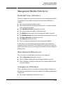
How the Management Modules Interact . . . . . . . . . . . . . . . . . . . . . . . 15-4
Using Redundant Management . . . . . . . . . . . . . . . . . . . . . . . . . . . . . . . . 15-5
Displaying Redundancy Status . . . . . . . . . . . . . . . . . . . . . . . . . . . . . . . 15-5
Enabling or Disabling Redundant Management . . . . . . . . . . . . . . . . . 15-6
Directing the Standby Module to Become Active . . . . . . . . . . . . . . . . 15-8
Setting the Active Management Module for Next Boot . . . . . . . . . . . 15-9
Enabling and Disabling Fabric Modules . . . . . . . . . . . . . . . . . . . . . . . 15-12
Management Module Switchover . . . . . . . . . . . . . . . . . . . . . . . . . . . . . 15-13
Events that Cause a Switchover . . . . . . . . . . . . . . . . . . . . . . . . . . . . . 15-13
When Switchover Will not Occur . . . . . . . . . . . . . . . . . . . . . . . . . . . . 15-13
Consequences of Switchover . . . . . . . . . . . . . . . . . . . . . . . . . . . . . . . . 15-13
Resetting the Management Module . . . . . . . . . . . . . . . . . . . . . . . . . . . 15-14
Hotswapping Management Modules . . . . . . . . . . . . . . . . . . . . . . . . . . 15-15
Hotswapping Out the Active Management Module . . . . . . . . . . . . . 15-15
xiv
When the Standby Module is not Available . . . . . . . . . . . . . . . . 15-16
Hotswapping In a Management Module . . . . . . . . . . . . . . . . . . . . . . . 15-16
Software Version Mismatch Between Active
and Hotswapped Module . . . . . . . . . . . . . . . . . . . . . . . . . . . . . . . . . . . 15-16
Downloading a New Software Version . . . . . . . . . . . . . . . . . . . . . . . . 15-17
File Synchronization after Downloading . . . . . . . . . . . . . . . . . . . . . . 15-17
Potential Software Version Mismatches
After Downloading . . . . . . . . . . . . . . . . . . . . . . . . . . . . . . . . . . . . . . . . 15-18
Downloading a Software Version
Serially if the Management Module is Corrupted . . . . . . . . . . . . . . 15-21
Turning Off Redundant Management . . . . . . . . . . . . . . . . . . . . . . . . . 15-21
Disabling Redundancy with Two Modules Present . . . . . . . . . . . . . 15-21
Disabling Redundancy With Only One Module Present . . . . . . . . . . 15-22
Displaying Management Information . . . . . . . . . . . . . . . . . . . . . . . . . 15-23
Active Management Module Commands . . . . . . . . . . . . . . . . . . . . . . 15-23
Show Modules . . . . . . . . . . . . . . . . . . . . . . . . . . . . . . . . . . . . . . . . 15-23
Show Redundancy . . . . . . . . . . . . . . . . . . . . . . . . . . . . . . . . . . . . . 15-24
Show Flash . . . . . . . . . . . . . . . . . . . . . . . . . . . . . . . . . . . . . . . . . . . 15-25
Show Version . . . . . . . . . . . . . . . . . . . . . . . . . . . . . . . . . . . . . . . . . 15-25
Show Log . . . . . . . . . . . . . . . . . . . . . . . . . . . . . . . . . . . . . . . . . . . . . 15-26
Standby Management Module Commands . . . . . . . . . . . . . . . . . . . . . 15-27
Show Redundancy . . . . . . . . . . . . . . . . . . . . . . . . . . . . . . . . . . . . . 15-27
Show Flash . . . . . . . . . . . . . . . . . . . . . . . . . . . . . . . . . . . . . . . . . . . 15-27
Show Version . . . . . . . . . . . . . . . . . . . . . . . . . . . . . . . . . . . . . . . . . 15-28
Existing CLI Commands Affected by Redundant Management . 15-29
Boot Command . . . . . . . . . . . . . . . . . . . . . . . . . . . . . . . . . . . . . . . . . . . 15-29
Setting the Default Flash for Boot . . . . . . . . . . . . . . . . . . . . . . . . . . . 15-31
Reload Command . . . . . . . . . . . . . . . . . . . . . . . . . . . . . . . . . . . . . . . . . 15-32
Additional Commands Affected by Redundant Management . . . . . 15-34
Using the Web Browser for Redundant Management . . . . . . . . . . . 15-36
Identity Page . . . . . . . . . . . . . . . . . . . . . . . . . . . . . . . . . . . . . . . . . . . . . 15-36
Overview Page . . . . . . . . . . . . . . . . . . . . . . . . . . . . . . . . . . . . . . . . . . . . 15-37
Redundancy Status Page . . . . . . . . . . . . . . . . . . . . . . . . . . . . . . . . . . . 15-37
Device View Page . . . . . . . . . . . . . . . . . . . . . . . . . . . . . . . . . . . . . . . . . 15-38
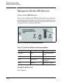
Management Module LED Behavior . . . . . . . . . . . . . . . . . . . . . . . . . . 15-40
xv
Active (Actv) LED Behavior . . . . . . . . . . . . . . . . . . . . . . . . . . . . . . . . 15-40
Standby Led Behavior . . . . . . . . . . . . . . . . . . . . . . . . . . . . . . . . . . . . . . 15-40
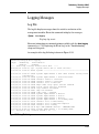
Logging Messages . . . . . . . . . . . . . . . . . . . . . . . . . . . . . . . . . . . . . . . . . . . 15-41
Log File . . . . . . . . . . . . . . . . . . . . . . . . . . . . . . . . . . . . . . . . . . . . . . . . . . 15-41
Crash Files . . . . . . . . . . . . . . . . . . . . . . . . . . . . . . . . . . . . . . . . . . . . . . . 15-42
Displaying Saved Crash Information . . . . . . . . . . . . . . . . . . . . . . . . . 15-42
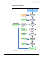
Notes on How the Active Module is Determined . . . . . . . . . . . . . . . 15-44
Diagram of Decision Process . . . . . . . . . . . . . . . . . . . . . . . . . . . . 15-45
Event Log Messages . . . . . . . . . . . . . . . . . . . . . . . . . . . . . . . . . . . . . . . . . 15-46
A File Transfers
Contents . . . . . . . . . . . . . . . . . . . . . . . . . . . . . . . . . . . . . . . . . . . . . . . . . . . . . A-1
Overview . . . . . . . . . . . . . . . . . . . . . . . . . . . . . . . . . . . . . . . . . . . . . . . . . . . . A-4
Downloading Switch Software . . . . . . . . . . . . . . . . . . . . . . . . . . . . . . . . A-4
General Software Download Rules . . . . . . . . . . . . . . . . . . . . . . . . . . . . A-5
Using TFTP To Download Software from a Server . . . . . . . . . . . . . . A-5
Menu: TFTP Download from a Server to Primary Flash . . . . . . . A-6
CLI: TFTP Download from a Server to Flash . . . . . . . . . . . . . . . . A-8
Enabling TFTP . . . . . . . . . . . . . . . . . . . . . . . . . . . . . . . . . . . . . . . . A-10
Using Auto-TFTP . . . . . . . . . . . . . . . . . . . . . . . . . . . . . . . . . . . . . . A-11
Using Secure Copy and SFTP . . . . . . . . . . . . . . . . . . . . . . . . . . . . . . . A-12
How It Works . . . . . . . . . . . . . . . . . . . . . . . . . . . . . . . . . . . . . . . . . A-13
The SCP/SFTP Process . . . . . . . . . . . . . . . . . . . . . . . . . . . . . . . . . . . . A-13
Disable TFTP and Auto-TFTP for Enhanced Security . . . . . . . A-14
Command Options . . . . . . . . . . . . . . . . . . . . . . . . . . . . . . . . . . . . . A-15
Authentication . . . . . . . . . . . . . . . . . . . . . . . . . . . . . . . . . . . . . . . . A-16
SCP/SFTP Operating Notes . . . . . . . . . . . . . . . . . . . . . . . . . . . . . A-16
Troubleshooting SSH, SFTP, and SCP Operations . . . . . . . . . . A-18
Using Xmodem to Download Switch Software From a PC or UNIX Workstation . . . . . . . . . . . . . . . . . . . . . . . . . . . . . . . . . . . . . . . . . . . . . . A-20
Menu: Xmodem Download to Primary Flash . . . . . . . . . . . . . . . A-20
CLI: Xmodem Download from a PC or UNIX Workstation to
Primary or Secondary Flash . . . . . . . . . . . . . . . . . . . . . . . . . . . . . A-21
Using USB to Transfer Files to and from the Switch . . . . . . . . . . . . A-22
xvi
Using USB to Download Switch Software . . . . . . . . . . . . . . . . . A-23
Switch-to-Switch Download . . . . . . . . . . . . . . . . . . . . . . . . . . . . . . . . A-24
Menu: Switch-to-Switch Download to Primary Flash . . . . . . . . A-25
CLI: Switch-To-Switch Downloads . . . . . . . . . . . . . . . . . . . . . . . A-26
Using PCM+ to Update Switch Software . . . . . . . . . . . . . . . . . . . . . . A-27
Copying Software Images . . . . . . . . . . . . . . . . . . . . . . . . . . . . . . . . . . . . A-28
TFTP: Copying a Software Image to a Remote Host . . . . . . . . . A-28
Xmodem: Copying a Software Image from the Switch to a
Serially Connected PC or UNIX Workstation . . . . . . . . . . . . . . . A-28
USB: Copying a Software Image to a USB Device . . . . . . . . . . . A-29
Transferring Switch Configurations . . . . . . . . . . . . . . . . . . . . . . . . . . A-29
TFTP: Copying a Configuration File to a Remote Host . . . . . . . A-30
TFTP: Copying a Configuration File from a Remote Host . . . . A-31
TFTP: Copying a Customized Command File to a Switch . . . . A-31
Xmodem: Copying a Configuration File to a Serially
Connected PC or UNIX Workstation . . . . . . . . . . . . . . . . . . . . . . A-33
Xmodem: Copying a Configuration File from a Serially
Connected PC or UNIX Workstation . . . . . . . . . . . . . . . . . . . . . . A-33
USB: Copying a Configuration File to a USB Device . . . . . . . . . A-35
USB: Copying a Configuration File from a USB Device . . . . . . A-35
Transferring ACL Command Files . . . . . . . . . . . . . . . . . . . . . . . . . . . . A-36
TFTP: Uploading an ACL Command File from a TFTP Server
A-36
Xmodem: Uploading an ACL Command File from a Serially
Connected PC or UNIX Workstation . . . . . . . . . . . . . . . . . . . . . . A-38
USB: Uploading an ACL Command File from a USB Device . . A-38
Copying Diagnostic Data to a Remote
Host, USB Device, PC or UNIX Workstation . . . . . . . . . . . . . . . . . . . A-39
Copying Command Output to a Destination Device . . . . . . . . . A-40
Copying Event Log Output to a Destination Device . . . . . . . . . A-41
Copying Crash Data Content to a Destination Device . . . . . . . A-41
Copying Crash Log Data Content to a Destination Device . . . . A-43
Enabling or Disabling the USB Port . . . . . . . . . . . . . . . . . . . . . . . . . . A-45
Behavior of Autorun When USB Port is Disabled . . . . . . . . . . . . . . . A-46
Software Versions K.13.XX Operation . . . . . . . . . . . . . . . . . . . . . A-46
Software Version K.14.XX Operation . . . . . . . . . . . . . . . . . . . . . A-46
xvii
Using USB Autorun . . . . . . . . . . . . . . . . . . . . . . . . . . . . . . . . . . . . . . . . . . A-47
How It Works . . . . . . . . . . . . . . . . . . . . . . . . . . . . . . . . . . . . . . . . . . . . . A-47
Security Considerations . . . . . . . . . . . . . . . . . . . . . . . . . . . . . . . . A-48
Troubleshooting Autorun Operations . . . . . . . . . . . . . . . . . . . . . A-49
Configuring Autorun on the Switch . . . . . . . . . . . . . . . . . . . . . . . . . . A-50
Enabling Secure Mode . . . . . . . . . . . . . . . . . . . . . . . . . . . . . . . . . . A-50
Operating Notes and Restrictions . . . . . . . . . . . . . . . . . . . . . . . . A-51
Autorun and Configuring Passwords . . . . . . . . . . . . . . . . . . . . . . A-51
Viewing Autorun Configuration Information . . . . . . . . . . . . . . . . . . . A-52
B Monitoring and Analyzing Switch Operation
Contents . . . . . . . . . . . . . . . . . . . . . . . . . . . . . . . . . . . . . . . . . . . . . . . . . . . . . B-1
Overview . . . . . . . . . . . . . . . . . . . . . . . . . . . . . . . . . . . . . . . . . . . . . . . . . . . . B-4
Status and Counters Data . . . . . . . . . . . . . . . . . . . . . . . . . . . . . . . . . . . . B-5
Menu Access To Status and Counters . . . . . . . . . . . . . . . . . . . . . . . . . B-6
General System Information . . . . . . . . . . . . . . . . . . . . . . . . . . . . . . . . . B-7
Menu Access . . . . . . . . . . . . . . . . . . . . . . . . . . . . . . . . . . . . . . . . . . . B-7
CLI Access to System Information . . . . . . . . . . . . . . . . . . . . . . . . B-8
Task Monitor—Collecting Processor Data . . . . . . . . . . . . . . . . . . . . . B-9
Switch Management Address Information . . . . . . . . . . . . . . . . . . . . . B-10
Menu Access . . . . . . . . . . . . . . . . . . . . . . . . . . . . . . . . . . . . . . . . . . B-10
CLI Access . . . . . . . . . . . . . . . . . . . . . . . . . . . . . . . . . . . . . . . . . . . . B-11
Module Information . . . . . . . . . . . . . . . . . . . . . . . . . . . . . . . . . . . . . . . B-12
Menu: Displaying Port Status . . . . . . . . . . . . . . . . . . . . . . . . . . . . B-12
CLI Access . . . . . . . . . . . . . . . . . . . . . . . . . . . . . . . . . . . . . . . . . . . . B-13
Port Status . . . . . . . . . . . . . . . . . . . . . . . . . . . . . . . . . . . . . . . . . . . . . . . B-14
Menu: Displaying Port Status . . . . . . . . . . . . . . . . . . . . . . . . . . . . B-14
CLI Access . . . . . . . . . . . . . . . . . . . . . . . . . . . . . . . . . . . . . . . . . . . . B-15
Web Access . . . . . . . . . . . . . . . . . . . . . . . . . . . . . . . . . . . . . . . . . . . B-15
Viewing Port and Trunk Group Statistics and Flow Control Status B-15
Menu Access to Port and Trunk Statistics . . . . . . . . . . . . . . . . . B-17
CLI Access To Port and Trunk Group Statistics . . . . . . . . . . . . B-18
Web Browser Access To View Port and Trunk Group Statistics B-19
Viewing the Switch’s MAC Address Tables . . . . . . . . . . . . . . . . . . . . B-19
Menu Access to the MAC Address Views and Searches . . . . . . B-19
xviii
CLI Access for MAC Address Views and Searches . . . . . . . . . . B-22
Spanning Tree Protocol (MSTP) Information . . . . . . . . . . . . . . . . . . B-23
CLI Access to MSTP Data . . . . . . . . . . . . . . . . . . . . . . . . . . . . . . . B-23
Internet Group Management Protocol (IGMP) Status . . . . . . . . . . . B-24
VLAN Information . . . . . . . . . . . . . . . . . . . . . . . . . . . . . . . . . . . . . . . . . B-25
Web Browser Interface Status Information . . . . . . . . . . . . . . . . . . . . B-27
Traffic Mirroring . . . . . . . . . . . . . . . . . . . . . . . . . . . . . . . . . . . . . . . . . . . . B-28
Mirroring Terminology . . . . . . . . . . . . . . . . . . . . . . . . . . . . . . . . . . . . . B-30
Mirrored Traffic Destinations . . . . . . . . . . . . . . . . . . . . . . . . . . . . . . . B-33
Local Destinations . . . . . . . . . . . . . . . . . . . . . . . . . . . . . . . . . . . . . B-33
Remote Destinations . . . . . . . . . . . . . . . . . . . . . . . . . . . . . . . . . . . B-33
Monitored Traffic Sources . . . . . . . . . . . . . . . . . . . . . . . . . . . . . . . . . . B-33
Criteria for Selecting Mirrored Traffic . . . . . . . . . . . . . . . . . . . . . . . . B-34
Mirroring Session Limits . . . . . . . . . . . . . . . . . . . . . . . . . . . . . . . . . . . B-34
Mirroring Sessions . . . . . . . . . . . . . . . . . . . . . . . . . . . . . . . . . . . . . . . . B-34
Mirroring Configuration . . . . . . . . . . . . . . . . . . . . . . . . . . . . . . . . . . . . B-35
Remote Mirroring Endpoint and Intermediate Devices . . . . . . B-36
Migration to Release K.12.xx . . . . . . . . . . . . . . . . . . . . . . . . . . . . B-37
Migration to Release K.14.01 or Greater . . . . . . . . . . . . . . . . . . . B-37
Using the Menu or Web Interface To Configure Local Mirroring . . B-39
Menu and Web Interface Limits . . . . . . . . . . . . . . . . . . . . . . . . . . B-39
Configuration Steps . . . . . . . . . . . . . . . . . . . . . . . . . . . . . . . . . . . . B-40
CLI: Configuring Local and Remote Mirroring . . . . . . . . . . . . . . . . . B-43
Local Mirroring Overview . . . . . . . . . . . . . . . . . . . . . . . . . . . . . . . B-44
Remote Mirroring Overview . . . . . . . . . . . . . . . . . . . . . . . . . . . . . B-46
1. Determine the Mirroring Session and Destination . . . . . . . . . . . . B-49
2. Configure a Mirroring Destination on a Remote Switch . . . . . . . B-50
3. Configure a Mirroring Session on the Source Switch . . . . . . . . . . B-52
4. Configure the Monitored Traffic in a Mirror Session . . . . . . . . . . B-55
Traffic Selection Options . . . . . . . . . . . . . . . . . . . . . . . . . . . . . . . B-55
Mirroring-Source Restrictions . . . . . . . . . . . . . . . . . . . . . . . . . . . B-56
Selecting All Inbound/Outbound Traffic to Mirror . . . . . . . . . . . . . . B-57
Port Interface with Traffic Direction as the Selection Criteria
B-57
Untagged Mirrored Packets . . . . . . . . . . . . . . . . . . . . . . . . . . . . . B-59
VLAN Interface with Traffic Direction as the Selection Criteria B-61
xix
Selecting Inbound Traffic Using an ACL (Deprecated) . . . . . . . . . . B-62
Selecting Inbound/Outbound Traffic Using a MAC Address . . . . . B-63
Selecting Inbound Traffic Using Advanced
Classifier-Based Mirroring . . . . . . . . . . . . . . . . . . . . . . . . . . . . . . . . . B-66
Classifier-Based Mirroring Configuration . . . . . . . . . . . . . . . . . . B-67
Viewing a Classifier-Based Mirroring Configuration . . . . . . . . . B-73
Classifier-Based Mirroring Restrictions . . . . . . . . . . . . . . . . . . . B-73
Applying Multiple Mirroring Sessions to an Interface . . . . . . . . B-75
Displaying a Mirroring Configuration . . . . . . . . . . . . . . . . . . . . . . . . . B-76
Displaying All Mirroring Sessions Configured on the Switch . B-76
Displaying the Remote Endpoints Configured on the Switch . B-78
Displaying the Mirroring Configuration for a Specific Session
B-79
Displaying Resource Usage for Mirroring Policies . . . . . . . . . . B-84
Viewing the Mirroring Configurations in the Running
Configuration File . . . . . . . . . . . . . . . . . . . . . . . . . . . . . . . . . . . . . B-86
Mirroring Configuration Examples . . . . . . . . . . . . . . . . . . . . . . . . . . . B-87
Example: Local Mirroring Using Traffic-Direction Criteria . . . B-87
Example: Remote Mirroring Using a Classifier-Based Policy . B-88
Example: Remote Mirroring Using Traffic-Direction Criteria . B-90
Maximum Supported Frame Size . . . . . . . . . . . . . . . . . . . . . . . . . . . . B-92
Enabling Jumbo Frames To Increase the Mirroring Path MTU B-93
Effect of Downstream VLAN Tagging on Untagged, Mirrored Traffic . . . . . . . . . . . . . . . . . . . . . . . . . . . . . . . . . . . . . . . B-94
Operating Notes for Traffic Mirroring . . . . . . . . . . . . . . . . . . . . . . . . B-95
Troubleshooting Traffic Mirroring . . . . . . . . . . . . . . . . . . . . . . . . . . . B-97
C Troubleshooting
Contents . . . . . . . . . . . . . . . . . . . . . . . . . . . . . . . . . . . . . . . . . . . . . . . . . . . . . C-1
Overview . . . . . . . . . . . . . . . . . . . . . . . . . . . . . . . . . . . . . . . . . . . . . . . . . . . . C-4
Troubleshooting Approaches . . . . . . . . . . . . . . . . . . . . . . . . . . . . . . . . . . C-5
Browser or Telnet Access Problems . . . . . . . . . . . . . . . . . . . . . . . . . . . C-6
Unusual Network Activity . . . . . . . . . . . . . . . . . . . . . . . . . . . . . . . . . . . . C-8
General Problems . . . . . . . . . . . . . . . . . . . . . . . . . . . . . . . . . . . . . . . . . . C-8
802.1Q Prioritization Problems . . . . . . . . . . . . . . . . . . . . . . . . . . . . . . . C-9
ACL Problems . . . . . . . . . . . . . . . . . . . . . . . . . . . . . . . . . . . . . . . . . . . . . C-9
xx
IGMP-Related Problems . . . . . . . . . . . . . . . . . . . . . . . . . . . . . . . . . . . . C-14
LACP-Related Problems . . . . . . . . . . . . . . . . . . . . . . . . . . . . . . . . . . . . C-14
Mesh-Related Problems . . . . . . . . . . . . . . . . . . . . . . . . . . . . . . . . . . . . C-15
Port-Based Access Control (802.1X)-Related Problems . . . . . . . . . C-15
QoS-Related Problems . . . . . . . . . . . . . . . . . . . . . . . . . . . . . . . . . . . . . C-18
Radius-Related Problems . . . . . . . . . . . . . . . . . . . . . . . . . . . . . . . . . . . C-18
Spanning-Tree Protocol (MSTP) and Fast-Uplink Problems . . . . . . C-19
SSH-Related Problems . . . . . . . . . . . . . . . . . . . . . . . . . . . . . . . . . . . . . C-20
TACACS-Related Problems . . . . . . . . . . . . . . . . . . . . . . . . . . . . . . . . . C-22
TimeP, SNTP, or Gateway Problems . . . . . . . . . . . . . . . . . . . . . . . . . C-24
VLAN-Related Problems . . . . . . . . . . . . . . . . . . . . . . . . . . . . . . . . . . . . C-24
Fan Failure . . . . . . . . . . . . . . . . . . . . . . . . . . . . . . . . . . . . . . . . . . . . . . . C-26
Using the Event Log for Troubleshooting Switch Problems . . . . C-27
Event Log Entries . . . . . . . . . . . . . . . . . . . . . . . . . . . . . . . . . . . . . . . . . C-27
Menu: Displaying and Navigating in the Event Log . . . . . . . . . . . . . C-35
CLI: Displaying the Event Log . . . . . . . . . . . . . . . . . . . . . . . . . . . . . . . C-36
CLI: Clearing Event Log Entries . . . . . . . . . . . . . . . . . . . . . . . . . . . . . C-36
CLI: Turning Event Numbering On . . . . . . . . . . . . . . . . . . . . . . . . . . . C-37
Using Log Throttling to Reduce Duplicate Event
Log and SNMP Messages . . . . . . . . . . . . . . . . . . . . . . . . . . . . . . . . . . . C-37
Log Throttle Periods . . . . . . . . . . . . . . . . . . . . . . . . . . . . . . . . . . . C-38
Example of Log Throttling . . . . . . . . . . . . . . . . . . . . . . . . . . . . . . C-38
Example of Event Counter Operation . . . . . . . . . . . . . . . . . . . . . C-40
Debug/Syslog Operation . . . . . . . . . . . . . . . . . . . . . . . . . . . . . . . . . . . . . C-41
Debug/Syslog Messaging . . . . . . . . . . . . . . . . . . . . . . . . . . . . . . . . . . . C-41
Debug/Syslog Destination Devices . . . . . . . . . . . . . . . . . . . . . . . . . . . C-41
Debug/Syslog Configuration Commands . . . . . . . . . . . . . . . . . . . . . . C-42
Configuring Debug/Syslog Operation . . . . . . . . . . . . . . . . . . . . . . . . . C-44
Displaying a Debug/Syslog Configuration . . . . . . . . . . . . . . . . . . C-46
Debug Command . . . . . . . . . . . . . . . . . . . . . . . . . . . . . . . . . . . . . . . . . . C-50
Debug Messages . . . . . . . . . . . . . . . . . . . . . . . . . . . . . . . . . . . . . . . C-50
Debug Destinations . . . . . . . . . . . . . . . . . . . . . . . . . . . . . . . . . . . . C-52
Logging Command . . . . . . . . . . . . . . . . . . . . . . . . . . . . . . . . . . . . . . . . C-54
Configuring a Syslog Server . . . . . . . . . . . . . . . . . . . . . . . . . . . . . C-55
Adding a Description for a Syslog Server . . . . . . . . . . . . . . . . . . . . . . C-57
xxi
Adding a Priority Description . . . . . . . . . . . . . . . . . . . . . . . . . . . . . . . C-58
Configuring the Severity Level for Event Log
Messages Sent to a Syslog Server . . . . . . . . . . . . . . . . . . . . . . . . . . . . C-59
Configuring the System Module Used to Select the Event Log Messages Sent to a Syslog Server . . . . . . . . . . . . . . . . . . . . . . . . C-60
Operating Notes for Debug and Syslog . . . . . . . . . . . . . . . . . . . . . . . C-60
Diagnostic Tools . . . . . . . . . . . . . . . . . . . . . . . . . . . . . . . . . . . . . . . . . . . . C-62
Port Auto-Negotiation . . . . . . . . . . . . . . . . . . . . . . . . . . . . . . . . . . . . . . C-63
Ping and Link Tests . . . . . . . . . . . . . . . . . . . . . . . . . . . . . . . . . . . . . . . . C-63
Web: Executing Ping or Link Tests . . . . . . . . . . . . . . . . . . . . . . . C-64
CLI: Ping Test . . . . . . . . . . . . . . . . . . . . . . . . . . . . . . . . . . . . . . . . . C-65
Link Tests . . . . . . . . . . . . . . . . . . . . . . . . . . . . . . . . . . . . . . . . . . . . C-66
Traceroute Command . . . . . . . . . . . . . . . . . . . . . . . . . . . . . . . . . . . . . . C-67
Viewing Switch Configuration and Operation . . . . . . . . . . . . . . . . . C-71
CLI: Viewing the Startup or Running Configuration File . . . . . . . . . C-71
Web: Viewing the Configuration File . . . . . . . . . . . . . . . . . . . . . . . . . C-71
CLI: Viewing a Summary of Switch Operational Data . . . . . . . . . . . C-72
Saving show tech Command Output to a Text File . . . . . . . . . . C-73
Customizing show tech Command Output . . . . . . . . . . . . . . . . . C-75
CLI: Viewing More Information on Switch Operation . . . . . . . . . . . C-78
Pattern Matching When Using the Show Command . . . . . . . . . C-79
CLI: Useful Commands for Troubleshooting Sessions . . . . . . . . . . . C-82
Restoring the Factory-Default Configuration . . . . . . . . . . . . . . . . . C-83
CLI: Resetting to the Factory-Default Configuration . . . . . . . . . . . . C-83
Clear/Reset: Resetting to the Factory-Default Configuration . . . . . C-83
Restoring a Flash Image . . . . . . . . . . . . . . . . . . . . . . . . . . . . . . . . . . . . . C-84
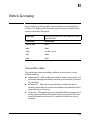
DNS Resolver . . . . . . . . . . . . . . . . . . . . . . . . . . . . . . . . . . . . . . . . . . . . . . . C-87
Terminology . . . . . . . . . . . . . . . . . . . . . . . . . . . . . . . . . . . . . . . . . . C-87
Basic Operation . . . . . . . . . . . . . . . . . . . . . . . . . . . . . . . . . . . . . . . . . . . C-88
Configuring and Using DNS Resolution with
DNS-Compatible Commands . . . . . . . . . . . . . . . . . . . . . . . . . . . . . . . . C-89
Configuring a DNS Entry . . . . . . . . . . . . . . . . . . . . . . . . . . . . . . . . . . . C-90
Example Using DNS Names with Ping and Traceroute . . . . . . . . . . C-91
Viewing the Current DNS Configuration . . . . . . . . . . . . . . . . . . . . . . C-93
Operating Notes . . . . . . . . . . . . . . . . . . . . . . . . . . . . . . . . . . . . . . . . . . . C-94
xxii
Event Log Messages . . . . . . . . . . . . . . . . . . . . . . . . . . . . . . . . . . . . . . . C-95
Locator LED (Locating a Switch) . . . . . . . . . . . . . . . . . . . . . . . . . . . . C-96
D MAC Address Management
Contents . . . . . . . . . . . . . . . . . . . . . . . . . . . . . . . . . . . . . . . . . . . . . . . . . . . . . D-1
Overview . . . . . . . . . . . . . . . . . . . . . . . . . . . . . . . . . . . . . . . . . . . . . . . . . . . . D-2
Determining MAC Addresses . . . . . . . . . . . . . . . . . . . . . . . . . . . . . . . . . . D-3
Menu: Viewing the Switch’s MAC Addresses . . . . . . . . . . . . . . . . . . . . D-4
CLI: Viewing the Port and VLAN MAC Addresses . . . . . . . . . . . . . . . . D-5
Viewing the MAC Addresses of Connected Devices . . . . . . . . . . . . . D-7
E Monitoring Resources
Contents . . . . . . . . . . . . . . . . . . . . . . . . . . . . . . . . . . . . . . . . . . . . . . . . . . . . . E-1
Viewing Information on Resource Usage . . . . . . . . . . . . . . . . . . . . . . . E-2
Policy Enforcement Engine . . . . . . . . . . . . . . . . . . . . . . . . . . . . . . . . . . E-2
Displaying Current Resource Usage . . . . . . . . . . . . . . . . . . . . . . . . . . . E-4
When Insufficient Resources Are Available . . . . . . . . . . . . . . . . . . . . E-7
F Daylight Savings Time on ProCurve Switches
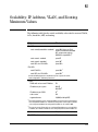
G Scalability: IP Address, VLAN, and Routing Maximum
Values
H Switch Licensing
General Procedure . . . . . . . . . . . . . . . . . . . . . . . . . . . . . . . . . . . . . . . . . H-1
I Power-Saving Features
Contents . . . . . . . . . . . . . . . . . . . . . . . . . . . . . . . . . . . . . . . . . . . . . . . . . . . I-1
Overview . . . . . . . . . . . . . . . . . . . . . . . . . . . . . . . . . . . . . . . . . . . . . . . . . . . I-2
Configuring the Power-Saving Options . . . . . . . . . . . . . . . . . . . . . . . . . I-3
Configuring the Savepower module Option . . . . . . . . . . . . . . . . . . I-3
Configuring the Savepower LED Option . . . . . . . . . . . . . . . . . . . . . I-4
Configuring the Savepower port-low-pwr Option . . . . . . . . . . . . . I-6
xxiii
Show Savepower Commands . . . . . . . . . . . . . . . . . . . . . . . . . . . . . . I-6
J Network Out-of-Band Management (OOBM) for the 6600 Switch
Contents . . . . . . . . . . . . . . . . . . . . . . . . . . . . . . . . . . . . . . . . . . . . . . . . . . . . . . J-1
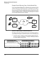
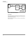
Concepts . . . . . . . . . . . . . . . . . . . . . . . . . . . . . . . . . . . . . . . . . . . . . . . . . . . . . J-2
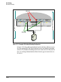
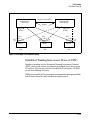
Example . . . . . . . . . . . . . . . . . . . . . . . . . . . . . . . . . . . . . . . . . . . . . . . . . . . J-4
OOBM and Switch Applications . . . . . . . . . . . . . . . . . . . . . . . . . . . . . . . J-5
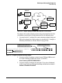
Tasks . . . . . . . . . . . . . . . . . . . . . . . . . . . . . . . . . . . . . . . . . . . . . . . . . . . . . . . . . J-6
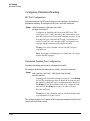
OOBM Configuration . . . . . . . . . . . . . . . . . . . . . . . . . . . . . . . . . . . . . . . . J-6
OOBM Context . . . . . . . . . . . . . . . . . . . . . . . . . . . . . . . . . . . . . . . . . . J-6
OOBM Enable/disable . . . . . . . . . . . . . . . . . . . . . . . . . . . . . . . . . . . . J-7
OOBM Port Enable/disable . . . . . . . . . . . . . . . . . . . . . . . . . . . . . . . . J-8
OOBM Port Speed Control . . . . . . . . . . . . . . . . . . . . . . . . . . . . . . . . J-9
OOBM IPv4 Address Configuration . . . . . . . . . . . . . . . . . . . . . . . . J-10
OOBM IPv4 Default Gateway Configuration . . . . . . . . . . . . . . . . J-10
OOBM Show Commands . . . . . . . . . . . . . . . . . . . . . . . . . . . . . . . . . . . . J-11
Show OOBM . . . . . . . . . . . . . . . . . . . . . . . . . . . . . . . . . . . . . . . . . . . J-11
Show OOBM IP Configuration . . . . . . . . . . . . . . . . . . . . . . . . . . . . J-12
Show OOBM ARP Information . . . . . . . . . . . . . . . . . . . . . . . . . . . . J-12
Application Server Commands . . . . . . . . . . . . . . . . . . . . . . . . . . . . . . . J-13
Application Client Commands . . . . . . . . . . . . . . . . . . . . . . . . . . . . . . . . J-14
Example . . . . . . . . . . . . . . . . . . . . . . . . . . . . . . . . . . . . . . . . . . . . . . . . . . J-15
Index
xxiv
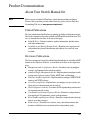
Product Documentation
About Your Switch Manual Set
Note
For the latest version of all ProCurve switch documentation, including
Release Notes covering recently added features, please visit the ProCurve
Networking Web site at www.procurve.com/manuals.
Printed Publications
The two publications listed below are printed and shipped with your switch.
The latest version of each is also available in PDF format on the ProCurve Web
site, as described in the Note at the top of this page.
■
Read Me First—Provides software update information, product notes,
and other information.
■
Installation and Getting Started Guide—Explains how to prepare for
and perform the physical installation and connect the switch to your
network.
Electronic Publications
The latest version of each of the publications listed below is available in PDF
format on the ProCurve Web site, as described in the Note at the top of this
page.
■
Management and Configuration Guide—Describes how to configure,
manage, and monitor basic switch operation.
■
Advanced Traffic Management Guide—Explains how to configure traffic
management features such as VLANs, MSTP, QoS, and Meshing.
■
Multicast and Routing Guide—Explains how to configure IGMP, PIM, IP
routing, and VRRP features.
■
Access Security Guide—Explains how to configure access security fea
tures and user authentication on the switch.
■
IPv6 Configuration Guide—Describes the IPv6 protocol operations that
are supported on the switch.
■
Command Line Interface Reference Guide—Provides a comprehensive
description of CLI commands, syntax, and operations.
■
Event Log Message Reference Guide—Provides a comprehensive descrip
tion of event log messages.
■
Release Notes—Describe new features, fixes, and enhancements that
become available between revisions of the main product guide.
xxv
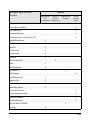
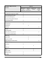
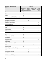
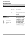
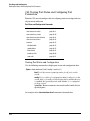
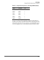
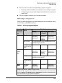
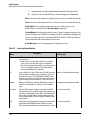
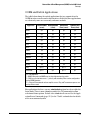
Software Feature Index
For the software manual set supporting your 3500/3500yl/5400zl/6200yl/6600/
8200zl switch model, this feature index indicates which manual to consult for
information on a given software feature.
Note
This Index does not cover IPv6 capable software features. For information on
IPv6 protocol operations and features (such as DHCPv6, DNS for IPv6, Ping6,
and MLD Snooping), refer to the IPv6 Configuration Guide.
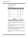
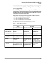
Intelligent Edge Software Features. These features are automatically
included on all switches.
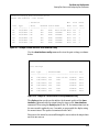
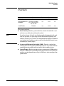
Premium License Software Features. For the HP ProCurve 3500, 3500yl,
5400zl, 6600, and 8200zl switches, Premium License features can be acquired
by purchasing the optional Premium License and installing it on the Intelligent
Edge version of these switches. (These features are automatically included on
the HP ProCurve 6200yl switches.)
Premium License Software
Features
Manual
Management
Advanced
and
Traffic
Configuration Management
Multicast and
Routing
OSPF
X
PIM-DM (Dense Mode)
X
PIM-SM (Sparse Mode)
X
QinQ (Provider Bridging)
X
VRRP
Intelligent Edge Software
Features
X
Manual
Management
Advanced
and
Traffic
Configuration Management
802.1Q VLAN Tagging
802.1X Port-Based Priority
xxvi
Access
Security
Guide
X
X
Multicast and
Routing
Access
Security
Guide
Intelligent Edge Software
Features
Manual
Management
Advanced
and
Traffic
Configuration Management
Multicast and
Routing
Access
Security
Guide
802.1X Multiple Authenticated Clients Per Port
X
Access Control Lists (ACLs)
X
AAA Authentication
X
Authorized IP Managers
X
Authorized Manager List (Web, Telnet, TFTP)
X
Auto MDIX Configuration
X
BOOTP
X
Config File
X
Console Access
X
Copy Command
X
Core Dump
X
CoS (Class of Service)
X
Debug
X
DHCP Configuration
X
DHCP Option 82
X
DHCP Snooping
X
DHCP/Bootp Operation
X
Diagnostic Tools
X
Distributed Trunking
X
Downloading Software
X
Dynamic ARP Protection
X
Dynamic Configuration Arbiter
X
Dynamic IP Lockdown
X
Eavesdrop Protection
X
Equal Cost Multi-Path (ECMP)
Event Log
X
X
xxvii
Intelligent Edge Software
Features
Manual
Management
Advanced
and
Traffic
Configuration Management
Factory Default Settings
X
Flow Control (802.3x)
X
File Management
X
File Transfers
X
Friendly Port Names
X
Guaranteed Minimum Bandwidth (GMB)
X
GVRP
X
Identity-Driven Management (IDM)
X
IGMP
X
IP Addressing
X
IP Routing
X
X
Key Management System (KMS)
X
LACP
X
LLDP
X
LLDP-MED
X
Loop Protection
MAC Address Management
Access
Security
Guide
X
Interface Access (Telnet, Console/Serial, Web)
Jumbo Packets
Multicast and
Routing
X
X
MAC Lockdown
X
MAC Lockout
X
MAC-based Authentication
X
Management VLAN
X
Meshing
X
Monitoring and Analysis
Multicast Filtering
xxviii
X
X
Intelligent Edge Software
Features
Manual
Management
Advanced
and
Traffic
Configuration Management
Multiple Configuration Files
X
Network Management Applications (SNMP)
X
Out-of-Band Management (OOBM)
X
OpenView Device Management
X
Multicast and
Routing
Passwords and Password Clear Protection
X
ProCurve Manager (PCM)
X
Ping
X
Port Configuration
X
Port Monitoring
X
Port Security
X
Port Status
X
Port Trunking (LACP)
X
Port-Based Access Control (802.1X)
Power over Ethernet (PoE and PoE+)
Access
Security
Guide
X
X
Protocol Filters
X
Protocol VLANS
X
Quality of Service (QoS)
X
RADIUS Authentication and Accounting
X
RADIUS-Based Configuration
X
Rate-Limiting
X
RIP
RMON 1,2,3,9
X
X
Routing
X
Routing - IP Static
X
SavePower Features
X
Secure Copy
X
xxix
Intelligent Edge Software
Features
Manual
Management
Advanced
and
Traffic
Configuration Management
sFlow
X
SFTP
X
SNMPv3
X
Software Downloads (SCP/SFTP, TFPT, Xmodem)
X
Multicast and
Routing
Source-Port Filters
Access
Security
Guide
X
Spanning Tree (STP, RSTP, MSTP)
X
SSHv2 (Secure Shell) Encryption
X
SSL (Secure Socket Layer)
X
Stacking (3500/3500yl/6200yl/6600 switches only)
X
Syslog
X
System Information
X
TACACS+ Authentication
X
Telnet Access
X
TFTP
X
Time Protocols (TimeP, SNTP)
X
Traffic Mirroring
X
Traffic/Security Filters
X
Troubleshooting
X
Uni-Directional Link Detection (UDLD)
X
UDP Forwarder
USB Device Support
X
X
Virus Throttling (Connection-Rate Filtering)
X
VLANs
X
VLAN Mirroring (1 static VLAN)
X
Voice VLAN
X
Web Authentication RADIUS Support
xxx
X
Intelligent Edge Software
Features
Manual
Management
Advanced
and
Traffic
Configuration Management
Web-based Authentication
Web UI
Multicast and
Routing
Access
Security
Guide
X
X
xxxi
xxxii
1
Getting Started
Contents
Introduction . . . . . . . . . . . . . . . . . . . . . . . . . . . . . . . . . . . . . . . . . . . . . . . . . . 1-2
Conventions . . . . . . . . . . . . . . . . . . . . . . . . . . . . . . . . . . . . . . . . . . . . . . . . . . 1-2
Command Syntax Statements . . . . . . . . . . . . . . . . . . . . . . . . . . . . . . . . . 1-2
Command Prompts . . . . . . . . . . . . . . . . . . . . . . . . . . . . . . . . . . . . . . . . . . 1-3
Screen Simulations . . . . . . . . . . . . . . . . . . . . . . . . . . . . . . . . . . . . . . . . . . 1-3
Configuration and Operation Examples . . . . . . . . . . . . . . . . . . . . . . . . . 1-3
Keys . . . . . . . . . . . . . . . . . . . . . . . . . . . . . . . . . . . . . . . . . . . . . . . . . . . . . . . 1-3
Sources for More Information . . . . . . . . . . . . . . . . . . . . . . . . . . . . . . . . . 1-4
Getting Documentation From the Web . . . . . . . . . . . . . . . . . . . . . . . . . 1-6
Online Help . . . . . . . . . . . . . . . . . . . . . . . . . . . . . . . . . . . . . . . . . . . . . . . . 1-6
Menu Interface . . . . . . . . . . . . . . . . . . . . . . . . . . . . . . . . . . . . . . . . . . 1-6
Command Line Interface . . . . . . . . . . . . . . . . . . . . . . . . . . . . . . . . . . 1-7
Web Browser Interface . . . . . . . . . . . . . . . . . . . . . . . . . . . . . . . . . . . 1-7
Need Only a Quick Start? . . . . . . . . . . . . . . . . . . . . . . . . . . . . . . . . . . . . . . 1-8
IP Addressing . . . . . . . . . . . . . . . . . . . . . . . . . . . . . . . . . . . . . . . . . . . . . . . 1-8
To Set Up and Install the Switch in Your Network . . . . . . . . . . . . . . . 1-8
Physical Installation . . . . . . . . . . . . . . . . . . . . . . . . . . . . . . . . . . . . . . . . . 1-8
1-1
Getting Started
Introduction
Introduction
This guide is intended for use with the following ProCurve switches:
■
8200zl switches
■
6600 switches
■
5400zl switches
■
3500, 3500yl and 6200yl switches
It describes how to use the command line interface (CLI), Menu interface, and
web browser to configure, manage, monitor, and troubleshoot switch opera
tion. For an overview of product documentation for the above switches, refer
to “Product Documentation” on page xiii. To download the switch documen
tation, visit the ProCurve Networking manuals web page at t www.hp.com/go/
procurve/manuals.
Conventions
This guide uses the following conventions for commands and screen displays.
Command Syntax Statements
Syntax: ip < default-gateway < ip-addr >> | routing >
Syntax: show interfaces [port-list ]
■
Vertical bars ( | ) separate alternative, mutually exclusive elements.
■
Square brackets ( [ ] ) indicate optional elements.
■
Braces ( < > ) enclose required elements.
■
Braces within square brackets ( [ < > ] ) indicate a required element within
an optional choice.
■
Boldface indicates use of a CLI command, part of a CLI command syntax,
or other displayed element in general text. For example:
“Use the copy tftp command to download the key from a TFTP server.”
■
1-2
Italics indicate variables for which you must supply a value when execut
ing the command. For example, in this command syntax, you must provide
one or more port numbers:
Getting Started
Conventions
Syntax: aaa port-access authenticator < port-list >
Command Prompts
In the default configuration, your switch displays a CLI prompt similar to the
following example:
ProCurve 8212zl#
To simplify recognition, this guide uses ProCurve to represent command
prompts for all switch models. For example:
ProCurve#
(You can use the hostname command to change the text in the CLI prompt.)
Screen Simulations
Displayed Text. Figures containing simulated screen text and command
output look like this:
ProCurve> show version
Image stamp:
/sw/code/build/info
March 1, 2007 13:43:13
K.12.01
139
ProCurve>
Figure 1-1. Example of a Figure Showing a Simulated Screen
In some cases, brief command-output sequences appear without figure iden
tification. For example:
ProCurve(config)# clear public-key
ProCurve(config)# show ip client-public-key
show_client_public_key: cannot stat keyfile
Configuration and Operation Examples
Unless otherwise noted, examples using a particular switch model apply to all
switch models covered by this guide.
Keys
Simulations of actual keys use a bold, sans-serif typeface with square brackets.
For example, the Tab key appears as [Tab] and the “Y” key appears as [Y].
1-3
Getting Started
Sources for More Information
Sources for More Information
For information about switch operation and features not covered in this guide,
consult the following sources:
■
Note
Feature Index—For information on which manual to consult for a given
software feature, refer to the “Software Feature Index” on page xiv.
For the latest version of all HP ProCurve switch documentation referred to
below, including Release Notes covering recently added features, visit the
ProCurve Networking manuals web page at www.hp.com/go/procurve/manuals.
■
Software Release Notes—Release Notes are posted on the HP ProCurve
Networking web site and provide information on new software updates:
•
new features and how to configure and use them
•
software management, including downloading software to the switch
•
software fixes addressed in current and previous releases
■
Product Notes and Software Update Information—The printed Read Me
First shipped with your switch provides software update information,
product notes, and other information.
■
Installation and Getting Started Guide—Use the Installation and Get
ting Started Guide shipped with your switch to prepare for and perform
the physical installation. This guide also steps you through connecting the
switch to your network and assigning IP addressing, as well as describing
the LED indications for correct operation and trouble analysis.
■
Management and Configuration Guide—Use this guide for information
on topics such as:
•
•
•
•
•
•
•
•
1-4
various interfaces available on the switch
memory and configuration operation
interface access
IP addressing
time protocols
port configuration, trunking, traffic control, and PoE operation
Redundant management
SNMP, LLDP, and other network management topics
Getting Started
Sources for More Information
•
■
Advanced Traffic Management Guide—Use this guide for information on
topics such as:
•
■
■
■
file transfers, switch monitoring, troubleshooting, and MAC address
management
VLANs: Static port-based and protocol VLANs, and dynamic GVRP
VLANs
•
spanning-Tree: 802.1D (STP), 802.1w (RSTP), and 802.1s (MSTP)
•
m
eshing
•
Quality-of-Service (QoS)
•
Access Control Lists (ACLs)
•
Out-of-Band Management (6600)
Multicast and Routing Guide—Use this guide for information on topics
such as:
•
I GMP
•
P
IM (SM and DM)
•
I P routing
•
VRRP
Access Security Guide—Use this guide for information on topics such as:
•
Local username and password security
•
Web-Based and MAC-based authentication
•
RADIUS and TACACS+ authentication
•
SSH (Secure Shell) and SSL (Secure Socket Layer) operation
•
802.1X access control
•
Port security operation with MAC-based control
•
Authorized IP Manager security
•
Key Management System (KMS)
IPv6 Configuration Guide—Use this guide for information on topics
such as:
•
Overview of IPv6 operation and features supported in software
release K.13.01 or greater
•
Configuring IPv6 addressing
•
Using IPv6 management, security, and troubleshooting features
1-5
Getting Started
Sources for More Information
Getting Documentation From the Web
To obtain the latest versions of documentation and release notes for your
switch, go to the ProCurve Networking manuals web page at www.hp.com/go/
procurve/manuals.
Online Help
Menu Interface
If you need information on specific parameters in the menu interface, refer to
the online help provided in the interface. For example:
Online Help
for Menu
Figure 1-2. Online Help for Menu Interface
1-6
Getting Started
Sources for More Information
Command Line Interface
If you need information on a specific command in the CLI, type the command
name followed by help. For example:
Figure 1-3. Example of CLI Help
Web Browser Interface
If you need information on specific features in the HP ProCurve Web Browser
Interface (hereafter referred to as the “web browser interface”), use the online
Help. You can access the Help by clicking on the “Help” text in the lower right
corner of any of the web browser interface screens.
Figure 1-4. Web Browser Interface Online Help
Note
To access the online Help for the Web browser interface, you need either
ProCurve Manager (version 1.5 or greater) installed on your network or an
active connection to the World Wide Web. Otherwise, Online help for the web
browser interface will not be available.
1-7
Getting Started
Need Only a Quick Start?
Need Only a Quick Start?
IP Addressing
If you just want to give the switch an IP address so that it can communicate
on your network, or if you are not using VLANs, ProCurve recommends that
you use the Switch Setup screen to quickly configure IP addressing. To do so,
do one of the following:
■
Enter setup at the CLI Manager level prompt.
Procurve# setup
■
In the Main Menu of the Menu interface, select
8. Run Setup
For more on using the Switch Setup screen, see the Installation and Getting
Started Guide you received with the switch.
To Set Up and Install the Switch in Your
Network
Physical Installation
Use the Installation and Getting Started Guide (shipped with the switch) for
the following:
■
Notes, cautions, and warnings related to installing and using the switch
and its related modules
■
Instructions for physically installing the switch in your network
■
Quickly assigning an IP address and subnet mask, set a Manager pass
word, and (optionally) configure other basic features.
■
Interpreting LED behavior.
For the latest version of the Installation and Getting Started Guide for your
switch, refer to “Getting Documentation From the Web” on page 1-6.
1
1-8
Selecting a Management Interface
Contents
2
Selecting a Management Interface
Contents
Overview . . . . . . . . . . . . . . . . . . . . . . . . . . . . . . . . . . . . . . . . . . . . . . . . . . . . . 2-2
Understanding Management Interfaces . . . . . . . . . . . . . . . . . . . . . . . . . 2-2
Advantages of Using the Menu Interface . . . . . . . . . . . . . . . . . . . . . . . . 2-3
Advantages of Using the CLI . . . . . . . . . . . . . . . . . . . . . . . . . . . . . . . . . . . 2-4
General Benefits . . . . . . . . . . . . . . . . . . . . . . . . . . . . . . . . . . . . . . . . . 2-4
Information on Using the CLI . . . . . . . . . . . . . . . . . . . . . . . . . . . . . . 2-4
Advantages of Using the Web Browser Interface . . . . . . . . . . . . . . . . 2-5
Advantages of Using ProCurve Manager
or ProCurve Manager Plus . . . . . . . . . . . . . . . . . . . . . . . . . . . . . . . . . . . . . 2-7
Custom Login Banners for the Console and
Web Browser Interfaces . . . . . . . . . . . . . . . . . . . . . . . . . . . . . . . . . . . . . . 2-9
Banner Operation with Telnet, Serial, or SSHv2 Access . . . . . . . . 2-9
Banner Operation with Web Browser Access . . . . . . . . . . . . . . . . 2-9
Configuring and Displaying a Non-Default Banner . . . . . . . . . . . 2-10
Example of Configuring and Displaying a Banner . . . . . . . . . . . . 2-11
Operating Notes . . . . . . . . . . . . . . . . . . . . . . . . . . . . . . . . . . . . . . . . 2-13
2-1
Selecting a Management Interface
Overview
Overview
This chapter describes the following:
■
Management interfaces for the switches covered in this guide
■
Advantages of using each interface
Understanding Management Interfaces
Management interfaces enable you to reconfigure the switch and to monitor
switch status and performance. The switch offers the following interfaces:
■
Menu interface—a menu-driven interface offering a subset of switch
commands through the built-in VT-100/ANSI console—2-3
■
CLI—a command line interface offering the full set of switch commands
through the VT-100/ANSI console built into the switch—2-4
■
Web browser interface --a switch interface offering status information
and a subset of switch commands through a standard web browser (such
as Netscape Navigator or Microsoft Internet Explorer)—2-5
■
ProCurve Manager (PCM)—a windows-based network management
solution included in-box with all manageable ProCurve devices. Features
include automatic device discovery, network status summary, topology
and mapping, and device management.
■
ProCurve Manager Plus (PCM+)—a complete windows-based
network management solution that provides both the basic features
offered with PCM, as well as more advanced management features,
including in-depth traffic analysis, group and policy management, config
uration management, device software updates, and advanced VLAN
management. (ProCurve includes a copy of PCM+ in-box for a free 30-day
trial.)
This manual describes how to use the menu interface (Chapter 3), the CLI
(Chapter 4), the web browser interface (Chapter ), and how to use these
interfaces to configure and monitor the switch.
For information on how to access the web browser interface Help, see “Online
Help for the Web Browser Interface” on page 5-12.
2-2
Selecting a Management Interface
Advantages of Using the Menu Interface
To use ProCurve Manager or ProCurve Manager Plus, refer to the Getting
Started Guide and the Administrator’s Guide, which are available electron
ically with the software for these applications. For more information, visit the
ProCurve Networking web site at www.procurve.com.
Advantages of Using the Menu Interface
Figure 2-1. Example of the Console Interface Display
■
Provides quick, easy management access to a menu-driven subset of
switch configuration and performance features:
•
•
•
•
•
IP addressing
VLANs and GVRP
Port Security
Port and Static Trunk Group
Spanning Tree
•
•
•
•
System information
Local passwords
SNMP communities
Time protocols
The menu interface also provides access for:
• Setup screen
• Event Log display
• Switch and port
status displays
■
• Switch and port statistic and counter displays
• Reboots
• Software downloads
Offers out-of-band access (through the RS-232 connection) to the
switch, so network bottlenecks, crashes, lack of configured or correct IP
address, and network downtime do not slow or prevent access
2-3
Selecting a Management Interface
Advantages of Using the CLI
■
Enables Telnet (in-band) access to the menu functionality.
■
Allows faster navigation, avoiding delays that occur with slower
display of graphical objects over a web browser interface.
■
Provides more security; configuration information and passwords are
not seen on the network.
Advantages of Using the CLI
ProCurve>
Prompt for Operator Level
ProCurve#
Prompt for Manager Level
ProCurve(config)#
Prompt for Global Configuration
Level
ProCurve(<context>)#
Prompt for Context
Configuration Levels
For example:
ProCurve(eth-1-5)#
ProCurve(vlan-1)#
ProCurve(pim)#
ProCurve(rip)#
Figure 2-2. Command Prompt Examples
General Benefits
■
Provides access to the complete set of the switch configuration, perfor
mance, and diagnostic features.
■
Offers out-of-band access (through the RS-232 connection) or Telnet (in
band) access.
■
Enables quick, detailed system configuration and management access to
system operators and administrators experienced in command prompt
interfaces.
■
Provides help at each level for determining available options and vari
ables.
Information on Using the CLI
■
2-4
For information on how to use the CLI, refer to Chapter 4. “Using the
Command Line Interface (CLI)”.
Selecting a Management Interface
Advantages of Using the Web Browser Interface
■
To perform specific procedures (such as configuring IP addressing or
VLANs), use the Contents listing at the front of the manual to locate the
information you need.
■
For monitoring and analyzing switch operation, refer to Appendix B.
■
For information on individual CLI commands, refer to the Index or to the
online Help provided in the CLI interface.
Advantages of Using the Web Browser
Interface
Figure 2-3. Example of the Web Browser Interface
■
Easy access to the switch from anywhere on the network
■
Familiar browser interface--locations of window objects consistent
with commonly used browsers, uses mouse clicking for navigation, no
terminal setup
■
Many features have all their fields in one screen so you can view all
values at once
2-5
Selecting a Management Interface
Advantages of Using the Web Browser Interface
2-6
■
More visual cues, using colors, status bars, device icons, and other
graphical objects instead of relying solely on alphanumeric values
■
Display of acceptable ranges of values available in configuration list
boxes
Selecting a Management Interface
Advantages of Using ProCurve Manager or ProCurve Manager Plus
Advantages of Using ProCurve Manager
or ProCurve Manager Plus
You can operate ProCurve Manager and ProCurve Manager Plus (PCM and
PCM+) from a PC on the network to monitor traffic, manage your hubs and
switches, and proactively recommend network changes to increase network
uptime and optimize performance. Easy to install and use, PCM and PCM+ are
the answers to your management challenges.
Figure 2-4. Example of the Home Page for ProCurve Manager Plus
2-7
Selecting a Management Interface
Advantages of Using ProCurve Manager or ProCurve Manager Plus
PCM and PCM+ enable greater control, uptime, and performance in your
network:
■
■
2-8
Features and benefits of ProCurve Manager:
•
Network Status Summary: Upon boot-up, a network status screen
displays high-level information on network devices, end nodes,
events, and traffic levels. From here, users can research any one of
these areas to get more details.
•
Alerts and Troubleshooting: An events summary screen displays
alerts to the user and categorizes them by severity, making it easier
to track where bottlenecks and issues exist in the network. Alerts
present detailed information on the problem, even down to the spe
cific port.
•
Automatic Device Discovery: This feature is customized for fast
discovery of all ProCurve manageable network devices. The user can
define which IP subnets to discover.
•
Topology and Mapping: This feature automatically creates a map of
discovered network devices. Maps are color-coded to reflect device
status and can be viewed at multiple levels (physical view, subnet
view, or VLAN view).
•
Device Management: Many device-focused tasks can be performed
directly by the software, or the user can access web-browser and
command-line interfaces with the click of a button to manage individ
ual devices from inside the tool.
Features and benefits of ProCurve Manager Plus:
•
All of the Features of ProCurve Manager: Refer to the above
listing.
•
In-Depth Traffic Analysis: An integrated, low-overhead traffic mon
itor interface shows detailed information on traffic throughout the
network. Using enhanced traffic analysis protocols such as Extended
RMON and sFlow, users can monitor overall traffic levels, segments
with the highest traffic, or even the top users within a network
segment.
•
Group and Policy Management: Changes in configuration are
tracked and logged, and archived configurations can be applied to one
or many devices. Configurations can be compared over time or
between two devices, with the differences highlighted for users.
•
Advanced VLAN Management: A new, easy-to-use VLAN manage
ment interface allows users to create and assign VLANs across the
entire network, without having to access each network device indi
vidually.
Selecting a Management Interface
Advantages of Using ProCurve Manager or ProCurve Manager Plus
•
Device Software Updates: This feature automatically obtains new
device software images from ProCurve and updates devices, allowing
users to download the latest version or choose the desired version.
Updates can be scheduled easily across large groups of devices, all at
user-specified times.
•
Investment Protection: The modular software architecture of ProCurve Manager Plus will allow ProCurve to offer network administra
tors add-on software solutions that complement their needs.
Custom Login Banners for the Console and
Web Browser Interfaces
You can now configure the switch to display a login banner of up to 3070
characters when an operator initiates a management session with the switch
through any of the following methods:
■
Telnet
■
serial connection
■
SSHv2
■
Web browser
The default banner displays product registration information; the copyright
splash is no longer displayed.
If a banner is configured, the banner page is displayed when you access the
Web user interface. The default product registration information is not
displayed as there is already a product registration prompt displayed in the
Web user interface.
Banner Operation with Telnet, Serial, or SSHv2 Access
When a system operator begins a login session, the switch displays the banner
above the local password prompt or, if no password is configured, above the
Press any key to continue prompt. Entering a correct password or, if no password
is configured, pressing any key clears the banner from the CLI and displays
the CLI prompt. (Refer to Figure 2-5 on page 2-11.)
Banner Operation with Web Browser Access
When a system operator uses a Web browser to access the switch, the text of
a non-default banner configured on the switch appears in a dedicated banner
window with a link to the Web agent home page. Clicking on To Home Page
2-9
Selecting a Management Interface
Advantages of Using ProCurve Manager or ProCurve Manager Plus
clears the banner window and prompts the user for a password (if configured).
Following entry of the correct username/password information (or if no
username/password is required), the switch then displays either the Registra
tion page or the switch’s home page. Note that if the banner feature is disabled
or if the switch is using the factory-default banner shown in figure 2-5, then
the banner page does not appear in the Web browser when an operator
initiates a login session with the switch.
Configuring and Displaying a Non-Default Banner
You can enable or disable banner operation using either the switch’s CLI or
an SNMP application. The steps include:
1. Enable non-default banner operation and define the endpoint delimiter
for the banner.
2. Enter the desired banner text, including any specific line breaks you
want.
3. Enter the endpoint delimiter.
Use show banner motd to display the current banner status.
Syntax: banner motd < delimiter >
no banner motd
This command defines the single character used to termi
nate the banner text and enables banner text input. You
can use any character except a blank space as a delimiter.
The no form of the command disables the login banner
feature.
< banner-text-string >
The switch allows up to 3070 banner characters, including blank spaces and CR-LF ([Enter]). (The tilde “ ~“ and the delimiter defined by banner motd <delimiter> are not allowed as part of the banner text.) While entering banner text, you can backspace to edit the current line (that is, a line that has not been terminated by a CR-LF.) However, terminating a line in a banner by entering a CR-LF prevents any further editing of that line. To edit a line in a banner entry after terminating the line with a CR-LF requires entering the delimiter described above and then re-configuring new banner text. The banner text string must terminate with the character defined by banner motd < delimiter >.
Note: In redundant management, the banner is not seen on the standby module, only the active module.
2-10
Selecting a Management Interface
Advantages of Using ProCurve Manager or ProCurve Manager Plus
Example of Configuring and Displaying a Banner
Suppose a system operator wanted to configure the following banner message
on her company’s switches:
This is a private system maintained by the
Allied Widget Corporation. Unauthorized use of this system can result in
civil and criminal penalties! In this case, the operator will use the [Enter] key to create line breaks, blank
spaces for line centering, and the % symbol to terminate the banner message.
Figure 2-5. Example of Configuring a Login Banner
To view the current banner configuration, use either the show banner motd or
show running command.
ProCurve(config)# show banner motd
Banner Information
Banner status: Enabled
Configured Banner:
This is a private system maintained by the
Allied Widget Corporation.
Unauthorized use of this system can result in
civil and criminal penalties!
Figure 2-6. Example of show banner motd Output
2-11
Selecting a Management Interface
Advantages of Using ProCurve Manager or ProCurve Manager Plus
Shows the current banner
configuration.
Figure 2-7. The Current Banner Appears in the Switch’s Running-Config File
The next time someone logs onto the switch’s management CLI, the following
appears:
The login screen displays the
configured banner.
Entering a correct password
clears the banner and displays
the CLI prompt.
Figure 2-8. Example of CLI Result of the Login Banner Configuration
2-12
Selecting a Management Interface
Advantages of Using ProCurve Manager or ProCurve Manager Plus
If someone uses a Web browser to log in to the switch interface, the following
message appears:
Figure 2-9. Example of Web Browser Interface Result of the Login Banner
Configuration
Operating Notes
■
The default banner appears only when the switch is in the factory
default configuration. Using no banner motd deletes the currently
configured banner text and blocks display of the default banner. The
default banner is restored only if the switch is reset to its factorydefault configuration.
■
The switch supports one banner at any time. Configuring a new
banner replaces any former banner configured on the switch.
■
If the switch is configured with ssh version 1 or ssh version 1-or-2,
configuring the banner sets the SSH configuration to ssh version 2
and displays the following message in the CLI:
Warning: SSH version has been set to v2.
■
If a banner is configured, the switch does not allow configuration with
ssh version 1 or ssh version 1-or-2. Attempting to do so produces the
following error message in the CLI:
Banner has to be disabled first.
■
If a banner is enabled on the switch, the Web browser interface
displays the following link to the banner page:
Notice to all users
2-13
Selecting a Management Interface
Advantages of Using ProCurve Manager or ProCurve Manager Plus
2-14
3
Using the Menu Interface
Contents
Overview . . . . . . . . . . . . . . . . . . . . . . . . . . . . . . . . . . . . . . . . . . . . . . . . . . . . . 3-2
Starting and Ending a Menu Session . . . . . . . . . . . . . . . . . . . . . . . . . . . 3-3
How To Start a Menu Interface Session . . . . . . . . . . . . . . . . . . . . . . . . . 3-4
How To End a Menu Session and Exit from the Console: . . . . . . . . . . 3-5
Main Menu Features . . . . . . . . . . . . . . . . . . . . . . . . . . . . . . . . . . . . . . . . . . 3-7
Screen Structure and Navigation . . . . . . . . . . . . . . . . . . . . . . . . . . . . . . . 3-9
Rebooting the Switch . . . . . . . . . . . . . . . . . . . . . . . . . . . . . . . . . . . . . . . . . 3-12
Menu Features List . . . . . . . . . . . . . . . . . . . . . . . . . . . . . . . . . . . . . . . . . . . 3-14
Where To Go From Here . . . . . . . . . . . . . . . . . . . . . . . . . . . . . . . . . . . . . . 3-15
3-1
Using the Menu Interface
Overview
Overview
This chapter describes the following features:
■
Overview of the Menu Interface (page 3-2)
■
Starting and ending a Menu session (page 3-3)
■
The Main Menu (page 3-7)
■
Screen structure and navigation (page 3-9)
■
Rebooting the switch (page 3-12)
The menu interface operates through the switch console to provide you with
a subset of switch commands in an easy-to-use menu format enabling you to:
■
Perform a “quick configuration” of basic parameters, such as the IP
addressing needed to provide management access through your network
■
Configure these features:
• M
anager and Operator
passwords
• A network monitoring port
• System parameters
• IP authorized managers
• IP addressing
• VLANs (Virtual LANs) and GVRP
• SNMP community names
• Time protocol
• Ports
• Trunk groups
■
View status, counters, and Event Log information
■
Update switch software
■
Reboot the switch
For a detailed list of menu features, see the “Menu Features List” on page 3-14.
Privilege Levels and Password Security. ProCurve strongly recom
mends that you configure a Manager password to help prevent unauthorized
access to your network. A Manager password grants full read-write access to
the switch. An Operator password, if configured, grants access to status and
counter, Event Log, and the Operator level in the CLI. After you configure
passwords on the switch and log off of the interface, access to the menu
interface (and the CLI and web browser interface) will require entry of either
the Manager or Operator password. (If the switch has only a Manager pass
word, then someone without a password can still gain read-only access.)
3-2
Using the Menu Interface
Starting and Ending a Menu Session
Note
If the switch has neither a Manager nor an Operator password, anyone
having access to the console interface can operate the console with full
manager privileges. Also, if you configure only an Operator password,
entering the Operator password enables full manager privileges.
For more information on passwords, refer to the Access Security Guide for
your switch.
Menu Interaction with Other Interfaces.
■
The menu interface displays the current running-config parameter set
tings. You can use the menu interface to save configuration changes made
in the CLI only if the CLI changes are in the running config when you save
changes made in the menu interface. (For more on how switch memory
manages configuration changes, see Chapter 6, “Switch Memory and
Configuration”.)
■
A configuration change made through any switch interface overwrites
earlier changes made through any other interface.
■
The Menu Interface and the CLI (Command Line Interface) both use the
switch console. To enter the menu from the CLI, use the menu command.
To enter the CLI from the Menu interface, select Command Line (CLI) option.)
Starting and Ending a Menu Session
You can access the menu interface using any of the following:
Note
■
A direct serial connection to the switch’s console port, as described in the
installation guide you received with the switch
■
A Telnet connection to the switch console from a networked PC or the
switch’s web browser interface. Telnet requires that an IP address and
subnet mask compatible with your network have already been configured
on the switch.
This section assumes that either a terminal device is already configured and
connected to the switch (see the Installation and Getting Started Guide
shipped with your switch) or that you have already configured an IP address
on the switch (required for Telnet access).
3-3
Using the Menu Interface
Starting and Ending a Menu Session
How To Start a Menu Interface Session
In its factory default configuration, the switch console starts with the CLI
prompt. To use the menu interface with Manager privileges, go to the Manager
level prompt and enter the menu command.
1. Use one of these methods to connect to the switch:
•
A PC terminal emulator or terminal
•
T
elnet
2. Do one of the following:
3.
•
If you are using Telnet, go to step 3.
•
If you are using a PC terminal emulator or a terminal, press [Enter] one
or more times until a prompt appears.
When the switch screen appears, do one of the following:
•
If a password has been configured, the password prompt appears.
Password: _
Type the Manager password and press [Enter]. Entering the Manager
password gives you manager-level access to the switch. (Entering the
Operator password gives you operator-level access to the switch.
Refer to the Access Security Guide for your switch.)
•
If no password has been configured, the CLI prompt appears. Go to
the next step.
4. When the CLI prompt appears, display the Menu interface by entering the
menu command. For example:
ProCurve# menu [Enter]
results in the following display:
3-4
Using the Menu Interface
Starting and Ending a Menu Session
Figure 3-1. Example of the Main Menu with Manager Privileges
For a description of Main Menu features, see “Main Menu Features” on page
3-7.
Note
To configure the switch to start with the menu interface instead of the CLI, go
to the Manager level prompt in the CLI, enter the setup command, and in the
resulting display, change the Logon Default parameter to Menu. For more infor
mation, see the Installation and Getting Started Guide you received with the
switch.
How To End a Menu Session and Exit from the Console:
The method for ending a menu session and exiting from the console depends
on whether, during the session, you made any changes to the switch configu
ration that require a switch reboot to activate. (Most changes via the menu
interface need only a Save, and do not require a switch reboot.) Configuration
changes needing a reboot are marked with an asterisk (*) next to the config
ured item in the menu and also next to the Switch Configuration item in the
Main Menu.
3-5
Using the Menu Interface
Starting and Ending a Menu Session
Asterisk indicates a
configuration change
that requires a reboot
to activate.
Figure 3-2. Example Indication of a Configuration Change Requiring a Reboot
1. In the current session, if you have not made configuration changes that
require a switch reboot to activate, return to the Main Menu and press [0]
(zero) to log out. Then just exit from the terminal program, turn off the
terminal, or quit the Telnet session.
2. If you have made configuration changes that require a switch reboot—
that is, if an asterisk (*) appears next to a configured item or next to Switch
Configuration in the Main Menu:
a. Return to the Main Menu.
b. Press [6] to select Reboot Switch and follow the instructions on the
reboot screen.
Rebooting the switch terminates the menu session, and, if you are using
Telnet, disconnects the Telnet session.
(See “Rebooting To Activate Configuration Changes” on page 3-13.)
3. Exit from the terminal program, turn off the terminal, or close the Telnet
application program.
3-6
Using the Menu Interface
Main Menu Features
Main Menu Features Figure 3-3. The Main Menu View with Manager Privileges
The Main Menu gives you access to these Menu interface features:
■
Status and Counters: Provides access to display screens showing
switch information, port status and counters, and port and VLAN address
tables. (Refer to Appendix B, “Monitoring and Analyzing Switch Opera
tion”.)
■
Switch Configuration: Provides access to configuration screens for
displaying and changing the current configuration settings. (See the Con
tents listing at the front of this manual.) For a listing of features and
parameters configurable through the menu interface, see the “Menu Fea
tures List” on page 3-14. For an index of the features covered in the
software manuals for your switch, refer to the “Software Feature Index”
on page -xxvi.
■
Console Passwords: Provides access to the screen used to set or change
Manager-level and Operator-level passwords, and to delete Manager and
Operator password protection. (Refer to the chapter on configuring usernames and passwords in the Access Security Guide for your switch.)
■
Event Log: Enables you to read progress and error messages that are
useful for checking and troubleshooting switch operation. (See “Using the
Event Log for Troubleshooting Switch Problems” on page C-27.)
3-7
Using the Menu Interface
Main Menu Features
3-8
■
Command Line (CLI): Selects the Command Line Interface at the same
level (Manager or Operator) that you are accessing in the Menu interface.
(Refer to Chapter 4, “Using the Command Line Interface (CLI)”.)
■
Reboot Switch: Performs a “warm” reboot of the switch, which clears
most temporary error conditions, resets the network activity counters to
zero, and resets the system up-time to zero. A reboot is required to activate
a change in the VLAN Support parameter. (See “Rebooting from the Menu
Interface” on page 6-11.)
■
Download OS: Enables you to download a new switch software version
to the switch. (See Appendix A, “File Transfers”.)
■
Run Setup: Displays the Switch Setup screen for quickly configuring
basic switch parameters such as IP addressing, default gateway, logon
default interface, and others. (Refer to the Installation and Getting
Started Guide for your switch.)
■
Logout: Closes the Menu interface and console session, and disconnects
Telnet access to the switch. (See “How to End a Menu Session and Exit
from the Console” on page 3-5.)
Using the Menu Interface
Screen Structure and Navigation
Screen Structure and Navigation
Menu interface screens include these three elements:
■
Parameter fields and/or read-only information such as statistics
■
Navigation and configuration actions, such as Save, Edit, and Cancel
■
Help line to describe navigation options, individual parameters, and readonly data
For example, in the following System Information screen:
Screen title – identifies
the location within the
menu structure
Parameter fields
Help describing each of the
items in the parameter fields
Actions line
Help line
describing the
selected action
or selected
parameter field
Navigation instructions
Figure 3-4. Elements of the Screen Structure
“Forms” Design. The configuration screens, in particular, operate similarly
to a number of PC applications that use forms for data entry. When you first
enter these screens, you see the current configuration for the item you have
selected. To change the configuration, the basic operation is to:
1. Press [E] to select the Edit action.
2. Navigate through the screen making all the necessary configuration
changes. (See Table 3-1 on page 3-10.)
3. Press [Enter] to return to the Actions line. From there you can save the
configuration changes or cancel the changes. Cancel returns the configu
ration to the values you saw when you first entered the screen.
3-9
Using the Menu Interface
Screen Structure and Navigation
Table 3-1.
3-10
How To Navigate in the Menu Interface
Task:
Actions:
Execute an action
from the “Actions –>”
list at the bottom of
the screen:
Use either of the following methods:
• Use the arrow keys ([<], or [>]) to highlight the action you want
to execute, then press [Enter].
• Press the key corresponding to the capital letter in the action
name. For example, in a configuration menu, press [E] to select
Edit and begin editing parameter values.
Reconfigure (edit) a
parameter setting or a
field:
1. Select a configuration item, such as System Name. (See figure
3-4.)
2. Press [E] (for Edit on the Actions line).
3. Use [Tab] or the arrow keys ([<], [>], [^], or [v]) to highlight the
item or field.
4. Do one of the following:
– If the parameter has preconfigured values, either use the
Space bar to select a new option or type the first part of your
selection and the rest of the selection appears automatically.
(The help line instructs you to “Select” a value.)
– If there are no preconfigured values, type in a value (the Help
line instructs you to “Enter” a value).
5. If you want to change another parameter value, return to step 3.
6. If you are finished editing parameters in the displayed screen,
press [Enter] to return to the Actions line and do one of the
following:
– To save and activate configuration changes, press [S] (for the
Save action). This saves the changes in the startup
configuration and also implements the change in the
currently running configuration. (See Chapter 6, “Switch
Memory and Configuration”.)
– To exit from the screen without saving any changes that you
have made (or if you have not made changes), press [C] (for
the Cancel action).
Note: In the menu interface, executing Save activates most
parameter changes and saves them in the startup configuration
(or flash) memory, and it is therefore not necessary to reboot the
switch after making these changes. But if an asterisk appears
next to any menu item you reconfigure, the switch will not
activate or save the change for that item until you reboot the
switch. In this case, rebooting should be done after you have
made all desired changes and then returned to the Main Menu.
7. When you finish editing parameters, return to the Main Menu.
8. If necessary, reboot the switch by highlighting Reboot Switch in
the Main Menu and pressing [Enter]. (See the Note, above.)
Exit from a read-only
screen.
Press [B] (for the Back action).
Using the Menu Interface
Screen Structure and Navigation
To get Help on individual parameter descriptions. In most screens
there is a Help option in the Actions line. Whenever any of the items in the
Actions line is highlighted, press [H], and a separate help screen is displayed.
For example:
Pressing [H] or highlighting Help and
pressing [Enter] displays Help for the
parameters listed in the upper part of
the screen
Highlight on any item in
the Actions line
indicates that the
Actions line is active.
The Help line provides
a brief descriptor of
the highlighted Action
item or parameter.
Figure 3-5. Example Showing How To Display Help
To get Help on the actions or data fields in each screen: Use the arrow
keys ([<], [>], [^], or [v]) to select an action or data field. The help line under the
Actions items describes the currently selected action or data field.
For guidance on how to navigate in a screen: See the instructions provided
at the bottom of the screen, or refer to “Screen Structure and Navigation” on
page 3-9.)
3-11
Using the Menu Interface
Rebooting the Switch
Rebooting the Switch
Rebooting the switch from the menu interface
■
Terminates all current sessions and performs a reset of the operating
system
■
Activates any menu interface configuration changes that require a reboot
■
Resets statistical counters to zero
(Note that statistical counters can be reset to zero without rebooting the
switch.)
To Reboot the switch, use the Reboot Switch option in the Main Menu. (Note
that Reboot Switch is not available if you log on in Operator mode; that is, if
you enter an Operator password instead of a manager password at the
password prompt.)
Reboot Switch option
Figure 3-6. The Reboot Switch Option in the Main Menu
3-12
Using the Menu Interface
Rebooting the Switch
Rebooting To Activate Configuration Changes. Configuration changes
for most parameters in the menu interface become effective as soon as you
save them. However, you must reboot the switch in order to implement a
change in the Maximum VLANs to support parameter. (To access this parameter, go
to the Main Menu and select:
2. Switch Configuration
8. VLAN Menu
1. VLAN Support.
If you make configuration changes in the menu interface that require a reboot,
the switch displays an asterisk (*) next to the menu item in which the change
has been made. For example, if you change and save the value for the Maximum
VLANs to support parameter, an asterisk appears next to the VLAN Support entry
in the VLAN Menu screen, and also next to the Switch Configuration entry in
the Main Menu.
Asterisk
indicates a
configuration
change that
requires a
reboot in order
to take effect.
Reminder to
reboot the
switch to
activate
configuration
changes.
Figure 3-7. Indication of a Configuration Change Requiring a Reboot
To activate changes indicated by the asterisk, go to the Main Menu and select
the Reboot Switch option.
Note
Executing the write memory command in the CLI does not affect pending
configuration changes indicated by an asterisk in the menu interface. That is,
only a reboot from the menu interface or a boot or reload command from the
CLI will activate a pending configuration change indicated by an asterisk.
3-13
Using the Menu Interface
Menu Features List
Menu Features List
Status and Counters
•
General System Information
•
Switch Management Address Information
•
Port Status
•
Port Counters
•
Address Table
•
Port Address Table
Switch Configuration
•
System Information
•
Port/Trunk Settings
•
Network Monitoring Port
•
IP Configuration
•
SNMP Community Names
•
IP authorized Managers
•
VLAN Menu
Console Passwords
Event Log
Command Line (CLI)
Reboot Switch
Download OS (Download Switch Software)
Run Setup
Logout
3-14
Using the Menu Interface
Where To Go From Here
Where To Go From Here
This chapter provides an overview of the menu interface and how to use it.
The following table indicates where to turn for detailed information on how
to use the individual features available through the menu interface.
Option:
Turn to:
To use the Run Setup option
Refer to the Installation and Getting Started Guide
shipped with the switch.
To view and monitor switch status and Appendix B, “Monitoring and Analyzing Switch
counters
Operation”
To learn how to configure and use
Refer to the Access Security Guide for your
passwords and other security features switch.
To learn how to use the Event Log
“Using the Event Log for Troubleshooting Switch
Problems” on page C-27
To learn how the CLI operates
Chapter 4, “Using the Command Line Interface
(CLI)”
To download switch software
Appendix A, “File Transfers”
For a description of how switch
memory handles configuration
changes
Chapter 6, “Switch Memory and Configuration”
For information on other switch
features and how to configure them
Refer to the Feature Index on (page xxvi) at the
front of this guide, and to “Sources for More
Information” on page 1-4.
3-15
Using the Menu Interface
Where To Go From Here
3-16
4
Using the Command Line Interface (CLI)
Contents
Overview . . . . . . . . . . . . . . . . . . . . . . . . . . . . . . . . . . . . . . . . . . . . . . . . . . . . . 4-2
Accessing the CLI . . . . . . . . . . . . . . . . . . . . . . . . . . . . . . . . . . . . . . . . . . . . . 4-2
Using the CLI . . . . . . . . . . . . . . . . . . . . . . . . . . . . . . . . . . . . . . . . . . . . . . . . . 4-2
Privilege Levels at Logon . . . . . . . . . . . . . . . . . . . . . . . . . . . . . . . . . . . . . 4-3
Privilege Level Operation . . . . . . . . . . . . . . . . . . . . . . . . . . . . . . . . . . . . . 4-4
Operator Privileges . . . . . . . . . . . . . . . . . . . . . . . . . . . . . . . . . . . . . . 4-4
Manager Privileges . . . . . . . . . . . . . . . . . . . . . . . . . . . . . . . . . . . . . . . 4-5
How To Move Between Levels . . . . . . . . . . . . . . . . . . . . . . . . . . . . . . . . 4-7
Listing Commands and Command Options . . . . . . . . . . . . . . . . . . . . . . 4-8
Listing Commands Available at Any Privilege Level . . . . . . . . . . . 4-8
Listing Command Options . . . . . . . . . . . . . . . . . . . . . . . . . . . . . . . 4-10
Displaying CLI “Help” . . . . . . . . . . . . . . . . . . . . . . . . . . . . . . . . . . . . . . . 4-11
Configuration Commands and the Context Configuration Modes . . 4-13
CLI Control and Editing . . . . . . . . . . . . . . . . . . . . . . . . . . . . . . . . . . . . . . 4-16
Executing a Prior Command—Redo . . . . . . . . . . . . . . . . . . . . . . . . . . 4-16
Repeating Execution of a Command . . . . . . . . . . . . . . . . . . . . . . . . . . 4-16
Using a Command Alias . . . . . . . . . . . . . . . . . . . . . . . . . . . . . . . . . . . . . 4-18
CLI Shortcut Keystrokes . . . . . . . . . . . . . . . . . . . . . . . . . . . . . . . . . . . . 4-20
4-1
Using the Command Line Interface (CLI)
Overview
Overview
The CLI is a text-based command interface for configuring and monitoring the
switch. The CLI gives you access to the switch’s full set of commands while
providing the same password protection that is used in the web browser
interface and the menu interface.
Accessing the CLI
Like the menu interface, the CLI is accessed through the switch console, and
in the switch’s factory default state, is the default interface when you start a
console session. You can access the console out-of-band by directly connect
ing a terminal device to the switch, or in-band by using Telnet either from a
terminal device or through the web browser interface.
Also, if you are using the menu interface, you can access the CLI by selecting
the Command Line (CLI) option in the Main Menu.
Using the CLI
The CLI offers these privilege levels to help protect the switch from unauthor
ized access:
Note
4-2
1.
Operator
2.
Manager
3.
Global Configuration
4.
Context Configuration
CLI commands are not case-sensitive.
Using the Command Line Interface (CLI)
Using the CLI
When you use the CLI to make a configuration change, the switch writes the
change to the Running-Config file in volatile memory. This allows you to test
your configuration changes before making them permanent. To make changes
permanent, you must use the write memory command to save them to the
Startup-Config file in non-volatile memory. If you reboot the switch without
first using write memory, all changes made since the last reboot or write memory
(whichever is later) will be lost. For more on switch memory and saving
configuration changes, see Chapter 6, “Switch Memory and Configuration”.
Privilege Levels at Logon
Privilege levels control the type of access to the CLI. To implement this
control, you must set at least a Manager password. Without a Manager
password configured, anyone having serial port, Telnet, or web browser
access to the switch can reach all CLI levels. (For more on setting passwords,
refer to the chapter on usernames and passwords in the Access Security Guide
for your switch.)
When you use the CLI to log on to the switch, and passwords are set, you will
be prompted to enter a password. For example:
Password Prompt
Figure 4-1. Example of CLI Log-On Screen with Password(s) Set
In the above case, you will enter the CLI at the level corresponding to the
password you provide (operator or manager).
If no passwords are set when you log onto the CLI, you will enter at the
Manager level. For example:
ProCurve# _
4-3
Using the Command Line Interface (CLI)
Using the CLI
Caution
ProCurve strongly recommends that you configure a Manager password. If a
Manager password is not configured, then the Manager level is not passwordprotected, and anyone having in-band or out-of-band access to the switch may
be able to reach the Manager level and compromise switch and network
security. Note that configuring only an Operator password does not prevent
access to the Manager level by intruders who have the Operator password.
Pressing the Clear button on the front of the switch removes password
protection. For this reason, it is recommended that you protect the switch
from physical access by unauthorized persons. If you are concerned about
switch security and operation, you should install the switch in a secure
location, such as a locked wiring closet.
Privilege Level Operation
Operator Privileges
1. Operator Level
Manager Privileges
2. Manager Level
3. Global Configuration
4. Context Configuration Level
Figure 4-2. Access Sequence for Privilege Levels
Operator Privileges
At the Operator level you can examine the current configuration and move
between interfaces without being able to change the configuration. A “>”
character delimits the Operator-level prompt. For example:
ProCurve> _
(Example of the Operator prompt.)
When using enable to move to the Manager level, the switch prompts you for
the Manager password if one has already been configured.
4-4
Using the Command Line Interface (CLI)
Using the CLI
Manager Privileges
Manager privileges give you three additional levels of access: Manager, Global
Configuration, and Context Configuration. A “#” character delimits any Man
ager prompt. For example:
ProCurve#_
■
Example of the Manager prompt.
Manager level: Provides all Operator level privileges plus the ability to
perform system-level actions that do not require saving changes to the
system configuration file. The prompt for the Manager level contains only
the system name and the “#” delimiter, as shown above. To select this
level, enter the enable command at the Operator prompt and enter the
Manager password, when prompted. For example:
ProCurve> enable
Password:
ProCurve# _
■
Enter enable at the Operator prompt.
CLI prompt for the Manager password.
The Manager prompt appears after the
correct Manager password is entered.
Global Configuration level: Provides all Operator and Manager level
privileges, and enables you to make configuration changes to any of the
switch’s software features. The prompt for the Global Configuration level
includes the system name and “(config)”. To select this level, enter the
config command at the Manager prompt. For example:
ProCurve# config
Enter config at the Manager prompt.
ProCurve(config)#_ The Global Config prompt.
■
Context Configuration level: Provides all Operator and Manager priv
ileges, and enables you to make configuration changes in a specific
context, such as one or more ports or a VLAN. The prompt for the Context
Configuration level includes the system name and the selected context.
For example:
ProCurve(eth-1)#
ProCurve(vlan-10)#
The Context level is useful, for example, for executing several commands
directed at the same port or VLAN, or if you want to shorten the command
strings for a specific context area. To select this level, enter the specific
context at the Global Configuration level prompt. For example, to select
the context level for an existing VLAN with the VLAN ID of 10, you would
enter the following command and see the indicated result:
ProCurve(config)# vlan 10
ProCurve(vlan-10)#
4-5
Using the Command Line Interface (CLI)
Using the CLI
Table 4-1.
Privilege Level Hierarchy
Privilege
Level
Example of Prompt and Permitted Operations
Operator Privilege
Operator Level ProCurve>
show < command >
setup
View status and configuration information.
ping < argument >
link-test < argument >
Perform connectivity tests.
enable
Move from the Operator level to the Manager
level.
menu
Move from the CLI interface to the menu interface.
logout
Exit from the CLI interface and terminate the
console session.
exit
Terminate the current session (same as logout).
Manager Privilege
Manager Level ProCurve#
Perform system-level actions such as system
control, monitoring, and diagnostic commands,
plus any of the Operator-level commands. For a list
of available commands, enter ? at the prompt.
Global
Configuration
Level
ProCurve(config)#
Execute configuration commands, plus all
Operator and Manager commands. For a list of
available commands, enter ? at the prompt.
Context
Configuration
Level
ProCurve(eth-5)#
ProCurve(vlan
100)#
Execute context-specific configuration
commands, such as a particular VLAN or switch
port. This is useful for shortening the command
strings you type, and for entering a series of
commands for the same context. For a list of
available commands, enter ? at the prompt.
4-6
Using the Command Line Interface (CLI)
Using the CLI
How To Move Between Levels
Change in Levels
Example of Prompt, Command, and Result
Operator level
to
Manager level
ProCurve> enable
Password:_
After you enter enable, the Password
prompt appears. After you enter the
Manager password, the system prompt
appears with the # symbol:
ProCurve#_
Manager level
to
Global configuration
level
ProCurve# config
ProCurve(config)#
Global configuration ProCurve(config)# vlan 10
level
ProCurve(vlan-10)#
to a
Context configuration
level
Context configuration ProCurve(vlan-10)# interface e 3
level
ProCurve(int-3)#
to another
The CLI accepts “e” as the abbreviated
Context configuration
form of “ethernet”.
level
Move from any level ProCurve(int-3)# exit
to the preceding level ProCurve(config)# exit
ProCurve# exit
ProCurve>
Move from any level
to the Manager level
ProCurve(int-3)# end
ProCurve#
—or—
ProCurve(config)# end
ProCurve#
Moving Between the CLI and the Menu Interface. When moving
between interfaces, the switch retains the current privilege level (Manager or
Operator). That is, if you are at the Operator level in the menu and select the
Command Line Interface (CLI) option from the Main Menu, the CLI prompt
appears at the Operator level.
Changing Parameter Settings. Regardless of which interface is used (CLI,
menu interface, or web browser interface), the most recently configured
version of a parameter setting overrides any earlier settings for that parameter.
4-7
Using the Command Line Interface (CLI)
Using the CLI
For example, if you use the menu interface to configure an IP address of “X”
for VLAN 1 and later use the CLI to configure a different IP address of “Y” for
VLAN 1, then “Y” replaces “X” as the IP address for VLAN 1 in the running
config file. If you subsequently execute write memory in the CLI, then the
switch also stores “Y” as the IP address for VLAN 1 in the startup-config file.
(For more on the startup-config and running config files, see Chapter 6,
“Switch Memory and Configuration”.)
Listing Commands and Command Options
At any privilege level you can:
■
List all of the commands available at that level
■
List the options for a specific command
Listing Commands Available at Any Privilege Level
At a given privilege level you can list and execute the commands that level
offers, plus all of the commands available at preceding levels. For example,
at the Operator level, you can list and execute only the Operator level com
mands. However, at the Manager level, you can list and execute the commands
available at both the Operator and Manager levels.
Type “?” To List Available Commands. 1.Typing the ? symbol lists the
commands you can execute at the current privilege level. For example,
typing ? at the Operator level produces this listing:
Figure 4-3. Example of the Operator Level Command Listing
4-8
Using the Command Line Interface (CLI)
Using the CLI
Typing ? at the Manager level produces this listing:
When - - MORE - - appears, use the Space
bar or [Return] to list additional commands.
Figure 4-4.Example of the Manager-Level Command Listing
When - - MORE - - appears, there are more commands in the listing. To list the
next screenfull of commands, press the Space bar. To list the remaining
commands one-by-one, repeatedly press [Enter].
Typing ? at the Global Configuration level or the Context Configuration level
produces similar results.
Use [Tab] To Search for or Complete a Command Word. You can use
[Tab] to help you find CLI commands or to quickly complete the current word
in a command. To do so, type one or more consecutive characters in a
command and then press [Tab] (with no spaces allowed). For example, at the
Global Configuration level, if you press [Tab] immediately after typing “t”, the
CLI displays the available command options that begin with “t”. For example:
ProCurve(config)# t [Tab]
tacacs-server
telnet-server
time
timesync
trunk
telnet
terminal
traceroute
ProCurve(config)# t
4-9
Using the Command Line Interface (CLI)
Using the CLI
As mentioned above, if you type part of a command word and press [Tab], the
CLI completes the current word (if you have typed enough of the word for the
CLI to distinguish it from other possibilities), including hyphenated exten
sions. For example:
ProCurve(config)# port-[Tab]
ProCurve(config)# port-security _
Pressing [Tab] after a completed command word lists the further options for
that command.
ProCurve(config)# qos [Tab]
udp-portSet UDP port based priority.
tcp-portSet TCP port based priority.
device-priorityConfigure device-based priority.
dscp-mapDefine mapping between a DSCP
(Differentiated-Services Codepoint)
value and 802.1p priority.
type-of-serviceConfigure the Type-of-Service
method the device uses to
prioritize IP traffic.
Listing Command Options
You can use the CLI to remind you of the options available for a command by
entering command keywords followed by ?. For example, suppose you want
to see the command options for configuring the console settings:
This example displays the command options
for configuring the switch’s console settings.
Figure 4-5. Example of How To List the Options for a Specific Command
4-10
Using the Command Line Interface (CLI)
Using the CLI
Displaying CLI “Help”
CLI Help provides two types of context-sensitive information:
■
Command list with a brief summary of each command’s purpose
■
Detailed information on how to use individual commands
Displaying Command-List Help.
Syntax: help
Displays a listing of command Help summaries for all
commands available at the current privilege level. That is, at
the Operator level, executing help displays the Help summaries
only for Operator-Level commands. At the Manager level,
executing help displays the Help summaries for both the
Operator and Manager levels, and so on.
For example, to list the Operator-Level commands with their purposes:
Figure 4-6. Example of Context-Sensitive Command-List Help
Displaying Help for an Individual Command.
Syntax: < command-string > help
This option displays Help for any command available at the
current context level.
For example, to list the Help for the interface command in the Global Config
uration privilege level:
4-11
Using the Command Line Interface (CLI)
Using the CLI
Figure 4-7.Example of How To Display Help for a Specific Command
Note that trying to list the help for an individual command from a privilege
level that does not include that command results in an error message. For
example, trying to list the help for the interface command while at the global
configuration level produces this result:
ProCurve# speed-duplex help
Invalid input: speed-duplex
4-12
Using the Command Line Interface (CLI)
Using the CLI
Configuration Commands and the Context
Configuration Modes
You can execute any configuration command in the global configuration mode
or in selected context modes. However, using a context mode enables you to
execute context-specific commands faster, with shorter command strings.
The switch offers interface (port or trunk group) and VLAN context configu
ration modes:
Port or Trunk-Group Context. Includes port- or trunk-specific commands
that apply only to the selected port(s) or trunk group, plus the global config
uration, Manager, and Operator commands. The prompt for this mode
includes the identity of the selected port(s):
ProCurve(config)# interface c3-c6
ProCurve(eth-C5-C8)#
ProCurve(config)# interface trk1
ProCurve(eth-Trk1)#
Commands executed at configuration level for entering port and
trk1 static trunk-group contexts, and resulting prompts showing
port or static trunk contexts..
ProCurve(eth-C5-C8)#
ProCurve(eth-Trk1)#
ProCurve(eth-C5-C8)# ?
ProCurve(eth-C5-C8)# ?
Lists the commands you can use in the port or static trunk context,
plus the Manager, Operator, and context commands you can exe
cute at this level.
4-13
Using the Command Line Interface (CLI)
Using the CLI
In the port context, the first block of commands in the “?”
listing show the context-specific commands that will affect
only ports C3-C6.
The remaining commands in the listing are Manager,
Operator, and context commands.
Figure 4-8. Context-Specific Commands Affecting Port Context
4-14
Using the Command Line Interface (CLI)
Using the CLI
VLAN Context . Includes VLAN-specific commands that apply only to the
selected VLAN, plus Manager and Operator commands. The prompt for this
mode includes the VLAN ID of the selected VLAN. For example, if you had
already configured a VLAN with an ID of 100 in the switch:
ProCurve(config)# vlan 100
Command executed at configuration level to enter VLAN 100 context.
ProCurve(vlan-100)#
Resulting prompt showing VLAN 100 context.
ProCurve(vlan-100)# ?
Lists commands you can use in the VLAN context, plus Manager,
Operator, and context commands you can execute at this level.
In the VLAN
context, the
first block of
commands in
the “?” listing
show the
commands that
will affect only
vlan-100.
The remaining
commands in
the listing are
Manager,
Operator, and
context
commands.
Figure 4-9. Context-Specific Commands Affecting VLAN Context
4-15
Using the Command Line Interface (CLI)
CLI Control and Editing
CLI Control and Editing
Executing a Prior Command—Redo
The redo command executes a prior command in the history list.
Syntax: redo [number | command-str]
Re-executes a command from history. Executes the last
command by default.
number: The position of the command to execute in the history
list. When number is specified, the nth command starting from
the most recent command in the history is executed.
command-str: When command-str is specified, the most recent
command whose name matches the specified string is
executed.
ProCurve(config)# show history
2
show arp
1
show flash
ProCurve(config)# redo 2
Executes the show arp command again.
IP ARP table
IP Address
--------------15.255.128.1
MAC Address
Type
Port
----------------- ------- ---
00000c-07ac00
dynamic A11
Figure 4-10. Example of the redo Command
Repeating Execution of a Command
The repeat command executes a previous command in the history list.
4-16
Using the Command Line Interface (CLI)
CLI Control and Editing
Syntax: repeat [cmdlist] [count] [delay]
Repeats execution of a previous command. Repeats the last
command by default until a key is pressed.
cmdlist: If a number or range of numbers is specified, the
command repeats the nth most recent commands (where “n”
is the position in the history list).
count: Repeats the command for the number of times specified.
delay: The command repeats execution after a delay for the
number of seconds specified.
For example:
ProCurve(config)# repeat 1-4,7-8,10 count 2 delay 3
ProCurve(config)# show history
3
show ver
2
show ip
1
show arp
ProCurve(config)# repeat 1-2
Repeats the show arp and show ip commands.
IP ARP table
IP Address
--------------15.255.128.1
MAC Address
Type
Port
----------------- ------- --000000-000000
dynamic
Internet (IP) Service
IP Routing : Disabled
Default Gateway
Default TTL
Arp Age
Domain Suffix
DNS server
:
: 64
: 20
:
:
VLAN
| IP Config IP Address
Subnet Mask
Proxy ARP
-------------------- + ---------- --------------- --------------- -------DEFAULT_VLAN
| DHCP/Bootp 15.255.131.90
255.255.248.0
No No
Figure 4-11. Example of repeat Command Using a Range
4-17
Using the Command Line Interface (CLI)
CLI Control and Editing
Using a Command Alias
You can create a simple command alias to use in place of a command name
and its options. Choose an alias name that is not an existing CLI command
already. Existing CLI commands are searched before looking for an alias
command; an alias that is identical to an existing command will not be
executed.
The alias command is executed from the current configuration context (oper
ator, manager, or global). If the command that is aliased has to be executed in
the global configuration context, you must execute the alias for that command
in the global configuration context as well. This prevents bypassing the
security in place for a particular context.
ProCurve recommends that you configure no more than 128 aliases.
Syntax: [no] alias <name> <command>
Creates a shortcut alias name to use in place of a commonly
used command. The alias command is executed from the
current config context.
name: Specifies the new command name to use to simplify
keystrokes and aid memory.
command: Specifies an existing command to be aliased. The
command must be enclosed in quotes.
Use the no form of the command to remove the alias.
For example, if you use the show interface custom command to specify the
output, you can configure an alias for the command to simplify execution. It
is recommended that you use an alias that does not have an existing tab
completion in the CLI. For example, using an alias that starts with “show” or
“int” would complete to “show” and “interface” respectively when you use the
tab completion function.
4-18
Using the Command Line Interface (CLI)
CLI Control and Editing
ProCurve(config)# show int custom 1-4 port name:4 type vlan intrusion speed
enabled mdi
Status and Counters - Custom Port Status
Port
---1
2
3
4
Name
---------Acco
Huma
Deve
Lab1
Type
---------100/1000T
100/1000T
100/1000T
100/1000T
VLAN
----1
1
1
1
Intrusion
Alert
--------No
No
No
No
Speed
------1000FDx
1000FDx
1000FDx
1000FDx
Enabled
------Yes
Yes
Yes
Yes
MDI-mode
------Auto
Auto
Auto
Auto
ProCurve(config)# alias sic “show int custom 1-4 port name:4 type vlan intrusion speed enabled mdi”
ProCurve(config)#
ProCurve(config)# sic
Status and Counters - Custom Port Status
Port
---1
2
3
4
Name
---------Acco
Huma
Deve
Lab1
Type
---------100/1000T
100/1000T
100/1000T
100/1000T
VLAN
----1
1
1
1
Intrusion
Alert
--------No
No
No
No
Speed
------1000FDx
1000FDx
1000FDx
1000FDx
Enabled
------Yes
Yes
Yes
Yes
MDI-mode
------Auto
Auto
Auto
Auto
Figure 4-12. Example of Using the Alias Command with show int custom
Note
Remember to enclose the command being aliased in quotes.
Command parameters for the aliased command can be added at the end of the
alias command string. For example:
ProCurve(config)# alias sc “show config”
ProCurve(config)# sc status
To change the command that is aliased, re-execute the alias name with new
command options. The new options are used when the alias is executed.
To display the alias commands that have been configured, enter the show alias
command.
4-19
Using the Command Line Interface (CLI)
CLI Control and Editing
ProCurve(config)# show alias
Name
-------------- ----sc
sic
Command
-----------------------------show config
show int custom 1-4 port name:4 type vlan intrusion
speed enabled mdi
Figure 4-13. Example of Alias Commands and Their Configurations
CLI Shortcut Keystrokes
Keystrokes
Function
[Ctrl] [A]
Jumps to the first character of the command line.
[Ctrl] [B] or [<]
Moves the cursor back one character.
[Ctrl] [C]
Terminates a task and displays the command prompt.
[Ctrl] [D]
Deletes the character at the cursor.
[Ctrl] [E]
Jumps to the end of the current command line.
[Ctrl] [F] or [>]
Moves the cursor forward one character.
[Ctrl] [K]
Deletes from the cursor to the end of the command line.
[Ctrl] [L] or [Ctrl] [R]
Repeats current command line on a new line.
[Ctrl] [N] or [v]
Enters the next command line in the history buffer.
[Ctrl] [P] or [^]
Enters the previous command line in the history buffer.
[Ctrl] [U] or [Ctrl] [X] Deletes from the cursor to the beginning of the command line.
4-20
[Ctrl] [W]
Deletes the last word typed.
[Esc] [B]
Moves the cursor backward one word.
[Esc] [D]
Deletes from the cursor to the end of the word.
[Esc] [F]
Moves the cursor forward one word.
[Backspace]
Deletes the first character to the left of the cursor in the command line.
[Spacebar]
Moves the cursor forward one character.
5
Using the ProCurve Web Browser Interface
Contents
Overview . . . . . . . . . . . . . . . . . . . . . . . . . . . . . . . . . . . . . . . . . . . . . . . . . . . . . 5-2
General Features . . . . . . . . . . . . . . . . . . . . . . . . . . . . . . . . . . . . . . . . . . . . . . 5-3
Starting a Web Browser
Interface Session with the Switch . . . . . . . . . . . . . . . . . . . . . . . . . . . . . . 5-4
Using a Standalone Web Browser in a PC or UNIX Workstation . . . . 5-4
Using ProCurve Manager (PCM) or ProCurve Manager Plus (PCM+) . . . . . . . . . . . . . . . . . . . . . . . . . . . . . . . 5-5
Tasks for Your First ProCurve Web Browser Interface Session . . 5-7
Viewing the “First Time Install” Window . . . . . . . . . . . . . . . . . . . . . . . . 5-7
Security: Creating Usernames and Passwords
in the Browser Interface . . . . . . . . . . . . . . . . . . . . . . . . . . . . . . . . . . . . . . 5-8
Entering a User Name and Password . . . . . . . . . . . . . . . . . . . . . . 5-10
Using a User Name . . . . . . . . . . . . . . . . . . . . . . . . . . . . . . . . . . . . . . 5-10
If You Lose the Password . . . . . . . . . . . . . . . . . . . . . . . . . . . . . . . . 5-10
Online Help for the Web Browser Interface . . . . . . . . . . . . . . . . . . . . 5-11
Support/Mgmt URLs Feature . . . . . . . . . . . . . . . . . . . . . . . . . . . . . . . . . . 5-12
Support URL . . . . . . . . . . . . . . . . . . . . . . . . . . . . . . . . . . . . . . . . . . . . . . 5-13
Help and the Management Server URL . . . . . . . . . . . . . . . . . . . . . . . . 5-13
Using the PCM Server for Switch Web Help . . . . . . . . . . . . . . . . . . . . 5-14
Status Reporting Features . . . . . . . . . . . . . . . . . . . . . . . . . . . . . . . . . . . . 5-16
The Overview Window . . . . . . . . . . . . . . . . . . . . . . . . . . . . . . . . . . . . . . 5-16
The Port Utilization and Status Displays . . . . . . . . . . . . . . . . . . . . . . . 5-17
Port Utilization . . . . . . . . . . . . . . . . . . . . . . . . . . . . . . . . . . . . . . . . . 5-17
Port Status . . . . . . . . . . . . . . . . . . . . . . . . . . . . . . . . . . . . . . . . . . . . . 5-19
The Alert Log . . . . . . . . . . . . . . . . . . . . . . . . . . . . . . . . . . . . . . . . . . . . . . 5-20
Sorting the Alert Log Entries . . . . . . . . . . . . . . . . . . . . . . . . . . . . . 5-20
Alert Types and Detailed Views . . . . . . . . . . . . . . . . . . . . . . . . . . . 5-21
5-1
Using the ProCurve Web Browser Interface
Contents
Status Indicators . . . . . . . . . . . . . . . . . . . . . . . . . . . . . . . . . . . . . . . 5-22
Setting Fault Detection Policy . . . . . . . . . . . . . . . . . . . . . . . . . . . . . . . . 5-23
5-2
Using the ProCurve Web Browser Interface
Overview
Overview
The ProCurve web browser interface built into the switch lets you easily
access the switch from a browser-based PC on your network. This lets you do
the following:
■
Optimize your network uptime by using the Alert Log and other diagnostic
tools
■
Make configuration changes to the switch
■
Maintain security by configuring usernames and passwords
This chapter covers the following:
■
General features (page 5-4).
■
Starting a web browser interface session (page 5-5)
■
Tasks for your first web browser interface session (page 5-8):
■
Note
•
Creating usernames and passwords in the web browser interface
(page 5-9)
•
Selecting the fault detection configuration for the Alert Log operation
(page 5-24)
•
Getting access to online help for the web browser interface (page
5-12)
Description of the web browser interface:
•
Overview window and tabs (page 5-17)
•
Port Utilization and Status displays (page 5-18)
•
Alert Log and Alert types (page 5-21)
•
Setting the Fault Detection Policy (page 5-24)
You can disable access to the web browser interface by either executing no
web-management at the Command Prompt or changing the Web Agent Enabled
parameter setting to No (page 7-4).
For information on operating system, browser, and Java versions for the
switches covered in this guide, go to the ProCurve Networking web site at
www.procurve.com/faqs, select your switch (for example, ProCurve Switch
8212zl), and then scroll to General Product Information.
5-3
Using the ProCurve Web Browser Interface
General Features
General Features
The web browser interface includes these features:
Switch Identity and Status:
• General system data
• Software version
• Redundant Management Module software version
• IP address
• Status Overview
• Port utilization
• Port counters
• Port status
• Redundancy Status
• Alert log
Switch Configuration:
• Device view
• Port configuration
• VLAN configuration
• Fault detection
• Quality of service (QoS)
• Port monitoring (mirroring)
• System information
• IP configuration
• Support and management server URLs
• Device features (Spanning Tree On/Off, VLAN selection, and IGMP)
Switch Security:
• User names and passwords
• Authorized Addresses
• Intrusion Log
• SSL
• RADIUS authentication (Refer to the Access Security Guide.)
Switch Diagnostics:
• Ping/Link Test
• Device reset
• Configuration report
5-4
Using the ProCurve Web Browser Interface
Starting a Web Browser Interface Session with the Switch
Starting a Web Browser
Interface Session with the Switch
You can start a web browser session in the following ways:
■
■
Using a standalone web browser on a network connection from a PC or
UNIX workstation:
•
Directly connected to your network
•
Connected through remote access to your network
Using a network management station running ProCurve Manager on your
network
Using a Standalone Web Browser in a PC or UNIX
Workstation
This procedure assumes that you are using a compatible web browser and that
the switch is configured with an IP address accessible from your PC or
workstation. (For more on assigning an IP address, refer to “IP Configuration”
on page 8-2.)
1. Ensure that the JavaTM applets are enabled for your browser. For more
information on this topic, refer to your browser’s online Help.
2. Use the web browser to access the switch. If your network includes a
Domain Name Server (DNS), your switch’s IP address may have a name
associated with it (for example, switch8212) that you can type in the
Location or Address field instead of the IP address. Using DNS names
typically improves browser performance. Contact your network adminis
trator to enquire about DNS names associated with your ProCurve switch.
Type the IP address (or DNS name) of the switch in the browser Location
or Address (URL) field and press [Enter]. (It is not necessary to include http:/
/.)
switch5308 [Enter]
(example of a DNS-type name)
10.11.12.195 [Enter]
(example of an IP address)
5-5
Using the ProCurve Web Browser Interface
Starting a Web Browser Interface Session with the Switch
Using ProCurve Manager (PCM) or
ProCurve Manager Plus (PCM+)
ProCurve Manager and ProCurve Manager Plus are designed for installation
on a network management workstation. For this reason, the system require
ments are different from the system requirements for accessing the switch’s
web browser interface from a non-management PC or workstation. For PCM
and PCM+ requirements, refer to the information provided with the software.
This procedure assumes that:
■
You have installed the recommended web browser on a PC or workstation
that serves as your network management station.
■
The networked device you want to access has been assigned an IP address
and (optionally) a DNS name, and has been discovered by PCM or PCM+.
(For more on assigning an IP address, refer to “IP Configuration” on page
8-2.)
To establish a web browser session with PCM or PCM+ running, do the
following on the network management station:
1. Make sure the JavaTM applets are enabled for your web browser. If they
are not, refer to the web browser online Help for specific information on
enabling the Java applets.
2. In the Interconnected Devices listing under Network Manager Home (in the
PCM/PCM+ sidebar), right-click on the model number of the device you
want to access.
3. The web browser interface automatically starts with the Status Overview
window displayed for the selected device, as shown in Figure 5-1.
Note
5-6
If the Registration window appears, click on the Status tab.
Using the ProCurve Web Browser Interface
Starting a Web Browser Interface Session with the Switch
First time install
alert
Figure 5-1. Example of Status Overview Screen
5-7
Using the ProCurve Web Browser Interface
Tasks for Your First ProCurve Web Browser Interface Session
Tasks for Your First ProCurve Web
Browser Interface Session
The first time you access the web browser interface, there are three tasks you
should perform:
■
Review the “First Time Install” window
■
Set Manager and Operator passwords
■
Set access to the web browser interface online help
Viewing the “First Time Install” Window
When you access the switch’s web browser interface for the first time, the
Alert log contains a “First Time Install” alert, as shown in figure 5-2. This gives
you information about first time installations, and provides an immediate
opportunity to set passwords for security and to specify a Fault Detection
policy, which determines the types of messages that will be displayed in the
Alert Log.
Double click on First Time Install in the Alert log (figure 5-1 on page 5-7). The
web browser interface then displays the “First Time Install” window, below.
Figure 5-2. First-Time Install Window
5-8
Using the ProCurve Web Browser Interface
Tasks for Your First ProCurve Web Browser Interface Session
This window is the launching point for the basic configuration you need to
perform to set web browser interface passwords for maintaining security and
a fault detection policy, which determines the types of messages that the Alert
Log displays.
To set web browser interface passwords, click on secure access to the device
to display the Device Passwords screen, and then go to the next page. (You
can also access the password screen by clicking on the Security tab.)
To set Fault Detection policy, click on select the fault detection configuration in
the second bullet in the window and go to the section, “Setting Fault Detection
Policy” on page 5-24. (You can also access the password screen by clicking on
the Configuration tab, and then the [Fault Detection] key.)
Security: Creating Usernames and Passwords
in the Browser Interface
Note
On the switches covered in this guide you can also configure RADIUS authen
tication for web browser interface access. For more information, refer to the
chapter titled “RADIUS Authentication and Accounting” in the Access Secu
rity Guide for your switch.
You may want to create both a username and a password to create access
security for your switch. There are two levels of access to the interface that
can be controlled by setting user names and passwords:
■
Operator Setting. An Operator-level user name and password allows
read-only access to most of the web browser interface, but prevents
access to the Security window.
■
Manager Setting. A Manager-level user name and password allows full
read/write access to the web browser interface.
5-9
Using the ProCurve Web Browser Interface
Tasks for Your First ProCurve Web Browser Interface Session
Figure 5-3.The Device Passwords Window
To set the passwords:
1. Access the Device Passwords screen by one of the following methods:
•
If the Alert Log includes a “First Time Install” event entry, double
click on this event, then, in the resulting display, click on the
secure access to the device link.
•
Select the Security tab.
2. Click in the appropriate box in the Device Passwords window and enter
user names and passwords. You will be required to repeat the password
strings in the confirmation boxes.
Both the user names and passwords can be up to 16 printable ASCII
characters.
3. Click on [Apply Changes] to activate the user names and passwords.
Note
5-10
Passwords you assign in the web browser interface will overwrite previous
passwords assigned in either the web browser interface, the CLI, or the menu
interface. That is, the most recently assigned passwords are the switch’s
passwords, regardless of which interface was used to assign the string.
Using the ProCurve Web Browser Interface
Tasks for Your First ProCurve Web Browser Interface Session
Entering a User Name and Password
Figure 5-4. Example of the Password Prompt in the Web Browser Interface
The manager and operator passwords are used to control access to all switch
interfaces. Once set, you will be prompted to supply the password every time
you try to access the switch through any of its interfaces. The password you
enter determines the capability you have during that session:
■
Entering the manager password gives you full read/write/troubleshooting
capabilities
■
Entering the operator password gives you read and limited trouble
shooting capabilities.
Using a User Name
If you also set user names in the web browser interface screen, you must
supply the correct user name for web browser interface access. If a user name
has not been set, then leave the User Name field in the password window
blank.
Note that the Command Prompt and switch console interfaces use only the
password, and do not prompt you for the User Name.
If You Lose the Password
If you lose the passwords, you can clear them by pressing the Clear button on
the front of the switch. This action deletes all password and user name
protection from all of the switch’s interfaces.
5-11
Using the ProCurve Web Browser Interface
Tasks for Your First ProCurve Web Browser Interface Session
The Clear button is provided for your convenience, but its presence means
that if you are concerned with the security of the switch configuration and
operation, you should make sure the switch is installed in a secure location,
such as a locked wiring closet. (For more information, refer to “Front Panel
Security” in the chapter titled “Configuring Username and Password Secu
rity” in the Access Security Guide for your switch.)
Online Help for the Web Browser Interface
Online Help is available for the web browser interface. You can use it by
clicking on the “Help” text in the lower right corner of any of the web browser
interface screens.
Figure 5-5.The Help Button
Context-sensitive help is provided for the screen you are on.
Note
To access the online Help for the ProCurve web browser interface, you need
either ProCurve Manager (version 1.5 or greater) installed on your network
or an active connection to the World Wide Web. Otherwise, Online help for the
web browser interface will not be available.
For more on Help access and operation, refer to “Help and the Management
Server URL” on page 5-14.
5-12
Using the ProCurve Web Browser Interface
Support/Mgmt URLs Feature
Support/Mgmt URLs Feature
The Support/Mgmt URLs window enables you to change the World Wide Web
Universal Resource Locator (URL) for two functions:
■
Support URL – A support information site for your switch
■
Management Server URL – The web site for web browser online Help
1. Click Here
2. Click Here
3. Enter one of the following (or use the default setting):
– The URL for the support information source you want the switch to access
when you click on the web browser interface Support tab. The default is the
URL for the ProCurve Networking home page.
– The URL of a PCM (ProCurve Network Manager) workstation or other server
for the online Help files for this web browser interface. (The default setting
accesses the switch’s browser-based Help on the ProCurve World Wide
Web site.) Note that if you install PCM in your network, the PCM
management station acts as the web browser Help server and automatically
inserts the necessary URL in this field.)
Figure 5-6.
4. Click on Apply Changes
The Default Support/Mgmt URLs Window
5-13
Using the ProCurve Web Browser Interface
Support/Mgmt URLs Feature
Support URL
This is the site the switch accesses when you click on the Support tab on the
web browser interface. The default URL is:
www.procurve.com
which is the World Wide Web site for ProCurve networking products. Click on
technical support on that page to get support information regarding your
switch, including white papers, software updates, and more.
As an alternative, you can replace the ProCurve URL with the URL for a local
site used for logging reports on network performance or other support activ
ities.
Help and the Management Server URL
The Management Server URL field specifies the URL the switch uses to find
online Help for the web browser interface.
■
If you install PCM (ProCurve Manager) in your network, the PCM manage
ment station acts as the web browser Help server for the switch and
automatically inserts the necessary URL in this field. For more on the
option, see “Using the PCM Server for Switch Web Help” on page 5-15.)
■
In the default configuration (and if PCM is not running on your network)
this field is set to the URL for accessing online Help from the ProCurve
Networking web site:
www.hp.com/rnd/device_help
Using this option, the Help files are automatically available if your work
station can access the World Wide Web. In this case, if Online Help fails
to operate, ensure that the above URL appears in the Management Server
URL field shown in Figure 5-7:
5-14
Using the ProCurve Web Browser Interface
Support/Mgmt URLs Feature
In the default configuration, the switch uses the URL for
accessing the web browser interface help files on the ProCurve World Wide Web site.
Figure 5-7. How To Access Web Browser Interface Online Help
Using the PCM Server for Switch Web Help
For ProCurve devices that support the “Web Help” feature, you can use the
PCM server to host the switch help files for devices that do not have HTTP
access to the ProCurve Support Web site.
1.
Go to the ProCurve Support web site to get the Device Help files:
www.hp.com//rnd/device_help/
2.
Copy the Web help files to the PCM server, under:
C:\\program files\hewlett-packard\pnm\server\webroot\
rnd\sevice_help\help\hpwnd\webhelp
5-15
Using the ProCurve Web Browser Interface
Support/Mgmt URLs Feature
3. Add an entry, or edit the existing entry in the Discovery portion of the
global properties (globalprops.prp) in PCM to redirect the switches to the
help files on the PCM server. For example:
Global {
TempDir=data/temp
...
Discovery{
...
...
DeviceHelpUrlRedirect=http://15.29.37.12.8040/rnd/device_help
...
}
}
You will enter the IP address for your PCM server. 8040 is the standard port
number to use.
4. Restart the Discovery process for the change to be applied.
Note
Changing the Discovery’s Global properties file will redirect the Device Help
URL for all devices.
If you just want to change the Device Help URL for a particular device, then
go to the Configuration tab on the Web UI for that device and select the
“Support/Mgmt URL” button. Edit the entry in the “Management Server URL”
field for the device to point to the PCM server; for example:
http://15.29.37.12.8040/rnd/device_help
5-16
Using the ProCurve Web Browser Interface
Status Reporting Features
Status Reporting Features
Browser elements covered in this section include:
■
The Overview window (below)
■
Port utilization and status (page 5-18)
■
The Alert log (page 5-21)
■
The Status bar (page 5-23)
The Overview Window
The Overview Window is the home screen for any entry into the web browser
interface.The following figure identifies the various parts of the screen.
Status Bar
(page 5-23)
Active Button
Active Tab
Tab Bar
Button Bar
Port Utiliza
tion Graphs
(page 5-18)
Port Status
Indicators
(page 5-20)
Alert Log
Control Bar
Alert Log
(page 5-21)
Figure 5-8. The Status Overview Window
5-17
Using the ProCurve Web Browser Interface
Status Reporting Features
Policy Management and Configuration. PCM can perform network-wide
policy management and configuration of your switch. The Management Server
URL field (page 5-14) shows the URL for the management station performing
that function. For more information, refer to the documentation provided with
the PCM software.
The Port Utilization and Status Displays
The Port Utilization and Status displays show an overview of the status of the
switch and the amount of network activity on each port. The following figure
shows a sample reading of the Port Utilization and Port Status.
Port Utilization Bar Graphs
Bandwidth Display Control
Port Status Indicators
Legend
Figure 5-9. The Graphs Area
Port Utilization
The Port Utilization bar graphs show the network traffic on the port with a
breakdown of the packet types that have been detected (unicast packets, non
unicast packets, and error packets). The Legend identifies traffic types and
their associated colors on the bar graph:
5-18
■
% Unicast Rx & All Tx: This is all unicast traffic received and all
transmitted traffic of any type. This indicator (a blue color on many
systems) can signify either transmitted or received traffic.
■
% Non-Unicast Pkts Rx: All multicast and broadcast traffic received by
the port. This indicator (a gold color on many systems) enables you to
know “at-a-glance” the source of any non-unicast traffic that is causing
high utilization of the switch. For example, if one port is receiving heavy
broadcast or multicast traffic, all ports will become highly utilized. By
color-coding the received broadcast and multicast utilization, the bar
graph quickly and easily identifies the offending port. This makes it faster
and easier to discover the exact source of the heavy traffic because you
don’t have to examine port counter data from several ports.
Using the ProCurve Web Browser Interface
Status Reporting Features
■
% Error Pkts Rx: All error packets received by the port. (This indicator
is a reddish color on many systems.) Although errors received on a port
are not propagated to the rest of the network, a consistently high number
of errors on a specific port may indicate a problem on the device or
network segment connected to the indicated port.
■
Maximum Activity Indicator: As the bars in the graph area change
height to reflect the level of network activity on the corresponding port,
they leave an outline to identify the maximum activity level that has been
observed on the port.
Utilization Guideline. A network utilization of 40% is considered the
maximum that a typical Ethernet-type network can experience before encoun
tering performance difficulties. If you observe utilization that is consistently
higher than 40% on any port, click on the Port Counters button to get a detailed
set of counters for the port.
To change the amount of bandwidth the Port Utilization bar graph
shows. Click on the bandwidth display control button in the upper left corner
of the graph. (The button shows the current scale setting, such as 40%.) In the
resulting menu, select the bandwidth scale you want the graph to show (3%,
10%, 25%, 40%, 75%, or 100%), as shown in figure figure 5-10.
Note that when viewing activity on a gigabit port, you may want to select a
lower value (such as 3% or 10%). This is because the bandwidth utilization of
current network applications on gigabit links is typically minimal, and may
not appear on the graph if the scale is set to show high bandwidth utilization.
Figure 5-10. Changing the Graph Area Scale
To display values for each graph bar. Hold the mouse cursor over any of
the bars in the graph, and a pop-up display is activated showing the port
identification and numerical values for each of the sections of the bar, as
shown in figure 5-11 (next).
5-19
Using the ProCurve Web Browser Interface
Status Reporting Features
Figure 5-11. Display of Numerical Values for the Bar
Port Status
Port Status Indicators
Legend
Figure 5-12. The Port Status Indicators and Legend
The Port Status indicators show a symbol for each port that indicates the
general status of the port. There are four possible statuses:
5-20
■
Port Connected – the port is enabled and is properly connected to an
active network device.
■
Port Not Connected – the port is enabled but is not connected to an
active network device. A cable may not be connected to the port, or the
device at the other end may be powered off or inoperable, or the cable or
connected device could be faulty.
■
Port Disabled – the port has been configured as disabled through the
web browser interface, the switch console, or SNMP network manage
ment.
■
Port Fault-Disabled – a fault condition has occurred on the port that
has caused it to be auto-disabled. Note that the Port Fault-Disabled
symbol will be displayed in the legend only if one or more of the ports is
in that status. See Appendix B, “Monitoring and Analyzing Switch Opera
tion” for more information.
Using the ProCurve Web Browser Interface
Status Reporting Features
The Alert Log
The web browser interface Alert Log, shown in the lower half of the screen,
shows a list of network occurrences, or alerts, that were detected by the
switch. Typical alerts are Broadcast Storm, indicating an excessive number of
broadcasts received on a port, and Problem Cable, indicating a faulty cable. A
full list of alerts is shown in the table on page 5-22.
Figure 5-13. Example of the Alert Log
Each alert has the following fields of information:
■
Status – The level of severity of the event generated. Severity levels can
be Information, Normal, Warning, and Critical. If the alert is new (has not
yet been acknowledged), the New symbol is also in the Status column.
■
Alert – The specific event identification.
■
Date/Time – The date and time the event was received by the web
browser interface. This value is shown in the format: DD-MM-YY
HH:MM:SS AM/PM, for example, 16-Sep-99 7:58:44 AM.
■
Description – A short narrative statement that describes the event. For
example, Excessive CRC/Alignment errors on port: 8.
Sorting the Alert Log Entries
The alerts are sorted, by default, by the Date/Time field with the most recent
alert listed at the top of the list. The second most recent alert is displayed
below the top alert and so on. If alerts occurred at the same time, the
simultaneous alerts are sorted by order in which they appear in the MIB.
Bold characters in a column heading indicate that the alert field alert log
entries. You can sort by any of the other columns by clicking on the column
heading. The Alert and Description columns are sorted alphabetically, while the
Status column is sorted by severity type, with more critical severity indicators
appearing above less critical indicators.
5-21
Using the ProCurve Web Browser Interface
Status Reporting Features
Alert Types and Detailed Views
As of June, 2007, the web browser interface generates the following alert
types:
•
•
•
•
•
•
•
•
•
Note
Auto Partition
Backup Transition
Excessive broadcasts
Excessive CRC/alignment errors
Excessive jabbering
Excessive late collisions
First Time Install
Full-Duplex Mismatch
Half-Duplex Mismatch
•
•
•
•
•
•
•
•
High collision or drop rate
Loss of Link
Mis-Configured SQE
Network Loop
Polarity Reversal
Security Violation
Stuck 10BaseT Port
Too many undersized (runt)/giant
packets
• Transceiver Hot Swap
When troubleshooting the sources of alerts, it may be helpful to check the
switch’s Port Status and Port Counter windows, or use the CLI or menu
interface to view the switch’s Event Log.
When you double click on an Alert Entry, the web browser interface displays
a separate window showing information about the event. This view includes
a description of the problem and a possible solution. It also provides three
management buttons:
■
Acknowledge Event – removes the New symbol from the log entry
■
Delete Event – removes the alert from the Alert Log
■
Cancel – closes the detail view with no change to the status of the alert
and returns you to the Overview screen.
For example, figure 5-14 shows a sample detail view describing an Excessive
CRC/Alignment Error alert.
5-22
Using the ProCurve Web Browser Interface
Status Reporting Features
Figure 5-14. Example of Alert Log Detail View
Status Indicators
The status indicators use icons to show the severity of alerts in the current
display of the Alert Log. This indicator can be one of four shapes and colors,
as shown below.
Table 5-1. Status Indicator Key
Color
Blue
Green
Switch Status
Normal Activity; “First time
installation” information available in
the Alert log.
Normal Activity
Yellow
Warning
Red
Critical
Status Indicator Shape
5-23
Using the ProCurve Web Browser Interface
Status Reporting Features
Setting Fault Detection Policy
One of the powerful features in the web browser interface is the Fault
Detection facility. For your switch, this feature controls the types of alerts
reported to the Alert Log based on their level of severity.
Set this policy in the Fault Detection window (figure 5-15).
Figure 5-15. The Fault Detection Window
The Fault Detection screen contains a list box for setting fault detection and
response policy, and enables you to set the sensitivity level at which a network
problem should generate an alert and send it to the Alert Log.
5-24
Using the ProCurve Web Browser Interface
Status Reporting Features
To provide the most information on network problems in the Alert Log, the
recommended sensitivity level for Log Network Problems is High Sensitivity. The
Fault Detection settings are:
■
High Sensitivity. This policy directs the switch to send all alerts to the
Alert Log. This setting is most effective on networks that have none or
few problems.
■
Medium Sensitivity. This policy directs the switch to send alerts related
to network problems to the Alert Log. If you want to be notified of
problems which cause a noticeable slowdown on the network, use this
setting.
■
Low Sensitivity. This policy directs the switch to send only the most
severe alerts to the Alert Log. This policy is most effective on a network
where there are normally a lot of problems and you want to be informed
of only the most severe ones.
■
Never. Disables the Alert Log and transmission of alerts (traps) to the
management server (in cases where a network management tool such as
ProCurve Manager is in use). Use this option when you don’t want to use
the Alert Log.
The Fault Detection Window also contains three Change Control Buttons:
■
Apply Changes. This button stores the settings you have selected for all
future sessions with the web browser interface until you decide to change
them.
■
Clear Changes. This button removes your settings and returns the
settings for the list box to the level it was at in the last saved detectionsetting session.
■
Reset to Default Settings. This button reverts the policy setting to
Medium Sensitivity for Log Network Problems.
5-25
Using the ProCurve Web Browser Interface
Status Reporting Features
5-26
6
Switch Memory and Configuration
Contents
Overview . . . . . . . . . . . . . . . . . . . . . . . . . . . . . . . . . . . . . . . . . . . . . . . . . . . . . 6-3
Configuration File Management . . . . . . . . . . . . . . . . . . . . . . . . . . . . . . . . 6-3
Using the CLI To Implement Configuration Changes . . . . . . . . . . . . 6-6
Using the Menu and Web Browser Interfaces To Implement Configuration Changes . . . . . . . . . . . . . . . . . . . . . . . . . . . . . . . . . . . . . . . 6-10
Menu: Implementing Configuration Changes . . . . . . . . . . . . . . . . . . . 6-10
Using Save and Cancel in the Menu Interface . . . . . . . . . . . . . . . 6-10
Rebooting from the Menu Interface . . . . . . . . . . . . . . . . . . . . . . . 6-11
Web: Implementing Configuration Changes . . . . . . . . . . . . . . . . . . . . 6-13
Using Primary and Secondary Flash Image Options . . . . . . . . . . . . . 6-14
Displaying the Current Flash Image Data . . . . . . . . . . . . . . . . . . . . . . 6-14
Switch Software Downloads . . . . . . . . . . . . . . . . . . . . . . . . . . . . . . . . . 6-16
Local Switch Software Replacement and Removal . . . . . . . . . . . . . . 6-17
Rebooting the Switch . . . . . . . . . . . . . . . . . . . . . . . . . . . . . . . . . . . . . . . 6-19
Operating Notes about Booting . . . . . . . . . . . . . . . . . . . . . . . . . . . 6-19
Boot and Reload Command Comparison . . . . . . . . . . . . . . . . . . . 6-20
Setting the Default Flash . . . . . . . . . . . . . . . . . . . . . . . . . . . . . . . . . 6-21
Booting from the Default Flash (Primary or Secondary) . . . . . . 6-22
Booting from a Specified Flash . . . . . . . . . . . . . . . . . . . . . . . . . . . 6-23
Using Reload . . . . . . . . . . . . . . . . . . . . . . . . . . . . . . . . . . . . . . . . . . . 6-24
Multiple Configuration Files . . . . . . . . . . . . . . . . . . . . . . . . . . . . . . . . . . 6-26
General Operation . . . . . . . . . . . . . . . . . . . . . . . . . . . . . . . . . . . . . . . . . . 6-27
Transitioning to Multiple Configuration Files . . . . . . . . . . . . . . . . . . . 6-29
Listing and Displaying Startup-Config Files . . . . . . . . . . . . . . . . . . . . . 6-30
Viewing the Startup-Config File Status with Multiple
Configuration Enabled . . . . . . . . . . . . . . . . . . . . . . . . . . . . . . . . . . 6-30
Displaying the Content of A Specific Startup-Config File . . . . . . 6-31
6-1
Switch Memory and Configuration
Contents
Changing or Overriding the Reboot Configuration Policy . . . . . . . . . 6-31
Managing Startup-Config Files in the Switch . . . . . . . . . . . . . . . . . . . 6-33
Renaming an Existing Startup-Config File . . . . . . . . . . . . . . . . . . 6-34
Creating a New Startup-Config File . . . . . . . . . . . . . . . . . . . . . . . . 6-34
Erasing a Startup-Config File . . . . . . . . . . . . . . . . . . . . . . . . . . . . . 6-35
Using the Clear + Reset Button Combination To Reset the
Switch to Its Default Configuration . . . . . . . . . . . . . . . . . . . . . . . . 6-37
Transferring Startup-Config Files To or From a Remote Server . . . . 6-38
TFTP: Copying a Configuration File to a Remote Host . . . . . . . . 6-38
TFTP: Copying a Configuration File from a Remote Host . . . . . 6-39
Xmodem: Copying a Configuration File to a Serially
Connected Host . . . . . . . . . . . . . . . . . . . . . . . . . . . . . . . . . . . . . . . . 6-40
Xmodem: Copying a Configuration from a Serially
Connected Host . . . . . . . . . . . . . . . . . . . . . . . . . . . . . . . . . . . . . . . . 6-40
Operating Notes for Multiple Configuration Files . . . . . . . . . . . . 6-40
Automatic Configuration Update with DHCP Option 66 . . . . . . . . 6-41
CLI Command . . . . . . . . . . . . . . . . . . . . . . . . . . . . . . . . . . . . . . . . . . . . . 6-41
Possible Scenarios for Updating the Configuration File . . . . . . . . . . 6-42
Operating Notes . . . . . . . . . . . . . . . . . . . . . . . . . . . . . . . . . . . . . . . . . . . . 6-42
Log Messages . . . . . . . . . . . . . . . . . . . . . . . . . . . . . . . . . . . . . . . . . . . . . . 6-43
6-2
Switch Memory and Configuration
Overview
Overview
This chapter describes:
■
How switch memory manages configuration changes
■
How the CLI implements configuration changes
■
How the menu interface and web browser interface implement configu
ration changes
■
How the switch provides software options through primary/secondary
flash images
■
How to use the switch’s primary and secondary flash options, including
displaying flash information, booting or restarting the switch, and other
topics
Configuration File Management
The switch maintains two configuration files, the running-config file and the
startup-config file.
Volatile Memory
Running-Config File
(Controls switch operation. When the switch boots, the
contents of this file are erased and replaced by the
contents of the startup-config file.)
Flash (Non-Volatile) Memory
Startup-Config File
(Preserves the most recently saved configuration
through any subsequent reboot.)
Figure 6-1.
■
CLI configuration
changes are written to
this file. To use the CLI to
save the latest version of
this file to the startup
config file, you must
execute the write
memory command.
Menu interface configu
ration changes are simul
taneously written to both
of these files.
Conceptual Illustration of Switch Memory Operation
Running Config File: Exists in volatile memory and controls switch
operation. If no configuration changes have been made in the CLI since
the switch was last booted, the running-config file is identical to the
startup-config file.
6-3
Switch Memory and Configuration
Configuration File Management
■
Startup-config File: Exists in flash (non-volatile) memory and is used
to preserve the most recently-saved configuration as the “permanent”
configuration.
Booting the switch replaces the current running-config file with a new run
ning-config file that is an exact copy of the current startup-config file.
Note
Any of the following actions boots the switch:
•
Executing the boot or the reload command in the CLI
•
Executing the boot command in the menu interface
•
Pressing the Reset button on the front of the switch
•
Removing, then restoring power to the switch
For more on reboots and the switch’s dual-flash images, refer to “Using
Primary and Secondary Flash Image Options” on page 6-14.
Options for Saving a New Configuration. Making one or more changes
to the running-config file creates a new operating configuration. Saving a new
configuration means to overwrite (replace) the current startup-config file with
the current running-config file. This means that if the switch subsequently
reboots for any reason, it will resume operation using the new configuration
instead of the configuration previously defined in the startup-config file. There
are three ways to save a new configuration:
■
In the CLI: Use the write memory command. This overwrites the current
startup-config file with the contents of the current running-config file.
■
In the menu interface: Use the Save command. This overwrites both the
running-config file and the startup-config file with the changes you have
specified in the menu interface screen.
■
In the web browser interface: Use the [Apply Changes] button or other
appropriate button. This overwrites both the running-config file and the
startup-config file with the changes you have specified in the web browser
interface window.
Note that using the CLI instead of the menu or web browser interface gives
you the option of changing the running configuration without affecting the
startup configuration. This allows you to test the change without making it
“permanent”. When you are satisfied that the change is satisfactory, you can
make it permanent by executing the write memory command. For example,
suppose you use the following command to disable port 5:
ProCurve(config)# interface ethernet 5 disable
6-4
Switch Memory and Configuration
Configuration File Management
The above command disables port 5 in the running-config file, but not in the
startup-config file. Port 5 remains disabled only until the switch reboots. If
you want port 5 to remain disabled through the next reboot, use write memory
to save the current running-config file to the startup-config file in flash
memory.
ProCurve(config)# write memory
If you use the CLI to make a configuration change and then change from the
CLI to the Menu interface without first using write memory to save the change
to the startup-config file, then the switch prompts you to save the change. For
example, if you use the CLI to create VLAN 20, and then select the menu
interface, VLAN 20 is configured in the running-config file, but not in the
startup-config file. In this case you will see:
ProCurve(config)# vlan 20
ProCurve(config)# menu
Do you want to save current configuration [y/n]?
If you type [Y], the switch overwrites the startup-config file with the running
config file, and your configuration change(s) will be preserved across reboots.
If you type [N], your configuration change(s) will remain only in the running
config file. In this case, if you do not subsequently save the running-config file,
your unsaved configuration changes will be lost if the switch reboots for any
reason.
Storing and Retrieving Configuration Files. You can store or retrieve a
backup copy of the startup-config file on another device. For more
information, refer to the section on “Transferring Switch Configurations” on
page A-29 in Appendix A on “File Transfers”.
USB Autorun. This feature supports the ability to auto execute CLI com
mands stored on a USB flash drive (for example, to configure the switch,
update software, retrieve diagnostics, etc.). For more information, refer to the
section on “Using USB Autorun” on page A-47.
6-5
Switch Memory and Configuration
Using the CLI To Implement Configuration Changes
Using the CLI To Implement
Configuration Changes
The CLI offers these capabilities:
■
Access to the full set of switch configuration features
■
The option of testing configuration changes before making them perma
nent
How To Use the CLI To View the Current Configuration Files. Use
show commands to view the configuration for individual features, such as port
status or Spanning Tree Protocol. However, to view either the entire startup
config file or the entire running-config file, use the following commands:
Note
■
show config — Displays a listing of the current startup-config file.
■
show running-config — Displays a listing of the current running-config file.
■
write terminal — Displays a listing of the current running-config file.
■
show config status — Compares the startup-config file to the running
config file and lists one of the following results:
•
If the two configurations are the same you will see:
– Running configuration is the same as the startup
configuration.
•
If the two configurations are different, you will see:
– Running configuration has been changed and needs
to be saved.
Show config, show running-config, and write terminal commands display the
configuration settings that differ from the switch’s factory-default configura
tion.
How To Use the CLI To Reconfigure Switch Features. Use this proce
dure to permanently change the switch configuration (that is, to enter a change
in the startup-config file).
1. Use the appropriate CLI commands to reconfigure the desired switch
parameters. This updates the selected parameters in the running-config
file.
2. Use the appropriate show commands to verify that you have correctly
made the desired changes.
6-6
Switch Memory and Configuration
Using the CLI To Implement Configuration Changes
3. Observe the switch’s performance with the new parameter settings to
verify the effect of your changes.
4. When you are satisfied that you have the correct parameter settings, use
the write memory command to copy the changes to the startup-config file.
Syntax:
write memory
Saves the running configuration file to the startup-config.
The saved configuration becomes the boot-up configuration
of the switch on the next boot.
When using redundant management, saves the running
configuration of the switch to flash on the active management
module. The saved configuration becomes the boot-up
configuration of the switch the next time it is booted. The
saved configuration file is sync’d to the standby management
module.
Note: If the active management module and the standby
management module are running on different operating
systems because the boot set-default command was executed
and then the standby module was rebooted, the write memory
command displays this warning: “Warning: The next reboot
or failover is set to boot from a different software image. These
config changes may be incompatible or not used after a reboot
or failover.”
For example, the default port mode setting is auto. Suppose that your network
uses Cat 3 wiring and you want to connect the switch to another autosensing
device capable of 100 Mbps operation. Because 100 Mbps over Cat 3 wiring
can introduce transmission problems, the recommended port mode is auto-10,
which allows the port to negotiate full- or half-duplex, but restricts speed to
10 Mbps. The following command configures port A5 to auto-10 mode in the
running-config file, allowing you to observe performance on the link without
making the mode change permanent.
ProCurve(config)# interface e a5 speed-duplex auto-10
After you are satisfied that the link is operating properly, you can save the
change to the switch’s permanent configuration (the startup-config file) by
executing the following command:
ProCurve(config)# write memory
The new mode (auto-10) on port A5 is now saved in the startup-config file, and
the startup-config and running-config files are identical. If you subsequently
reboot the switch, the auto-10 mode configuration on port A5 will remain
because it is included in the startup-config file.
6-7
Switch Memory and Configuration
Using the CLI To Implement Configuration Changes
How To Cancel Changes You Have Made to the Running-Config File.
If you use the CLI to change parameter settings in the running-config file, and
then decide that you don’t want those changes to remain, you can use either
of the following methods to remove them:
■
Manually enter the earlier values you had for the changed settings. (This
is recommended if you want to restore a small number of parameter
settings to their previous boot-up values.)
■
Update the running-config file to match the startup-config file by reboot
ing the switch. (This is recommended if you want to restore a larger
number of parameter settings to their previous boot-up values.)
If you use the CLI to change a parameter setting, and then execute the boot
command without first executing the write memory command to save the
change, the switch prompts you to specify whether to save the changes in the
current running-config file. For example:
Disables port 1 in the running configuration, which causes port 1 to block all traffic.
ProCurve(config)# interface e 1 disable
ProCurve(config)# boot
Device will be rebooted, do you want to continue [y/n]? y
Press [Y] to continue the rebooting process.
You will then see this prompt.
Do you want to save current configuration [y/n]?
Figure 6-2. Boot Prompt for an Unsaved Configuration
The above prompt means that one or more parameter settings in the running
config file differ from their counterparts in the startup-config file and you need
to choose which config file to retain and which to discard.
6-8
■
If you want to update the startup-config file to match the running-config
file, press [Y] for “yes”. (This means that the changes you entered in the
running-config file will be saved in the startup-config file.)
■
If you want to discard the changes you made to the running-config file so
that it will match the startup-config file, then press [N] for “no”. (This
means that the switch will discard the changes you entered in the running
config file and will update the running-config file to match the startup
config file.)
Switch Memory and Configuration
Using the CLI To Implement Configuration Changes
Note
If you use the CLI to make a change to the running-config file, you should
either use the write memory command or select the save option allowed during
a reboot (figure 6-6-2, above) to save the change to the startup-config file. That
is, if you use the CLI to change a parameter setting, but then reboot the switch
from either the CLI or the menu interface without first executing the write
memory command in the CLI, the current startup-config file will replace the
running-config file, and any changes in the running-config file will be lost.
Using the Save command in the menu interface does not save a change made
to the running config by the CLI unless you have also made a configuration
change in the menu interface. Also, the menu interface displays the current
running-config values. Thus, where a parameter setting is accessible from both
the CLI and the menu interface, if you change the setting in the CLI, the new
value will appear in the menu interface display for that parameter. However,
as indicated above, unless you also make a configuration change in the
menu interface, only the write memory command in the CLI will actually save
the change to the startup-config file.
How To Reset the startup-config and running-config Files to the
Factory Default Configuration. This command reboots the switch,
replacing the contents of the current startup-config and running-config files
with the factory-default startup configuration.
Syntax:
erase startup-config
For example:
ProCurve(config)# erase startup-config
Configuration will be deleted and device rebooted, continue [y/n]?
Figure 6-3. Example of erase startup-config Command
Press [y] to replace the current configuration with the factory default config
uration and reboot the switch. Press [n] to retain the current configuration and
prevent a reboot.
In a redundant management system, this command erases the startup config
file on both the active and the standby management modules as long as
redundancy has not been disabled. If the standby management module is not
in standby mode or has failed selftest, the startup config file is not erased.
6-9
Switch Memory and Configuration
Using the Menu and Web Browser Interfaces To Implement Configuration Changes
Using the Menu and Web Browser
Interfaces To Implement Configuration
Changes
The menu and web browser interfaces offer these advantages:
■
Quick, easy menu or window access to a subset of switch configuration
features
■
Viewing several related configuration parameters in the same screen, with
their default and current settings
■
Immediately changing both the running-config file and the startup-config
file with a single command
Menu: Implementing Configuration Changes
You can use the menu interface to simultaneously save and implement a subset
of switch configuration changes without having to reboot the switch. That is,
when you save a configuration change in the menu interface, you simultane
ously change both the running-config file and the startup-config file.
Note
The only exception to this operation are two VLAN-related parameter changes
that require a reboot—described under “Rebooting To Activate Configuration
Changes” on page 6-12.
Using Save and Cancel in the Menu Interface
For any configuration screen in the menu interface, the Save command:
1. Implements the changes in the running-config file
2. Saves your changes to the startup-config file
If you decide not to save and implement the changes in the screen, select
Cancel to discard them and continue switch operation with the current oper
ation. For example, suppose you have made the changes shown below in the
System Information screen:
6-10
Switch Memory and Configuration
Using the Menu and Web Browser Interfaces To Implement Configuration Changes
To save and implement the
changes for all parameters in this screen, press the [Enter] key, then press [S] (for Save). To cancel all changes, press the [Enter] key, then press [C] (for Cancel)
Figure 6-4.
Note
Example of Pending Configuration Changes You Can Save or Cancel
If you reconfigure a parameter in the CLI and then go to the menu interface
without executing a write memory command, those changes are stored only in
the running configuration (even if you execute a Save operation in the menu
interface). If you then execute a switch boot command in the menu interface,
the switch discards the configuration changes made while using the CLI. To
ensure that changes made while using the CLI are saved, execute write memory
in the CLI before rebooting the switch.
Rebooting from the Menu Interface
■
Terminates the current session and performs a reset of the operating
system
■
Activates any configuration changes that require a reboot
■
Resets statistical counters to zero
(Note that statistical counters can be reset to zero without rebooting the
switch. See “To Display the Port Counter Summary Report” on page 18.)
To Reboot the switch, use the Reboot Switch option in the Main Menu. (Note
that the Reboot Switch option is not available if you log on in Operator mode;
that is, if you enter an Operator password instead of a manager password at
the password prompt.)
6-11
Switch Memory and Configuration
Using the Menu and Web Browser Interfaces To Implement Configuration Changes
Optional Reboot
Switch Command
Figure 6-5.
The Reboot Switch Option in the Main Menu
Rebooting To Activate Configuration Changes. Configuration changes
for most parameters become effective as soon as you save them. However,
you must reboot the switch in order to implement a change in the Maximum
VLANs to support parameter.
(To access these parameters, go to the Main menu and select 2. Switch
Configuration, then 8. VLAN Menu, then 1. VLAN Support.)
If configuration changes requiring a reboot have been made, the switch
displays an asterisk (*) next to the menu item in which the change has been
made. For example, if you change and save parameter values for the Maximum
VLANs to support parameter, an asterisk appears next to the VLAN Support entry in
the VLAN Menu screen, and also next to the Switch Configuration …entry in the
Main menu, as shown in Figure 6-6:
6-12
Switch Memory and Configuration
Using the Menu and Web Browser Interfaces To Implement Configuration Changes
Asterisk indicates
a configuration
change that
requires a reboot
in order to take
effect.
Reminder to
reboot the switch
to activate
configuration
changes.
Figure 6-6.
Indication of a Configuration Change Requiring a Reboot
Web: Implementing Configuration Changes
You can use the web browser interface to simultaneously save and implement
a subset of switch configuration changes without having to reboot the switch.
That is, when you save a configuration change (in most cases, by clicking on
[Apply Changes] or [Apply Settings], you simultaneously change both the running
config file and the startup-config file.
Note
If you reconfigure a parameter in the CLI and then go to the browser interface
without executing a write memory command, those changes will be saved to
the startup-config file if you click on [Apply Changes] or [Apply Settings] in the web
browser interface.
6-13
Switch Memory and Configuration
Using Primary and Secondary Flash Image Options
Using Primary and Secondary Flash
Image Options
The switches covered in this guide feature two flash memory locations for
storing switch software image files:
■
Primary Flash: The default storage for a switch software image.
■
Secondary Flash: The additional storage for either a redundant or an
alternate switch software image.
With the Primary/Secondary flash option you can test a new image in your
system without having to replace a previously existing image. You can also
use the image options for troubleshooting. For example, you can copy a
problem image into Secondary flash for later analysis and place another,
proven image in Primary flash to run your system. The switch can use only
one image at a time.
The following tasks involve primary/secondary flash options:
■
Displaying the current flash image data and determining which switch
software versions are available
■
Switch software downloads
■
Replacing and removing (erasing) a local switch software version
■
System booting
Displaying the Current Flash Image Data
Use the commands in this section to:
■
Determine whether there are flash images in both primary and secondary
flash
■
Determine whether the images in primary and secondary flash are the
same
■
Identify which switch software version is currently running
Viewing the Currently Active Flash Image Version. This command
identifies the software version on which the switch is currently running, and
whether the active version was booted from the primary or secondary flash
image.
Syntax:show version
6-14
Switch Memory and Configuration
Using Primary and Secondary Flash Image Options
For example, if the switch is using a software version of K.12.XX stored in
Primary flash, show version produces the following:
ProCurve(config)# show version
Image stamp:
Boot Image:
Figure 6-7.
/su/code/build/info(s01)
Dec 01 2006 10:50:26
K.12.XX
1223
Primary
Example Showing the Identity of the Current Flash Image
Determining Whether the Flash Images Are Different Versions. If the
flash image sizes in primary and secondary are the same, then in almost every
case, the primary and secondary images are identical. This command provides
a comparison of flash image sizes, plus the boot ROM version and from which
flash image the switch booted. For example, in the following case, the images
are different versions of the switch software, and the switch is running on the
version stored in the secondary flash image:
ProCurve(config)# show flash
Image
Size(Bytes)
Date
-------------- -------Primary Image
: 7493854
03/21/07
Secondary Image : 7463821
03/23/07
Boot Rom Version: K.12.30
Default Boot
: Primary
Figure 6-8.
Version
------K.12.29
K.12.30
Build #
------1617
1700
Will boot from primary flash
on the next boot.
Example Showing Different Flash Image Versions
Determining Which Flash Image Versions Are Installed. The show ver
sion command displays which software version the switch is currently running
and whether that version booted from primary or secondary flash. Thus, if the
switch booted from primary flash, you will see the version number of the
software version stored in primary flash, and if the switch booted from
secondary flash, you will see the version number of the software version
stored in secondary flash. Thus, by using show version, then rebooting the
switch from the opposite flash image and using show version again, you can
determine the version(s) of switch software in both flash sources. For exam
ple:
6-15
Switch Memory and Configuration
Using Primary and Secondary Flash Image Options
1. In this example show
version indicates the
switch has version K.12.02
in primary flash.
2. After the boot system
command, show version
indicates that version
K.12.01 is in secondary
flash.
Figure 6-9.
Determining the Software Version in Primary and Secondary Flash
Switch Software Downloads
The following table shows the switch’s options for downloading a software
version to flash and booting the switch from flash
Table 6-1.
Primary/Secondary Memory Access
Action
Menu
CLI
Web
Browser
SNMP
Download to Primary
Yes
Yes
Yes
Yes
Download to Secondary
No
Yes
No
Yes
Boot from Primary
Yes
Yes
Yes
Yes
Boot from Secondary
No
Yes
No
Yes
The different software download options involve different copy commands,
plus xmodem, usb, and tftp. These topics are covered in Appendix A, “File
Transfers”.
Download Interruptions. In most cases, if a power failure or other cause
interrupts a flash image download, the switch reboots with the image previ
ously stored in primary flash. In the unlikely event that the primary image is
corrupted, as a result of an interruption, the switch will reboot from secondary
flash and you can either copy the secondary image into primary or download
another image to primary from an external source. Refer to Appendix A, “File
Transfers”.
6-16
Switch Memory and Configuration
Using Primary and Secondary Flash Image Options
Local Switch Software Replacement and Removal
This section describes commands for erasing a software version and copying
an existing software version between primary and secondary flash.
Note
It is not necessary to erase the content of a flash location before downloading
another software file. The process automatically overwrites the previous file
with the new file. If you want to remove an unwanted software version from
flash, ProCurve recommends that you do so by overwriting it with the same
software version that you are using to operate the switch, or with another
acceptable software version. To copy a software file between the primary and
secondary flash locations, refer to “Copying a Switch Software Image from
One Flash Location to Another”, below.
The local commands described here are for flash image management within
the switch. To download a software image file from an external source, refer
to Appendix A, “File Transfers”.
Copying a Switch Software Image from One Flash Location to
Another. When you copy the flash image from primary to secondary or the
reverse, the switch overwrites the file in the destination location with a copy
of the file from the source location. This means you do not have to erase the
current image at the destination location before copying in a new image.
Caution
Verify that there is an acceptable software version in the source flash location
from which you are going to copy. Use the show flash command or, if necessary,
the procedure under “Determining Which Flash Image Versions Are Installed”
on page 6-15 to verify an acceptable software version. Attempting to copy from
a source image location that has a corrupted flash image overwrites the image
in the destination flash location. In this case, the switch will not have a valid
flash image in either flash location, but will continue running on a temporary
flash image in RAM. Do not reboot the switch. Instead, immediately download
another valid flash image to primary or secondary flash. Otherwise, if the
switch is rebooted without a software image in either primary or secondary
flash, the temporary flash image in RAM will be cleared and the switch will go
down. To recover, refer to “Restoring a Flash Image” on page C-84 (in the
“Troubleshooting” Appendix).
Syntax:
copy flash flash <destination flash>
where: destination flash = primary or secondary:
6-17
Switch Memory and Configuration
Using Primary and Secondary Flash Image Options
For example, to copy the image in secondary flash to primary flash:
1. Verify that there is a valid flash image in the secondary flash location. The
following figure indicates that a software image is present in secondary
flash. (If you are unsure whether the image is secondary flash is valid, try
booting from it before you proceed, by using boot system flash secondary.)
The unequal code
size, differing dates,
and differing
version numbers
indicates two
different versions of
the software.
Figure 6-10. Example Indicating Two Different Software Versions in Primary and
Secondary Flash
Execute the copy command as follows:
ProCurve(config)# copy flash flash primary
Erasing the Contents of Primary or Secondary Flash. This command
deletes the software image file from the specified flash location.
Caution:
No Undo!
Before using this command in one flash image location (primary or second
ary), ensure that you have a valid software file in the other flash image location
(secondary or primary). If the switch has only one flash image loaded (in either
primary or secondary flash) and you erase that image, then the switch does
not have a software image stored in flash. In this case, if you do not reboot or
power cycle the switch, you can recover by using xmodem or tftp to download
another software image.
Syntax:
erase flash < primary | secondary >
For example, to erase the software image in primary flash, do the following:
1. First verify that a usable flash image exists in secondary flash. The most
reliable way to ensure this is to reboot the switch from the flash image
you want to retain. For example, if you are planning to erase the primary
image, then first reboot from the secondary image to verify that the
secondary image is present and acceptable for your system:
ProCurve# boot system flash secondary
2. Then erase the software image in the selected flash (in this case, primary):
6-18
Switch Memory and Configuration
Using Primary and Secondary Flash Image Options
The prompt shows which flash
location will be erased.
Figure 6-11. Example of Erase Flash Prompt
3.
Type y at the prompt to complete the flash erase.
4.
Use show flash to verify erasure of the selected software flash image
The “0” here
shows that
primary flash has
been erased.
Figure 6-12. Example of Show Flash Listing After Erasing Primary Flash
In redundant management systems, this command will erase the selected flash
in both the active and the standby management modules. If redundancy has
been disabled or the standby module has failed selftest, this command only
affects the active management module.
Rebooting the Switch
Operating Notes about Booting
Default Boot Source. The switch reboots from primary flash by default
unless you specify the secondary flash by entering either the boot system flash
[primary | secondary] or boot set-default flash [primary | secondary] command.
Both the boot command and the reload command will reboot based on how
these options have been selected.
Boot Attempts from an Empty Flash Location. In this case, the switch
aborts the attempt and displays
Image does not exist
Operation aborted.
Interaction of Primary and Secondary Flash Images with the Current
Configuration. The switch has one startup-config file (page 6-3), which it
always uses for reboots, regardless of whether the reboot is from primary or
secondary flash. Also, for rebooting purposes, it is not necessary for the
software image and the startup-config file to support identical software fea
6-19
Switch Memory and Configuration
Using Primary and Secondary Flash Image Options
tures. For example, suppose you have just downloaded a software upgrade
that includes new features that are not supported in the software you used to
create the current startup-config file. In this case, the software simply assigns
factory-default values to the parameters controlling the new features. Simi
larly, If you create a startup-config file while using a version “Y” of the switch
software, and then reboot the switch with an earlier software version “X” that
does not include all of the features found in “Y”, the software simply ignores
the parameters for any features that it does not support.
Scheduled Reload. If no parameters are entered after the reload command,
an immediate reboot is executed. The reload at and reload after command
information is not saved across reboots. If the switch is rebooted before a
scheduled reload command is executed, the command is effectively cancelled.
When entering a reload at or reload after command, a prompt will appear to
confirm the command before it can be processed by the switch. For the reload
at command, if mm/dd/yy are left blank, the current day is assumed.
The scheduled reload feature removes the requirement to physically reboot
the switch at inconvenient times (for example, at 1:00 in the morning). Instead,
a reload at 1:00 mm/dd command can be executed (where mm/dd is the date
the switch is scheduled to reboot).
Boot and Reload Command Comparison
The switch offers reboot options through the boot and reload commands, plus
the options inherent in a dual-flash image system. Generally, using boot
provides more comprehensive self-testing; using reload gives you a faster
reboot time.
6-20
Switch Memory and Configuration
Using Primary and Secondary Flash Image Options
Table 6-2.
Comparing the Boot and Reload Commands
Actions
Included In
Boot?
Included In Reload
Note
Save all
configuration
changes since the
last boot or reload
Optional,
with prompt
Optional with reload
<cr>, when prompt
displays.
Not saved with reload
at/after commands;
No prompt is displayed.
Config changes saved to
the startup-config file if
“y” is selected (reload
command).
Perform all system
self-tests
Yes
No
The reload command
Choice of primary or
secondary flash
image
Yes
No—Uses the current
flash image.
Perform a scheduled
reboot
No
Yes
provides a faster system
reboot.
Use the reload command
with after/at parameters
(see page 6-25 for details).
Setting the Default Flash
You can specify the default flash to boot from on the next boot by entering the
boot set-default flash command.
Syntax:
boot set-default flash [primary |secondary]
Upon booting, set the default flash for the next boot to primary
or secondary.
ProCurve(config)# boot set-default flash secondary
ProCurve(config)# show flash
Image
Size(Bytes)
Date
Version Build #
-------------- -------- ------- ------Primary Image
: 7476770
03/15/07 K.12.XX
64
Secondary Image : 7476770
03/15/07 K.12.XX
64
Boot Rom Version: K.12.02
Default Boot
: Secondary
ProCurve(config)# boot
This management module will now reboot from secondary and will become
the standby module! You will need to use the other management module's
console interface. Do you want to continue [y/n]?
Figure 6-13.Example of boot set-default Command with Default Flash Set to Secondary (with a
Redundant Management Module Present)
6-21
Switch Memory and Configuration
Using Primary and Secondary Flash Image Options
Booting from the Default Flash (Primary or Secondary)
The boot command boots the switch from the flash image that you are
currently booted on, or the flash image that was set either by the boot setdefault command or by the last executed boot system flash <primary | secondary>
command. This command also executes the complete set of subsystem selftests. You have the option of specifying a configuration file.
Syntax:
boot [system [flash <primary | secondary>] [config FILENAME]
Reboots the switch from the flash that you are currently booted
on (primary or secondary). You can select which image to
boot from during the boot process itself. When using
redundant management, the switch will failover to the
standby management module.
Note: This is changed from always booting from primary
flash. You are prompted with a message which will indicate
the flash being booted from.
system: Boots the switch. You can specify the flash image to
boot from. When using redundant management, boots both
the active and standby management modules.
config: You can optionally select a configuration file from
which to boot.
ProCurve(config)# boot
This management module will now reboot from primary image and will become
the standby module! You will need to use the other management module's
console interface. Do you want to continue [y/n]? y
Do you want to save current configuration [y/n]? n
Figure 6-14. Example of Boot Command (Default Primary Flash) with Redundant Management
In the above example, typing either a y or n at the second prompt initiates the
reboot operation. (Entering y saves any configuration changes from the
running-config file to the startup-config file; entering n discards them.)
6-22
Switch Memory and Configuration
Using Primary and Secondary Flash Image Options
ProCurve(config)# show flash
Image
Size(Bytes)
Date
Version Build #
-------------- -------- ------- ------Primary Image
: 7497114
03/29/07 K.12.XX
57
Secondary Image : 7497114
03/29/07 K.12.XX
57
Boot Rom Version: K.12.03
Default Boot
: Primary
The next boot is from primary
Set to secondary flash
ProCurve(config)# boot set-default flash secondary
This command changes the location of the default boot. This command will
change the default flash image to boot from secondary. Hereafter, 'reload'
'boot' commands will boot from secondary. Do you want to continue [y/n]? y
ProCurve(config)# boot
This management module will now reboot from secondary image and will become
the standby module! You will need to use the other management module's
console interface. Do you want to continue [y/n]? n
Figure 6-15. Example of Boot Command Booting from a Different Flash than the Current Flash (with
Redundant Management Module Present)
Booting from a Specified Flash
This version of the boot command gives you the option of specifying whether
to reboot from primary or secondary flash, and is the required command for
rebooting from secondary flash. This option also executes the complete set
of subsystem self-tests.
Syntax: boot system flash < primary | secondary >
For example, to reboot the switch from secondary flash when there are no
pending configuration changes in the running-config file:
ProCurve(config)# boot system flash secondary
System will be rebooted from secondary image. Do you want to continue [y/n]?
Figure 6-16. Example of Boot Command with Secondary Flash Option
In the above example, typing either a y or n at the second prompt initiates the
reboot operation.
6-23
Switch Memory and Configuration
Using Primary and Secondary Flash Image Options
Using the Fastboot feature. The fastboot command allows a boot
sequence that skips the internal power-on self-tests, resulting in a faster boot
time. When using redundant management and fastboot is enabled, it is saved
to the standby management module when the config files are synchronized.
Fastboot is used during the next bootup on either management module.
Syntax:
[no] fastboot
Enables the fastboot option
The no option disables the feature.
Syntax:
show fastboot
Shows the status of the fastboot feature, either enabled or
disabled.
The fastboot command is shown below.
ProCurve(config)# fastboot
Using Reload
The Reload command reboots the switch from the flash image that you are
currently booted on (primary or secondary) or the flash image that was set
either by the boot set-default command or by the last executed boot system flash
<primary | secondary> command. Because reload bypasses some subsystem
self-tests, the switch reboots faster than if you use either of the boot command
options. If you are using redundant management and redundancy is enabled,
the switch will failover to the other management module.
Syntax: reload
For example, if you change the number of VLANs the switch supports, you
must reboot the switch in order to implement the change. The reload command
prompts you to save or discard the configuration changes.
ProCurve(config)# max-vlans 12
Command will take effect after saving configuration and reboot.
ProCurve(config)# reload
This command will cause a switchover to the other management module
which may not be running the same software image and configurations.
Do you want to continue [y/n]? y
Figure 6-17. Using Reload with Redundant Management and Pending Configuration Changes
6-24
Switch Memory and Configuration
Using Primary and Secondary Flash Image Options
Scheduled Reload. Beginning with software release K.11.34, additional
parameters have been added to the reload command to allow for a scheduled
reboot of the switch via the CLI.
Syntax: [no] reload [after <[dd:]hh:]mm> | at <hh:mm[:ss]> [<mm/dd[/[yy]yy]>]]
Enables a scheduled warm reboot of the switch. The switch boots
up with the same startup config file and using the same flash
image as before the reload.
Caution: When using redundant management, the reload at/after
command causes a switchover at the scheduled time to the other
management module, which may not be running the same soft
ware image or have the same configurations.
Parameters include:
• after: Schedules a warm reboot of the switch after a given amount
of time has passed.
• at: Schedules a warm reboot of the switch at a given time.
The no form of the command removes a pending reboot request.
For more details and examples, see below.
The scheduled reload feature removes the requirement to physically reboot
the switch at inconvenient times (for example, at 1:00 in the morning). Instead,
a reload at 1:00 mm/dd command can be executed (where mm/dd is the date
the switch is scheduled to reboot).
Note
Configuration changes are not saved with reload at or reload after commands.
No prompt to save configuration file changes is displayed. See Table 6-2 on
page 6-21.
Examples of scheduled reload commands:
■
To schedule a reload in 15 minutes:
ProCurve# reload after 15
■
To schedule a reload in 3 hours:
ProCurve# reload after 03:00
■
To schedule a reload for the same time the following day:
ProCurve# reload after 01:00:00
■
To schedule a reload for the same day at 12:05:
ProCurve# reload at 12:05
■
To schedule a reload on some future date:
ProCurve# reload at 12:05 01/01/2008
6-25
Switch Memory and Configuration
Multiple Configuration Files
ProCurve(config)# reload after 04:14:00
Reload scheduled in 4 days, 14 hours, 0 minutes
This command will cause a switchover at the scheduled time to the
other management module which may not be running the same software
image and configurations. Do you want to continue [y/n]?
Figure 6-18. An Example of the reload Command with a Redundant Management System
Multiple Configuration Files
Action
Page
Listing and Displaying Startup-Config Files
6-30
Changing or Overriding the Reboot Configuration Policy
6-31
Managing Startup-Config Files
Renaming Startup-Config Files
6-34
Copying Startup-Config Files
6-34
Erasing Startup-Config Files
6-35
Effect of Using the Clear + Reset Buttons
6-37
Copying Startup-Config Files to or from a Remote Server
6-38
This method of operation means that you cannot preserve different startup
config files across a reboot without using remote storage.
The switch allows up to three startup-config files with options for selecting
which startup-config file to use for:
■
A fixed reboot policy using a specific startup-config file for a specific boot
path (primary or secondary flash)
■
Overriding the current reboot policy on a per-instance basis
Primary Boot Path
Boot Command
Secondary Boot Path
Figure 6-19. Optional Reboot Process
6-26
Startup-Config
Options:
File 1
File 2
File 3
Running-Config
Switch Memory and Configuration
Multiple Configuration Files
While you can still use remote storage for startup-config files, you can now
maintain multiple startup-config files on the switch and choose which version
to use for a reboot policy or an individual reboot.
This choice of which configuration file to use for the startup-config at reboot
provides the following new options:
■
The switch can reboot with different configuration options without having
to exchange one configuration file for another from a remote storage
location.
■
Transitions from one software release to another can be performed while
maintaining a separate configuration for the different software release
versions.
■
By setting a reboot policy using a known good configuration and then
overriding the policy on a per-instance basis, you can test a new configu
ration with the provision that if an unattended reboot occurs, the switch
will come up with the known, good configuration instead of repeating a
reboot with a misconfiguration.
General Operation
Multiple Configuration Storage in the Switch. The switch uses three
memory “slots”, with identity (id) numbers of 1, 2, and 3.
Memory Slots
for Different
Startup-Config
Files
A startup-config file stored in a memory slot has a unique, changeable file
name. The switches covered in this guide can use the startup-config in any of
the memory slots (if the software version supports the configured features).
Boot Options. With multiple startup-config files in the switch you can spec
ify a policy for the switch to use upon reboot. The options include:
■
Use the designated startup-config file with either or both reboot paths
(primary or secondary flash)
■
Override the current reboot policy for one reboot instance by specifying
a boot path (primary or secondary flash) and the startup-config file to use.
6-27
Switch Memory and Configuration
Multiple Configuration Files
Changing the Startup-Config File. When the switch reboots, the startup
config file supplies the configuration for the running-config file the switch uses
to operate. Making changes to the running-config file and then executing a
write-mem command (or, in the Menu interface, the Save command) are
written back to the startup-config file used at the last reboot. For example,
suppose that a system administrator performs the following on a switch that
has two startup-config files (workingConfig and backupConfig):
1. Reboot the switch through the Primary boot path using the startup-config
file named backupConfig.
2. Use the CLI to make configuration changes in the running-config file, and
then execute write mem.
The result is that the startup-config file used to reboot the switch is modified
by the actions in step 2.
Boot Command
Primary Boot Path
Active Startup-Config File:
backupConfig
Idle Startup-Config File:
workingConfig
Generated Running-Config File
Use CLI To Change Running-Config
Execute write mem To Save Changes to
Source Startup-Config File
Figure 6-20. Example of Reboot Process and Making Changes to the StartupConfig File
Creating an Alternate Startup-Config File. There are two methods for
creating a new configuration file:
■
6-28
Copy an existing startup-config file to a new filename, then reboot the
switch, make the desired changes to the running-config file, then execute
write memory. (Refer to figure 6-6-20, above.)
Switch Memory and Configuration
Multiple Configuration Files
■
Erase the active startup-config file. This generates a new, default startup
config file that always results when the switch automatically reboots after
deletion of the currently active startup-config file. (Refer to “Erasing a
Startup-Config File” on page 6-35.)
Transitioning to Multiple Configuration Files
At the first reboot with a software release supporting multiple configuration,
the switch:
■
Assigns the filename oldConfig to the existing startup-config file (which is
stored in memory slot 1).
■
Saves a copy of the existing startup-config file in memory slot 2 with the
filename workingConfig.
■
Assigns the workingConfig file as the active configuration and the default
configuration for all subsequent reboots using either primary or second
ary flash.
Figure 6-21. Switch Memory Assignments After the First Reboot from Software
Supporting Multiple Configuration
In the above state, the switch always:
■
Uses the workingConfig file to reboot
The commands described later in this section enable you to view the current
multiple configuration status, manage multiple startup-config files, configure
reboot policies, and override reboot policies on a per-instance basis.
6-29
Switch Memory and Configuration
Multiple Configuration Files
Listing and Displaying Startup-Config Files
Command
Page
show config files
show config < filename >
Below
6-31
Viewing the Startup-Config File Status with Multiple
Configuration Enabled
Rebooting the switch automatically enables the multiple configuration fea
ture.
Syntax:
show config files
This command displays the available startup-config files on the switch and the current use of each file. id: Identifies the memory slot for each startup-config file available on the switch. act: An asterisk ( * ) in this column indicates that the
corresponding startup-config file is currently in use.
pri: An asterisk ( * ) in this column indicates that the
corresponding startup-config file is currently assigned to the
primary boot path.
sec: An asterisk ( * ) in this column indicates that the
corresponding startup-config file is currently assigned to the
secondary boot path.
name: Shows the filename for each listed startup-config file in
the switch. Refer to “Renaming an Existing Startup-Config
File” on page 6-34 for the command you can use to change
existing startup-config filenames.
In the default configuration, if the switch was shipped from
the factory with software installed in both the primary and
secondary boot paths, then one startup-config file named
config1 is used for both paths and is stored in memory slot 1.
Memory slots 2 and 3 are empty in this default configuration.
6-30
Switch Memory and Configuration
Multiple Configuration Files
Displaying the Content of A Specific Startup-Config File
With Multiple Configuration enabled, the switch can have up to three startup
config files. Because the show config command always displays the content of
the currently active startup-config file, the command extension shown below
is needed to allow viewing the contents of any other startup-config files stored
in the switch.
Syntax:
show config < filename >
This command displays the content of the specified startup
config file in the same way that the show config command
displays the content of the default (currently active) startup
config file.
Changing or Overriding the Reboot Configuration
Policy
Command
Page
startup-default [ primary | secondary ] config < filename >
Below
boot system flash < primary | secondary > config < filename >
6-33
You can boot the switch using any available startup-config file.
Changing the Reboot Configuration Policy. For a given reboot, the
switch automatically reboots from the startup-config file assigned to the flash
location (primary or secondary) being used for the current reboot. For exam
ple, when you first download a software version that supports multiple
configuration files and boot from the flash location of this version, the switch
copies the existing startup-config file (named oldConfig) into memory slot 2,
renames this file to workingConfig, and assigns workingConfig as:
■
The active configuration file
■
The configuration file to use when booting from either primary or second
ary flash.
In this case, the switch is configured to automatically use the workingConfig
file in memory slot 2 for all reboots.
You can use the following command to change the current policy so that the
switch automatically boots using a different startup-config file.
6-31
Switch Memory and Configuration
Multiple Configuration Files
Syntax:
startup-default [ primary | secondary ] config < filename >
Specifies a boot configuration policy option:
[ primary | secondary ] config < filename >: Designates the
startup-config file to use in a reboot with the software
version stored in a specific flash location. Use this option
to change the reboot policy for either primary or
secondary flash, or both.
config < filename >: Designates the startup-config file to use
for all reboots, regardless of the flash version used. Use
this option when you want to automatically use the same
startup-config file for all reboots, regardless of the flash
source used.
For redundant management systems, this command affects
both the active management module and the standby manage
ment module. The config file is copied immediately to the
standby management module and becomes the default on that
module when the next bootup occurs, unless redundancy is
disabled or the standby module has failed selftest.
Note: To override the current reboot configuration policy for
a single reboot instance, use the boot system flash command
with the options described under “Overriding the Default
Reboot Configuration Policy” on page 6-33.
For example, suppose:
■
Software release “A” is stored in primary flash and a later software release
is stored in secondary flash.
■
The system operator is using memory slot 1 for a reliable, minimal
configuration (named minconfig) for the software version in the primary
flash, and slot 2 for a modified startup-config file (named newconfig) that
includes untested changes for improved network operation with the
software version in secondary flash.
The operator wants to ensure that in case of a need to reboot by pressing the
Reset button, or if a power failure occurs, the switch will automatically reboot
with the minimal startup-config file in memory slot 1. Since a reboot due to
pressing the Reset button or to a power cycle always uses the software version
in primary flash, the operator needs to configure the switch to always boot
from primary flash with the startup-config file named minconfig (in memory
slot 1). Also, whenever the switch boots from secondary flash, the operator
also wants the startup-config named newconfig to be used. The following two
commands configure the desired behavior.
6-32
Switch Memory and Configuration
Multiple Configuration Files
ProCurve(config)# startup-default pri config minconfig
ProCurve(config) # startup-default sec config newconfig.
Overriding the Default Reboot Configuration Policy. This command
provides a method for manually rebooting with a specific startup-config file
other than the file specified in the default reboot configuration policy.
Syntax:
boot system flash < primary | secondary > config < filename >
Specifies the name of the startup-config file to apply for the
immediate boot instance only. This command overrides the
current reboot policy.
Using Reload To Reboot From the Current Flash Image and StartupConfig File.
Syntax:
reload
This command boots the switch from the currently active flash
image and startup-config file. Because reload bypasses some
subsystem self-tests, the switch boots faster than if you use a
boot command.
Note: To identify the currently active startup-config file, use
the show config files command.
Managing Startup-Config Files in the Switch
Command
Page
rename config < current-filename > < newname-str >
6-34
copy config < source-filename > config < dest-filename >
6-34
erase config < filename > | startup-config
6-35
Erase startup-config using the front-panel Clear + Reset Buttons
6-37
6-33
Switch Memory and Configuration
Multiple Configuration Files
Renaming an Existing Startup-Config File
Syntax:
rename config < current-filename > < newname-str >
This command changes the name of an existing startup
config file. A file name can include up to 63, alphanumeric
characters. Blanks are allowed in a file name enclosed in
quotes (“ “ or ‘ ‘). (File names are not case-sensitive.)
For redundant management systems, renaming a config file
affects both the active management module and the standby
management module, unless redundancy is disabled or the
standby module failed selftest.
Creating a New Startup-Config File
The switch allows up to three startup-config files. You can create a new
startup-config file if there is an empty memory slot or if you want to replace
one startup-config file with another.
Syntax:
copy config < source-filename > config < target-filename >
This command makes a local copy of an existing startup
config file by copying the contents of an existing startup
config file in one memory slot to a new startup-config file in
another, empty memory slot. This enables you to use a sepa
rate configuration file to experiment with configuration
changes, while preserving the source file unchanged. It also
simplifies a transition from one software version to another
by enabling you to preserve the startup-config file for the
earlier software version while creating a separate startup
config file for the later software version. With two such
versions in place, you can easily reboot the switch with the
correct startup-config file for either software version.
• If the destination startup-config file already exists, it is
overwritten by the content of the source startup-config file.
• If the destination startup-config file does not already exist,
it will be created in the first empty configuration memory
slot on the switch.
• If the destination startup-config file does not already exist,
but there are no empty configuration memory slots on the
switch, then a new startup-config file is not created and
instead, the CLI displays the following error message:
Unable to copy configuration to “< target-filename >”.
6-34
Switch Memory and Configuration
Multiple Configuration Files
For example, suppose both primary and secondary flash memory contain
software release “A” and use a startup-config file named config1:
Figure 6-22. Example of Using One Startup-Config File for Both Primary and
Secondary Flash
If you wanted to experiment with configuration changes to the software
version in secondary flash, you could create and assign a separate startup
config file for this purpose.
The first two commands copy the config1
startup-config file to config2, and then
make config2 the default startup-config
file for booting from secondary flash.
Figure 6-23. Example of Creating and Assigning a New Startup-Config File
Note
You can also generate a new startup-config file by booting the switch from a
flash memory location from which you have erased the currently assigned
startup-config file. Refer to “Erasing a Startup-Config File” in the next section.
Erasing a Startup-Config File
You can erase any of the startup-config files in the switch’s memory slots. In
some cases, erasing a file causes the switch to generate a new, defaultconfiguration file for the affected memory slot.
6-35
Switch Memory and Configuration
Multiple Configuration Files
In a redundant management system, this command erases the config or startup
config file on both the active and the standby management modules as long
as redundancy has not been disabled. If the standby management module is
not in standby mode or has failed selftest, the config or startup config file is
not erased.
Syntax:
erase < config < filename >> | startup-config >
config < filename >: This option erases the specified startup
config file. If the specified file is not the currently active
startup-config file, then the file is simply deleted from the
memory slot it occupies. If the specified file is the currently
active startup-config file, then the switch creates a new,
default startup-config file with the same name as the erased
file, and boots using this file. (This new startup-config file
contains only the default configuration for the software
version used in the reboot.)
Note: Where a file is assigned to either the primary or the
secondary flash, but is not the currently active startup
config file, erasing the file does not remove the flash
assignment from the memory slot for that file. Thus, if the
switch boots using a flash location that does not have an
assigned startup-config, then the switch creates a new,
default startup-config file and uses this file in the reboot.
(This new startup-config file contains only the default
configuration for the software version used in the reboot.)
Executing write memory after the reboot causes a switchgenerated filename of configx to appear in the show config
files display for the new file, where x corresponds to the
memory slot number.
startup-config: This option erases the currently active startup
config file and reboots the switch from the currently active
flash memory location. The erased startup-config file is
replaced with a new startup-config file. The new file has
the same filename as the erased file, but contains only the
default configuration for the software version in the flash
location (primary or secondary) used for the reboot. For
example, suppose the last reboot was from primary flash
using a configuration file named minconfig. Executing
erase startup-config replaces the current content of minconfig
with a default configuration and reboots the switch from
primary flash.
6-36
Switch Memory and Configuration
Multiple Configuration Files
Figure 6-24 illustrates using erase config < filename > to remove a startup-config
file.
Figure 6-24. Example of Erasing a Non-Active Startup-Config File
With the same memory configuration as is shown in the bottom portion of
figure 6-24, executing erase startup-config boots the switch from primary flash,
resulting in a new file named minconfig in the same memory slot. The new file
contains the default configuration for the software version currently in pri
mary flash.
Using the Clear + Reset Button Combination To Reset the
Switch to Its Default Configuration
The Clear + Reset button combination described in the Installation and
Getting Started Guide produces these results. That is, when you press the
Clear + Reset button combination, the switch:
•
Overwrites the content of the startup-config file currently in memory
slot 1 with the default configuration for the software version in
primary flash, and renames this file to config1.
•
Erases any other startup-config files currently in memory.
•
Configures the new file in memory slot 1 as the default for both
primary and secondary flash locations (regardless of the software
version currently in secondary flash).
•
Boots the switch from primary flash using the new startup-config file.
6-37
Switch Memory and Configuration
Multiple Configuration Files
Pressing Clear + Reset:
– Replaces all startup-config files with a single
file named config1 that contains the default
configuration for the software version in
primary flash.
– Resets the Active, Primary, and Secondary
assignments as shown here.
Figure 6-25. Example of Clear + Reset Result
Transferring Startup-Config Files To or From a Remote
Server
Command
Page
copy config < src-file > tftp < ip-addr > < remote-file > < pc | unix > [oobm]
below
copy tftp config < dest-file > < ip-addr > < remote-file > < pc | unix > [oobm]
below
copy config < src-file > xmodem < pc | unix >
6-40
copy xmodem config < dest-file > < pc | unix >
6-40
TFTP: Copying a Configuration File to a Remote Host
Syntax:
copy config < src-file > tftp < ip-addr > < remote-file > < pc | unix > [oobm]
This is an addition to the copy tftp command options. Use
this command to upload a configuration file from the switch
to a TFTP server.
For switches that have a separate out-of-band management
port, the oobm parameter specifies that the TFTP traffic will
go out through the out-of-band management interface. If this
parameter is not specified, the TFTP traffic goes out through
the data interface. The oobm parameter is not available on
switches that do not have a separate out-of-band management
port. Refer to Appendix I, “Network Out-of-Band
Management” in this guide for more information on out-of
band management.
For more on using TFTP to copy a file to a remote server, refer
to “TFTP: Copying a Configuration File to a Remote Host” on
page A-30.
6-38
Switch Memory and Configuration
Multiple Configuration Files
For example, the following command copies a startup-config file named test
01 from the switch to a (UNIX) TFTP server at IP address 10.10.28.14:
ProCurve(config)# copy config test-01 tftp 10.10.28.14
test-01.txt unix
TFTP: Copying a Configuration File from a Remote Host
Syntax:
copy tftp config < dest-file > < ip-addr > < remote-file > < pc | unix >[oobm]
This is an addition to the copy tftp command options. Use
this command to download a configuration file from a TFTP
server to the switch.
For switches that have a separate out-of-band management
port, the oobm parameter specifies that the TFTP traffic must
come in through the out-of-band management interface. If
this parameter is not specified, the TFTP traffic comes in
through the data interface. The oobm parameter is not
available on switches that do not have a separate out-of-band
management port. Refer to Appendix I, “Network Out-of-Band
Management” in this guide for more information on out-of
band management.
Note: This command requires an empty memory slot in the
switch. If there are no empty memory slots, the CLI displays
the following message:
Unable to copy configuration to "< filename >".
You can erase one or more configuration files using the erase
config <filename> command.
For more on using TFTP to copy a file from a remote host,
refer to “TFTP: Copying a Configuration File from a Remote
Host” on page A-31.
For example, the following command copies a startup-config file named test
01.txt from a (UNIX) TFTP server at IP address 10.10.28.14 to the first empty
memory slot in the switch:
ProCurve(config)# copy tftp config test-01 10.10.28.14
test-01.txt unix
6-39
Switch Memory and Configuration
Multiple Configuration Files
Xmodem: Copying a Configuration File to a Serially
Connected Host
Syntax:
copy config < filename > xmodem < pc | unix >
This is an addition to the copy < config > xmodem command
options. Use this command to upload a configuration file
from the switch to an Xmodem host.
For more on using Xmodem to copy a file to a serially
connected host, refer to “Xmodem: Copying a Configuration
File to a Serially Connected PC or UNIX Workstation” on
page A-33.
Xmodem: Copying a Configuration from a Serially
Connected Host
Syntax:
copy xmodem config < dest-file > < pc | unix >
This is an addition to the copy xmodem command options. Use
this command to download a configuration file from an
Xmodem host to the switch.
For more on using Xmodem to copy a file from a serially
connected host, refer to “Xmodem: Copying a Configuration
File from a Serially Connected PC or UNIX Workstation” on
page A-33.
Operating Notes for Multiple Configuration Files
■
6-40
SFTP/SCP: The configuration files are available for sftp/scp transfer as
/cfg/< filename >.
Switch Memory and Configuration
Automatic Configuration Update with DHCP Option 66
Automatic Configuration Update with
DHCP Option 66
ProCurve switches are initially booted up with the factory-shipped configura
tion file. This feature provides a way to automatically download a different
configuration file from a TFTP server using DHCP Option 66. The prerequisites
for this to function correctly are:
Caution
■
One or more DHCP servers with Option 66 are enabled
■
One or more TFTP servers has the desired configuration file.
This feature must use configuration files generated on the switch to function
correctly. If you use configuration files that were not generated on the switch,
and then enable this feature, the switch may reboot continuously.
CLI Command
The command to enable the configuration update using Option 66 is:
Syntax: [no] dhcp config-file-update
Enables configuration file update using Option 66.
Default: Enabled
ProCurve(config)# dhcp config-file-update
Figure 6-26. Example of Enabling Configuration File Update Using Option 66
6-41
Switch Memory and Configuration
Automatic Configuration Update with DHCP Option 66
Possible Scenarios for Updating the Configuration File
The following table shows various network configurations and how Option 66
is handled.
Scenario
Behavior
Single Server serving Multiple VLANs
• Each DHCP-enabled VLAN interface initiates DHCPDISCOVER
message, receives DHCPOFFER from the server, and send
DHCPREQUEST to obtain the offered parameters. • If multiple interfaces send DHCPREQUESTs, it’s possible that more
than one DHCPACK is returned with a valid Option 66.
• Evaluating and updating the configuration file occurs only on the
primary VLAN.
• Option 66 is ignored by any interfaces not belonging to the primary
VLAN.
Multiple Servers serving a Single VLAN
• Each DHCP-enabled VLAN interface initiates one DHCPDISCOVER
and receives one or more DHCPOFFER messages.
• Each interface accepts the best offer.
• Option 66 is processed only for the interface belonging to the primary
VLAN.
Multiple Servers serving Multiple VLANs
• Each DHSP-enabled VLAN interface initiates DHCPDISCOVER and
receives one or more DHCPOFFER messages.
• Each interface accepts the best offer.
• Option 66 is processed only for the interface belonging to the primary
VLAN.
Multi-homed Server serving Multiple VLANs
• The switch perceives the multi-homed server as multiple separate
servers.
• Each DHCP-enabled VLAN interface initiates DHCPDISCOVER and
receives one DHCPOFFER message.
• Each interface accepts the offer.
• Option 66 is processed only for the interface belonging to the primary
VLAN.
Operating Notes
Replacing the Existing Configuration File: After the DHCP client down
loads the configuration file, the switch compares the contents of that file with
the existing configuration file. If the content is different, the new configuration
file replaces the existing file and the switch reboots.
Option 67 and the Configuration File Name: Option 67 includes the name
of the configuration file. If the DHCPACK contains this option, it overrides the
default name for the configuration file (switch.cfg)
6-42
Switch Memory and Configuration
Automatic Configuration Update with DHCP Option 66
Global DHCP Parameters: Global parameters are processed only if received
on the primary VLAN.
Best Offer: The “Best Offer” is the best DHCP or BootP offer sent by the
DHCP server in response to the DHCPREQUEST sent by the switch. The
criteria for selecting the “Best Offer” are:
•
DHCP is preferred over BootP
•
If two BootP offers are received, the first one is selected
•
For two DHCP offers:
– The offer from an authoritative server is selected
– If there is no authoritative server, the offer with the longest lease
is selected
Log Messages
The file transfer is implemented by the existing TFTP module. The system logs
the following message if an incorrect IP address is received for Option 66:
“Invalid IP address <ip-address> received for DHCP Option 66”
6-43
Switch Memory and Configuration
Automatic Configuration Update with DHCP Option 66
6-44
7
Interface Access and System Information
Contents
Overview . . . . . . . . . . . . . . . . . . . . . . . . . . . . . . . . . . . . . . . . . . . . . . . . . . . . . 7-2
Interface Access: Console/Serial Link, Web, and Inbound Telnet . 7-3
Menu: Modifying the Interface Access . . . . . . . . . . . . . . . . . . . . . . . . . . 7-4
CLI: Modifying the Interface Access . . . . . . . . . . . . . . . . . . . . . . . . . . . . 7-5
Denying Interface Access by Terminating Remote Management Sessions . . . . . . . . . . . . . . . . . . . . . . . . . . . . . . . . . . . . . . . . . . . . . . . . . . . . . 7-11
System Information . . . . . . . . . . . . . . . . . . . . . . . . . . . . . . . . . . . . . . . . . . 7-12
Menu: Viewing and Configuring System Information . . . . . . . . . . . . . 7-13
CLI: Viewing and Configuring System Information . . . . . . . . . . . . . . 7-14
Web: Configuring System Parameters . . . . . . . . . . . . . . . . . . . . . . . . . 7-18
7-1
Interface Access and System Information
Overview
Overview
This chapter describes how to:
■
View and modify the configuration for switch interface access
■
Use the CLI kill command to terminate a remote session
■
View and modify switch system information
For help on how to actually use the interfaces built into the switch, refer to:
■
Chapter 3, “Using the Menu Interface”
■
Chapter 4, “Using the Command Line Interface (CLI)”
■
Chapter 5, “Using the ProCurve Web Browser Interface”
Why Configure Interface Access and System Information? The inter
face access features in the switch operate properly by default. However, you
can modify or disable access features to suit your particular needs. Similarly,
you can choose to leave the system information parameters at their default
settings. However, modifying these parameters can help you to more easily
distinguish one device from another in your network.
7-2
Interface Access and System Information
Interface Access: Console/Serial Link, Web, and Inbound Telnet
Interface Access: Console/Serial Link,
Web, and Inbound Telnet
Interface Access Features
Feature
Inactivity Time
Inbound Telnet Access
Outbound Telnet Access
Web Browser Interface Access
Terminal type
Event Log event types to list
(Displayed Events)
Baud Rate
Flow Control
Default
Menu
CLI
Web
0 Minutes
(disabled)
page 7-4
page 7-9
—
Enabled
page 7-4
page 7-5
—
n/a
—
page 7-6
—
Enabled
page 7-4
page 7-8
—
VT-100
—
page 7-9
—
All
—
page 7-9
—
Speed Sense
—
page 7-9
—
XON/XOFF
—
page 7-9
—
In most cases, the default configuration is acceptable for standard operation.
Note
Basic switch security is through passwords. You can gain additional security
by using the security features described in the Access Security Guide for your
switch. You can also simply block unauthorized access via the web browser
interface or Telnet (as described in this section) and installing the switch in a
locked environment.
7-3
Interface Access and System Information
Interface Access: Console/Serial Link, Web, and Inbound Telnet
Menu: Modifying the Interface Access
The menu interface enables you to modify these parameters:
■
Inactivity Timeout
■
Inbound Telnet Enabled
■
Web Agent Enabled
To Access the Interface Access Parameters:
1.
From the Main Menu, Select...
2. Switch Configuration...
1. System Information
Interface Access
Parameters
Figure 7-1. The Default Interface Access Parameters Available in the Menu Interface
2. Press [E] (for Edit). The cursor moves to the System Name field.
3. Use the arrow keys ([v], [^], [<], [>]) to move to the parameters you want to
change.
Refer to the online help provided with this screen for further information
on configuration options for these features.
4. When you have finished making changes to the above parameters, press
[Enter], then press [S] (for Save).
7-4
Interface Access and System Information
Interface Access: Console/Serial Link, Web, and Inbound Telnet
CLI: Modifying the Interface Access
Interface Access Commands Used in This Section
show console
below
[no] telnet-server
below
[no] web-management
page 7-8
console
page 7-9
Listing the Current Console/Serial Link Configuration. This com
mand lists the current interface access parameter settings.
Syntax: show console
This example shows the switch’s default console/serial configuration.
Interface Access
Enable/Disable
Event Log Event
Types To List
Console Control
Options
Figure 7-2. Listing of Show Console Command
Reconfigure Inbound Telnet Access. In the default configuration,
inbound Telnet access is enabled.
7-5
Interface Access and System Information
Interface Access: Console/Serial Link, Web, and Inbound Telnet
Syntax: [no] telnet-server [listen <oobm | data | both>]
Enables or disables inbound Telnet access on a switch.
Use the no version of the command to disable inbound Telnet
access.
The listen parameter is available only on switches that have a
separate out-of-band management port. Values for this
parameter are:
•
oobm — inbound Telnet access is enabled only on
•
data — inbound Telnet access is enabled only on
•
the data ports.
both — inbound Telnet access is enabled on both
the out-of-band management port and on the data
ports. This is the default value.
the out-of-band management port.
Refer to Appendix I, “Network Out-of-Band Management” in
this guide for more information on out-of-band management.
The listen parameter is not available on switches that do not
have a separate out-of-band management port.
To disable inbound Telnet access:
ProCurve(config)# no telnet-server
To re-enable inbound Telnet access:
ProCurve(config)# telnet-server
Outbound Telnet to Another Device. This feature operates indepen
dently of the telnet-server status and enables you to Telnet to another device
that has an IP address.
7-6
Interface Access and System Information
Interface Access: Console/Serial Link, Web, and Inbound Telnet
Syntax: telnet <ipv4-addr | ipv6-addr | hostname | switch-num> [oobm]
Initiates an outbound telnet session to another network
device. The destination can be specified as:
•
•
•
•
IPv4 address
IPv6 address
H
ostname
Stack number of a member switch (1-16) if the
switch is a commander in a stack and stacking is
enabled
For switches that have a separate out-of-band management
port, the oobm parameter specifies that the Telnet traffic will
go out from the out-of-band management interface. If this
parameter is not specified, the Telnet traffic goes out from the
data interface. The oobm parameter is not available on
switches that do not have a separate out-of-band management
port. Refer to Appendix I, “Network Out-of-Band Manage
ment” in this guide for more information on out-of-band
management.
For example, if the host “Labswitch” is in the domain abc.com, you can enter
the following command and the destination is resolved to “Labswitch.abc.com”.
ProCurve(config)# telnet Labswitch
You can also enter the full domain name in the command:
ProCurve(config)# telnet Labswitch.abc.com
You can use the show telnet command to display the resolved IP address.
7-7
Interface Access and System Information
Interface Access: Console/Serial Link, Web, and Inbound Telnet
ProCurve(config)# show telnet
Telnet Activity
------------------------------------------------------Session : ** 1
Privilege: Manager
From
: Console
To
:
------------------------------------------------------Session : ** 2
Privilege: Manager
From
: 12.13.14.10
To
: 15.33.66.20
------------------------------------------------------Session : ** 3
Privilege: Operator
From
: 2001:db7:5:0:203:4ff:fe0a:251
To
: 2001:db7:5:0:203:4ff1:fddd:12
Figure 7-3. Example of show telnet Command Displaying Resolved IP Addresses
Reconfigure Web Browser Access. In the default configuration, web
browser access is enabled.
Syntax: [no] web-management [listen <oobm | data | both>]
Use the no version of the command to disable inbound HTTP
access.
The listen parameter is available only on switches that have a
separate out-of-band management port. Values for this
parameter are:
•
•
•
oobm — inbound HTTP access is enabled only on
the out-of-band management port.
data — inbound HTTP access is enabled only on
the data ports.
both — inbound HTTP access is enabled on both
the out-of-band management port and on the data
ports. This is the default value.
Refer to Appendix I, “Network Out-of-Band Management” in
this guide for more information on out-of-band management.
The listen parameter is not available on switches that do not
have a separate out-of-band management port.
7-8
Interface Access and System Information
Interface Access: Console/Serial Link, Web, and Inbound Telnet
To disable web browser access:
ProCurve(config)# no web-management
To re-enable web browser access:
ProCurve(config)# web-management
Reconfigure the Console/Serial Link Settings. You can reconfigure one
or more console parameters with one console command.
Syntax: console
[terminal < vt100 | ansi | none >]
[screen-refresh < 1 | 3 | 5 | 10 | 20 | 30 | 45 | 60 >]
[baud-rate
< speed-sense | 1200 | 2400 | 4800 | 9600 | 19200 |38400 | 57600 |
1155200 >]
[ flow-control < xon/xoff | none >]
[inactivity-timer < 0 | 1 | 5 | 10 | 15 | 20 | 30 | 60 |120 >]
[events <none | all | non-info | critical | debug]
[local-terminal <vt 100 | none | ansi>]
Note
If you change the Baud Rate or Flow Control settings for the switch, you
should make the corresponding changes in your console access device. Oth
erwise, you may lose connectivity between the switch and your terminal
emulator due to differences between the terminal and switch settings for these
two parameters.
All console parameter changes except events and inactivity-timer require that
you save the configuration with write memory and then execute boot before the
new console configuration will take effect.
For example, to use one command to configure the switch with the following:
■
VT100 operation
■
19,200 baud
■
No flow control
■
10-minute inactivity time
■
Critical log events
you would use the following command sequence:
7-9
Interface Access and System Information
Interface Access: Console/Serial Link, Web, and Inbound Telnet
The switch implements the Event Log change immediately. The switch implements
the other console changes after executing write memory and reload.
Figure 7-4. Example of Executing the Console Command with Multiple Parameters
Note
When using redundant management, console settings, such as mode, flowcontrol and baud-rate, are the same on both management modules. There
cannot be individual settings for each management module.
You can also execute a series of console commands and then save the
configuration and boot the switch. For example:
Configure
the
individual
parameters.
Save the
changes.
Boot the
switch.
Figure 7-5. Example of Executing a Series of Console Commands
7-10
Interface Access and System Information
Denying Interface Access by Terminating Remote Management Sessions
Denying Interface Access by Terminating
Remote Management Sessions
The switch supports up to five management sessions. You can use show ip ssh
to list the current management sessions, and kill to terminate a currently
running remote session. (Kill does not terminate a Console session on the
serial port, either through a direct connection or via a modem. It does not
affect the console on the standby module.)
Syntax: kill [< session-number >]
For example, if you are using the switch’s serial port for a console session and
want to terminate a currently active Telnet session, you would do the follow
ing:
Session
Session 22 is
is an
an active
active
Telnet
Telnet session.
session.
The kill 2 command
terminates session 2.
Figure 7-6. Example of Using the “Kill” Command To Terminate a Remote Session
7-11
Interface Access and System Information
System Information
System Information
System Information Features
Feature
Default
Menu
CLI
Web
System Name
switch product
name
page
7-13
page
7-15
page
7-18
System Contact
n/a
page
7-13
page
7-15
page
7-18
System Location
n/a
page
7-13
page
7-15
page
7-18
MAC Age Time
300 seconds
page
7-13
page
7-17
—
Time Sync Method
None
See Chapter 9, “Time Protocols”.
Time Zone
0
page
7-13
page
7-17
—
Daylight Time Rule
None
page
7-13
page
7-17
—
Time
January 1, 1990 at
00:00:00 at last
power reset
—
page
7-18
—
Configuring system information is optional, but recommended.
System Name: Using a unique name helps you to identify individual devices
where you are using an SNMP network management tool such as ProCurve
Manager.
System Contact and Location: This information is helpful for identifying
the person administratively responsible for the switch and for identifying the
locations of individual switches.
MAC Age Time: The number of seconds a MAC address the switch has
learned remains in the switch’s address table before being aged out (deleted).
Aging out occurs when there has been no traffic from the device belonging to
that MAC address for the configured interval.
Time Sync Method: Selects the method (TimeP or SNTP) the switch will use
for time synchronization. For more on this topic, refer to Chapter 9, “Time
Protocols”.
7-12
Interface Access and System Information
System Information
Time Zone: The number of minutes your time zone location is to the West (+)
or East (-) of Coordinated Universal Time (formerly GMT). The default 0
means no time zone is configured. For example, the time zone for Berlin,
Germany is + 60 (minutes) and the time zone for Vancouver, Canada is - 480
(minutes).
Daylight Time Rule: Specifies the daylight savings time rule to apply for your
location. The default is None. (For more on this topic, refer to Appendix D,
“Daylight Savings Time on ProCurve Switches.)
Time: Used in the CLI to specify the time of day, the date, and other system
parameters.
Menu: Viewing and Configuring System Information
To access the system information parameters:
1.
From the Main Menu, Select...
2. Switch Configuration...
1. System Information
System Information
Figure 7-7. The System Information Configuration Screen (Default Values)
Note
To help simplify administration, it is recommended that you configure
System Name to a character string that is meaningful within your system.
7-13
Interface Access and System Information
System Information
2. Press [E] (for Edit). The cursor moves to the System Name field.
3. Refer to the online help provided with this screen for further information
on configuration options for these features.
4. When you have finished making changes to the above parameters, press
[Enter], then press [S] (for Save) and return to the Main Menu.
CLI: Viewing and Configuring System Information
System Information Commands Used in This Section
show system information
below
hostname
below
snmp-server
[contact] [location]
below
mac-age-time
page 7-17
time
timezone
page 7-17
daylight-time-rule
page 7-17
date
time
page 7-18
Listing the Current System Information. This command lists the current
system information settings.
Syntax: show system information
This example shows the switch’s default console configuration.
ProCurve# show system information
Status and Counters - General System Information
System Name
System Contact
System Location
: ProCurve
:
:
MAC Age Time (sec) : 300
Time Zone
: 0
Daylight Time Rule : None
Figure 7-8. Example of CLI System Information Listing
7-14
Interface Access and System Information
System Information
Configure a System Name, Contact, and Location for the Switch. To
help distinguish one switch from another, configure a plain-language identity
for the switch.
Syntax: hostname < name-string >
snmp-server [contact <system-contact>] [location <system-location>]
Each field allows up to 255 characters.
For example, to name the switch “Blue” with “Next-4474” as the system
contact, and “North-Data-Room” as the location:
New hostname, contact,
and location data from
previous commands.
Additional System
Information
Figure 7-9. System Information Listing After Executing the Preceding Commands
The menu interface will only display up to 47 characters although you can
specify a name up to 255 characters in length. A message beginning with “+”
displays if the name exceeds 47 characters. You can use the CLI show running,
show config, or show system information commands to see the complete text.
The menu interface is shown in Figure 7-10.
7-15
Interface Access and System Information
System Information
MENU
ProCurve Switch 5406zl
24-Oct-2006 12:41:47
===========================- TELNET - MANAGER MODE ===========================
Switch Configuration - System Information
System Name : Blue Switch
System Contact : Bill_Smith
System Location : + characters of the location are missing. It’s too long.
Inactivity Timeout (min) [0] : 0
Inbound Telnet Enabled [Yes] : Yes
Time Sync Method [None] : TIMEP
TimeP Mode [Disabled] : Disabled
MAC Age Time (sec) [300] : 300
Web Agent Enabled [Yes] : Yes
Tftp-enable [Yes] : Yes
Time Zone [0] : 0
Daylight Time Rule [None] : None
Actions->
Cancel
Edit
Save
Help
Cancel changes and return to previous screen.
Use arrow keys to change action selection and <Enter> to execute action.
Figure 7-10. Menu Screen Showing System Information
The Web Browser interface also allows you to enter a maximum of 255
characters. You can view all the characters by using the cursor to scroll
through the field.
7-16
Interface Access and System Information
System Information
Figure 7-11. System Location and System Contact in the Web Browser
Reconfigure the MAC Age Time for Learned MAC Addresses. This
command corresponds to the MAC Age Interval in the menu interface, and is
expressed in seconds.
Syntax: mac-age-time < 10 - 1000000 > (seconds)
Allows you to set the MAC address table’s age-out interval. An
address is aged out if the switch does not receive traffic from that
MAC address for the age-out interval, measured in seconds.
Default: 300 seconds.
For example, to configure the age time to seven minutes:
ProCurve(config)# mac-age-time 420
Configure the Time Zone and Daylight Time Rule. These commands:
■
Set the time zone you want to use
■
Define the daylight time rule for keeping the correct time when daylightsaving-time shifts occur.
Syntax: time timezone < -720 - 840 >
time daylight-time-rule < none | alaska | continental-us-and-canada |
middle-europe-and-portugal | southern-hemisphere | western-europe |
user-defined>
East of the 0 meridian, the sign is “+”. West of the 0 meridian, the sign is “-”.
7-17
Interface Access and System Information
System Information
For example, the time zone setting for Berlin, Germany is +60 (zone +1, or 60
minutes), and the time zone setting for Vancouver, Canada is -480 (zone -8, or
-480 minutes). To configure the time zone and daylight time rule for Vancouver,
Canada:
ProCurve(config)# time timezone -480
daylight-time-rule continental-us-and-canada
Configure the Time and Date. The switch uses the time command to con
figure both the time of day and the date. Also, executing time without param
eters lists the switch’s time of day and date. Note that the CLI uses a 24-hour
clock scheme; that is, hour (hh) values from 1 p.m. to midnight are input as
13 - 24, respectively.
Syntax: time [ hh:mm [ :ss ]] [ mm/dd/ [ yy ] yy ]
For example, to set the switch to 9:45 a.m. on November 17, 2002:
ProCurve(config)# time 9:45 11/17/02
Note
Executing reload or boot resets the time and date to their default startup values.
Web: Configuring System Parameters
In the web browser interface, you can enter the following system information:
■
System Name
■
System Location
■
System Contact
For access to the MAC Age Interval and the Time parameters, use the menu
interface or the CLI.
Configure System Parameters in the Web Browser Interface.
1.
Click on the Configuration tab.
2.
Click on [System Info].
3.
Enter the data you want in the displayed fields.
4.
Implement your new data by clicking on [Apply Changes].
To access the web-based help provided for the switch, click on [?] in the web
browser screen.
7-18
8
Configuring IP Addressing
Contents
Overview . . . . . . . . . . . . . . . . . . . . . . . . . . . . . . . . . . . . . . . . . . . . . . . . . . . . . 8-2
IP Configuration . . . . . . . . . . . . . . . . . . . . . . . . . . . . . . . . . . . . . . . . . . . . . . 8-2
Just Want a Quick Start with IP Addressing? . . . . . . . . . . . . . . . . . . . . 8-4
IP Addressing with Multiple VLANs . . . . . . . . . . . . . . . . . . . . . . . . . . . . 8-4
Menu: Configuring IP Address, Gateway, and Time-To-Live (TTL) . . 8-5
CLI: Configuring IP Address, Gateway, and Time-To-Live (TTL) . . . . 8-7
Web: Configuring IP Addressing . . . . . . . . . . . . . . . . . . . . . . . . . . . . . . 8-11
How IP Addressing Affects Switch Operation . . . . . . . . . . . . . . . . . . . 8-11
DHCP/Bootp Operation . . . . . . . . . . . . . . . . . . . . . . . . . . . . . . . . . . 8-12
Network Preparations for Configuring DHCP/Bootp . . . . . . . . . 8-15
Loopback Interfaces . . . . . . . . . . . . . . . . . . . . . . . . . . . . . . . . . . . . . . . . . . 8-16
Introduction . . . . . . . . . . . . . . . . . . . . . . . . . . . . . . . . . . . . . . . . . . . . . . . 8-16
Configuring a Loopback Interface . . . . . . . . . . . . . . . . . . . . . . . . . . . . 8-17
Displaying Loopback Interface Configurations . . . . . . . . . . . . . . . . . . 8-18
IP Preserve: Retaining VLAN-1 IP
Addressing Across Configuration File Downloads . . . . . . . . . . . . . . 8-21
Operating Rules for IP Preserve . . . . . . . . . . . . . . . . . . . . . . . . . . . . . . 8-21
Enabling IP Preserve . . . . . . . . . . . . . . . . . . . . . . . . . . . . . . . . . . . . . . . . 8-22
Configuring a Single Source IP Address . . . . . . . . . . . . . . . . . . . . . . . 8-25
Overview . . . . . . . . . . . . . . . . . . . . . . . . . . . . . . . . . . . . . . . . . . . . . . . . . . 8-25
Specifying the Source IP Address . . . . . . . . . . . . . . . . . . . . . . . . . . . . . 8-25
The Source IP Selection Policy . . . . . . . . . . . . . . . . . . . . . . . . . . . 8-26
Displaying the Source IP Interface Information . . . . . . . . . . . . . . . . . 8-29
Error Messages . . . . . . . . . . . . . . . . . . . . . . . . . . . . . . . . . . . . . . . . . . . . 8-32
8-1
Configuring IP Addressing
Overview
Overview
You can configure IP addressing through all of the switch’s interfaces. You can
also:
■
Easily edit a switch configuration file to allow downloading the file to
multiple switches without overwriting each switch’s unique gateway and
VLAN 1 IP addressing.
■
Assign up to 32 IP addresses to a VLAN (multinetting).
■
Select an IP address to use as the source address for all outgoing traffic
generated by a specified software application on the switch. This allows
unique identification of the software application on the server site regard
less of which local interface has been used to reach the destination server.
Why Configure IP Addressing? In its factory default configuration, the
switch operates as a multiport learning bridge with network connectivity
provided by the ports on the switch. However, to enable specific management
access and control through your network, you will need IP addressing. Table
8-1 on page 8-12 shows the switch features that depend on IP addressing to
operate.
IP Configuration
IP Configuration Features
Feature
Default
Menu
CLI
Web
DHCP/Bootp
page 8-5
page 8-7
page 8-11
n/a
—
page 8-9
—
Default Gateway Address
none
page 8-5
page 8-7
page 8-11
Packet Time-To-Live (TTL)
64 seconds
page 8-5
page 8-7
—
DHCP
page 8-5
page 8-7
—
outgoing IP
address
—
page 8-25
—
IP Address and Subnet Mask
Multiple IP Addresses on a VLAN
Time Server (Timep)
Single Source IP Addressing
8-2
Configuring IP Addressing
IP Configuration
IP Address and Subnet Mask. Configuring the switch with an IP address
expands your ability to manage the switch and use its features. By default, the
switch is configured to automatically receive IP addressing on the default
VLAN from a DHCP/Bootp server that has been configured correctly with
information to support the switch. (Refer to “DHCP/Bootp Operation” on page
8-12 for information on setting up automatic configuration from a server.)
However, if you are not using a DHCP/Bootp server to configure IP addressing,
use the menu interface or the CLI to manually configure the initial IP values.
After you have network access to a device, you can use the web browser
interface to modify the initial IP configuration if needed.
For information on how IP addressing affects switch operation, refer to “How
IP Addressing Affects Switch Operation” on page 8-11.
Multinetting: Assigning Multiple IP Addresses to a VLAN. For a given
VLAN you can assign up to 32 IP addresses. This allows you to combine two
or more subnets on the same VLAN, which enables devices in the combined
subnets to communicate normally through the network without needing to
reconfigure the IP addressing in any of the combined subnets.
Default Gateway Operation. The default gateway is required when a
router is needed for tasks such as reaching off-subnet destinations or forward
ing traffic across multiple VLANs. The gateway value is the IP address of the
next-hop gateway node for the switch, which is used if the requested destina
tion address is not on a local subnet/VLAN. If the switch does not have a
manually-configured default gateway and DHCP/Bootp is configured on the
primary VLAN, then the default gateway value provided by the DHCP or Bootp
server will be used. If the switch has a manually configured default gateway,
then the switch uses his gateway, even if a different gateway is received via
DHCP or Bootp on the primary VLAN. This is also true for manually configured
TimeP, SNTP, and Time-To-Live(TTL). (In the default configuration, VLAN 1 is
the Primary VLAN.) Refer to the information on Primary VLANs in the
Advanced Traffic Management Guide for your switch.
Packet Time-To-Live (TTL) . This parameter specifies the maximum num
ber of routers (hops) through which a packet can pass before being discarded.
Each router decreases a packet’s TTL by 1 before forwarding the packet. If
decreasing the TTL causes the TTL to be 0, the router drops the packet instead
of forwarding it. In most cases, the default setting (64) is adequate.
8-3
Configuring IP Addressing
IP Configuration
Just Want a Quick Start with IP Addressing?
If you just want to give the switch an IP address so that it can communicate
on your network, or if you are not using VLANs, ProCurve recommends that
you use the Switch Setup screen to quickly configure IP addressing. To do so,
do one of the following:
■
Enter setup at the CLI Manager level prompt.
ProCurve# setup
■
Select 8. Run Setup in the Main Menu of the menu interface.
For more on using the Switch Setup screen, refer to the Installation and
Getting Started Guide you received with the switch.
IP Addressing with Multiple VLANs
In the factory-default configuration, the switch has one, permanent default
VLAN (named DEFAULT_VLAN) that includes all ports on the switch. Thus,
when only the default VLAN exists in the switch, if you assign an IP address
and subnet mask to the switch, you are actually assigning the IP addressing
to the DEFAULT_VLAN.
Notes
8-4
■
If multiple VLANs are configured, then each VLAN can have its own IP
address. This is because each VLAN operates as a separate broadcast
domain and requires a unique IP address and subnet mask. A default
gateway (IP) address for the switch is optional, but recommended.
■
In the factory-default configuration, the default VLAN (named
DEFAULT_VLAN) is the switch’s primary VLAN. The switch uses the
primary VLAN for learning the default gateway address. The switch can
also learn other settings from a DHCP or Bootp server, such as (packet)
Time-To-Live (TTL), and Timep or SNMP settings. (Other VLANs can also
use DHCP or BootP to acquire IP addressing. However, the switch’s
gateway, TTL, and TimeP or SNTP values, which are applied globally, and
not per-VLAN, will be acquired through the primary VLAN only, unless
manually set by using the CLI, Menu, or web browser interface.(If these
parameters are manually set, they will not be overwritten by alternate
values received from a DHCP or Bootp server.) For more on VLANs, refer
to the chapter titled “Static Virtual LANs” in the Advanced Traffic Man
agement Guide for your switch.
Configuring IP Addressing
IP Configuration
■
The IP addressing used in the switch should be compatible with your
network. That is, the IP address must be unique and the subnet mask must
be appropriate for your IP network.
■
If you change the IP address through either Telnet access or the web
browser interface, the connection to the switch will be lost. You can
reconnect by either restarting Telnet with the new IP address or entering
the new address as the URL in your web browser.
Menu: Configuring IP Address, Gateway, and Time-ToLive (TTL)
Do one of the following:
■
To manually enter an IP address, subnet mask, set the IP Config parameter
to Manual and then manually enter the IP address and subnet mask values
you want for the switch.
■
To use DHCP or Bootp, use the menu interface to ensure that the IP Config
parameter is set to DHCP/Bootp, then refer to “DHCP/Bootp Operation” on
page 8-12.
To Configure IP Addressing.
1. From the Main Menu, Select.
2. Switch Configuration …
5. IP Configuration
Notes
If multiple VLANs are configured, a screen showing all VLANs appears instead
of the following screen.
The Menu interface displays the IP address for any VLAN. If you use the CLI
to configure the IP address on a VLAN, use the CLI show ip command to list
them. (Refer to “Viewing the Current IP Configuration” on page 8-7.)
8-5
Configuring IP Addressing
IP Configuration
For descriptions of these
parameters, see the
online Help for this
screen.
Before using the DHCP/
Bootp option, refer to
“DHCP/Bootp
Operation” on page 8-12.
Figure 8-1. Example of the IP Service Configuration Screen without Multiple
VLANs Configured
2. Press [E] (for Edit).
3. If the switch needs to access a router, for example, to reach off-subnet
destinations, select the Default Gateway field and enter the IP address of
the gateway router.
4. If you need to change the packet Time-To-Live (TTL) setting, select Default
TTL and type in a value between 2 and 255.
5. To configure IP addressing, select IP Config and do one of the following:
•
If you want to have the switch retrieve its IP configuration from a
DHCP or Bootp server, at the IP Config field, keep the value as DHCP/
Bootp and go to step 8.
•
If you want to manually configure the IP information, use the Space
bar to select Manual and use the [Tab] key to move to the other IP
configuration fields.
6. Select the IP Address field and enter the IP address for the switch.
7. Select the Subnet Mask field and enter the subnet mask for the IP address.
8. Press [Enter], then [S] (for Save).
8-6
Configuring IP Addressing
IP Configuration
CLI: Configuring IP Address, Gateway, and Time-ToLive (TTL)
IP Commands Used in This Section
show ip
Page
8-7
ip address < mask-length >
8-8, 8-9
ip address /< mask-bits >
8-8, 8-9
ip default-gateway
8-10
ip ttl
8-11
Viewing the Current IP Configuration.
Syntax: show ip
This command displays the IP addressing for each VLAN
configured in the switch. If only the DEFAULT_VLAN exists,
then its IP configuration applies to all ports in the switch.
Where multiple VLANs are configured, the IP addressing is
listed per VLAN. The display includes switch-wide packet
time-to-live, and (if configured) the switch’s default gateway
and Timep configuration.
(You can also use the show management command to display the IP addressing
and time server IP addressing configured on the switch. Refer to figure
9-6 on page 9-11.)
For example, in the factory-default configuration (no IP addressing assigned),
the switch’s IP addressing appears as:
The Default IP
Configuration
Figure 8-2. Example of the Switch’s Default IP Addressing
8-7
Configuring IP Addressing
IP Configuration
With multiple VLANs and some other features configured, show ip provides
additional information:
A Switch with IP
Addressing and
VLANs Configured
Figure 8-3. Example of Show IP Listing with Non-Default IP Addressing Configured
Configure an IP Address and Subnet Mask. The following command
includes both the IP address and the subnet mask. You must either include the
ID of the VLAN for which you are configuring IP addressing or go to the
context configuration level for that VLAN. (If you are not using VLANs on the
switch—that is, if the only VLAN is the default VLAN—then the VLAN ID is
always “1”.)
Note
The default IP address setting for the DEFAULT_VLAN is DHCP/Bootp. On
additional VLANs you create, the default IP address setting is Disabled.
Syntax:
[ no ] vlan < vlan-id > ip address <ip-address/mask-length>
or
[ no ] vlan < vlan-id > ip address < ip-address > < mask-bits >
or
vlan < vlan-id > ip address dhcp-bootp
This example configures IP addressing on the default VLAN with the subnet
mask specified in mask bits.
ProCurve(config)# vlan 1 ip address 10.28.227.103 255.255.255.0
This example configures the same IP addressing as the preceding example,
but specifies the subnet mask by mask length.
ProCurve(config)# vlan 1 ip address 10.28.227.103/24
This example deletes an IP address configured in VLAN 1.
ProCurve (config) no vlan 1 ip address 10.28.227.103/24
8-8
Configuring IP Addressing
IP Configuration
Configure Multiple IP Addresses on a VLAN (Multinetting). The fol
lowing is supported:
■
Up to 2000 IP addresses for the switch
■
Up to 32 IP addresses for the same VLAN
■
Up to 512 IP VLANs, that is, VLANs on which you can configure IP
addresses
■
Each IP address on a VLAN must be for a separate subnet, whether on the
same VLAN or different VLANs.
Syntax:
[ no ] vlan < vlan-id > ip address < ip-address/mask-length >
[ no ] vlan < vlan-id > ip address < ip-address > < mask-bits >
For example, if you wanted to multinet VLAN_20 (VID = 20) with the IP
addresses shown below, you would perform steps similar to the following.
(For this example, assume that the first IP address is already configured.)
IP Address
VID
IP Address
Subnet Mask
1st address
20
10.25.33.101
255.255.240.0
2nd address
20
10.26.33.101
255.255.240.0
3rd address
20
10.27.33.101
255.255.240.0
1. Go to VLAN 20.
2. Configure two additional
IP addresses on VLAN
20.
3. Display IP addressing.
Figure 8-4. Example of Configuring and Displaying a Multinetted VLAN
If you then wanted to multinet the default VLAN, you would do the following:
8-9
Configuring IP Addressing
IP Configuration
Figure 8-5. Example of Multinetting on the Default VLAN
Note
The Internet (IP) Service screen in the Menu interface (figure 8-1 on page 8-6)
displays the first IP address for each VLAN. You must use the CLI show ip
command to display the full IP address listing for multinetted VLANs.
Removing or Replacing IP Addresses in a Multinetted VLAN. To
remove an IP address from a multinetted VLAN, use the no form of the IP
address command shown on page 8-9. Generally, to replace one IP address
with another, you should first remove the address you want to replace, and
then enter the new address.
Configure the Optional Default Gateway. Using the Global configura
tion level, you can manually assign one default gateway to the switch. (The
switch does not allow IP addressing received from a DHCP or Bootp server
to replace a manually configured default gateway.)
Syntax: ip default-gateway < ip-address >
For example:
ProCurve(config)# ip default-gateway 10.28.227.115
8-10
Configuring IP Addressing
IP Configuration
Note
The switch uses the IP default gateway only while operating as a Layer 2
device. While routing is enabled on the switch, the IP default gateway is not
used. Thus, to avoid loss of Telnet access to off-subnet management stations,
you should use the ip route command to configure a static (default) route
before enabling routing. For more information, refer to the chapter titled “IP
Routing Features” in the Multicast and Routing Guide for your switch.
Configure Time-To-Live (TTL). The maximum number of routers (hops)
through which a packet can pass before being discarded. (The default is 64.)
Each router decreases a packet’s TTL by 1 before forwarding the packet. If a
router decreases the TTL to 0, the router drops the packet instead of forward
ing it.
Syntax: ip ttl <number-of-hops>
ProCurve(config)# ip ttl 60
In the CLI, you can execute this command only from the global configuration
level. The TTL default is 64, and the range is 2 - 255.
Web: Configuring IP Addressing
You can use the web browser interface to access IP addressing only if the
switch already has an IP address that is reachable through your network.
1. Click on the Configuration tab.
2. Click on [IP Configuration].
3. If you need further information on using the web browser interface, click
on [?] to access the web-based help available for the switch.
How IP Addressing Affects Switch Operation
Without an IP address and subnet mask compatible with your network, the
switch can be managed only through a direct terminal device connection to
the Console RS-232 port. You can use direct-connect console access to take
advantage of features that do not depend on IP addressing. However, to realize
the full capabilities ProCurve proactive networking offers through the switch,
configure the switch with an IP address and subnet mask compatible with
your network. The following table lists the general features available with and
without a network-compatible IP address configured.
8-11
Configuring IP Addressing
IP Configuration
Table 8-1.
Features Available With and Without IP Addressing on the Switch
Features Available Without an IP Address
Additional Features Available with an IP Address and
Subnet Mask
• Direct-connect access to the CLI and the menu
interface.
• DHCP or Bootp support for automatic IP address
configuration, and DHCP support for automatic Timep
server IP address configuration
• Multiple Spanning Tree Protocol
• Port settings and port trunking
• Switch meshing
• Console-based status and counters information for
monitoring switch operation and diagnosing problems
through the CLI or menu interface.
• VLANs and GVRP
• Serial downloads of software updates and
configuration files (Xmodem)
• Link test
• Port monitoring
• Password authentication
• Quality of Service (QoS)
• Authorized IP manager security
• Web browser interface access, with configuration,
security, and diagnostic tools, plus the Alert Log for
discovering problems detected in the switch along
with suggested solutions
• SNMP network management access such as
ProCurve Manager for network configuration,
monitoring, problem-finding and reporting, analysis,
and recommendations for changes to increase control
and uptime
• TACACS+, RADIUS, SSH, SSL, and 802.1X
authentication
• Multinetting on VLANs
• Telnet access to the CLI or the menu interface
• IGMP
• TimeP and SNTP server configuration
• TFTP download of configurations and software
updates
• Access Control Lists (ACLs)
• IP routing, Multicast Routing
• VRRP router redundancy
• PIM-DM and PIM-SM
• Radius
• Ping test
DHCP/Bootp Operation
Overview. DHCP/Bootp is used to provide configuration data from a DHCP
or Bootp server to the switch. This data can be the IP address, subnet mask,
default gateway, Timep Server address, and TFTP server address. If a TFTP
server address is provided, this allows the switch to TFTP a previously saved
configuration file from the TFTP server to the switch. With either DHCP or
Bootp, the servers must be configured prior to the switch being connected to
the network.
Note
8-12
The switches covered in this guide are compatible with both DHCP and Bootp
servers.
Configuring IP Addressing
IP Configuration
The DHCP/Bootp Process. Whenever the IP Config parameter in the switch
or in an individual VLAN in the switch is configured to DHCP/Bootp (the
default), or when the switch is rebooted with this configuration:
1. DHCP/Bootp requests are automatically broadcast on the local network.
(The switch sends one type of request to which either a DHCP or Bootp
server can respond.)
2. When a DHCP or Bootp server receives the request, it replies with a
previously configured IP address and subnet mask for the switch. The
switch also receives an IP Gateway address if the server has been config
ured to provide one. In the case of Bootp, the server must first be
configured with an entry that has the switch’s MAC address. (To determine
the switch’s MAC address, refer to Appendix D, “MAC Address Manage
ment”.) The switch properly handles replies from either type of server. If
multiple replies are returned, the switch tries to use the first reply.)
Note
If you manually configure default gateway, TTL, TimeP, and/or SNTP param
eters on the switch, it ignores any values received for the same parameters via
DHCP or Bootp.
If the switch is initially configured for DHCP/Bootp operation (the default),
or if it reboots with this configuration, it begins sending request packets on
the network. If the switch does not receive a reply to its DHCP/Bootp requests,
it continues to periodically send request packets, but with decreasing fre
quency. Thus, if a DHCP or Bootp server is not available or accessible to the
switch when DHCP/Bootp is first configured, the switch may not immediately
receive the desired configuration. After verifying that the server has become
accessible to the switch, reboot the switch to re-start the process immediately.
DHCP Operation. A significant difference between a DHCP configuration
and a Bootp configuration is that an IP address assignment from a DHCP
server is automatic. Depending on how the DHCP server is configured, the
switch may receive an IP address that is temporarily leased. Periodically the
switch may be required to renew its lease of the IP configuration. Thus, the IP
addressing provided by the server may be different each time the switch
reboots or renews its configuration from the server. However, you can fix the
address assignment for the switch by doing either of the following:
■
Configure the server to issue an “infinite” lease.
■
Using the switch’s MAC address as an identifier, configure the server with
a “Reservation” so that it will always assign the same IP address to the
switch. (For MAC address information, refer to Appendix D, “MAC
Address Management”.)
For more information on either of these procedures, refer to the documenta
tion provided with the DHCP server.
8-13
Configuring IP Addressing
IP Configuration
Bootp Operation. When a Bootp server receives a request it searches its
Bootp database for a record entry that matches the MAC address in the Bootp
request from the switch. If a match is found, the configuration data in the
associated database record is returned to the switch. For many Unix systems,
the Bootp database is contained in the /etc/bootptab file. In contrast to DHCP
operation, Bootp configurations are always the same for a specific receiving
device. That is, the Bootp server replies to a request with a configuration
previously stored in the server and designated for the requesting device.
Bootp Database Record Entries. A minimal entry in the Bootp table file
/etc/bootptab to update an IP address and subnet mask to the switch or a VLAN
configured in the switch would be similar to this entry:
8212switch:\
ht=ether:\
ha=0030c1123456:\
ip=10.66.77.88:\
sm=255.255.248.0:\
gw=10.66.77.1:\
hn:\
vm=rfc1048
An entry in the Bootp table file /etc/bootptab to tell the switch or VLAN
where to obtain a configuration file download would be similar to this entry:
8212switch:\
ht=ether:\
ha=0030c1123456:\
ip=10.66.77.88:\
sm=255.255.248.0:\
gw=10.66.77.1:\
lg=10.22.33.44:\
T144=”switch.cfg”:\
vm=rfc1048
where:
8212switch is a user-defined symbolic name to help you find the correct section of the
bootptab file. If you have multiple switches that will be using Bootp to get their
IP configuration, you should use a unique symbolic name for each switch.
8-14
ht
is the “hardware type”. For the switches covered in this guide, enter ether (for
Ethernet). This tag must precede the ha tag.
ha
is the “hardware address”. Use the switch's (or VLAN's) 12-digit MAC address.
ip
is the IP address to be assigned to the switch (or VLAN).
sm
is the subnet mask of the subnet in which the switch (or VLAN) is installed.
gw
is the IP address of the default gateway.
Configuring IP Addressing
IP Configuration
Note
lg
TFTP server address (source of final configuration file)
T144
is the vendor-specific “tag” identifying the configuration file to download.
vm
is a required entry that specifies the Bootp report format. Use rfc1048 for the
switches covered in this guide.
The above Bootp table entry is a sample that will work for the switch when
the appropriate addresses and file names are used.
Network Preparations for Configuring DHCP/Bootp
In its default configuration, the switch is configured for DHCP/Bootp opera
tion. However, the DHCP/Bootp feature will not acquire IP addressing for the
switch unless the following tasks have already been completed:
■
■
Note
For Bootp operation:
•
A Bootp database record has already been entered into an appropriate
Bootp server.
•
The necessary network connections are in place
•
The Bootp server is accessible from the switch
For DHCP operation:
•
A DHCP scope has been configured on the appropriate DHCP server.
•
The necessary network connections are in place
•
A DHCP server is accessible from the switch
Designating a primary VLAN other than the default VLAN affects the switch’s
use of information received via DHCP/Bootp. For more on this topic, refer to
the chapter describing VLANs in the Advanced Traffic Management Guide
for your switch.
After you reconfigure or reboot the switch with DHCP/Bootp enabled in a
network providing DHCP/Bootp service, the switch does the following:
■
Receives an IP address and subnet mask and, if configured in the server,
a gateway IP address and the address of a Timep server.
■
If the DHCP/Bootp reply provides information for downloading a config
uration file, the switch uses TFTP to download the file from the designated
source, then reboots itself. (This assumes that the switch or VLAN has
connectivity to the TFTP file server specified in the reply, that the config
uration file is correctly named, and that the configuration file exists in the
TFTP directory.)
8-15
Configuring IP Addressing
Loopback Interfaces
Loopback Interfaces
This section describes how to configure and use user-defined loopback inter
faces on the switch.
Introduction
By default, each switch has an internal loopback interface (lo0) with the IP
address 127.0.0.1. This IP address is used only for internal traffic transmitted
within the switch and is not used in packet headers in egress traffic sent to
network devices.
You can configure up to seven other loopback interfaces (lo1, lo2, lo3, and so
on) on the switch to use to transmit network across the network. Each
loopback interface can have multiple IP addresses. Routing protocols, such
as RIP and OSPF, advertise the configured loopback addresses throughout a
network or autonomous system.
User-defined loopback addresses provide the following benefits:
Note
8-16
■
A loopback interface is a virtual interface that is always up and reachable
as long as at least one of the IP interfaces on the switch is operational. As
a result, a loopback interface is useful for debugging tasks since its IP
address can always be pinged if any other switch interface is up.
■
You can use a loopback interface to establish a Telnet session, ping the
switch, and access the switch through SNMP, SSH, and HTTP (web
interface).
■
A loopback IP address can be used by routing protocols. For example,
you can configure the loopback IP address as the router ID used to identify
the switch in an OSPF area. Because the loopback interface is always up,
you ensure that the switch's router ID remains constant and that the OSPF
network is protected from changes caused by downed interfaces.
OSPF does not require that you use an IP address as the router ID. OSPF only
requires the router ID to be a unique value within the autonomous system
(AS). However, if you configure the loopback IP address as the router ID,
OSPF can reach the switch if any switch interface is up. (Normally, OSPF
automatically configures the router ID with the IP address of a switch inter
face. The disadvantage is that if the interface goes down, OSPF can no longer
ping the switch using the router ID even if other interfaces are operational.)
Configuring IP Addressing
Loopback Interfaces
For more information about how to configure a loopback IP address to
participate in an OSPF broadcast area, refer to the section titled “(Optional)
Assigning Loopback Addresses to an Area” in the Multicast and Routing
Guide.
Configuring a Loopback Interface
To configure a loopback interface, enter the interface loopback command at
the global configuration level of the CLI:
Syntax: [no] interface loopback <number>
Creates a loopback interface, where <number> is a value from
1 to 7. Use the no form of the command to remove the loopback
interface.
Note: You cannot remove the default loopback interface
(number 0) with IP address 127.0.0.1.
You can configure up to thirty-two IP addresses on a loopback interface. To
configure an IP address for the loopback interface, enter the ip address < ip
address > command at the loopback interface configuration level as shown in
the following example.
Note that when you configure an IP address for a loopback interface, you do
not specify a network mask. The default subnet mask 255.255.255.255 is used.
ProCurve(config)# interface loopback 1
ProCurve (lo1)# ip address 10.1.1.1
Figure 8-6. Example of a Loopback Interface Configuration
Notes
■
You can configure a loopback interface only from the CLI; you cannot
configure a loopback interface from the web management or Menu inter
face.
■
Loopback interfaces share the same IP address space with VLAN config
urations. The maximum number of IP addresses supported on a switch is
2048, which includes all IP addresses configured for both VLANs and
loopback interfaces (except for the default loopback IP address
127.0.0.1).
■
Each IP address that you configure on a loopback interface must be
unique in the switch. This means that the address cannot be used by a
VLAN interface or another loopback interface.
8-17
Configuring IP Addressing
Loopback Interfaces
For example, if you configure a VLAN with IP address 172.16.100.8/24, you
cannot configure a loopback interface with IP address 172.16.100.8. In the
same way, if you configure a loopback interface (lo1) with IP address
172.16.101.8, you cannot configure another loopback interface (lo2) with
IP address 172.16.101.8.
■
You can configure multiple IP addresses on a loopback interface (lo0 to
lo7). Up to thirty-two IP addresses are supported on a loopback interface.
The following example shows valid IP address configurations on two
loopback interfaces.
ProCurve(config)# interface loopback 0
ProCurve (lo0)# ip address 172.16.101.8
ProCurve (lo0)# ip address 172.16.101.9
ProCurve (lo0)# exit
ProCurve (config)# interface loopback 1
ProCurve (lo1)# ip address 172.16.102.1
ProCurve (lo1)# ip address 172.16.102.2
Displaying Loopback Interface Configurations
To display the list of loopback interfaces which have been assigned IP
addresses, enter the show ip command.
In the show ip command output, information about configured loopback
interfaces is displayed below other IP configuration parameters, such as
packet time-to-live (TTL) and ARP age-out values, and VLAN IP configura
tions. The following example displays the IP addresses configured for two
user-defined loopback interfaces (lo1 and lo2).
8-18
Configuring IP Addressing
Loopback Interfaces
ProCurve> show ip
Internet (IP) Service
IP Routing : Enabled
Default TTL : 64
ARP Age : 20
VLAN
IP Config IP Address Subnet Mask Proxy ARP
---------------- ---------- ---------- ------DEFAULT_VLAN
Manual 10.0.8.121
255.255.0.0
No
VLAN2
Manual 192.168.12.1 255.255.255.0 No
VLAN3
Disabled
Loopback
-------lo1
lo2
lo2
Loopback Addresses
IP Config
IP Address
Subnet Mask
---------- -----------------------Manual
172.16.110.2 255.255.255.255
Manual
172.16.112.2 255.255.255.255
Manual
172.16.114.1 255.255.255.255
Figure 8-7. Example of show ip Command Output
Note
The default loopback interface (lo0) with IP address 127.0.0.1 is not displayed
in the show ip command output because it is permanently configured on the
switch. To display the default loopback address, enter the show ip route
command as shown in figure 8-8.
8-19
Configuring IP Addressing
Loopback Interfaces
To display the loopback interfaces configured on the switch in a list of IP
routing entries displayed according to destination IP address, enter the show
ip route command.
The following example displays the configuration of the default loopback
interface (lo0) and one user-defined loopback interface (lo2).
ProCurve> show ip route
IP Route Entries
IP Routing : Enabled
Default TTL : 64
ARP Age : 20
Destination
Gateway
VLAN Type
Metric
----------------------- ---------10.0.0.0/16
DEFAULT_VLAN 1
connected
1
127.0.0.0/8
reject
static
0
127.0.0.1/32
lo0
connected
1
172.16.10.121/32 lo2
static
1
172.16.100.0/24 10.0.8.11
1
ospf
1
172.16.102.0/24 VLAN2
2
connected
1
Figure 8-8. Example of show ip route Command Output
8-20
Dist
--0
0
0
0
1
0
Configuring IP Addressing
IP Preserve: Retaining VLAN-1 IP Addressing Across Configuration File Downloads
IP Preserve: Retaining VLAN-1 IP
Addressing Across Configuration File
Downloads
For the switches covered in this guide, IP Preserve enables you to copy a
configuration file to multiple switches while retaining the individual IP
address and subnet mask on VLAN 1 in each switch, and the Gateway IP
address assigned to the switch. This enables you to distribute the same
configuration file to multiple switches without overwriting their individual IP
addresses.
Operating Rules for IP Preserve
When ip preserve is entered as the last line in a configuration file stored on a
TFTP server:
■
If the switch’s current IP address for VLAN 1 was not configured by DHCP/
Bootp, IP Preserve retains the switch’s current IP address, subnet mask,
and IP gateway address when the switch downloads the file and reboots.
The switch adopts all other configuration parameters in the configuration
file into the startup-config file.
■
If the switch’s current IP addressing for VLAN 1 is from a DHCP server,
IP Preserve is suspended. In this case, whatever IP addressing the config
uration file specifies is implemented when the switch downloads the file
and reboots. If the file includes DHCP/Bootp as the IP addressing source
for VLAN 1, the switch will configure itself accordingly and use DHCP/
Bootp. If instead, the file includes a dedicated IP address and subnet mask
for VLAN 1 and a specific gateway IP address, then the switch will
implement these settings in the startup-config file.
■
The ip preserve statement does not appear in show config listings. To verify
IP Preserve in a configuration file, open the file in a text editor and view
the last line. For an example of implementing IP Preserve in a configura
tion file, see figure 8-9, below.
8-21
Configuring IP Addressing
IP Preserve: Retaining VLAN-1 IP Addressing Across Configuration File Downloads
Enabling IP Preserve
To set up IP Preserve, enter the ip preserve statement at the end of a configu
ration file. (Note that you do not execute IP Preserve by entering a command
from the CLI).
Entering “ip preserve” in the last line of a configuration
file implements IP Preserve when the file is
downloaded to the switch and the switch reboots.
Figure 8-9. Example of Implementing IP Preserve in a Configuration File
For example, consider figure 8-10:
DHCP
Server
TFTP
Server
Management
Station
config.
IP
Address
Switch 1
Switch 2
Switch 3
Switch 4
VLAN 1:
10.31.22.101
VLAN 1:
10.31.22.102
VLAN 1:
10.31.22.103
VLAN 1: DHCP
Switches 1 through 3 copy and implement the config.txt file
from the TFTP server (figure 8-11), but retain their current IP
Switch 4 also copies and implements the
config.txt file from the TFTP server (figure 8-11),
but acquires new IP addressing from the DHCP
Figure 8-10. Example of IP Preserve Operation with Multiple Series Switches
If you apply the following configuration file to figure 8-10, switches 1 - 3 will
retain their manually assigned IP addressing and switch 4 will be configured
to acquire its IP addressing from a DHCP server.
8-22
Configuring IP Addressing
IP Preserve: Retaining VLAN-1 IP Addressing Across Configuration File Downloads
ProCurve(config)# show run
Running configuration:
; J8715A Configuration Editor; Created on release #K.12.07
hostname "ProCurve"
module 1 type J8702A
module 2 type J8705A
trunk A11-A12 Trk1 Trunk
ip default-gateway 10.10.10.115
snmp-server community "public" Unrestricted
vlan 1
name "DEFAULT_VLAN"
untagged A1-A10,A13-A24,B1-B24,Trk1
ip address dhcp-bootp
exit
spanning-tree Trk1 priority 4
password manager
password operator
Using figure 8-10, above, switches 1 - 3 ignore these
entries because the file implements IP Preserve and
their current IP addressing was not acquired through
DHCP/Bootp.
Switch 4 ignores IP Preserve and implements the
DHCP/Bootp addressing and IP Gateway specified in
this file (because its last IP addressing was acquired
from a DHCP/Bootp server).
Figure 8-11. Configuration File in TFTP Server, with DHCP/Bootp Specified as the IP Addressing Source
If you apply this configuration file to figure 8-10, switches 1 - 3 will still retain
their manually assigned IP addressing. However, switch 4 will be configured
with the IP addressing included in the file.
8-23
Configuring IP Addressing
IP Preserve: Retaining VLAN-1 IP Addressing Across Configuration File Downloads
ProCurve# show run
Running configuration:
; J8715A Configuration Editor; Created on release #K.12.07
hostname "ProCurve"
module 1 type J8702A
module 2 type J8705A
trunk A11-A12 Trk1 Trunk
ip default-gateway 10.10.10.115
snmp-server community "public" Unrestricted
vlan 1
name "DEFAULT_VLAN"
untagged A1,A7-A10,A13-A24,B1-B24,Trk1
ip address 10.12.17.175 255.255.255.0
tagged A4-A6
no untagged A2-A3
exit
vlan 2
name "VLAN2"
untagged A2-A3
no ip address
exit
spanning-tree Trk1 priority 4
password manager
password operator
Because switch 4 (figure 8-10)
received its most recent IP addressing
from a DHCP/Bootp server, the switch
ignores the ip preserve command and
implements the IP addressing
included in this file.
Figure 8-12. Configuration File in TFTP Server, with Dedicated IP Addressing Instead of DHCP/Bootp
To summarize the IP Preserve effect on IP addressing:
8-24
■
If the switch received its most recent VLAN 1 IP addressing from a DHCP/
Bootp server, it ignores the IP Preserve command when it downloads the
configuration file, and implements whatever IP addressing instructions
are in the configuration file.
■
If the switch did not receive its most recent VLAN 1 IP addressing from a
DHCP/Bootp server, it retains its current IP addressing when it downloads
the configuration file.
■
The content of the downloaded configuration file determines the IP
addresses and subnet masks for other VLANs.
Configuring IP Addressing
Configuring a Single Source IP Address
Configuring a Single Source IP Address
Overview
This feature applies to the following software applications:
•
TACACS
•
RADIUS
•
System Logging applications
The above IP-based software applications use a client-server communication
model, that is, the client’s source IP address is used for unique client identifi
cation. The source IP address is determined by the system and is usually the
IP address of the outgoing interface in the routing table. However, routing
switches may have multiple routing interfaces due to load balancing or routing
redundancy, and outgoing packets can potentially be sent by different paths
at different times. This results in different source IP addresses, which creates
a client identification problem on the server site. For example, there is no way
to designate a fixed IP address for outgoing packets for RADIUS or TACACS,
so it is necessary to configure in the RADIUS or TACACS database all possible
IP addresses that are configured on the switch as valid clients. When using
system logging, it can be difficult to interpret the logging and accounting data
on the server site as the same client can be logged with different IP addresses.
To decrease the amount of administrative work involved, a configuration
model is provided that allows the selection of an IP address to use as the
source address for all outgoing traffic generated by a specified software
application on the switch. This allows unique identification of the software
application on the server site regardless of which local interface has been used
to reach the destination server.
Specifying the Source IP Address
The CLI command ip source-interface is used to specify the source IP address
for an application. Different source IP addresses can be used for different
software applications, but only one source IP address can be specified for
each application.
8-25
Configuring IP Addressing
Configuring a Single Source IP Address
.
Syntax: [no] ip source-interface <radius | tacacs | logging | all> <loopback <id> |
vlan <vlan-id> address <ip-address>>
Determines the source IP address used by the specified
software application when transmitting IP packets. The all
parameter can be used to set one IP address for all the listed
applications, in this case, RADIUS, TACACS, and System
Logging.
The no version of the command cancels the configuration and
the application reverts to its default behavior. The system
determines the source IP address of outgoing applicationspecific IP packets at packet transmission time.
loopback <id>: Specifies that the IP address of the loopback
interface is used as the source IP address in outgoing packets.
If the loopback interface has no IP address, then the
application reverts to the default behavior. If more than one IP
address is configured, then the lowest IP address is used.
vlan <vlan-id>: Specifies that the IP address of the indicated
VLAN interface is used as the source IP address of outgoing
packets. If the specified VLAN interface has no IP address
configured, or is down, then the application reverts to the
default behavior. If more than one IP address is configured,
then the lowest IP address is used.
address <ip-address>: Specifies the IP address that should be
used as the source IP address of outgoing packets. The IP
address must be a valid IP address configured on one of the
switch’s VLAN or loopback interfaces. If the interface is down,
then the application reverts to the default behavior.
The Source IP Selection Policy
The source IP address selection for the application protocols is defined
through assignment of one of the following policies:
■
8-26
Outgoing Interface—the IP address of the outgoing IP interface is used as
the source IP address. This is the default policy and the default behavior
of applications.
Configuring IP Addressing
Configuring a Single Source IP Address
■
Configured IP Address—the specific IP address that is used as the source
IP address. This address is configured on one of the switch’s IP interfaces,
either a VLAN interface or a Loopback interface.
■
Configured IP Interface—the IP address from the specific IP interface
(VLAN or Loopback) is used as the source IP address. If there are multiple
IP addresses assigned (multinetting, for example), the lowest IP address
is used.
If the selection policy cannot be executed because the interface does not have
an IP address configured, does not exist, or is down, the application protocol
uses the default Outgoing Interface policy. A warning message is displayed,
but the configuration changes are accepted. When using the show ip sourceinterface status command to display information about the source IP address
selection policy, the administratively-assigned source IP selection policy and
the actual (operational) source IP selection policy in effect are displayed. The
operational source IP selection policy may be different from the assigned
source selection policy if the IP interface does not exist or is down. In this
case, the default of Outgoing Interface appears as the operational policy (See
figure 8-13).
ProCurve (config)# show ip source-interface detail
Source-IP Detailed Information
Protocol : Tacacs
Admin Policy
Oper Policy
Source IP Interface
Source IP Address
Source Interface State
:
:
:
:
:
Configured IP Interface
Outgoing Interface
Vlan 22
10.10.10.4
Down
The Admin Policy differs from the Oper
Policy because the Source Interface
State is Down. The default Outgoing
Interface policy is actually in effect.
Figure 8-13. Example of the Administratively-assigned Source IP Selection Policy Differing From the
Operational Policy
The no form of the ip source-interface command reverts the application proto
cols to the default behavior. The Outgoing Interface policy is used.
Figure 8-14 is an example of assigning a specific source IP address for a
RADIUS application. The administrative policy is Configured IP Address.
8-27
Configuring IP Addressing
Configuring a Single Source IP Address
ProCurve(config)# ip source-interface radius address 10.10.10.2
ProCurve(config)# show ip source-interface radius
Source-IP Configuration Information
Protocol | Admin Selection Policy IP Interface
IP Address
-------- + ----------------------- -------------- -------------Radius
| Configured IP Address
vlan 3
10.10.10.2
Figure 8-14. Example of a Specific IP Address Assigned for the RADIUS Application Protocol
In figure 8-15, a VLAN interface (VLAN 22) is specified as the source IP address
for TACACS. The administrative policy is Configured IP Interface.
ProCurve(config)# ip source-interface tacacs vlan 22
ProCurve(config)# show ip source-interface tacacs
Source-IP Configuration Information
Protocol | Admin Selection Policy IP Interface
IP Address
-------- + ----------------------- -------------- -------------Tacacs
| Configured IP Interface vlan 22
10.10.10.4
Figure 8-15. Example of Using a VLAN Interface as the Source IP Address for TACACS
Figure 8-16 shows a VLAN interface being specified as the source IP address
for logging. The administrative policy is Configured IP Interface.
ProCurve(config)# ip source-interface syslog vlan 10
ProCurve(config)# show ip source-interface syslog
Source-IP Configuration Information
Protocol | Admin Selection Policy IP Interface
IP Address
-------- + ----------------------- -------------- -------------Syslog
| Configured IP Interface vlan 10
10.10.10.10
Figure 8-16. Example of Using a VLAN Interface as the Source IP Address for Logging (Syslog)
8-28
Configuring IP Addressing
Configuring a Single Source IP Address
Displaying the Source IP Interface Information
There are several show commands that can be used to display information
about the source IP interface status.
Syntax: show ip source-interface status [radius | tacacs | syslog]
Displays the operational status information for the source IP
address selection policy. Both the administratively-assigned
source IP selection policy and the operational source IP
selection policy are displayed.
When no parameters are specified, policy information for all
protocols is displayed.
ProCurve(config)# show ip source-interface status
Source-IP Status Information
Protocol
-------Tacacs
Radius
Syslog
|
+
|
|
|
Admin Selection Policy
----------------------Configured IP Interface
Configured IP Address
Configured IP Interface
Oper Selection Policy
---------------------Configured IP Interface
Configured IP Address
Outgoing Interface
Figure 8-17. Example of the Data Displayed for Source IP Interface Status
When executing the show ip source-interface command without parameters,
the configured IP interfaces (VLANs) and IP addresses are displayed for each
protocol.
ProCurve(config)# show ip source-interface
Source-IP Configuration Information
Protocol
-------Tacacs
Radius
Syslog
|
+
|
|
|
Admin Selection Policy
----------------------Configured IP Interface
Configured IP Address
Configured IP Interface
IP Interface
-------------vlan 22
vlan 3
vlan 10
IP Address
-------------10.10.10.4
10.10.10.2
10.10.10.10
Figure 8-18. Example of show ip source-interface Command Output
8-29
Configuring IP Addressing
Configuring a Single Source IP Address
The show ip source-interface detail command displays detailed information
about the configured policies, source IP address, and interface state for each
protocol.
Syntax: show ip source-interface detail [radius | tacacs | syslog]
Displays detailed operational status information for the
source IP address selection policy. Information about the
configured policies, source IP address and interface state are
displayed.
When no parameters are specified, policy information for all
protocols is displayed.
ProCurve(config)# show ip source-interface detail
Source-IP Detailed Information
Protocol : Tacacs
Admin Policy
Oper Policy
Source IP Interface
Source IP Address
Source Interface State
:
:
:
:
:
Configured IP Interface
Configured IP Interface
vlan 22
10.10.10.4
Up
Protocol : Radius
Admin Policy
Oper Policy
Source IP Interface
Source IP Address
Source Interface State
:
:
:
:
:
Configured IP Address
Configured IP Address
vlan 3
10.10.10.2
Up
Protocol : Syslog
Admin Policy
Oper Policy
Source IP Interface
Source IP Address
Source Interface State
:
:
:
:
:
Configured IP Interface
Configured IP Interface
vlan 10
10.10.10.10
Up
Figure 8-19. Example of Detailed Information Displayed for Each Protocol
The show command can also be used with the application to display the source
IP address selection information in effect for the application protocol.
8-30
Configuring IP Addressing
Configuring a Single Source IP Address
ProCurve(config)# show radius
Status and Counters - General RADIUS Information
Deadtime(min) : 0
Timeout(secs) : 5
Retransmit Attempts :
Global Encryption Key
Dynamic Authorization
Source IP Selection :
3
:
UDP Port : 3799
Configured IP address
Source IP Selection for the specified
application protocol is displayed.
Figure 8-20. Example of show radius Command Displaying Source IP Selection Information
ProCurve(config)# show tacacs
Status and Counters - TACACS Information
Timeout : 5
Source IP Selection : Configured IP Interface
Encryption Key :
Source IP Selection for the specified
application protocol is displayed.
Figure 8-21. Example of show tacacs Command Displaying Source IP Selection Information
ProCurve(config)# show debug
Debug Logging
Source IP Selection: Configured IP interface
Destination:
None
Source IP Selection for the specified
application protocol is displayed.
Enabled debug types:
None are enabled.
Figure 8-22. Example of show debug Command Displaying Source IP Selection Information for Syslog
8-31
Configuring IP Addressing
Configuring a Single Source IP Address
Error Messages
The following error messages may appear when configuring source IP selec
tion if the interface does not exist, is not configured for IP, or is down.
Error Message
Description
Warning: Specified IP address is not configured on any inter- The IP address specified has not been assigned to any
face
interface on the switch.
Warning: Specified IP interface is not configured
The IP interface has not been configured.
Warning: Specified IP interface is not configured for IP
An IP address has not been assigned to this interface.
Warning: Specified IP interface is down.
The interface on the switch associated with this IP address is down.
Warning: Specified IP interface is configured for DHCP
The IP address has not been configured specifically
(manually) for this interface and may change.
8-32
9
Time Protocols
Contents
Overview . . . . . . . . . . . . . . . . . . . . . . . . . . . . . . . . . . . . . . . . . . . . . . . . . . . . . 9-2
TimeP Time Synchronization . . . . . . . . . . . . . . . . . . . . . . . . . . . . . . . . . . 9-2
SNTP Time Synchronization . . . . . . . . . . . . . . . . . . . . . . . . . . . . . . . . . . 9-2
Selecting a Time Synchronization Protocol or Turning Off Time Protocol Operation . . . . . . . . . . . . . . . . . . . . . . . . . . . . . . . . . . . . . . . . . . . . 9-3
General Steps for Running a Time Protocol on the Switch: . . . . . . . . 9-3
Disabling Time Synchronization . . . . . . . . . . . . . . . . . . . . . . . . . . . . . . . 9-4
SNTP: Viewing, Selecting, and Configuring . . . . . . . . . . . . . . . . . . . . . 9-4
Menu: Viewing and Configuring SNTP . . . . . . . . . . . . . . . . . . . . . . . . . . 9-5
CLI: Viewing and Configuring SNTP . . . . . . . . . . . . . . . . . . . . . . . . . . . . 9-8
Viewing the Current SNTP Configuration . . . . . . . . . . . . . . . . . . . . 9-8
Configuring (Enabling or Disabling) the SNTP Mode . . . . . . . . . 9-10
SNTP Client Authentication . . . . . . . . . . . . . . . . . . . . . . . . . . . . . . . . . 9-15
Requirements . . . . . . . . . . . . . . . . . . . . . . . . . . . . . . . . . . . . . . . . . . 9-16
Configuring the Key-Identifier, Authentication Mode, and
Key-Value . . . . . . . . . . . . . . . . . . . . . . . . . . . . . . . . . . . . . . . . . . . . . 9-17
Configuring a Trusted Key . . . . . . . . . . . . . . . . . . . . . . . . . . . . . . . 9-18
Associating a Key with an SNTP Server . . . . . . . . . . . . . . . . . . . . 9-19
Enabling SNTP Client Authentication . . . . . . . . . . . . . . . . . . . . . . 9-19
Configuring Unicast and Broadcast Mode . . . . . . . . . . . . . . . . . . 9-20
Displaying SNTP Configuration Information . . . . . . . . . . . . . . . . 9-20
Saving Configuration Files and the
Include-Credentials Command . . . . . . . . . . . . . . . . . . . . . . . . . . . . 9-22
. . . . . . . . . . . . . . . . . . . . . . . . . . . . . . . . . . . . . . . . . . . . . . . . . . . . . . . . . . 9-24
TimeP: Viewing, Selecting, and Configuring . . . . . . . . . . . . . . . . . . . . 9-25
Menu: Viewing and Configuring TimeP . . . . . . . . . . . . . . . . . . . . . . . . 9-26
CLI: Viewing and Configuring TimeP . . . . . . . . . . . . . . . . . . . . . . . . . . 9-27
9-1
Time Protocols
Contents
Viewing the Current TimeP Configuration . . . . . . . . . . . . . . . . . . 9-28
Configuring (Enabling or Disabling) the TimeP Mode . . . . . . . . 9-29
SNTP Unicast Time Polling with Multiple SNTP Servers . . . . . . . . 9-34
Displaying All SNTP Server Addresses Configured on the Switch . . 9-34
Adding and Deleting SNTP Server Addresses . . . . . . . . . . . . . . . . . . . 9-35
Menu: Operation with Multiple SNTP Server Addresses
Configured . . . . . . . . . . . . . . . . . . . . . . . . . . . . . . . . . . . . . . . . . . . . . . . . 9-35
SNTP Messages in the Event Log . . . . . . . . . . . . . . . . . . . . . . . . . . . . . . 9-35
9-2
Time Protocols
Overview
Overview
This chapter describes:
■
SNTP Time Protocol Operation
■
Timep Time Protocol Operation
Using time synchronization ensures a uniform time among interoperating
devices. This helps you to manage and troubleshoot switch operation by
attaching meaningful time data to event and error messages.
The switch offers TimeP and SNTP (Simple Network Time Protocol) and a
timesync command for changing the time protocol selection (or turning off
time protocol operation).
Notes
■
Although you can create and save configurations for both time proto
cols without conflicts, the switch allows only one active time protocol
at any time.
■
In the factory-default configuration, the time synchronization option
is set to TimeP, with the TimeP mode itself set to Disabled.
TimeP Time Synchronization
You can either manually assign the switch to use a TimeP server or use DHCP
to assign the TimeP server. In either case, the switch can get its time synchro
nization updates from only one, designated Timep server. This option
enhances security by specifying which time server to use.
SNTP Time Synchronization
SNTP provides two operating modes:
■
Broadcast Mode: The switch acquires time updates by accepting the
time value from the first SNTP time broadcast detected. (In this case,
the SNTP server must be configured to broadcast time updates to the
network broadcast address. Refer to the documentation provided
with your SNTP server application.) Once the switch detects a partic
ular server, it ignores time broadcasts from other SNTP servers unless
the configurable Poll Interval expires three consecutive times without
an update received from the first-detected server.
9-3
Time Protocols
Selecting a Time Synchronization Protocol or Turning Off Time Protocol Operation
Note
To use Broadcast mode, the switch and the SNTP server must be in the same
subnet.
■
Unicast Mode: The switch requests a time update from the config
ured SNTP server. (You can configure one server using the menu
interface, or up to three servers using the CLI sntp server command.)
This option provides increased security over the Broadcast mode by
specifying which time server to use instead of using the first one
detected through a broadcast.
Selecting a Time Synchronization
Protocol or Turning Off Time Protocol
Operation
General Steps for Running a Time Protocol on the Switch:
1. Select the time synchronization protocol: SNTP or TimeP (the default).
2. Enable the protocol. The choices are:
•
SNTP: Broadcast or Unicast
•
T
imeP: DHCP or Manual
3. Configure the remaining parameters for the time protocol you selected.
The switch retains the parameter settings for both time protocols even if
you change from one protocol to the other. Thus, if you select a time
protocol, the switch uses the parameters you last configured for the
selected protocol.
Note that simply selecting a time synchronization protocol does not enable
that protocol on the switch unless you also enable the protocol itself (step 2,
above). For example, in the factory-default configuration, TimeP is the
selected time synchronization method. However, because TimeP is disabled
in the factory-default configuration, no time synchronization protocol is
running.
9-4
Time Protocols
SNTP: Viewing, Selecting, and Configuring
Disabling Time Synchronization
You can use either of the following methods to disable time synchronization
without changing the Timep or SNTP configuration:
■
In the System Information screen of the Menu interface, set the Time
Synch Method parameter to None, then press [Enter], then [S] (for Save).
■
In the Global config level of the CLI, execute no timesync.
SNTP: Viewing, Selecting, and
Configuring
SNTP Feature
Default
Menu
CLI
Web
view the SNTP time synchronization configuration
n/a
page 9-6
page 9-9
—
select SNTP as the time synchronization method
timep
page 9-7
page 9-11 ff.
—
disable time synchronization
timep
page 9-7
page 9-15
—
enable the SNTP mode (Broadcast, Unicast, or Disabled)
disabled
—
broadcast
n/a
page 9-7
page 9-12
—
unicast
n/a
page 9-7
page 9-12
—
none/disabled
n/a
page 9-7
page 9-16
—
configure an SNTP server address (for Unicast mode only) none
page 9-7
page 9-12 ff.
—
change the SNTP server version (for Unicast mode only)
3
page 9-8
page 9-14
—
change the SNTP poll interval
720 seconds
page 9-8
page 9-15
—
change the server priority
n/a
page 9-15
—
—
9-5
Time Protocols
SNTP: Viewing, Selecting, and Configuring
Table 9-1.
SNTP Parameters
SNTP Parameter Operation
Time Sync
Method
Used to select either SNTP, TIMEP, or None as the time synchronization method.
SNTP Mode
Disabled
The Default. SNTP does not operate, even if specified by the Menu interface Time Sync Method
parameter or the CLI timesync command.
Unicast
Directs the switch to poll a specific server for SNTP time synchronization. Requires at least one server
address.
Broadcast
Directs the switch to acquire its time synchronization from data broadcast by any SNTP server to the
network broadcast address. The switch uses the first server detected and ignores any others.
However, if the Poll Interval expires three times without the switch detecting a time update from the
original server, it the switch accepts a broadcast time update from the next server it detects.
Poll Interval
(seconds)
In Unicast Mode: Specifies how often the switch polls the designated SNTP server for a time update.
In Broadcast Mode: Specifies how often the switch polls the network broadcast address for a time
update.
Value between 30-720 seconds.
Server Address
Used only when the SNTP Mode is set to Unicast. Specifies the IP address of the SNTP server that
the switch accesses for time synchronization updates. You can configure up to three servers; one
using the menu or CLI, and two more using the CLI. Refer to “SNTP Unicast Time Polling with Multiple
SNTP Servers” on page 9-35.
Server Version
Default: 3; range: 1 - 7. Specifies the SNTP software version to use, and is assigned on a per-server
basis. The version setting is backwards-compatible. For example, using version 3 means that the
switch accepts versions 1 through 3.
Priority
Specifies the order in which the configured servers are polled for getting the time. Value is between
1 and 3.
Menu: Viewing and Configuring SNTP
To View, Enable, and Modify SNTP Time Protocol:
1.
From the Main Menu, select:
2. Switch Configuration...
1. System Information
9-6
Time Protocols
SNTP: Viewing, Selecting, and Configuring
==========================- CONSOLE - MANAGER MODE -========================
Switch Configuration - System Information
System Name : ProCurve
System Contact :
System Location :
Inactivity Timeout (min) [0] : 0
Inbound Telnet Enabled [Yes] : Yes
Time Sync Method [None] : TIMEP
TimeP Mode [Disabled] : Disabled
Tftp-enable [Yes] : Yes
Time Zone [0] : 0
Daylight Time Rule [None] : None
Actions->
Cancel
Edit
MAC Age Time (sec) [300] : 300
Web Agent Enabled [Yes] : Yes
Server Address :
Jumbo Max Frame Size [9216] : 9216
Jumbo IP MTU [9198] : 9198
Save
Help
Time Protocol Selection Parameter
– TIMEP – SNTP – None Figure 9-1. The System Information Screen (Default Values)
2. Press [E] (for Edit). The cursor moves to the System Name field.
3. Use [v] to move the cursor to the Time Sync Method field.
4. Use the Space bar to select SNTP, then press [v] once to display and move
to the SNTP Mode field.
5.
Do one of the following:
•
Use the Space bar to select the Broadcast mode, then press [v] to
move the cursor to the Poll Interval field, and go to step 6. (For
Broadcast mode details, refer to “SNTP Operating Modes” on
page 9-3.)
Time Sync Method [None] : SNTP
SNTP Mode [Disabled] : Broadcast
Poll Interval (sec) [720] : 720
Tftp-enable [Yes] : Yes
Time Zone [0] : 0
Daylight Time Rule [None] : None
Figure 9-2. Time Configuration Fields for SNTP with Broadcast Mode
•
Use the Space bar to select the Unicast mode, then do the following: i.
Press [>] to move the cursor to the Server Address field.
ii. Enter the IP address of the SNTP server you want the switch to
use for time synchronization.
9-7
Time Protocols
SNTP: Viewing, Selecting, and Configuring
Note: This step replaces any previously configured server IP
address. If you will be using backup SNTP servers (requires use
of the CLI), then refer to “SNTP Unicast Time Polling with
Multiple SNTP Servers” on page 9-35.
iii. Press [v] to move the cursor to the Server Version field. Enter the
value that matches the SNTP server version running on the device
you specified in the preceding step (step ii). If you are unsure
which version to use, ProCurve recommends leaving this value
at the default setting of 3 and testing SNTP operation to determine
whether any change is necessary.
Note: Using the menu to enter the IP address for an SNTP server
when the switch already has one or more SNTP servers config
ured causes the switch to delete the primary SNTP server from
the server list and to select a new primary SNTP server from the
IP address(es) in the updated list. For more on this topic, refer to
“SNTP Unicast Time Polling with Multiple SNTP Servers” on page
9-35.
iv. Press [>] to move the cursor to the Poll Interval field, then go to
step 6.
Time Sync Method [None] : SNTP
SNTP Mode [Disabled] : Unicast
Poll Interval (sec) [720] : 720
Tftp-enable [Yes] : Yes Time Zone [0] : 0
Daylight Time Rule [None] : None
Server Address : 10.28.227.15
Server Version [3] : 3
Note: The Menu interface lists only the highest priority SNTP server, even if others are configured. To view all SNTP servers configured
on the switch, use the CLI show management command. Refer to “SNTP Unicast Time Polling with Multiple SNTP Servers” on page
9-35.
Figure 9-3. SNTP Configuration Fields for SNTP Configured with Unicast Mode
6. In the Poll Interval field, enter the time in seconds that you want for a Poll
Interval. (For Poll Interval operation, see table 9-1, “SNTP Parameters”,
on page 9-6.)
7. Press [Enter] to return to the Actions line, then [S] (for Save) to enter the
new time protocol configuration in both the startup-config and running
config files.
9-8
Time Protocols
SNTP: Viewing, Selecting, and Configuring
CLI: Viewing and Configuring SNTP
CLI Commands Described in this Section
SNTP Command
show sntp
Page
9-9 [no] timesync
9-11 and ff., 9-15
sntp broadcast
9-12
sntp unicast
9-12
sntp server
9-12 and ff.
Protocol Version
9-14
Priority
9-15
poll-interval
9-15
no sntp
9-16
This section describes how to use the CLI to view, enable, and configure SNTP
parameters.
Viewing the Current SNTP Configuration
Syntax: show sntp
This command lists both the time synchronization method
(TimeP, SNTP, or None) and the SNTP configuration, even if
SNTP is not the selected time protocol.
For example, if you configured the switch with SNTP as the time
synchronization method, then enabled SNTP in broadcast mode with the
default poll interval, show sntp lists the following:
9-9
Time Protocols
SNTP: Viewing, Selecting, and Configuring
ProCurve(config)# show sntp
SNTP Configuration
Time Sync Mode: Sntp
SNTP Mode : Unicast
Poll Interval (sec) [720] : 719
Priority
-------1
2
3
SNTP Server Address
---------------------------------------------2001:db8::215:60ff:fe79:8980
10.255.5.24
fe80::123%vlan10
Protocol Version
--------------7
3
3
Figure 9-4. Example of SNTP Configuration When SNTP Is the Selected Time Synchronization Method
In the factory-default configuration (where TimeP is the selected time
synchronization method), show sntp still lists the SNTP configuration even
though it is not currently in use. For example:
ProCurve(config)# show sntp
Even though, in this example, TimeP is the
current time synchronous method, the
switch maintains the SNTP configuration.
SNTP Configuration
Time Sync Mode: Timep
SNTP Mode : Unicast
Poll Interval (sec) [720] : 719
Priority
-------1
2
3
SNTP Server Address
---------------------------------------------2001:db8::215:60ff:fe79:8980
10.255.5.24
fe80::123%vlan10
Protocol Version
---------------7
3
3
Figure 9-5. Example of SNTP Configuration When SNTP Is Not the Selected Time Synchronization Method
Syntax: show management
This command can help you to easily examine and compare
the IP addressing on the switch. It lists the IP addresses for
all time servers configured on the switch, plus the IP addresses
and default gateway for all VLANs configured on the switch.
9-10
Time Protocols
SNTP: Viewing, Selecting, and Configuring
ProCurve(config)# show management
Status and Counters - Management Address Information
Time Server Address : fe80::215:60ff:fe7a:adc0%vlan10
Priority
-------1
2
3
SNTP Server Address
---------------------------------------------2001:db8::215:60ff:fe79:8980
10.255.5.24
fe80::123%vlan10
Default Gateway
VLAN Name
-----------DEFAULT_VLAN
VLAN10
Protocol Version
--------------7
3
3
: 10.0.9.80
MAC Address
------------------001279-88a100
001279-88a100
|
+
|
|
IP Address
-----------------Disabled
10.0.10.17
Figure 9-6. Example of Display Showing IP Addressing for All Configured Time Servers and VLANs
Configuring (Enabling or Disabling) the SNTP Mode
Enabling the SNTP mode means to configure it for either broadcast or unicast
mode. Remember that to run SNTP as the switch’s time synchronization
protocol, you must also select SNTP as the time synchronization method by
using the CLI timesync command (or the Menu interface Time Sync Method
parameter).
Syntax: timesync sntp
Selects SNTP as the time protocol.
sntp < broadcast | unicast >
Enables the SNTP mode (below and page 9-12).
Syntax: sntp server < ip-addr >
Required only for unicast mode page 9-12).
Syntax: sntp server priority <1 - 3 >
Specifies the order in which the configured servers are polled
for getting the time. Value is between 1 and 3.
Syntax: sntp poll-interval < 30 - 720 >
Enabling the SNTP mode also enables the SNTP poll interval
(default: 720 seconds; page 9-15).
9-11
Time Protocols
SNTP: Viewing, Selecting, and Configuring
Enabling SNTP in Broadcast Mode. Because the switch provides an SNTP
polling interval (default: 720 seconds), you need only these two commands
for minimal SNTP broadcast configuration:
Syntax: timesync sntp
Selects SNTP as the time synchronization method.
Syntax: sntp broadcast
Configures broadcast as the SNTP mode.
For example, suppose:
■
Time synchronization is in the factory-default configuration (TimeP
is the currently selected time synchronization method).
■
You want to:
1. View the current time synchronization.
2. Select SNTP as the time synchronization mode.
3. Enable SNTP for Broadcast mode.
4. View the SNTP configuration again to verify the configuration.
The commands and output would appear as follows:
1
show sntp displays the SNTP configuration and also shows that
TimeP is the currently active time synchronization mode.
2
3
4
show sntp again displays the SNTP configuration and shows that
SNTP is now the currently active time synchronization mode and is
configured for broadcast operation.
4
Figure 9-7. Example of Enabling SNTP Operation in Broadcast Mode
Enabling SNTP in Unicast Mode. Like broadcast mode, configuring SNTP
for unicast mode enables SNTP. However, for Unicast operation, you must
also specify the IP address of at least one SNTP server. The switch allows up
to three unicast servers. You can use the Menu interface or the CLI to configure
one server or to replace an existing Unicast server with another. To add a
9-12
Time Protocols
SNTP: Viewing, Selecting, and Configuring
second or third server, you must use the CLI. For more on SNTP operation
with multiple servers, refer to “SNTP Unicast Time Polling with Multiple SNTP
Servers” on page 9-35.
Syntax: timesync sntp
Selects SNTP as the time synchronization method.
sntp unicast
Configures the SNTP mode for Unicast operation.
Syntax: [no] sntp server priority <1-3> <ip-address> [oobm] [version]
Use the no version of the command to disable SNTP.
priority specifies the order in which the configured SNTP serv
ers are polled for the time; allowable values are 1 through 3.
ip-address is an IPv4 or IPv6 address of an SNTP server.
For switches that have a separate out-of-band management
port, oobm specifies that SNTP traffic goes through that port.
(By default, SNTP traffic goes through the data ports.)
version is the protocol version of the SNTP server. Allowable
values are 1 through 7; default is 3.
Syntax: no sntp server < ip-addr >
Deletes the specified SNTP server.
Note
Deleting an SNTP server when only one is configured disables SNTP unicast
operation.
For example, to select SNTP and configure it with unicast mode and an SNTP
server at 10.28.227.141 with the default server version (3) and default poll
interval (720 seconds):
ProCurve(config)# timesync sntp
Selects SNTP.
ProCurve(config)# sntp unicast
Activates SNTP in Unicast mode.
9-13
Time Protocols
SNTP: Viewing, Selecting, and Configuring
ProCurve(config)# sntp server 10.28.227.141
Specifies the SNTP server and accepts the current SNTP
server version (default: 3).
.
ProCurve(config)# show sntp
SNTP Configuration
Time Sync Mode: Sntp
SNTP Mode : Unicast
Poll Interval (sec) [720] : 720
Priority
-------1
2
3
In this example, the Poll Interval and the Protocol
Version appear at their default settings.
Both IPv4 and IPv6 addresses are displayed.
Note: Protocol Version appears only when there is an
IP address configured for an SNTP server.
SNTP Server Address
---------------------------------------------2001:db8::215:60ff:fe79:8980
10.255.5.24
fe80::123%vlan10
Protocol Version
--------------7
3
3
Figure 9-8. Example of Configuring SNTP for Unicast Operation
If the SNTP server you specify uses SNTP version 4 or later, use the sntp server
command to specify the correct version number. For example, suppose you
learned that SNTP version 4 was in use on the server you specified above (IP
address 10.28.227.141). You would use the following commands to delete the
server IP address and then re-enter it with the correct version number for that
server:
Deletes unicast SNTP server entry.
Re-enters the unicast server with a nondefault protocol version.
show sntp displays the result.
Figure 9-9. Example of Specifying the SNTP Protocol Version Number
9-14
Time Protocols
SNTP: Viewing, Selecting, and Configuring
Changing the SNTP Poll Interval.
Syntax:
sntp poll-interval < 30..720 >
Specifies how long the switch waits between time polling
intervals. The default is 720 seconds and the range is 30 to
720 seconds. (This parameter is separate from the poll inter
val parameter used for Timep operation.)
For example, to change the poll interval to 300 seconds:
ProCurve(config)# sntp poll-interval 300
Changing the Priority. You can choose the order in which configured
servers are polled for getting the time by setting the server priority.
Syntax: sntp server priority <1 - 3> <ip-address>
Specifies the order in which the configured servers are polled
for getting the time. Value is between 1 and 3.
Note: Both IPv4 and IPv6 addresses can be entered. For more
information about IPv6 addresses, see the “IPv6 Configura
tion Guide” for your switch.
For example, to set one server to priority 1 and another to priority 2:
ProCurve(config)# sntp server priority 1 10.28.22.141
ProCurve(config)# sntp server priority 2
2001:db8::215:60ff:fe79:8980
Disabling Time Synchronization Without Changing the SNTP
Configuration. The recommended method for disabling time synchroniza
tion is to use the timesync command.
Syntax: no timesync
Halts time synchronization without changing your SNTP
configuration.
For example, suppose SNTP is running as the switch’s time synchronization
protocol, with Broadcast as the SNTP mode and the factory-default polling
interval. You would halt time synchronization with this command:
ProCurve(config)# no timesync
If you then viewed the SNTP configuration, you would see the following:
9-15
Time Protocols
SNTP: Viewing, Selecting, and Configuring
Figure 9-10. Example of SNTP with Time Synchronization Disabled
Disabling the SNTP Mode. If you want to prevent SNTP from being used
even if selected by timesync (or the Menu interface’s Time Sync Method param
eter), configure the SNTP mode as disabled.
Syntax: no sntp
Disables SNTP by changing the SNTP mode configuration to
Disabled.
For example, if the switch is running SNTP in Unicast mode with an SNTP
server at 10.28.227.141 and a server version of 3 (the default), no sntp changes
the SNTP configuration as shown below, and disables time synchronization
on the switch.
Even though the Time Sync Mode is set to Sntp,
time synchronization is disabled because no
sntp has disabled the SNTP Mode parameter.
Figure 9-11. Example of Disabling Time Synchronization by Disabling the SNTP Mode
SNTP Client Authentication
Enabling SNTP authentication allows network devices such as HP ProCurve
switches to validate the SNTP messages received from an NTP or SNTP server
before updating the network time. NTP or SNTP servers and clients must be
configured with the same set of authentication keys so that the servers can
authenticate the messages they send and clients (HP ProCurve switches) can
validate the received messages before updating the time.
9-16
Time Protocols
SNTP: Viewing, Selecting, and Configuring
This feature provides support for SNTP client authentication on HP ProCurve
switches, which addresses security considerations when deploying SNTP in
a network.
Requirements
The following must be configured to enable SNTP client authentication on the
switch.
SNTP Client Authentication Support
■
Timesync mode must be SNTP. Use the timesync sntp command.
(SNTP is disabled by default.)
■
SNTP must be in unicast or broadcast mode. See “Configuring Unicast
and Broadcast Mode” on page 9-21.
■
The MD5 authentication mode must be selected.
■
An SNTP authentication key-identifier (key-id) must be configured on
the switch and a value (key-value) must be provided for the authenti
cation key. A maximum of 8 sets of key-id and key-value can be
configured on the switch.
■
Among the keys that have been configured, one key or a set of keys
must be configured as trusted. Only trusted keys will be used for SNTP
authentication.
■
If the SNTP server requires authentication, one of the trusted keys
has to be associated with the SNTP server.
■
SNTP client authentication must be enabled on the ProCurve switch.
If client authentication is disabled, packets are processed without
authentication. All of the above steps are necessary to enable authen
tication on the client.
SNTP Server Authentication Support
Note
SNTP server is not supported on ProCurve products.
9-17
Time Protocols
SNTP: Viewing, Selecting, and Configuring
The following must be performed on the SNTP server:
■
The same authentication key-identifier, trusted key, authentication
mode and key-value that were configured on the SNTP client must
also be configured on the SNTP server.
■
SNTP server authentication must be enabled on the server.
If any of the parameters on the server are changed, the parameters have to be
changed on all the SNTP clients in the network as well. The authentication
check will fail on the clients otherwise, and the SNTP packets will be dropped.
Configuring the Key-Identifier, Authentication Mode, and
Key-Value
This command configures the key-id, authentication-mode, and key-value,
which are required for authentication. It is executed in the global configura
tion context.
Syntax: sntp authentication key-id <key-id> authentication-mode <md5>
key-value <key-string> [trusted] no sntp authentication key-id <key-id>
Configures a key-id, authentication-mode (MD5 only), and
key-value, which are required for authentication.
The no version of the command deletes the authentication key.
Default: No default keys are configured on the switch.
key-id: A numeric key identifier in the range of 1
4,294,967,295
(232)that identifies the unique key value. It is sent in the
SNTP
packet.
key-value <key-string>: The secret key that is used to generate
the message digest. Up to 32 characters are allowed for <keystring>.
ProCurve(config)# sntp authentication key-id 55 authentication-mode md5
key-value secretkey1
Figure 9-12. Example of Setting Parameters for SNTP Authentication
9-18
Time Protocols
SNTP: Viewing, Selecting, and Configuring
Configuring a Trusted Key
Trusted keys are used in SNTP authentication. In unicast mode, a trusted key
must be associated with a specific NTP/SNTP server. That key is used for
authenticating the SNTP packet.
In unicast mode, a specific server is configured on the switch so that the SNTP
client communicates with the specified server to get the date and time.
In broadcast mode, the SNTP client switch checks the size of the received
packet to determine if it is authenticated. If the broadcast packet is authenti
cated, the key-id value is checked to see if the same key-id value is configured
on the SNTP client switch. If the switch is configured with the same key-id
value and the key-id value is configured as “trusted”, the authentication
succeeds. Only trusted key-id value information is used for SNTP authentica
tion. See“Configuring Unicast and Broadcast Mode” on page 9-21 for informa
tion about configuring these modes.
If the packet contains key-id value information that is not configured on the
SNTP client switch or the received packet contains no authentication infor
mation, it is discarded. The SNTP client switch expects packets to be authen
ticated if SNTP authentication is enabled.
When authentication succeeds, the time in the packet is used to update the
time on the switch.
Enter the following command to configure a key-id as trusted.
Syntax: sntp authentication key-id <key-id> trusted
no sntp authentication key-id <key-id> trusted
Trusted keys are used during the authentication process. The
switch can be configured with up to eight sets of key-id/key
value pairs. One specific set must selected for authentication;
this is done by configuring the set as trusted.
The key-id itself must already be configured on the switch. To
enable authentication, at least one key-id must be configured
as trusted.
The no version of the command indicates the key is unreliable
(not trusted).
Default: No key is trusted by default.
9-19
Time Protocols
SNTP: Viewing, Selecting, and Configuring
Associating a Key with an SNTP Server
After a key is configured, it must be associated with a specific server.
Syntax: [no] sntp server priority <1-3> <ip-address | ipv6-address> <version-num>
[key-id <1-4,294,967,295>]
Configures a key-id to be associated with a specific server. The
key itself must already be configured on the switch.
The no version of the command disassociates the key from the
server. This does not remove the authentication key.
Default: No key is associated with any server by default.
priority: Specifies the order in which the configured servers
are polled for getting the time. Value is between 1 and 3.
<version-num>: Specifies the SNTP software version to use, and
is assigned on a per-server basis. The version setting is
backwards-compatible. For example, using version 3 means
that the switch accepts versions 1 through 3.
Default: 3; range: 1 - 7.
key-id: Optional command. The key identifier (range 1
4,294,967,295) sent in the SNTP packet. This key-id will be
associated with the SNTP server specified in the command.
ProCurve(config)# sntp server priority 1 10.10.19.5 2 key-id 55
Figure 9-13. Example of Associating a Key-Id with a Specific Server
Enabling SNTP Client Authentication
The sntp authentication command enables SNTP client authentication on the
switch. If SNTP authentication is not enabled, SNTP packets are not authen
ticated.
Syntax: [no] sntp authentication
Enables the SNTP client authentication.
The no version of the command disables authentication. Default: SNTP client authentication is disabled by default.
9-20
Time Protocols
SNTP: Viewing, Selecting, and Configuring
Configuring Unicast and Broadcast Mode
To enable authentication, either unicast or broadcast mode must be config
ured. When authentication is enabled, changing the mode from unicast to
broadcast or vice versa is not allowed. You must disable authentication and
then change the mode.
To set the SNTP mode or change from one mode to the other, enter the
appropriate command.
Syntax: sntp unicast
sntp broadcast
Enables SNTP for either broadcast or unicast mode.
Default: SNTP mode is disabled by default. SNTP does not
operate even if specified by the CLI timesync command or by
the menu interface Time Sync Method parameter.
Unicast: Directs the switch to poll a specific server periodically
for SNTP time synchronization. The default value between each
polling request is 720 seconds but can be configured. At least
one manually configured server IP address is required.
Note: At least one key-id must be configured as trusted and it
must be associated with one of the SNTP servers. To edit or
remove the associated key-id information or SNTP server
information, SNTP authentication must be disabled.
Broadcast: Directs the switch to acquire its time
synchronization from data broadcast by any SNTP server to
the network broadcast address. The switch uses the first server
detected and ignores any others. However, if the Poll Interval
(configurable up to 720 seconds) expires three times without
the switch detecting a time update from the original server, the
switch accepts a broadcast time update from the next server it
detects.
Displaying SNTP Configuration Information
The show sntp command displays SNTP configuration information, including
any SNTP authentication keys that have been configured on the switch.
9-21
Time Protocols
SNTP: Viewing, Selecting, and Configuring
ProCurve(config)# show sntp
SNTP Configuration
SNTP
Time
SNTP
Poll
Authentication : Enabled
Sync Mode: Sntp
Mode : Unicast
Interval (sec) [720] : 720
Priority
-------1
2
SNTP Server Address
--------------------------------------10.10.10.2
fe80::200:24ff:fec8:4ca8
Protocol Version
---------------3
3
KeyId
----55
55
Figure 9-14. Example of SNTP Configuration Information
To display all the SNTP authentication keys that have been configured on the
switch, enter the show sntp authentication command.
ProCurve(config)# show sntp authentication
SNTP Authentication Information
SNTP Authentication : Enabled
Key-ID
------55
10
Auth Mode
---------MD5
MD5
Trusted
-------
Yes
No
Figure 9-15. Example of show sntp authentication Command Output
To display the statistical information for each SNTP server, enter the sntp
statistics command. The number of SNTP packets that have failed authentica
tion is displayed for each SNTP server address.
9-22
Time Protocols
SNTP: Viewing, Selecting, and Configuring
ProCurve(config)# show sntp statistics
SNTP Statistics
Received Packets
Sent Packets
Dropped Packets
: 0
: 3
: 0
SNTP Server Address
--------------------------------------10.10.10.1
fe80::200:24ff:fec8:4ca8
Auth Failed Pkts
--------------0
0
Figure 9-16. Example of SNTP Authentication Statistical Information
Saving Configuration Files and the
Include-Credentials Command
You can use the include-credentials command to store security information in
the running-config file. This allows you to upload the file to a TFTP server and
then later download the file to the ProCurve switches on which you want to
use the same settings. For more information about the include-credentials
command, see “Configuring Username and Password Security” in the Access
Security Guide for your switch.
The authentication key values are shown in the output of the show running
config and show config commands only if the include-credentials command was
executed.
When SNTP authentication is configured and include-credentials has not been
executed, the SNTP authentication configuration is not saved.
9-23
Time Protocols
SNTP: Viewing, Selecting, and Configuring
ProCurve(config)# show config
Startup configuration:
.
.
.
timesync sntp
SNTP authentication has been
sntp broadcast
enabled and a key-id of 55 has
been created.
sntp 50
sntp authentication
sntp server priority 1 10.10.10.2 3 key-id 55
sntp server priority 2 fe80::200:24ff:fec8:4ca8 4 key-id 55
.
.
.
Figure 9-17. Example of Configuration File with SNTP Authentication Information
In figure 9-17, the include-credentials command has not been executed and is
not present in the configuration file. The configuration file is subsequently
saved to a TFTP server for later use. The SNTP authentication information is
not saved and is not present in the retrieved configuration file, as shown in
figure 9-18.
ProCurve(config)#copy tftp startup-config 10.2.3.44 config1
.
.
.
Switch reboots...
Startup configuration
.
The sntp authentication line and the key-ids are
.
not displayed. You must reconfigure SNTP
authentication.
.
timesync sntp
sntp broadcast
sntp 50 sntp server priority 1 10.10.10.2 3
sntp server priority 2 fe80::200:24ff:fec8:4ca8 4
.
.
.
Figure 9-18. Example of a Retrieved Configuration File When Include Credentials is not Configured
9-24
Time Protocols
SNTP: Viewing, Selecting, and Configuring
If include-credentials is configured, the SNTP authentication configuration is
saved in the configuration file. When the show config command is entered, all
of the information that has been configured for SNTP authentication displays,
including the key-values.
ProCurve(config)# show config
Startup configuration:
.
Include-credentials is configured.
.
.
include-credentials
All of the SNTP authentication
timesync sntp
information displays in the
sntp broadcast
configuration file, including the keyvalues.
sntp 50
sntp authentication
sntp authentication key-id 55 authentication-mode md5 key-value “secretkey1”
trusted
sntp authentication key-id 2 authentication-mode md5 key-value “secretkey2”
sntp server priority 1 10.10.10.2 3 key-id 55
sntp server priority 2 fe80::200:24ff:fec8:4ca8 4 key-id 55
sntp server priority 3 10.10.4.60 3
.
.
.
Figure 9-19. Example of Saved SNTP Authentication Information when include-credentials is Configured
9-25
Time Protocols
TimeP: Viewing, Selecting, and Configuring
TimeP: Viewing, Selecting, and
Configuring
TimeP Feature
Menu
CLI
Web
view the Timep time synchronization configuration
n/a
page 9-27
page 9-29
—
select Timep as the time synchronization method
TIMEP
page 9-16
pages 9-31 ff.
—
disable time synchronization
timep
page 9-27
page 9-33
—
enable the Timep mode
Disabled
—
DHCP
—
page 9-27
page 9-31
—
manual
—
page 9-28
page 9-32
—
none/disabled
—
page 9-27
page 9-34
—
page 9-28
page 9-33
—
change the SNTP poll interval
Table 9-2.
Default
720 minutes
Timep Parameters
SNTP Parameter Operation
Time Sync
Method
Used to select either TIMEP (the default), SNTP, or None as the time synchronization method.
Timep Mode
Disabled
The Default. Timep does not operate, even if specified by the Menu interface Time Sync Method
parameter or the CLI timesync command.
DHCP
When Timep is selected as the time synchronization method, the switch attempts to acquire a Timep
server IP address via DHCP. If the switch receives a server address, it polls the server for updates
according to the Timep poll interval. If the switch does not receive a Timep server IP address, it cannot
perform time synchronization updates.
Manual
When Timep is selected as the time synchronization method, the switch attempts to poll the specified
server for updates according to the Timep poll interval. If the switch fails to receive updates from the
server, time synchronization updates do not occur.
Server
Address
9-26
Used only when the TimeP Mode is set to Manual. Specifies the IP address of the TimeP server that
the switch accesses for time synchronization updates. You can configure one server.
Time Protocols
TimeP: Viewing, Selecting, and Configuring
Menu: Viewing and Configuring TimeP
To View, Enable, and Modify the TimeP Protocol:
1. From the Main Menu, select:
2. Switch Configuration...
1. System Information
==========================- CONSOLE - MANAGER MODE -==========================
Switch Configuration - System Information
System Name : ProCurve
System Contact :
System Location :
Inactivity Timeout (min) [0] : 0
Inbound Telnet Enabled [Yes] : Yes
Time Sync Method [None] : TIMEP
TimeP Mode [Disabled] : Disabled Tftp-enable [Yes] : Yes
Time Zone [0] : 0
Daylight Time Rule [None] : None
Actions->
Cancel
Edit
MAC Age Time (sec) [300] : 300
Web Agent Enabled [Yes] : Yes
Save
Time Protocol Selection Parameter
– TIMEP (the default)
– SNTP – None Help
Figure 9-20. The System Information Screen (Default Values)
Press [E] (for Edit). The cursor moves to the System Name field.
2. Use [v] to move the cursor to the Time Sync Method field.
3. If TIMEP is not already selected, use the Space bar to select TIMEP, then
press [v] once to display and move to the TimeP Mode field.
4.
Do one of the following:
•
Use the Space bar to select the DHCP mode, then press [v] to move
the cursor to the Poll Interval field, and go to step 6.
9-27
Time Protocols
TimeP: Viewing, Selecting, and Configuring
•
Use the Space bar to select the Manual mode.
i.
Press [>] to move the cursor to the Server Address field.
ii. Enter the IP address of the TimeP server you want the switch to
use for time synchronization.
Note: This step replaces any previously configured TimeP server
IP address.
iii. Press [>] to move the cursor to the Poll Interval field, then go to
step 6.
5. In the Poll Interval field, enter the time in minutes that you want for a
TimeP Poll Interval.
Press [Enter] to return to the Actions line, then [S] (for Save) to enter the new
time protocol configuration in both the startup-config and running-config
files.
CLI: Viewing and Configuring TimeP
CLI Commands Described in this Section
Command
Page
show timep
9-29
[no] timesync
9-30 ff., 9-33
ip timep
dhcp
9-31
manual
9-32
server <ip-addr>
9-28
9-32
interval
9-33
no ip timep
9-34
Time Protocols
TimeP: Viewing, Selecting, and Configuring
Viewing the Current TimeP Configuration
Using different show commands, you can display either the full TimeP config
uration or a combined listing of all TimeP, SNTP, and VLAN IP addresses
configured on the switch.
Syntax: show timep
This command lists both the time synchronization method
(TimeP, SNTP, or None) and the TimeP configuration, even if
SNTP is not the selected time protocol. (If the TimeP Mode is
set to Disabled or DHCP, then the Server field does not appear.)
For example, if you configure the switch with TimeP as the time synchroniza
tion method, then enable TimeP in DHCP mode with the default poll interval,
show timep lists the following:
Figure 9-21. Example of TimeP Configuration When TimeP Is the Selected Time
Synchronization Method
If SNTP is the selected time synchronization method, show timep still lists the
TimeP configuration even though it is not currently in use:
Even though, in this example, SNTP is the
current time synchronization method, the
switch maintains the TimeP
configuration.
Figure 9-22. Example of TimeP Configuration When TimeP Is Not the Selected Time Synchronization
Method
Syntax: show management
This command can help you to easily examine and compare
the IP addressing on the switch. It lists the IP addresses for
all time servers configured on the switch, plus the IP addresses
and default gateway for all VLANs configured on the switch.
9-29
Time Protocols
TimeP: Viewing, Selecting, and Configuring
ProCurve(config)# show management
Status and Counters - Management Address Information
Time Server Address : 10.10.28.100
Priority
-------1
2
3
SNTP Server Address
---------------------------------------------10.10..28.101
10.255.5.24
fe80::123%vlan10
Default Gateway
VLAN Name
-----------DEFAULT_VLAN
VLAN10
Protocol Version
---------------3
3
3
: 10.0.9.80
MAC Address
------------------001279-88a100
001279-88a100
|
+
|
|
IP Address
-----------------10.30.248.184
10.0.10.17
Figure 9-23. Example of Display Showing IP Addressing for All Configured Time Servers and VLANs
Configuring (Enabling or Disabling) the TimeP Mode
Enabling the TimeP mode means to configure it for either broadcast or unicast
mode. Remember that to run TimeP as the switch’s time synchronization
protocol, you must also select TimeP as the time synchronization method by
using the CLI timesync command (or the Menu interface Time Sync Method
parameter).
Syntax: timesync timep
Selects TimeP as the time protocol.
Syntax: ip timep < dhcp | manual >
Enables the selected TimeP mode.
Syntax: no ip timep
Disables the TimeP mode.
Syntax: no timesync
Disables the time protocol.
9-30
Time Protocols
TimeP: Viewing, Selecting, and Configuring
Enabling TimeP in DHCP Mode. Because the switch provides a TimeP
polling interval (default: 720 minutes), you need only these two commands for
a minimal TimeP DHCP configuration:
Syntax: timesync timep
Selects TimeP as the time synchronization method.
Syntax: ip timep dhcp
Configures DHCP as the TimeP mode.
For example, suppose:
■
Time synchronization is configured for SNTP.
■
You want to:
1.View the current time synchronization.
2.Select TimeP as the time synchronization mode.
3.Enable TimeP for DHCP mode.
4.View the TimeP configuration.
The commands and output would appear as follows:
1
show timep displays the TimeP configuration and also shows
that SNTP is the currently active time synchronization mode.
2
3
4
show timep again displays the TimeP configuration and shows that TimeP is
now the currently active time synchronization mode.
Figure 9-24. Example of Enabling TimeP Operation in DHCP Mode
9-31
Time Protocols
TimeP: Viewing, Selecting, and Configuring
Enabling Timep in Manual Mode. Like DHCP mode, configuring TimeP for
Manual mode enables TimeP. However, for manual operation, you must also
specify the IP address of the TimeP server. (The switch allows only one TimeP
server.) To enable the TimeP protocol:
Syntax: timesync timep
Selects Timep.
Syntax: ip timep manual < ip-addr > [oobm]
Activates TimeP in Manual mode with a specified TimeP
server.
For switches that have a separate out-of-band management
port, oobm specifies that SNTP traffic goes through that port.
(By default, SNTP traffic goes through the data ports.)
Syntax: no ip timep
Disables TimeP.
Note
To change from one TimeP server to another, you must (1) use the no ip timep
command to disable TimeP mode, and then reconfigure TimeP in Manual
mode with the new server IP address.
For example, to select TimeP and configure it for manual operation using a
TimeP server address of 10.28.227.141 and the default poll interval (720
minutes, assuming the TimeP poll interval is already set to the default):
ProCurve(config)# timesync timep
Selects TimeP.
ProCurve(config)# ip timep manual 10.28.227.141
Activates TimeP in Manual mode.
9-32
Time Protocols
TimeP: Viewing, Selecting, and Configuring
Figure 9-25. Example of Configuring Timep for Manual Operation
Changing the TimeP Poll Interval. This command lets you specify how
long the switch waits between time polling intervals. The default is 720
minutes and the range is 1 to 9999 minutes. (This parameter is separate from
the poll interval parameter used for SNTP operation.)
Syntax: ip timep < dhcp | manual > interval < 1 - 9999 >
For example, to change the poll interval to 60 minutes:
ProCurve(config)# ip timep interval 60
Disabling Time Synchronization Without Changing the TimeP
Configuration. The recommended method for disabling time synchroniza
tion is to use the timesync command. This halts time synchronization without
changing your TimeP configuration.
Syntax: no timesync
Disables time synchronization by changing the Time Sync
Mode configuration to Disabled.
For example, suppose TimeP is running as the switch’s time synchronization
protocol, with DHCP as the TimeP mode, and the factory-default polling
interval. You would halt time synchronization with this command:
HPswitch(config)# no timesync
If you then viewed the TimeP configuration, you would see the following:
9-33
Time Protocols
TimeP: Viewing, Selecting, and Configuring
Figure 9-26. Example of TimeP with Time Synchronization Disabled
Disabling the TimeP Mode. Disabling the TimeP mode means to configure
it as disabled. (Disabling TimeP prevents the switch from using it as the time
synchronization protocol, even if it is the selected Time Sync Method option.)
Syntax: no ip timep
Disables TimeP by changing the TimeP mode configuration
to Disabled.
For example, if the switch is running TimeP in DHCP mode, no ip timep changes
the TimeP configuration as shown below, and disables time synchronization.
Even though the Time Sync Mode is set to Timep,
time synchronization is disabled because no ip
timep has disabled the TimeP Mode parameter.
Figure 9-27. Example of Disabling Time Synchronization by Disabling the TimeP Mode
Parameter
9-34
Time Protocols
SNTP Unicast Time Polling with Multiple SNTP Servers
SNTP Unicast Time Polling with Multiple
SNTP Servers
When running SNTP unicast time polling as the time synchronization method,
the switch requests a time update from the server you configured with either
the Server Address parameter in the menu interface, or the primary server in
a list of up to three SNTP servers configured using the CLI. If the switch does
not receive a response from the primary server after three consecutive polling
intervals, the switch tries the next server (if any) in the list. If the switch tries
all servers in the list without success, it sends an error message to the Event
Log and reschedules to try the address list again after the configured Poll
Interval time has expired.
Displaying All SNTP Server Addresses Configured on
the Switch
The System Information screen in the menu interface displays only one SNTP
server address, even if the switch is configured for two or three servers. The
CLI show management command displays all configured SNTP servers on the
switch.
ProCurve(config)# show management
Status and Counters - Management Address Information
Time Server Address : fe80::215:60ff:fe7a:adc0%vlan10
Priority
-------1
2
3
SNTP Server Address
---------------------------------------------2001:db8::215:60ff:fe79:8980
10.255.5.24
fe80::123%vlan10
Default Gateway
VLAN Name
-----------DEFAULT_VLAN
VLAN10
Protocol Version
---------------7
3
3
: 10.0.9.80
MAC Address
------------------001279-88a100
001279-88a100
|
+
|
|
IP Address
-----------------Disabled
10.0.10.17
Figure 9-28. Example of How To List All SNTP Servers Configured on the Switch
9-35
Time Protocols
SNTP Messages in the Event Log
Adding and Deleting SNTP Server Addresses
Adding Addresses. As mentioned earlier, you can configure one SNTP
server address using either the Menu interface or the CLI. To configure a
second and third address, you must use the CLI. To configure the remaining
two addresses, you would do the following:
ProCurve(config)# sntp server 2001:db8::215:60ff:fe79:8980
ProCurve(config)# sntp server 10.255.5.24
Figure 9-29. Example of Creating Additional SNTP Server Addresses with the CLI
Note If there are already three SNTP server addresses configured on the switch,
and you want to use the CLI to replace one of the existing addresses with a
new one, you must delete the unwanted address before you configure the new
one.
Deleting Addresses. To delete an address, you must use the CLI. If there are
multiple addresses and you delete one of them, the switch re-orders the
address priority.
Syntax: no sntp server < ip-addr >
For example, to delete the primary address in the above example (and
automatically convert the secondary address to primary):
ProCurve(config)# no sntp server 10.28.227.141
Menu: Operation with Multiple SNTP Server Addresses
Configured
When you use the Menu interface to configure an SNTP server IP address, the
new address writes over the current primary address, if one is configured.
SNTP Messages in the Event Log
If an SNTP time change of more than three seconds occurs, the switch’s event
log records the change. SNTP time changes of less than three seconds do not
appear in the Event Log.
9-36
10
Port Status and Configuration
Contents
Overview . . . . . . . . . . . . . . . . . . . . . . . . . . . . . . . . . . . . . . . . . . . . . . . . . . . . 10-3
Viewing Port Status and Configuring Port Parameters . . . . . . . . . . 10-3
Menu: Port Configuration . . . . . . . . . . . . . . . . . . . . . . . . . . . . . . . . . . . . 10-6
CLI: Viewing Port Status and Configuring Port Parameters . . . . . . . 10-8
Viewing Port Status and Configuration . . . . . . . . . . . . . . . . . . . . . 10-8
Customizing the Show Interfaces Command . . . . . . . . . . . . . . . . . . . 10-10
Error Messages . . . . . . . . . . . . . . . . . . . . . . . . . . . . . . . . . . . . . . . . 10-12
Note on Using Pattern Matching with the
“Show Interfaces Custom” Command . . . . . . . . . . . . . . . . . . . . . 10-13
Viewing Port Utilization Statistics . . . . . . . . . . . . . . . . . . . . . . . . . . . 10-13
Viewing Transceiver Status . . . . . . . . . . . . . . . . . . . . . . . . . . . . . . . . . 10-14
Enabling or Disabling Ports and Configuring Port Mode . . . . . . . . . 10-15
Enabling or Disabling the USB Port . . . . . . . . . . . . . . . . . . . . . . . . . . 10-17
Behavior of Autorun When USB Port is Disabled . . . . . . . . . . . 10-18
Enabling or Disabling Flow Control . . . . . . . . . . . . . . . . . . . . . . . . . . 10-18
Configuring a Broadcast Limit on the Switch . . . . . . . . . . . . . . . . . . 10-20
Configuring ProCurve Auto-MDIX . . . . . . . . . . . . . . . . . . . . . . . . . . . 10-21
Web: Viewing Port Status and Configuring Port Parameters . . . . . 10-24
Using Friendly (Optional) Port Names . . . . . . . . . . . . . . . . . . . . . . . 10-25
Configuring and Operating Rules for Friendly Port Names . . . . . . . 10-25
Configuring Friendly Port Names . . . . . . . . . . . . . . . . . . . . . . . . . . . . 10-26
Displaying Friendly Port Names with Other Port Data . . . . . . . . . . 10-27
Configuring Transceivers and Modules That Haven’t
Been Inserted . . . . . . . . . . . . . . . . . . . . . . . . . . . . . . . . . . . . . . . . . . . . . 10-31
Transceivers . . . . . . . . . . . . . . . . . . . . . . . . . . . . . . . . . . . . . . . . . . 10-31
Modules . . . . . . . . . . . . . . . . . . . . . . . . . . . . . . . . . . . . . . . . . . . . . . 10-31
Clearing the Module Configuration . . . . . . . . . . . . . . . . . . . . . . . . . . . 10-31
10-1
Port Status and Configuration
Contents
Operating Notes . . . . . . . . . . . . . . . . . . . . . . . . . . . . . . . . . . . . . . . 10-32
Uni-Directional Link Detection (UDLD) . . . . . . . . . . . . . . . . . . . . . . 10-33
Configuring UDLD . . . . . . . . . . . . . . . . . . . . . . . . . . . . . . . . . . . . . . . . . 10-34
Enabling UDLD . . . . . . . . . . . . . . . . . . . . . . . . . . . . . . . . . . . . . . . . 10-35
Changing the Keepalive Interval . . . . . . . . . . . . . . . . . . . . . . . . . 10-36
Changing the Keepalive Retries . . . . . . . . . . . . . . . . . . . . . . . . . . 10-36
Configuring UDLD for Tagged Ports . . . . . . . . . . . . . . . . . . . . . . 10-36
Viewing UDLD Information . . . . . . . . . . . . . . . . . . . . . . . . . . . . . . . . . 10-37
Configuration Warnings and Event Log Messages . . . . . . . . . . . . . . 10-39
10-2
Port Status and Configuration
Overview
Overview
This chapter describes how to view the current port configuration and how
to configure ports to non-default settings, including
■
Enable/Disable
■
Mode (speed and duplex)
■
Flow Control
■
Broadcast Limit
■
Friendly Port Names
■
Uni-directional Link Detection (UDLD)
Viewing Port Status and Configuring Port
Parameters
Port Status and Configuration Features
Feature
Default
Menu
CLI
Web
viewing port status
n/a
page 10-6
page 10-8
page 10-24
viewing transceiver status
n/a
n/a
page 10-14
page 10-24
configuring ports
Refer to Table
10-1 on pages
10-4 thru 10-5
page 10-7
page 10-15
page 10-24
configuring ProCurve auto-mdix
Note On Connecting
Transceivers to
Fixed-Configuration
Devices
page 9-11
If the switch either fails to show a link between an installed transceiver and
another device, or demonstrates errors or other unexpected behavior on the
link, check the port configuration on both devices for a speed and/or duplex
(mode) mismatch.
■
To check the mode setting for a port on the switch, use either the Port
Status screen in the menu interface (page 10-6) or show interfaces brief in
the CLI (page 10-8).
To display information about the transceivers installed on a switch, enter the
show tech receivers command in the CLI (page 10-14).
10-3
Port Status and Configuration
Viewing Port Status and Configuring Port Parameters
Table 10-1. Status and Parameters for Each Port Type
Status or
Parameter
Description
Enabled
Yes (default): The port is ready for a network connection.
No: The port will not operate, even if properly connected in a network. Use this setting, for example, if
the port needs to be shut down for diagnostic purposes or while you are making topology changes.
Status
(read-only)
Up: The port senses a link beat.
Down: The port is not enabled, has no cables connected, or is experiencing a network error. For
troubleshooting information, refer to the Installation and Getting Started Guide you received with the
switch. Refer also to Appendix C, “Troubleshooting” (in this manual).
Mode
The port’s speed and duplex (data transfer operation) setting.
10/100/1000Base-T Ports:
• Auto-MDIX (default): Senses speed and negotiates with the port at the other end of the link for port
operation (MDI-X or MDI). To see what the switch negotiates for the Auto setting, use the CLI show interfaces brief command or the “3. Port Status” option under “1. Status and Counters” in the menu interface.
• MDI: Sets the port to connect with a PC using a crossover cable (Manual mode—applies only to
copper port switches using twisted-pair copper Ethernet cables)
• MDIX: Sets the port to connect with a PC using a straight-through cable (Manual mode—applies only
to copper port switches using twisted-pair copper Ethernet cables)
• Auto-10: Allows the port to negotiate between half-duplex (HDx) and full-duplex (FDx) while keeping
speed at 10 Mbps. Also negotiates flow control (enabled or disabled). ProCurve recommends Auto
10 for links between 10/100 auto-sensing ports connected with Cat 3 cabling. (Cat 5 cabling is required
for 100 Mbps links.).
• 10HDx:10 Mbps, Half-Duplex
• 10FDx: 10 Mbps, Full-Duplex
• Auto-100: Uses 100 Mbps and negotiates with the port at the other end of the link for other port
operation features.
• Auto-10-100: Allows the port to establish a link with the port at the other end at either 10 Mbps or 100
Mbps, using the highest mutual speed and duplex mode available. Only these speeds are allowed with
this setting.
• Auto-1000: Uses 1000 Mbps and negotiates with the port at the other end of the link for other port
operation features.
• 100Hdx: Uses 100 Mbps, half-duplex.
• 100Fdx: Uses 100 Mbps, Full-Duplex
— Continued on Next Page —
10-4
Port Status and Configuration
Viewing Port Status and Configuring Port Parameters
Status or
Parameter
Description
— Continued From Previous Page —
Gigabit Fiber-Optic Ports (Gigabit-SX, Gigabit-LX, and Gigabit-LH):
• 1000FDx: 1000 Mbps (1 Gbps), Full Duplex only
• Auto (default): The port operates at 1000FDx and auto-negotiates flow control with the device
connected to the port.
Gigabit Copper Ports:
• 1000FDx: 1000 Mbps (1 Gbps), Full Duplex only
• Auto (default): The port operates at 1000FDx and auto-negotiates flow control with the device
connected to the port.
10-Gigabit CX4 Copper Ports:
• Auto: The port operates at 10 gigabits FDx and negotiates flow control. Lower speed settings or halfduplex are not allowed.
10-Gigabit SC Fiber-Optic Ports (10-GbE SR, 10-GbE LR, 10-GbE ER):
• Auto: The port operates at 10 gigabits FDx and negotiates flow control. Lower speed settings or halfduplex are not allowed.
Note: Conditioning patch cord cables are not supported on 10-GbE.
Auto-MDIX
The switch supports Auto-MDIX on 10Mb, 100Mb, and 1 Gb T/TX (copper) ports. (Fiber ports and 10
gigabit ports do not use this feature.)
• Automdix: Configures the port for automatic detection of the cable type (straight-through or
crossover).
• MDI: Configures the port to connect to a switch, hub, or other MDI-X device with a straight-through
cable.
• MDIX: Configures the port to connect to a PC or other MDI device with a straight-through cable.
Flow Control
• Disabled (default): The port does not generate flow control packets, and drops any flow control
packets it receives.
• Enabled: The port uses 802.3x Link Layer Flow Control, generates flow control packets, and processes
received flow control packets.
With the port mode set to Auto (the default) and Flow Control enabled, the switch negotiates Flow Control
on the indicated port. If the port mode is not set to Auto, or if Flow Control is disabled on the port, then
Flow Control is not used. Note that flow control must be enabled on both ends of a link.
Broadcast
Limit
Specifies the percentage of the theoretical maximum network bandwidth that can be used for broadcast
and multicast traffic. Any broadcast or multicast traffic exceeding that limit will be dropped. Zero (0)
means the feature is disabled.
The broadcast-limit command operates at the port context level to set the broadcast limit for a port on the switch.
Note: This feature is not appropriate for networks that require high levels of IPX or RIP broadcast traffic. 10-5
Port Status and Configuration
Viewing Port Status and Configuring Port Parameters
Menu: Port Configuration
From the menu interface, you can view and change the port configuration.
Using the Menu To View Port Configuration. The menu interface dis
plays the configuration for ports and (if configured) any trunk groups.
From the Main Menu, select:
1. Status and Counters
4. Port Status
In this example,
ports A7 and A8
have previously
been configured
as a trunk group.
Figure 10-1. Example of a Switch Port Status Screen
10-6
Port Status and Configuration
Viewing Port Status and Configuring Port Parameters
Using the Menu To Configure Ports.
You can configure and view the port settings by using the menu.
Note
The menu interface uses the same screen for configuring both individual ports
and port trunk groups. For information on port trunk groups, refer to Chapter
12, “Port Trunking” .
1. From the Main Menu, Select:
2. Switch Configuration...
2. Port/Trunk Settings
An example of the Menu display is shown below.
===========================- TELNET - MANAGER MODE -=============
Switch Configuration - Port/Trunk Settings
Port
---A1
A2
A3
A4
A5
A6
A7
A8
Type
--------1000T
1000T
1000T
1000T
1000T
1000T
1000T
1000T
Actions->
+
|
|
|
|
|
|
|
|
Cancel
Enabled
------Yes
Yes
Yes
Yes
Yes
Yes
Yes
Yes
Edit
Mode
-----------Auto-10-100
Auto-10-100
Auto
Auto
Auto
Auto
Auto
Auto
Save
Flow Ctrl
--------Disable
Disable
Disable
Disable
Disable
Disable
Disable
Disable
Group
-----
Trk1
Trk2
Type
----
Trunk
Trunk
Help
Cancel changes and return to previous screen.
Use arrow keys to change action selection and <Enter> to execute ac
tion.
Figure 10-2. Example of Port/Trunk Settings with a Trunk Group Configured
2. Press [E] (for Edit). The cursor moves to the Enabled field for the first port.
3. Refer to the online help provided with this screen for further information
on configuration options for these features.
4. When you have finished making changes to the above parameters, press
[Enter], then press [S] (for Save).
10-7
Port Status and Configuration
Viewing Port Status and Configuring Port Parameters
CLI: Viewing Port Status and Configuring Port
Parameters
From the CLI, you can configure and view all port parameter settings and view
all port status indicators.
Port Status and Configuration Commands
show interfaces brief
page 10-9
show interfaces config
page 10-9
show interfaces custom
page 10-10
show interfaces port-utilization
page 10-13
show tech transceivers
page 10-14
interface
page 10-15
disable/enable
page 10-15
speed-duplex
page 10-15
flow-control
page 10-18
broadcast-limit
page 10-20
auto-mdix
page 10-21
Viewing Port Status and Configuration
Use the following commands to display port status and configuration data.
Syntax: show interfaces [ brief | config | < port-list >]
brief: Lists the current operating status for all ports on the
switch.
config: Lists a subset of configuration data for all ports on the
switch; that is, for each port, the display shows whether the port
is enabled, the operating mode, and whether it is configured
for flow control.
< port-list >: Shows a summary of network traffic handled by the
specified ports.
An example of the show interfaces brief command is shown below.
10-8
Port Status and Configuration
Viewing Port Status and Configuring Port Parameters
ProCurve(config)# show interfaces brief
Status and Counters - Port Status
Port
----B1
B2
B3
B4
B5
B6
Type
--------100/1000T
100/1000T
100/1000T
100/1000T
100/1000T
100/1000T
|
|
+
|
|
|
|
|
|
Intrusion
Alert
--------No
No
No
No
No
No
Enabled
------Yes
Yes
Yes
Yes
Yes
Yes
Status
-----Down
Down
Down
Down
Down
Down
Mode
---------Auto-10-100
1000FDx
1000FDx
1000FDx
1000FDx
1000FDx
MDI
Mode
----Auto
Auto
Auto
Auto
Auto
Auto
Flow
Ctrl
----off
off
off
off
off
off
Bcast
Limit
----0
0
0
0
0
0
Figure 10-3. Example of Show Interfaces Brief Command Listing
Use the show interfaces config command to view the port settings, as shown
below.
ProCurve(config)# show interfaces config
Port Settings
Port
----B1
B2
B3
B4
B5
B6
Type
--------100/1000T
100/1000T
100/1000T
100/1000T
100/1000T
100/1000T
|
+
|
|
|
|
|
|
Enabled
------Yes
Yes
Yes
Yes
Yes
Yes
Mode
-----------Auto-10-100
Auto
Auto
Auto
Auto
Auto
Flow Ctrl
--------Disable
Disable
Disable
Disable
Disable
Disable
MDI
--Auto
Auto
Auto
Auto
Auto
Auto
Figure 10-4. Example of a Show Interfaces Config Command Listing
The display option can be used to initiate the dynamic update of the show
interfaces command with the output being the same as the show interfaces
command. When using the display option in the CLI, the information stays on
the screen and is updated every 3 seconds, as occurs with the display using
the menu feature. The update is terminated with Cntl-C.
You can use the arrow keys to scroll through the screen when the output does
not fit in one screen.
10-9
Port Status and Configuration
Viewing Port Status and Configuring Port Parameters
Syntax: show interfaces display
Initiates the dynamic update of a command. The output is the
same as the equivalent “show” command.The information is
updated every 3 seconds.
Note: Select “Back” to exit the display.
For example:
ProCurve# show interfaces display
Dynamically updates
Figure 10-5. Example of show interfaces display Command with Dynamically Updating Output
Customizing the Show Interfaces Command
You can create show commands displaying the information that you want to
see in any order you want by using the custom option.
10-10
Port Status and Configuration
Viewing Port Status and Configuring Port Parameters
Syntax: show interfaces custom [port-list] column-list
Select the information that you want to display. Parameters
include:
■
port name
■
type
■
vlan
■
intrusion
■
enabled
■
status
■
speed
■
mdi
■
flow
Columns supported are:
Parameter Column
Displays
Examples
port
Port identifier
A2
type
Port type
100/1000T
status
Port status
up or down
speed
Connection speed and duplex
1000FDX
mode
Configured mode
auto, auto-100, 100FDX
mdi
MDI mode
auto, MDIX
flow
Flow control
on or off
name
Friendly port name
vlanid
The vlan id this port belongs to, 4
or “tagged” if it belongs to more tagged
than one vlan
enabled
port is or is not enabled
yes or no
intrusion
intrusion
Intrusion alert status
no
bcast
Broadcast limit
0
10-11
Port Status and Configuration
Viewing Port Status and Configuring Port Parameters
ProCurve(config)# show int custom 1-4 port name:4 type vlan intrusion speed
enabled mdi
Status and Counters - Custom Port Status
Port
---1
2
3
4
Name
---------Acco
Huma
Deve
Lab1
Type
---------100/1000T
100/1000T
100/1000T
100/1000T
VLAN
----1
1
1
1
Intrusion
Alert
--------No
No
No
No
Speed
------1000FDx
1000FDx
1000FDx
1000FDx
Enabled
------Yes
Yes
Yes
Yes
MDI-mode
------Auto
Auto
Auto
Auto
Figure 10-6. Example of the Custom show interfaces Command
You can specify the column width by entering a colon after the column name,
then indicating the number of characters to display. In Figure 10-6 the Name
column only displays the first four characters of the name. All remaining
characters are truncated.
Note
Each field has an fixed minimum width to be displayed. If you specify a field
width smaller than the minimum width, the information is displayed at the
minimum width. For example, if the minimum width for the Name field is 4
characters and you specify Name:2, the Name field displays 4 characters.
Parameters can be entered in any order. There is a limit of 80 characters per
line; if you exceed this limit an error displays.
Error Messages
Error
Error Message
Requesting too many fields (total characters Total length of selected data exceeds one line
exceeds 80)
10-12
Field name is misspelled
Invalid input: <input>
Mistake in specifying the port list
Module not present for port or invalid port:
<input>
The port list is not specified
Incomplete input: custom
Port Status and Configuration
Viewing Port Status and Configuring Port Parameters
Note on Using Pattern Matching with the
“Show Interfaces Custom” Command
If you have included a pattern matching command to search for a field in the
output of the show int custom command and the show int custom command
produces an error, the error message may not be visible and the output is
empty. For example, if you enter a command that produces an error (vlan is
misspelled) with the pattern matching include option:
ProCurve(config)# show int custom 1-3 name vlun |
include vlan1
the output may be empty. It is advisable to try the show int custom command
first to ensure there is output, and then enter the command again with the
pattern matching option.
Viewing Port Utilization Statistics
Use the show interface port-utilization command to view a real-time rate display
for all ports on the switch. The following shows a sample output from this
command.
ProCurve(config)# show interfaces port-utilization
Status and Counters - Port Utilization
Port
Mode
|
|
--------- -------- +
B1
1000FDx |
B2
1000FDx |
B3
1000FDx |
B4
1000FDx |
B5
1000FDx |
B6
1000FDx |
B7
100FDx
|
Rx
--------------------------Kbits/sec
Pkts/sec Util
---------- ---------- ----0
0
0
0
0
0
0
0
0
0
0
0
0
0
0
0
0
0
624
86
00.62
|
|
+
|
|
|
|
|
|
|
Tx
-------------------------Kbits/sec Pkts/sec
Util
---------- ---------- ---0
0
0
0
0
0
0
0
0
0
0
0
0
0
0
0
0
0
496
0
00.49
Figure 10-7. Example of a Show Interface Port-Utilization Command Listing
10-13
Port Status and Configuration
Viewing Port Status and Configuring Port Parameters
Operating Notes:
■
For each port on the switch, the command provides a real-time display
of the rate at which data is received (Rx) and transmitted (Tx) in terms
of kilobits per second (KBits/s), number of packets per second (Pkts/
s), and utilization (Util) expressed as a percentage of the total band
width available.
■
The show interfaces <port-list> command can be used to display the
current link status and the port rate average over a 5 minute period.
Port rates are shown in bits per second (bps) for ports up to 1 Gigabit;
for 10 Gigabit ports, port rates are shown in kilobits per second
(Kbps).
Viewing Transceiver Status
The show tech transceivers command allows you to:
■
Remotely identify transceiver type and revision number without having
to physically remove an installed transceiver from its slot.
■
Display real-time status information about all installed transceivers,
including non-operational transceivers.
Figure 10-8 shows sample output from the show tech transceivers command.
ProCurve# show tech transceivers
Transceiver Technical Information:
Port # |
Type
| Prod # | Serial #
| Part #
-------+-----------+--------+------------------+--------21
| 1000SX
| J4858B | CN605MP23K
|
22
| 1000LX
| J4859C | H117E7X
| 2157-2345
23
| ??
| ??
| non operational |
25
| 10GbE-CX4 | J8440A | US509RU079
|
26
| 10GbE-CX4 | J8440A | US540RU002
|
27
| 10GbE-LR | J8437B | PPA02-2904:0017 | 2157-2345
28
| 10GbE-SR | J8436B | 01591602
| 2158-1000
29
| 10GbE-ER | J8438A | PPA03-2905:0001 |
The following transceivers may not function correctly:
Port #
Message
------------------------------------------Port 23
Self test failure.
Figure 10-8. Example of Show Tech Transceivers Command
10-14
Port Status and Configuration
Viewing Port Status and Configuring Port Parameters
Operating Notes:
■
The following information is displayed for each installed transceiver:
•
Port number on which transceiver is installed.
•
Type of transceiver.
•
Product number—Includes revision letter, such as A, B, or C. If no
revision letter follows a product number, this means that no revision
is available for the transceiver.
•
Part number—Allows you to determine the manufacturer for a spec
ified transceiver and revision number.
■
For a non-ProCurve installed transceiver (see line 23 Figure 10-8), no
transceiver type, product number, or part information is displayed. In the
Serial Number field, non-operational is displayed instead of a serial num
ber.
■
The following error messages may be displayed for a non-operational
transceiver:
• Unsupported Transceiver. (SelfTest Err#060)
Check: www.hp.com/rnd/device_help/2_inform for
more info.
• This switch only supports revision B and above
transceivers. Check: www.hp.com/rnd/device_help/
2_inform for more info.
• Self test failure.
• Transceiver type not supported in this port.
• Transceiver type not supported in this software
version.
• Not a ProCurve Transceiver. Please go to:
www.hp.com/rnd/device_help/2_inform for more info.
Enabling or Disabling Ports and Configuring Port Mode
You can configure one or more of the following port parameters. Refer to table
10-1 on pages 10-4 through 10-5.
Syntax: [no] interface < port-list >
[< disable | enable >]
Disables or enables the port for network traffic. Does not
use the no form of the command. (Default: enable.)
10-15
Port Status and Configuration
Viewing Port Status and Configuring Port Parameters
speed-duplex < auto-10 |10-full | 10-half | 100-full | 100-half |auto| auto
100 | 1000-full >]
Specifies the port’s data transfer speed and mode. Does
not use the no form of the command. ([Default: auto.)
Note that in the above syntax you can substitute an “int” for “interface”; that
is: int < port-list >.
The 10/100 auto-negotiation feature allows a port to establish a link with a port
at the other end at either 10 Mbps or 100 Mbps, using the highest mutual speed
and duplex mode available. Only these speeds are allowed with this setting.
For example, to configure port C5 for auto-10-100, enter this command:
ProCurve(config)# int c5 speed-duplex auto-10-100
To configure ports C1 through C3 and port C6 for 100Mbps full-duplex, you
would enter these commands:
ProCurve(config)# int c1-c3,c6 speed-duplex 100-full
Similarly, to configure a single port with the above command settings, you
could either enter the same command with only the one port identified, or go
to the context level for that port and then enter the command. For example,
to enter the context level for port C6 and then configure that port for 100FDx:
ProCurve(config)# int e c6
ProCurve(eth-C6)# speed-duplex 100-full
If port C8 was disabled, and you wanted to enable it and configure it for
100FDx with flow-control active, you could do so with either of the following
command sets.
ProCurve(config)# int c8 enable
ProCurve(config)# int c8 speed-duplex 100-full
ProCurve(config)# int c8 flow-control
ProCurve(config)# int c8
ProCurve(eth-C8)# enable
ProCurve(eth-C8)# speed-duplex 100-full
These commands enable and configure
port C8 from the config level:
These commands select the port C8
context level and then apply the
subsequent configuration commands
to port C8:
Figure 10-9. Examples of Two Methods for Changing a Port Configuration
Refer to “Enabling or Disabling Flow Control” on page 10-18 for more on flow
control.
10-16
Port Status and Configuration
Viewing Port Status and Configuring Port Parameters
Enabling or Disabling the USB Port
This feature allows configuration of the USB port with either the CLI or SNMP.
To enable/disable the USB port with the CLI:
Syntax: usb-port
no usb-port
Enables the USB port. The no form of the command disables
the USB port and any access to the device.
To display the status of the USB port:
Syntax: show usb-port
Displays the status of the USB port. It can be enabled, disabled,
or not present.
ProCurve(config)# show usb-port
USB port status: enabled
USB port power status: power on
(USB device detected in port)
USB port reseat status: USB reseat not required
Figure 10-10. Example of show usb-port Command Output on version K.13.59 and later
ProCurve(config)# show usb-port
USB port status: enabled
USB port power status: power on
(USB device detected in port)
Figure 10-11. Example of show usb-port Command Output on version K.14.XX
One of the following messages indicates the presence or absence of the USB
device:
•
•
•
Not able to sense device in USB port
USB device detected in port
no USB device detected in port
The reseat status messages can be one of the following (K.13.XX only):
•
•
•
undetermined USB reseat requirement
USB reseat not required
USB device reseat required for USB autorun
10-17
Port Status and Configuration
Viewing Port Status and Configuring Port Parameters
The autorun feature only works when a USB device is inserted and the USB
port is enabled.
Behavior of Autorun When USB Port is Disabled
Software Versions K.13.XX Operation.
When using software version K.13.58, if the USB port is disabled (no usb-port
command), the USB autorun function does not work in the USB port until the
USB port is enabled, the config file is saved, and the switch is rebooted. The
5 volt power to the USB port remains on even after the USB port has been
disabled.
For software versions after K.13.58, the 5 volt power applied to the USB port
is synchronized with the enabling of the USB port, that is, when the USB port
is enabled, the 5 volts are supplied; when the USB port is disabled, the 5 volts
are not supplied. For previous software versions the power was supplied
continuously. The autorun function does not require a switch reboot, but the
USB device must be inserted at least once after the port is enabled so that the
switch recognizes that the device is present. If the USB device is inserted and
then the USB port is enabled, the switch does not recognize that a USB device
is present.
Software Version K.14.XX Operation.
For software versions K.14.XX, the USB port can be disabled and enabled
without affecting the autorun feature. When the USB port is enabled, the
autorun feature activates if a USB device is already inserted in the USB port.
Power is synchronized with the enabling and disabling of USB ports as
described above for K.13.59 and later software.
Enabling or Disabling Flow Control
Note
10-18
You must enable flow control on both ports in a given link. Otherwise, flow
control does not operate on the link, and appears as Off in the show interfaces
brief port listing, even if flow control is configured as enabled on the port in
the switch. (Refer to Figure 10-3 on page 10-9.) Also, the port (speed-duplex)
mode must be set to Auto (the default).
Port Status and Configuration
Viewing Port Status and Configuring Port Parameters
To disable flow control on some ports, while leaving it enabled on other ports,
just disable it on the individual ports you want to exclude.
Syntax: [ no ]interface < port-list > flow-control
Enables or disables flow control packets on the port. The “no”
form of the command disables flow control on the individual
ports. (Default: Disabled.)
For example, suppose that:
1.
You want to enable flow control on ports A1-A6.
2.
Later, you decide to disable flow control on ports A5 and A6.
3.
As a final step, you want to disable flow control on all ports.
Assuming that flow control is currently disabled on the switch, you would use
these commands:
Enables per-port flow control
for ports A1 - A6.
Figure 10-12. Example of Configuring Flow Control for a Series of Ports
10-19
Port Status and Configuration
Viewing Port Status and Configuring Port Parameters
Disables per-port flow
control on ports A5 and A6.
Figure 10-13. Example Continued from Figure 10-12
Disables per-port flow
control on ports A1 through
A4 . Flow control is now
disabled on the switch.
Ports formerly configured for
flow control.
Figure 10-14. Example Continued from Figure 10-13
Configuring a Broadcast Limit on the Switch
Broadcast-Limit on switches covered in this guide is configured on a per-port
basis. You must be at the port context level for this command to work, for
example:
ProCurve(config)#int B1
ProCurve(int B1)# broadcast-limit 1
10-20
Port Status and Configuration
Viewing Port Status and Configuring Port Parameters
Syntax: broadcast-limit <0-99>
Enables or disables broadcast limiting for outbound broadcasts on a selected port on the switch. The value selected is the percentage of traffic allowed, for example, broadcast-limit
5 allows 5% of the maximum amount of traffic for that port. A value of zero disables broadcast limiting for that port.
Note: You must switch to port context level before issuing the broadcast-limit command. Note: This feature is not appropriate for networks requiring high levels of IPX or RIP broadcast traffic.
Syntax: show config
Displays the startup-config file. The broadcast limit setting
appears here if enabled and saved to the startup-config file.
Syntax: show running-config
Displays the running-config file. The broadcast limit setting
appears here if enabled. If the setting is not also saved to the
startup-config file, rebooting the switch returns broadcast
limit to the setting currently in the startup-config file.
For example, the following command enables broadcast limiting of 1 percent
of the traffic rate on the selected port on the switch:
ProCurve(int B1)# broadcast-limit 1
For a one Gbps port this results in a broadcast traffic rate of ten Mbps.
Configuring ProCurve Auto-MDIX
Copper ports on the switch can automatically detect the type of cable config
uration (MDI or MDI-X) on a connected device and adjust to operate appro
priately.
This means you can use a “straight-through” twisted-pair cable or a “cross
over” twisted-pair cable for any of the connections—the port makes the
necessary adjustments to accommodate either one for correct operation. The
following port types on your switch support the IEEE 802.3ab standard, which
includes the “Auto MDI/MDI-X” feature:
■
10/100-TX xl module ports
■
100/1000-T xl module ports
■
10/100/1000-T xl module ports
10-21
Port Status and Configuration
Viewing Port Status and Configuring Port Parameters
Using the above ports:
■
If you connect a copper port using a straight-through cable on a switch to
a port on another switch or hub that uses MDI-X ports, the switch port
automatically operates as an MDI port.
■
If you connect a copper port using a straight-through cable on a switch to
a port on an end node, such as a server or PC, that uses MDI ports, the
switch port automatically operates as an MDI-X port.
ProCurve Auto-MDIX was developed for auto-negotiating devices, and was
shared with the IEEE for the development of the IEEE 802.3ab standard.
ProCurve Auto-MDIX and the IEEE 802.3ab Auto MDI/MID-X feature are
completely compatible. Additionally, ProCurve Auto-MDIX supports opera
tion in forced speed and duplex modes.
If you want more information on this subject please refer to the IEEE 802.3ab
Standard Reference.
For more information on MDI-X, refer to the appendix titled “Switch Ports and
Network Cables” in the Installation and Getting Started Guide for your
switch.
Manual Override. If you require control over the MDI/MDI-X feature you can
set the switch to either of two non-default modes:
■
Manual MDI
■
Manual MDI-X
Table 10-2 shows the cabling requirements for the MDI/MDI-X settings.
Table 10-2. Cable Types for Auto and Manual MDI/MDI-X Settings
MDI/MDI-X Device Type
Setting
Manual MDI
Manual MDI-X
Auto-MDI-X
(The Default)
10-22
PC or Other MDI Device Type
Switch, Hub, or Other MDI-X Device
Crossover Cable
Straight-Through Cable
Straight-Through Cable
Crossover Cable
Either Crossover or Straight-Through Cable
Port Status and Configuration
Viewing Port Status and Configuring Port Parameters
The Auto-MDIX features apply only to copper port switches using twisted-pair
copper Ethernet cables.
Syntax: interface < port-list > mdix-mode < auto-mdix | mdi | mdix >
auto-mdix is the automatic, default setting. This configures the
port for automatic detection of the cable (either straight-through
or crossover).
mdi is the manual mode setting that configures the port for
connecting to either a PC or other MDI device with a crossover
cable, or to a switch, hub, or other MDI-X device with a straightthrough cable.
mdix is the manual mode setting that configures the port for
connecting to either a switch, hub, or other MDI-X device with
a crossover cable, or to a PC or other MDI device with a straightthrough cable.
Syntax: show interfaces config
Lists the current per-port Auto/MDI/MDI-X configuration.
Syntax: show interfaces brief
Where a port is linked to another device, this command lists
the MDI mode the port is currently using. In the case of ports
configured for Auto (auto-mdix), the MDI mode appears as
either MDI or MDIX, depending upon which option the port has
negotiated with the device on the other end of the link. In the
case of ports configured for MDI or MDIX, the mode listed in
this display matches the configured setting. If the link to
another device was up, but has gone down, this command
shows the last operating MDI mode the port was using. If a
port on a given switch has not detected a link to another device
since the last reboot, this command lists the MDI mode to
which the port is currently configured.
For example, show interfaces config displays the following data when port A1
is configured for auto-mdix, port A2 is configured for mdi, and port A3 is
configured for mdix.
10-23
Port Status and Configuration
Viewing Port Status and Configuring Port Parameters
Per-Port MDI
Configuration
Figure 10-15. Example of Displaying the Current MDI Configuration
Per-Port MDI
Operating Mode
Figure 10-16. Example of Displaying the Current MDI Operating Mode
Web: Viewing Port Status and Configuring Port
Parameters
In the web browser interface:
1.
Click on the Configuration tab.
2.
Click on [Port Configuration].
3.
Select the ports you want to modify and click on [Modify Selected Ports].
4.
After you make the desired changes, click on [Apply Settings].
Note that the web browser interface displays an existing port trunk group.
However, to configure a port trunk group, you must use the CLI or the menu
interface. For more on this topic, refer to Chapter 12, “Port Trunking” .
10-24
Port Status and Configuration
Using Friendly (Optional) Port Names
Using Friendly (Optional) Port Names
Feature
Configure Friendly Port Names
Display Friendly Port Names
Default
Menu
CLI
Web
Standard Port
Numbering
n/a
page 26
n/a
n/a
n/a
page 27
n/a
This feature enables you to assign alphanumeric port names of your choosing
to augment automatically assigned numeric port names. This means you can
configure meaningful port names to make it easier to identify the source of
information listed by some Show commands. (Note that this feature augments
port numbering, but does not replace it.)
Configuring and Operating Rules for Friendly Port
Names
■
At either the global or context configuration level you can assign a unique
name to a port. You can also assign the same name to multiple ports.
■
The friendly port names you configure appear in the output of the show
name [ port-list ], show config, and show interface < port-number > commands.
They do not appear in the output of other show commands or in Menu
interface screens. (Refer to “Displaying Friendly Port Names with Other
Port Data” on page 10-27.)
■
Friendly port names are not a substitute for port numbers in CLI com
mands or Menu displays.
■
Trunking ports together does not affect friendly naming for the individual
ports. (If you want the same name for all ports in a trunk, you must
individually assign the name to each port.)
■
A friendly port name can have up to 64 contiguous alphanumeric charac
ters.
■
Blank spaces within friendly port names are not allowed, and if used,
cause an invalid input error. (The switch interprets a blank space as a name
terminator.)
■
In a port listing, not assigned indicates that the port does not have a name
assignment other than its fixed port number.
10-25
Port Status and Configuration
Using Friendly (Optional) Port Names
■
To retain friendly port names across reboots, you must save the current
running-configuration to the startup-config file after entering the friendly
port names. (In the CLI, use the write memory command.)
Configuring Friendly Port Names
Syntax: interface < port-list > name < port-name-string >
Assigns a port name to port-list.
Syntax: no interface < port-list > name
Deletes the port name from port-list.
Configuring a Single Port Name. Suppose that you have connected port
A3 on the switch to Bill Smith’s workstation, and want to assign Bill’s name
and workstation IP address (10.25.101.73) as a port name for port A3:
Figure 10-17. Example of Configuring a Friendly Port Name
10-26
Port Status and Configuration
Using Friendly (Optional) Port Names
Configuring the Same Name for Multiple Ports. Suppose that you want
to use ports A5 through A8 as a trunked link to a server used by a drafting
group. In this case you might configure ports A5 through A8 with the name
“Draft-Server:Trunk”.
Figure 10-18. Example of Configuring One Friendly Port Name on Multiple Ports
Displaying Friendly Port Names with Other Port Data
You can display friendly port name data in the following combinations:
■
show name: Displays a listing of port numbers with their corresponding
friendly port names and also quickly shows you which ports do not have
friendly name assignments. (show name data comes from the running
config file.)
■
show interface <port-number>: Displays the friendly port name, if any, along
with the traffic statistics for that port. (The friendly port name data comes
from the running-config file.)
■
show config: Includes friendly port names in the per-port data of the
resulting configuration listing. (show config data comes from the startup
config file.)
10-27
Port Status and Configuration
Using Friendly (Optional) Port Names
To List All Ports or Selected Ports with Their Friendly Port Names.
This command lists names assigned to a specific port.
Syntax: show name [ port-list ]
Lists the friendly port name with its corresponding port
number and port type. The show name command without a port
list shows this data for all ports on the switch.
For example:
Ports Without
“Friendly”
Friendly port names
assigned in previous
examples.
Figure 10-19. Example of Friendly Port Name Data for All Ports on the Switch
Port Without a “Friendly”
Name
Friendly port names
assigned in previous
examples.
Figure 10-20. Example of Friendly Port Name Data for Specific Ports on the Switch
10-28
Port Status and Configuration
Using Friendly (Optional) Port Names
Including Friendly Port Names in Per-Port Statistics Listings. A
friendly port name configured to a port is automatically included when you
display the port’s statistics output.
Syntax: show interface < port-number >
Includes the friendly port name with the port’s traffic statistics
listing.
For example, if you configure port A1 with the name “O’Connor_10.25.101.43”,
the show interface output for this port appears similar to the following:
Friendly Port
Name
Figure 10-21. Example of a Friendly Port Name in a Per-Port Statistics Listing
For a given port, if a friendly port name does not exist in the running-config
file, the Name line in the above command output appears as:
Name
:
not assigned
To Search the Configuration for Ports with Friendly Port Names.
This option tells you which friendly port names have been saved to the startup
config file. (show config does not include ports that have only default settings
in the startup-config file.)
Syntax: show config
Includes friendly port names in a listing of all interfaces (ports)
configured with non-default settings. Excludes ports that have
neither a friendly port name nor any other non-default
configuration settings.
10-29
Port Status and Configuration
Using Friendly (Optional) Port Names
For example, if you configure port A1 with a friendly port name:
This command sequence
saves the friendly port name
for port A1 in the startup
config file. The name entered
for port A2 is not saved
because it was executed after
write memory.
Listing includes friendly
port name for port A1
only.
In this case, show config lists
only port A1. Executing write
mem after entering the name for
port A2, and then executing
show config again would result
in a listing that includes both
ports.
Figure 10-22. Example Listing of the Startup-Config File with a Friendly Port Name Configured (and Saved)
10-30
Port Status and Configuration
Using Friendly (Optional) Port Names
Configuring Transceivers and Modules That Haven’t
Been Inserted
Transceivers
Previously, a port had to be valid and verified for the switch to allow it to be
configured. Transceivers are removable ports and considered invalid when
not present in the switch, so they cannot be configured unless they are already
in the switch. For switches covered in this guide, the verification for allowable
port configurations performed by the CLI is removed and configuration of
transceivers is allowed even if they are not yet inserted in the switch.
Modules
You can create or edit configuration files (as text files) that can be uploaded
to the switch without the modules having been installed yet. Additionally, you
can pre-configure the modules with the CLI “module” command.
Syntax: module <module-num> type <module-type>
Allows you to configure the type of the module.
The same module command used in an uploaded configuration file is used to
define a module that is being pre-configured. The validation performed when
issued through the CLI is still performed just as if the command was executed
on the switch, in other words, as if the module were actually present in the
switch.
Note
You cannot use this method to change the configuration of a module that has
already been configured. The slot must be empty and the configuration file
must not have a configuration associated with it.
Clearing the Module Configuration
Because of the hot-swap capabilities of the modules, when a module is
removed from the chassis, the module configuration remains in the configu
ration file. This feature allows you to remove the module configuration
information from the configuration file.
10-31
Port Status and Configuration
Using Friendly (Optional) Port Names
Syntax: [no] module <slot>
Allows removal of the module configuration in the configura
tion file after the module has been removed. Enter an integer
between 1 and 12 for <slot>.
For example:
ProCurve(config)# no module 3
Note
This does not change how hot-swap works.
Operating Notes
The following restrictions apply:
10-32
■
The slot being cleared must be empty
■
There was no module present in the slot since the last boot
■
If there was a module present after the switch was booted, the switch will
have to be rebooted before any module (new or same) can be used in the
slot.
■
This does not clear the configuration of a module still in use by the switch.
Port Status and Configuration
Uni-Directional Link Detection (UDLD)
Uni-Directional Link Detection (UDLD)
Uni-directional Link Detection (UDLD) monitors a link between two ProCurve
switches and blocks the ports on both ends of the link if the link fails at any
point between the two devices. This feature is particularly useful for detecting
failures in fiber links and trunks. Figure 10-23 shows an example.
Scenario 1 (No UDLD): Without UDLD, the switch ports
remain enabled despite the link failure. Traffic continues to
be load-balanced to the ports connected to the failed link.
Scenario 2 (UDLD-enabled): When UDLD is enabled, the
feature blocks the ports connected to the failed link.
Third Party
Switch
Fiber
ProCurve
Switch
ProCurve
Switch
ProCurve
Switch
Link Failure
Third Party
Switch
Trunk
Third Party
Switch
Figure 10-23. UDLD Example
In this example, each ProCurve switch load balances traffic across two ports
in a trunk group. Without the UDLD feature, a link failure on a link that is not
directly attached to one of the ProCurve switches remains undetected. As a
result, each switch continue to send traffic on the ports connected to the failed
link. When UDLD is enabled on the trunk ports on each ProCurve switch, the
switches detect the failed link, block the ports connected to the failed link,
and use the remaining ports in the trunk group to forward the traffic.
Similarly, UDLD is effective for monitoring fiber optic links that use two uni
direction fibers to transmit and receive packets. Without UDLD, if a fiber
breaks in one direction, a fiber port may assume the link is still good (because
the other direction is operating normally) and continue to send traffic on the
10-33
Port Status and Configuration
Uni-Directional Link Detection (UDLD)
connected ports. UDLD-enabled ports; however, will prevent traffic from
being sent across a bad link by blocking the ports in the event that either the
individual transmitter or receiver for that connection fails.
Ports enabled for UDLD exchange health-check packets once every five
seconds (the link-keepalive interval). If a port does not receive a health-check
packet from the port at the other end of the link within the keepalive interval,
the port waits for four more intervals. If the port still does not receive a healthcheck packet after waiting for five intervals, the port concludes that the link
has failed and blocks the UDLD-enabled port.
When a port is blocked by UDLD, the event is recorded in the switch log or
via an SNMP trap (if configured); and other port blocking protocols, like
spanning tree or meshing, will not use the bad link to load balance packets.
The port will remain blocked until the link is unplugged, disabled, or fixed.
The port can also be unblocked by disabling UDLD on the port.
Configuring UDLD
When configuring UDLD, keep the following considerations in mind:
Note
■
UDLD is configured on a per-port basis and must be enabled at both
ends of the link. See the note below for a list of ProCurve switches
that support UDLD.
■
To configure UDLD on a trunk group, you must configure the feature
on each port of the group individually. Configuring UDLD on a trunk
group’s primary port enables the feature on that port only.
■
Dynamic trunking is not supported. If you want to configure a trunk
group that contains ports on which UDLD is enabled, you must
remove the UDLD configuration from the ports. After you create the
trunk group, you can re-add the UDLD configuration.
UDLD interoperates with the following ProCurve switches: 2600, 2800, 3400,
3500, 4200, 5300, 5400, 6200, 6400, 6600, 8212, and 9300. Consult the release
notes and current manuals for required software versions.
The following commands allow you to configure UDLD via the CLI.
Syntax: [no] interface <port-list> link-keepalive
Enables UDLD on a port or range of ports.
To disable the feature, enter the no form of the command.
Default: UDLD disabled
10-34
Port Status and Configuration
Uni-Directional Link Detection (UDLD)
Syntax: link-keepalive interval <interval>
Determines the time interval to send UDLD control packets. The
<interval> parameter specifies how often the ports send a UDLD
packet. You can specify from 10 – 100, in 100 ms increments,
where 10 is 1 second, 11 is 1.1 seconds, and so on.
Default: 50 (5 seconds)
Syntax: link-keepalive retries <num>
Determines the maximum number of retries to send UDLD
control packets. The <num> parameter specifies the maximum
number of times the port will try the health check. You can specify
a value from 3 – 10.
Default: 5
Syntax: [no] interface <port-list> link-keepalive vlan <vid>
Assigns a VLAN ID to a UDLD-enabled port for sending of tagged
UDLD control packets.Under default settings, untagged UDLD
packets can still be transmitted and received on tagged only
ports—however, a warning message will be logged.
The no form of the command disables UDLD on the specified
port(s).
Default: UDLD packets are untagged; tagged only ports will
transmit and receive untagged UDLD control packets
Enabling UDLD
UDLD is enabled on a per port basis. For example, to enable UDLD on port
a1, enter:
ProCurve(config)#interface al link-keepalive
To enable the feature on a trunk group, enter the appropriate port range. For
example:
ProCurve(config)#interface al-a4 link-keepalive
Note
When at least one port is UDLD-enabled, the switch will forward out UDLD
packets that arrive on non-UDLD-configured ports out of all other non-UDLD
configured ports in the same vlan. That is, UDLD control packets will “pass
through” a port that is not configured for UDLD. However, UDLD packets will
be dropped on any blocked ports that are not configured for UDLD.
10-35
Port Status and Configuration
Uni-Directional Link Detection (UDLD)
Changing the Keepalive Interval
By default, ports enabled for UDLD send a link health-check packet once every
5 seconds. You can change the interval to a value from 10 – 100 deciseconds,
where 10 is 1 second, 11 is 1.1 seconds, and so on. For example, to change
the packet interval to seven seconds, enter the following command at the
global configuration level:
ProCurve(config)# link-keepalive interval 70
Changing the Keepalive Retries
By default, a port waits five seconds to receive a health-check reply packet
from the port at the other end of the link. If the port does not receive a reply,
the port tries four more times by sending up to four more health-check
packets. If the port still does not receive a reply after the maximum number
of retries, the port goes down.
You can change the maximum number of keepalive attempts to a value from
3 – 10. For example, to change the maximum number of attempts to 4, enter
the following command at the global configuration level:
ProCurve(config)# link-keepalive retries 4
Configuring UDLD for Tagged Ports
The default implementation of UDLD sends the UDLD control packets
untagged, even across tagged ports. If an untagged UDLD packet is received
by a non-ProCurve switch, that switch may reject the packet. To avoid such
an occurrence, you can configure ports to send out UDLD control packets that
are tagged with a specified VLAN.
To enable ports to receive and send UDLD control packets tagged with a
specific VLAN ID, enter a command such as the following at the interface
configuration level:
ProCurve(config)#interface l link-keepalive vlan 22
Notes
10-36
■
You must configure the same VLANs that will be used for UDLD on
all devices across the network; otherwise, the UDLD link cannot be
maintained.
■
If a VLAN ID is not specified, then UDLD control packets are sent out
of the port as untagged packets.
Port Status and Configuration
Uni-Directional Link Detection (UDLD)
■
To re-assign a VLAN ID, re-enter the command with the new VLAN ID
number. The new command will overwrite the previous command
setting.
■
When configuring UDLD for tagged ports, you may receive a warning
message if there are any inconsistencies with the port’s VLAN config
uration (see page 39 for potential problems).
Viewing UDLD Information
The following show commands allow you to display UDLD configuration and
status via the CLI.
Syntax: show link-keepalive
Displays all the ports that are enabled for link-keepalive.
Syntax: show link-keepalive statistics
Displays detailed statistics for the UDLD-enabled ports on the
switch.
Syntax: clear link-keepalive statistics
Clears UDLD statistics. This command clears the packets sent,
packets received, and transitions counters in the show link
keepalive statistics display.
To display summary information on all UDLD-enabled ports, enter the show
link-keepalive command. For example:
ProCurve(config)# show link-keepalive
Total link-keepalive enabled ports: 4
Keepalive Retries: 3
Keepalive Interval: 1 sec
Port 1 is UDLD-enabled, and
tagged for a specific VLAN.
Port Enabled Physical Keepalive
Adjacent
UDLD
Status
Status
Switch
VLAN
------------------------------------------------------------------1
Yes
up
up
00d9d-f9b700
200
untagged
up
up
2
Yes
01560-7b1600
Port
3 is UDLD-enabled, but
3
Yes
down
off-line
has no physical connection.
4
Yes
up
failure
Port 4 is connected, but is blocked
5
No
down
off-line
due to a link-keepalive failure
Port 5 has been disabled by
the System Administrator.
Figure 10-24. Example of Show Link-Keepalive Command
10-37
Port Status and Configuration
Uni-Directional Link Detection (UDLD)
To display detailed UDLD information for specific ports, enter the show link
keepalive statistics command. For example:
Ports 1 and 2 are UDLD-enabled and show
the number of health check packets sent
and received on each port.
ProCurve(config)# show link-keepalive statistics
Port:
Current State:
Udld Packets Sent:
Udld Packets Received:
Port Blocking:
1
up
1000
1000
no
Neighbor MAC Addr:
Neighbor Port:
State Transitions:
Link-vlan:
0000a1-b1c1d1
5
2
1
Port:
Current State:
Udld Packets Sent:
Udld Packets Received:
Port Blocking:
2
up
500
450
no
Neighbor MAC Addr:
Neighbor Port:
State Transitions:
Link-vlan:
000102-030405
6
3
200
Port:
Current State:
Udld Packets Sent:
Udld Packets Received:
Port Blocking:
3
off line
0
0
no
Neighbor MAC Addr:
Neighbor Port:
State Transitions:
Link-vlan:
n/a
n/a
0 Port 4 is shown as blocked
1 due to a link-keepalive failure
Port:
Current State:
Udld Packets Sent:
Udld Packets Received:
Port Blocking:
4
failure
128
50
yes
Neighbor MAC Addr:
Neighbor Port:
State Transitions:
Link-vlan:
n/a
n/a
8
1
Figure 10-25. Example of Show Link-Keepalive Statistics Command
To clear UDLD statistics, enter the following command:
ProCurve# clear link-keepalive statistics
This command clears the packets sent, packets received, and transitions
counters in the show link keepalive statistics display (see Figure 10-25 for an
example).
10-38
Port Status and Configuration
Uni-Directional Link Detection (UDLD)
Configuration Warnings and Event Log Messages
Warning Messages. The following table shows the warning messages that
may be issued and their possible causes, when UDLD is configured for tagged
ports.
Table 10-3. Warning Messages caused by configuring UDLD for Tagged Ports
CLI Command Example
Warning Message
Possible Problem
link-keepalive 6
Possible configuration
problem detected on port
6. UDLD VLAN
configuration does not
match the port's VLAN
configuration.
You have attempted to enable UDLD on a port that is
a tagged only port, but did not specify a configuration
for tagged UDLD control packets. In this example, the
switch will send and receive the UDLD control
packets untagged despite issuing this warning.
link-keepalive 7
vlan 4
Possible configuration
problem detected on port
7. UDLD VLAN
configuration does not
match the port's VLAN
configuration.
You have attempted to configure tagged UDLD
packets on a port that does not belong to the specified
VLAN. In this example, if port 7 belongs to VLAN 1 and
22, but the user tries to configure UDLD on port 7 to
send tagged packets in VLAN 4, the configuration will
be accepted. The UDLD control packets will be sent
tagged in VLAN 4, which may result in the port being
blocked by UDLD if the user does not configure VLAN
4 on this port.
no vlan 22 tagged
20
Possible configuration
problem detected on port
18. UDLD VLAN
configuration does not
match the port's VLAN
configuration.
You have attempted to remove a VLAN on port that is
configured for tagged UDLD packets on that VLAN. In
this example, if port 18, 19, and 20 are transmitting and
receiving tagged UDLD packets for Vlan 22, but the
user tries to remove Vlan 22 on port 20, the
configuration will be accepted. In this case, the UDLD
packets will still be sent on Vlan 20, which may result
in the port being blocked by UDLD if the users do not
change the UDLD configuration on this port.
Note: If you are configuring the switch via SNMP with the same problematic VLAN configuration choices, the above
warning messages will also be logged in the switch’s event log.
Event Log Messages. The following table shows the event log messages that
may be generated once UDLD has been enabled on a port.
Table 10-4. UDLD Event Log Messages
Message
Event
I 01/01/06 04:25:05 ports: port 4 is
deactivated due to link failure.
A UDLD-enabled port has been blocked due to part of the link
having failed.
I 01/01/06 06:00:43 ports: port 4 is
up, link status is good.
A failed link has been repaired and the UDLD-enabled port is no
longer blocked.
10-39
Port Status and Configuration
Uni-Directional Link Detection (UDLD)
10-40
11
Power Over Ethernet (PoE/PoE+) Operation
Contents
Introduction to PoE . . . . . . . . . . . . . . . . . . . . . . . . . . . . . . . . . . . . . . . . . . 11-2
PoE Terminology . . . . . . . . . . . . . . . . . . . . . . . . . . . . . . . . . . . . . . . . . . . 11-2
PoE Operation . . . . . . . . . . . . . . . . . . . . . . . . . . . . . . . . . . . . . . . . . . . . . . . 11-4
Configuration Options . . . . . . . . . . . . . . . . . . . . . . . . . . . . . . . . . . . . . . 11-4
PD Support . . . . . . . . . . . . . . . . . . . . . . . . . . . . . . . . . . . . . . . . . . . . . . . . 11-5
Power Priority Operation . . . . . . . . . . . . . . . . . . . . . . . . . . . . . . . . . . . . 11-6
When Is Power Allocation Prioritized? . . . . . . . . . . . . . . . . . . . . . 11-6
How Is Power Allocation Prioritized? . . . . . . . . . . . . . . . . . . . . . . 11-6
Configuring PoE Operation . . . . . . . . . . . . . . . . . . . . . . . . . . . . . . . . . . . 11-7
Disabling or Re-Enabling PoE Port Operation . . . . . . . . . . . . . . . . . . 11-7
Enabling Support for Pre-Standard Devices . . . . . . . . . . . . . . . . . . . . 11-7
Configuring the PoE Port Priority Level . . . . . . . . . . . . . . . . . . . . . . . 11-8
PoE Priority With Two or More Modules . . . . . . . . . . . . . . . . . . . 11-9
Controlling PoE Allocation . . . . . . . . . . . . . . . . . . . . . . . . . . . . . . . . . 11-11
Manually Configuring PoE Power Levels . . . . . . . . . . . . . . . . . . . . . . 11-12
Configuring PoE Redundancy (Chassis Switches Only) . . . . . . . . . 11-13
Changing the Threshold for Generating a Power Notice . . . . . . . . . 11-14
PoE/PoE+ Allocation Using LLDP Information . . . . . . . . . . . . . . . . 11-17
LLDP with PoE . . . . . . . . . . . . . . . . . . . . . . . . . . . . . . . . . . . . . . . . . . . 11-17
Displaying the Switch’s Global PoE Power Status . . . . . . . . . . . . . 11-18
Displaying PoE Status on All Ports . . . . . . . . . . . . . . . . . . . . . . . . . . . 11-20
Displaying the PoE Status on Specific Ports . . . . . . . . . . . . . . . . . . . 11-22
Planning and Implementing a PoE Configuration . . . . . . . . . . . . . . 11-24
Power Requirements . . . . . . . . . . . . . . . . . . . . . . . . . . . . . . . . . . . . . . . 11-24
Assigning PoE Ports to VLANs . . . . . . . . . . . . . . . . . . . . . . . . . . . . . . 11-25
Applying Security Features to PoE Configurations . . . . . . . . . . . . . 11-25
Assigning Priority Policies to PoE Traffic . . . . . . . . . . . . . . . . . . . . . 11-25
11-1
Power Over Ethernet (PoE/PoE+) Operation
Contents
PoE Event Log Messages . . . . . . . . . . . . . . . . . . . . . . . . . . . . . . . . . . . . 11-27
“Informational” PoE Event-Log Messages . . . . . . . . . . . . . . . . . 11-27
“Warning” PoE Event-Log Messages . . . . . . . . . . . . . . . . . . . . . . 11-28
11-2
Power Over Ethernet (PoE/PoE+) Operation
Introduction to PoE
Introduction to PoE
PoE technology allows IP telephones, wireless LAN access points, and other
appliances to receive power and transfer data over existing ethernet LAN
cabling. For more information about PoE technology, refer to the PoE Plan
ning and Implementation Guide, which is available on the ProCurve Net
working web site at www.procurve.com. Select Support and then click on Manuals.
PoE Terminology
PoE and PoE+ operate similarly in most cases. The CLI commands are the
same for a PoE module or a PoE+ zl module. Any differences between PoE
and PoE+ operation will be noted, otherwise the term “PoE” is used to
designate both PoE and PoE+ functionality.
Term
Use in this Manual
active PoE port
A PoE-enabled port connected to a PD requesting power.
DTE
Data Terminal Equipment
MPS
Maintenance Power Signature; the signal a PD sends to the switch to
indicate that the PD is connected and requires power.
Oversubscribed
The state where there are more PDs requesting PoE power than can be
accommodated.
PD
Powered Device. This is an IEEE 802.3af-compliant or IEEE 802.3at
compliant device that receives its power through a direct connection to a
PoE port in a PoE device. Examples of PDs include Voice-over-IP (VoIP)
telephones, wireless access points, and remote video cameras.
PoE
Power-Over-Ethernet; the method by which PDs receive power from a PoE
module (operates according to the IEEE 802.3af standard). Some prestandard PoE devices are also supported; refer to the FAQs for your switch
model.
PoE+ (POEP)
Power-over-Ethernet Plus; the method by which PDs receive power
according to the 802.3at standard. It is backward compatible with devices
using the 803.3af standard.
PoE Module
Refers to a PoE Module for the switches covered in this guide.
11-3
Power Over Ethernet (PoE/PoE+) Operation
Introduction to PoE
11-4
Term
Use in this Manual
port-number
priority
Refers to the type of power prioritization where, within a priority class, a
PoE module assigns the highest priority to the lowest-numbered port in the
module, the second-highest priority to the second lowest-numbered port
in the module, and so on. Note that power priority rules apply only if PoE
provisioning on the module becomes oversubscribed.
priority class
Refers to the type of power prioritization that uses Low (the default), High,
and Critical priority assignments to determine which groups of ports will
receive power. Note that power priority rules apply only if PoE provisioning
becomes oversubscribed.
PSE
Power-Sourcing Equipment. A PSE provides power to IEEE 802.3af
compliant or IEEE 802.3at-compliant PDs directly connected to the ports
on the module. The PoE module is an endpoint PSE.
Power Over Ethernet (PoE/PoE+) Operation
PoE Operation
PoE Operation
Using the commands described in this chapter, you can:
■
Enable or disable PoE operation on individual ports.
■
Monitor PoE status and performance per module.
■
Configure a non-default power threshold for SNMP and Event Log
reporting of PoE consumption on either all PoE ports on the switch
or on all PoE ports in one or more PoE modules.
■
Specify the port priority you want to use for provisioning PoE power
in the event that the PoE resources become oversubscribed.
A PSE detects the power needed by a PD before supplying that power, a
detection phase referred to as “searching”. If the PSE can’t supply the required
amount of power, it does not supply any power. For PoE using a Type 1 device,
a PSE will not supply any power to a PD unless the PSE has at least 17 W
available. For example, if a PSE has a maximum available power of 382W and
is already supplying 378W, and is then connected to a PD requiring 10W, the
PSE will not supply power to the PD.
For PoE+ using Type 2 devices, the PSE must have at least 33 W available. A
slot in a zl chassis can provide a maximum of 370 watts of PoE/PoE+ power
to a module.
Configuration Options
In the default configuration, all ports on the PoE module in a ProCurve switch
covered in this guide are configured to support PoE operation. You can:
■
Disable or re-enable per-port PoE operation on individual ports to
help control power usage and avoid oversubscribing PoE resources.
■
Configure per-port priority for allocating power in case a PoE module
becomes oversubscribed and must drop power for some lowerpriority ports to support the demand on other, higher-priority ports.
■
Manually allocate the amount of PoE power for a port by usage, value,
or class.
■
Allocate PoE power based on the link-partner’s capabilities via LLDP.
11-5
Power Over Ethernet (PoE/PoE+) Operation
PoE Operation
Note
The ports support standard networking links and PoE links. You can connect
either a non-PoE device or a PD to a port enabled for PoE without reconfig
uring the port.
PD Support
To best utilize the allocated PoE power, spread your connected PoE devices
as evenly as possible across modules. Depending on the amount of power the
power supply device delivers to a PoE module, there may or may not always
be enough power available to connect and support PoE operation on all the
ports in the module. When a new PD connects to a PoE module and the module
does not have enough power left for that port:
•
If the new PD connects to a port “X” having a higher PoE priority than
another port “Y” that is already supporting another PD, then the power
is removed from port “Y” and delivered to port “X”. In this case the
PD on port “Y” loses power and the PD on port “X” receives power.
•
If the new PD connects to a port “X” having a lower priority than all
other PoE ports currently providing power to PDs, then power is not
supplied to port “X” until one or more PDs using higher priority ports
are removed.
In the default configuration (usage), when a PD connects to a PoE port and
begins operating, the port retains only enough PoE power to support the PD’s
operation. Unused power becomes available for supporting other PD connec
tions. However, if you configure the poe-allocate-by option to either value or
class, then all of the power configured is allocated to the port.
For PoE (not PoE+), while 17 watts must be available for a PoE module on
the switch to begin supplying power to a port with a PD connected, 17 watts
per port is not continually required if the connected PD requires less power.
For example, with 20 watts of PoE power remaining available on a module,
you can connect one new PD without losing power to any currently connected
PDs on that module. If that PD draws only 3 watts, then 17 watts remain
available and you can connect at least one more PD to that module without
interrupting power to any other PoE devices connected to the same module.
If the next PD you connect draws 5 watts, then only 12 watts remain unused.
With only 12 unused watts available, if you then connect yet another PD to a
higher-priority PoE port, then the lowest-priority port on the module loses
PoE power and remains unpowered until the module once again has 17 or
more watts available. (For information on power priority, refer to “Power
Priority Operation” on page 11-7.)
11-6
Power Over Ethernet (PoE/PoE+) Operation
PoE Operation
For PoE+, there must be 33 watts available for the module to begin supplying
power to a port with a PD connected. A slot in a zl chassis can provide a
maximum of 370 watts of PoE/PoE+ power to a module.
Disconnecting a PD from a PoE port causes the module to stop providing PoE
power to that port and makes the power available to any other PoE ports that
have PDs connected and waiting for power. If the PD demand for power
becomes greater than the PoE power available, then power is transferred from
the lower-priority ports to the higher-priority ports. (Ports not currently
providing power to PDs are not affected.)
Power Priority Operation
When Is Power Allocation Prioritized?
If a PSE can provide power for all connected PD demand, it does not use its
power priority settings to allocate power. However, if the PD power demand
oversubscribes the available power, then the power allocation is prioritized
to the ports that present a PD power demand. This causes the loss of power
from one or more lower-priority ports to meet the power demand on other,
higher-priority ports. This operation occurs regardless of the order in which
PDs connect to the module’s PoE-enabled ports.
How Is Power Allocation Prioritized?
There are two ways that PoE power is prioritized:
■
Using a priority class method, a power priority of Low (the default),
High, or Critical is assigned to each enabled PoE port.
■
Using a port-number priority method, a lower-numbered port has
priority over a higher-numbered port within the same configured
priority class, for example, port A1 has priority over port A5 if both
are configured with High priority.
11-7
Power Over Ethernet (PoE/PoE+) Operation
Configuring PoE Operation
Configuring PoE Operation
In the default configuration, PoE support is enabled on the ports in a PoE
module installed on the switch. The default priority for all ports is Low and
the default power notification threshold is 80 (%).
Using the CLI, you can:
■
Disable or re-enable PoE operation on individual PoE ports
■
Enable support for pre-standard devices
■
Change the PoE priority level on individual PoE ports
■
Change the threshold for generating a power level notice
■
Manually allocate the amount of PoE power for a port by usage, value,
or class.
■
Allocate PoE power based on the link-partner’s capabilities via LLDP.
Disabling or Re-Enabling PoE Port Operation
Syntax:
[no] interface <port-list > power-over-ethernet
Re-enables PoE operation on <port-list > and restores the priority
setting in effect when PoE was disabled on <port-list >. The no form
of the command disables PoE operation on <port-list >. (Default:
All PoE ports are initially enabled for PoE operation at Low
priority. If you configure a higher priority, this priority is
retained until you change it.)
Note: For PoE, disabling all ports allows the 22 W of minimum
PoE power or 38 W for PoE+ power allocated for the module to be
recovered and used elsewhere. You must disable ALL ports for this
to occur.
Enabling Support for Pre-Standard Devices
The ProCurve switches covered in this guide also support some pre-802.3af
devices. For a list of the devices supported, refer to the FAQs for your switch
model.
Syntax:
[no] power-over-ethernet pre-std-detect
Detects and powers pre-802.3af standard devices. Note: This is enabled by default.
11-8
Power Over Ethernet (PoE/PoE+) Operation
Configuring PoE Operation
Configuring the PoE Port Priority Level
Syntax: interface < port-list > power-over-ethernet [ critical | high | low ]
Reconfigures the PoE priority level on <port-list >. For a given level,
ports are prioritized by port number in ascending order. For
example, if ports A1-A24 have a priority level of critical, port A1
has priority over ports A2-A24.
If there is not enough power available to provision all active PoE
ports at a given priority level, then the lowest-numbered port at that
level will be provisioned first. For chassis switches, the lowestnumbered port at that level starting with module A, then B, C, and
so on is provisioned. PoE priorities are invoked only when all active
PoE ports cannot be provisioned (supplied with PoE power).
• Critical: Specifies the highest-priority PoE support for
<port-list >. The active PoE ports at this level are provisioned before
the PoE ports at any other level are provisioned.
• High: Specifies the second priority PoE support for
<port-list >. The active PoE ports at this level are provisioned before
the Low priority PoE ports are provisioned.
• Low: (the default): Specifies the third priority PoE support for
<port-list >. The active PoE ports at this level are provisioned only
if there is power available after provisioning any active PoE
ports at the higher priority levels.
In chassis switches, you can use one command to set the same
priority level on PoE ports in multiple modules. For example, to
configure the priority to High for ports c5-c10, C23-C24, D1-D10,
and D12, you could use this command:
ProCurve(config)# interface c5-c10,c23-c24,
d1-d10,d12 power-over-ethernet high
Suppose, for example, that you configure the PoE priority for a module in slot
C as shown in table 11-1.
11-9
Power Over Ethernet (PoE/PoE+) Operation
Configuring PoE Operation
Table 11-1. Example of PoE Priority Operation on a PoE Module
Port
Priority
Setting
C3 - C17
Critical
Configuration Command1 and Resulting Operation
with PDs connected to Ports C3 Through C24
In this example, the following CLI command sets ports C3-C17 to Critical:
ProCurve(config)# interface c3-c17 power-over-ethernet
critical
The Critical priority class always receives power. If there is not enough power to provision
PDs on all of the ports configured for this class, then no power goes to ports configured for
High and Low priority. If there is enough power to provision PDs on only some of the criticalpriority ports, then power is allocated to these ports in ascending order, beginning with the
lowest-numbered port in the class, which, in this case, is port 3.
C18 - C21
High
In this example, the following CLI command sets ports C19-C22 to High:
ProCurve(config)# interface c19-c22 power-over-ethernet high
The High priority class receives power only if all PDs on ports with a Critical priority setting
are receiving power. If there is not enough power to provision PDs on all ports with a high
priority, then no power goes to ports with a low priority. If there is enough power to provision
PDs on only some of the high-priority ports, then power is allocated to these ports in
ascending order, beginning, in this example, with port 18, until all available power is in use.
C22 - C24
Low
In this example, the CLI command sets ports C23-C24 to Low2:
ProCurve(config)# interface c23-c24 power-over-ethernet low
This priority class receives power only if all PDs on ports with High and Critical priority
settings are receiving power. If there is enough power to provision PDs on only some lowpriority ports, then power is allocated to the ports in ascending order, beginning with the
lowest-numbered port in the class (port 22, in this case), until all available power is in use.
C1 - C2
- n/a
In this example, the CLI command disables PoE power on ports C1-C2:
ProCurve(config)# no interface c1-c2 power-over-ethernet
There is no priority setting for the ports in this example.
1 For a listing of PoE configuration commands, with descriptions, refer to “Configuring PoE Operation” on page 11-8.
2 In the default PoE configuration, the ports are already set to the low priority. In this case, the command is not necessary.
PoE Priority With Two or More Modules
Ports across two or more modules can be assigned a class priority of either
Low (the default), High, or Critical, for example, A5, B7, and C10 could all be
assigned a priority class of Critical. When power is allocated to the ports on a
priority basis, the Critical priority power requests are allocated to module A
first, then Module B, C, and so on. Next, the High priority power requests are
11-10
Power Over Ethernet (PoE/PoE+) Operation
Configuring PoE Operation
allocated starting with module A, then B, C, and the remaining modules in
order. Any remaining power is allocated in the same manner for the Low
priority ports, beginning with module A though the remaining modules. If
there is not enough PoE power for all the PDs connected to PoE modules in
the switch, power is allocated according to priority class across modules. For
example:
All ports on module C are prioritized as Critical.
ProCurve(config)# interface c1-c24 power-over-ethernet
critical
All ports on module A are prioritized as Low.
ProCurve(config)# interface a1-a24 power-over-ethernet
low
There are 48 PDs attached to all ports of modules A and C (24 ports each
module).
There is only enough PoE power for 32 ports (8.5 watts x 32 ports = 273
watts).
The result is that all the Critical priority ports on module C would receive
power, but only 8 ports on module A would receive power.
On module A, the port A1 has the highest priority of the ports in that
module if all ports are in the same priority class, which is the case for this
example. Since a minimum 17 + 5 watts of power is allocated per PoE
module for PoE, port A1 will always receive PoE power. If another port
on module A had a higher priority class than port A1, that port would be
allocated the power before port A1.
For PoE+ modules there must be a minimum of 33 + 5 watts of power
allocated per PoE+ module.
11-11
Power Over Ethernet (PoE/PoE+) Operation
Configuring PoE Operation
Controlling PoE Allocation
The default option for PoE allocation is usage, which is what a PD attached
to the port is allocated. You can override this value by specifying the amount
of power allocated to a port by using the class or value options.
Syntax:
[no] int <port-list> poe-allocate-by [usage | class | value]
Allows you to manually allocate the amount of PoE power for
a port by either its class or a defined value.
usage: The automatic allocation by a PD
class: Uses the power ramp-up signature of the PD to identify
which power class the device will be in. Classes and their
ranges are shown in table 11-2.
value: A user-defined level of PoE power allocated for that port.
Note
The allowable PD requirements are lower than those specified for PSEs to
allow for power losses along the Cat-5 cable.
Table 11-2. Power Classes and Their Values
Power Class
Value
0
Depends on cable type and PoE architecture. Maximum
power level output of 15.4 watts at the PSE.
This is the default class; if there isn’t enough information
about the load for a specific classification, the PSE
classifies the load as class 0 (zero).
1
Requires at least 4 watts at the PSE.
2
Requires at least 7 watts at the PSE.
3
15.4 watts
4
For PoE+
Maximum power level output of 30 watts at the PSE.
For example, to allocate by class for ports 6 - 8:
ProCurve(config)# int 6-8 PoE-allocate-by class
11-12
Power Over Ethernet (PoE/PoE+) Operation
Configuring PoE Operation
Manually Configuring PoE Power Levels
You can specify a power level (in watts) allocated for a port by using the value
option. This is the maximum amount of power that will be delivered.
To configure a port by value, first set the PoE allocation by entering the poe
allocate-by value command:
ProCurve(config)# int A6 poe-allocate-by value
or in interface context:
ProCurve(eth-A6)# poe-allocate-by value
Then select a value:
ProCurve(config)# int A6 poe-value 15
or in interface context:
ProCurve(eth-A6)# poe-value 15
To view the settings, enter the show power-over-ethernet command:
ProCurve(config)# show power-over-ethernet A6
Status and Counters - Port Power Status for port A6
Power Enable
: Yes
Priority
: low
AllocateBy
: value
Detection Status : Delivering
LLDP Detect
Configured Type
Value
Power Class
: enabled
:
: 15 W
: 2
Over Current Cnt
Power Denied Cnt
: 0
: 0
MPS Absent Cnt
Short Cnt
: 0
: 0
Voltage
Power
: 55.1 V
: 8.4 W
Current
: 154 mA
Maximum
power
delivered
Figure 11-1. Example Displaying PoE Allocation by Value and the Maximum Power Delivered
If you set the PoE maximum value to less than the PD requires, a fault occurs.
11-13
Power Over Ethernet (PoE/PoE+) Operation
Configuring PoE Operation
ProCurve(config)# int A7 poe-value 4
ProCurve(config)# show power-over-ethernet A7
Status and Counters - Port Power Status for port A7
Power Enable : Yes
Priority
: low
AllocateBy
: value
Detection Status : fault
LLDP Detect
Configured Type
Value
Power Class
: enabled
:
: 4 W
: 2
Over Current Cnt
Power Denied Cnt
: 1
: 2
MPS Absent Cnt
Short Cnt
: 0
: 0
Voltage
Power
: 55.1 V
: 8.4 W
Current
: 154 mA
Figure 11-2. Example Showing PoE Power Value Set Too Low for the PD
Configuring PoE Redundancy (Chassis Switches Only)
When PoE redundancy is enabled, PoE redundancy occurs automatically. The
switch keeps track of power use and won’t supply PoE power to additional
PoE devices trying to connect if that results in the switch not having enough
power in reserve for redundancy if one of the power supplies should fail.
Syntax: [no] power-over-ethernet redundancy [n+1 | full]
Allows you to set the amount of power held in reserve for redundancy. The no option means that all available power can be allocated to PDs.
Default: No PoE redundancy enforced.
n+1: One of the power supplies is held in reserve for redundancy. If a single power supply fails, no powered devices are shut down.
If power supplies with different ratings are used, the highest-
rated power supply is held in reserve to ensure full redundancy.
full: Half of the available power supply is held in reserve for redundancy. If power supplies with different ratings are used, the highest-rated power supply is held in reserve to ensure full redundancy.
See the PoE Planning and Implementation Guide for more information about PoE redundancy and power supplies, available on the ProCurve website at www. procurve.com
11-14
Power Over Ethernet (PoE/PoE+) Operation
Configuring PoE Operation
Changing the Threshold for Generating a Power Notice
You can configure one of the following thresholds:
■
A global power threshold that applies to all modules on the switch.
This setting acts as a trigger for sending a notice when the PoE power
consumption on any PoE module installed in the switch crosses the
configured global threshold level. (Crossing the threshold level in
either direction—PoE power usage either increasing or decreasing—
triggers the notice.) The default setting is 80%.
■
A per-slot power threshold that applies to an individual PoE module
installed in the designated slot. This setting acts as a trigger for
sending a notice when the module in the specified slot exceeds or
goes below a specific level of PoE power consumption.
11-15
Power Over Ethernet (PoE/PoE+) Operation
Configuring PoE Operation
Syntax:
power-over-ethernet [slot < slot-id-range >] threshold < 1 - 99 >
This command specifies the PoE usage level (as a percentage of the PoE power available on a module) at which the switch generates a power usage notice. This notice appears as an SNMP trap and a
corresponding Event Log message, and occurs when a PoE module’s
power consumption crosses the configured threshold value. That is, the switch generates a notice whenever the power consumption on a module either exceeds or drops below the specified percentage of the total PoE power available on the module.
This command configures the notification threshold for PoE power usage on either a global or per-module (slot) basis. Without the [slot <slot-id-range>] option, the switch applies one power threshold setting on all PoE modules installed in the switch. For example, suppose slots A, B, and C each have a PoE module installed. In this case, executing the following command sets the global notification threshold to 70% of available PoE power.
ProCurve(config)# power-over-ethernet threshold
70
With this setting, if module B is allocated 100 watts of PoE power
and is using 68 watts, and then another PD is connected to the
module in slot B that uses 8 watts, the 70% threshold of 70 watts is
exceeded. The switch sends an SNMP trap and generates this Event
Log message:
Slot B POE usage has exceeded threshold of 70%.
If the switch is configured for debug logging, it also sends the Event
Log message to the configured debug destination(s).
On any PoE module, if an increasing PoE power load (1) exceeds
the configured power threshold (which triggers the log message and
SNMP trap), and then (2) later decreases and drops below the
threshold again, the switch generates another SNMP trap, plus a
message to the Event Log and any configured Debug destinations.
11-16
Power Over Ethernet (PoE/PoE+) Operation
Configuring PoE Operation
Syntax: power-over-ethernet [slot <slot-id-range>] threshold <1 - 99 >
(Continued)
To continue the preceding example, if the PoE power usage on
the PoE module in slot B drops below 70%, another SNMP trap
is generated and you will see this message in the Event Log:
Slot B POE usage is below threshold of 70%.
For a message listing, refer to “” on page 11-28. (Default Global
PoE Power Threshold: 80). By using the [slot <slot-id-range>]
option, you can specify different notification thresholds for
different PoE modules installed in the switch. For example,
you could set the power threshold for a PoE module in slot “A”
to 75% and the threshold for the module in slot “B” to 68% by
executing the following two commands:
ProCurve(config)# power-over-ethernet slot a
threshold 75
ProCurve(config)# power-over-ethernet slot b
threshold 68
Note that the last threshold command affecting a given slot
supersedes the previous threshold command affecting the
same slot. Thus, executing the following two commands in the
order shown sets the threshold for the PoE module in slot “D”
to 75%, but leaves the thresholds for any PoE modules in the
other slots at 90%.
ProCurve(config)# power-over-ethernet
threshold 90
ProCurve(config)# power-over-ethernet slot d
threshold 75
(If you reverse the order of the above two commands, all PoE
modules in the switch will have a threshold of 90%.)
11-17
Power Over Ethernet (PoE/PoE+) Operation
PoE/PoE+ Allocation Using LLDP Information
PoE/PoE+ Allocation Using LLDP
Information
LLDP with PoE
When using PoE, enabling poe-lldp-detect allows automatic power configura
tion if the link partner supports PoE. When LLDP is enabled, the information
about the power usage of the PD is available and the switch can then comply
with or ignore this information. You can configure PoE on each port according
to the PD (IP phone, wireless device, etc.) specified in the LLDP field. The
default configuration is for PoE information to be ignored if detected through
LLDP.
Note
Detecting PoE information via LLDP only affects power delivery; it does not
affect normal Ethernet connectivity.
To enable or disable ports for allocating power using LLDP, use this command.
Syntax:
int <port-list> poe-lldp-detect [enabled | disabled]
Enables or disables port(s) for allocating PoE power based on
the link-partner’s capabilities via LLDP.
Default: Disabled
For example, you can enter this command to enable LLDP detection:
ProCurve(config)# int A7 poe-lldp-detect enabled
or in interface context:
ProCurve(eth-A7)# poe-lldp-detect enabled
To enable PoE detection via LLDP TLV advertisement, use this command and
insert the desired port or ports:
ProCurve(config)# lldp config <port-number>
medTlvenable poe
11-18
Power Over Ethernet (PoE/PoE+) Operation
Displaying the Switch’s Global PoE Power Status
Displaying the Switch’s Global PoE
Power Status
Syntax: show power-over-ethernet [brief | [ethernet] <port-list> |[slot
<slot-id-range> | all>]]
Displays the switch’s global PoE power status, including:
• Total Available Power: Lists the maximum PoE wattage available
to provision active PoE ports on the switch. This is the amount
of usable power for PDs.
• Total Failover Power: Lists the amount of PoE power available
in the event of a single power supply failure.This is the amount
of power the switch can maintain without dropping any PDs.
• Total Redundancy Power: Indicates the amount of PoE power that
is held in reserve for redundancy in case of a power supply
failure.
• Total Remaining Power: The amount of PoE power still available.
brief: Displays PoE information for each port. See “Displaying PoE
Status on All Ports” on page 11-21.
<port-list>: Displays PoE information for the ports in <port-list>.
See “Displaying the PoE Status on Specific Ports” on page 11-23.
<slot-id-range>: Displays PoE information for the selected slots.
(See figure 11-5). Enter the all option to display the PoE
information for all slots.
For example, show power-over-ethernet displays data similar to that in figure
11-3.
11-19
Power Over Ethernet (PoE/PoE+) Operation
Displaying the Switch’s Global PoE Power Status
ProCurve(config)# show power-over-ethernet
Status and Counters - System Power Status
Pre-standard Detect
System Power Status
PoE Power Status
: On
: No redundancy
: No redundancy
Chassis power-over-ethernet:
Total
Total
Total
Total
Total
Available Power
Failover Power
Redundancy Power
used Power
Remaining Power
:
:
:
:
:
600
300
0
9
591
W
W
W
W +/- 6W
W
Internal Power
1
300W/POE /Connected.
2
300W/POE /Connected.
3
Not Connected.
4
Not Connected.
External Power
EPS1
/Not Connected.
EPS2
/Not Connected.
Figure 11-3. Example of show power-over-ethernet Command Output
11-20
Power Over Ethernet (PoE/PoE+) Operation
Displaying the Switch’s Global PoE Power Status
Displaying PoE Status on All Ports
Syntax:
show power-over-ethernet brief
Displays the following port power status:
• PoE Port: Lists all PoE-capable ports on the switch.
• Power Enable: Shows Yes for ports enabled to support PoE (the
default) and No for ports on which PoE is disabled.
• Power Priority: Lists the power priority (Low, High, and
Critical) configured on ports enabled for PoE. (For more on
this topic, refer to the power command description under
“Configuring PoE Operation” on page 11-8.)
• Alloc by: Displays how PoE is allocated (usage, class, value)
• Alloc Power: The maximum amount of PoE power allocated
for that port (expressed in watts). Default: 17W for PoE; 33W
for PoE+.
• Actual Power: The power actually being used on that port.
• Configured Type: If configured, shows the user-specified
identifier for the port. If not configured, the field is empty.
• Detection Status:
– Searching: The port is trying to detect a PD connection.
– Delivering: The port is delivering power to a PD.
– Disabled: On the indicated port, either PoE support is
disabled or PoE power is enabled but the PoE module does
not have enough power available to supply the port’s power
needs.
– Fault: The switch detects a problem with the connected PD.
– Other Fault: The switch has detected an internal fault that
prevents it from supplying power on that port.
• Power Class: Shows the 802.3af power class of the PD detected
on the indicated port. Classes include:
0: 0.44w to 12.95w
can be drawn by the
PD. Default class.
1: 0.44w to 3.84w
2: 3.84w to 6.49w
3: 6.49w to 12.95w
4: For PoE+; up to 25.5 watts
can be drawn by the PD.
11-21
Power Over Ethernet (PoE/PoE+) Operation
Displaying the Switch’s Global PoE Power Status
For example, show power-over-ethernet brief displays this output:
ProCurve(config)# show power-over-ethernet brief
Status and Counters - Port Power Status
System Power Status
PoE Power Status
: No redundancy
: No redundancy
Available: 600 W
Used: 9 W
Remaining: 591 W
Module A Power
Available: 408 W
Used: 9 W
Remaining: 399 W
PoE
Port
-----A1
A2
A3
A4
A5
A6
A7
A8
A9
|
|
+
|
|
|
|
|
|
|
|
|
Power
Enable
------Yes
Yes
Yes
Yes
Yes
Yes
Yes
Yes
Yes
Power
Priority
--------low
low
low
low
low
low
low
low
low
Alloc
By
----usage
usage
usage
usage
usage
usage
usage
usage
usage
Alloc
Power
-----17 W
17 W
17 W
17 W
17 W
17 W
17 W
17 W
17 W
Actual Configured
Power Type
------ ----------0.0 W
0.0 W
0.0 W
0.0 W
0.0 W
8.4 W
0.0 W
0.0 W
0.0 W
Detection
Status
----------Searching
Searching
Searching
Searching
Searching
Delivering
Searching
Searching
Searching
Power
Class
----0
0
0
0
0
2
0
0
0
Figure 11-4. Example of show power-over-ethernet brief Command Output
You can also show the PoE information by slot:
ProCurve(config)# show power-over-ethernet slot A
Status and Counters - System Power Status for slot A
Maximum Power
Power In Use
: 408 W
:
9 W +/- 6 W
Figure 11-5. Showing the PoE Information by Slot
11-22
Operational Status : On
Usage Threshold (%) : 80
Power Over Ethernet (PoE/PoE+) Operation
Displaying the Switch’s Global PoE Power Status
Displaying the PoE Status on Specific Ports
Syntax:
show power-over-ethernet <port-list >
Displays the following PoE status and statistics (since the last
reboot) for each port in <port-list >:
• Power Enable: Shows Yes for ports enabled to support PoE (the
default) and No for ports on which PoE is disabled. Note that
for ports on which power is disabled, this is the only field
displayed by show power-over-ethernet < port-list >.
• Priority: Lists the power priority (Low, High, and Critical)
configured on ports enabled for PoE. (For more on this topic,
refer to the power command description under “Configuring
PoE Operation” on page 11-8.)
• Allocate by: How PoE is allocated (usage, class, value)
• Detection Status:
– Searching: The port is available to support a PD.
– Delivering: The port is delivering power to a PD.
– Disabled: PoE power is enabled on the port but the PoE
module does not have enough power available to supply
the port’s power needs.
– Fault: The switch detects a problem with the connected PD.
– Other Fault: The switch has detected an internal fault that
prevents it from supplying power on that port.
• Over Current Cnt: Shows the number of times a connected PD
has attempted to draw more than 15.4 watts for PoE or 24.5
watts for PoE+. Each occurrence generates an Event Log
message.
• Power Denied Cnt: Shows the number of times PDs requesting
power on the port have been denied due to insufficient power
available. Each occurrence generates an Event Log message.
• Voltage: The total voltage, in Volts, being delivered to PDs.
• Power: The total power, in Watts, being delivered to PDs.
• LLDP Detect: Port is enabled or disabled for allocating PoE
power based on the link-partner’s capabilities via LLDP
• Configured Type: If configured, shows the user-specified
identifier for the port. If not configured, the field is empty.
• Value: The maximum amount of PoE power allocated for that
port (expressed in watts). Default: 17W for PoE; 33W for
PoE+
11-23
Power Over Ethernet (PoE/PoE+) Operation
Displaying the Switch’s Global PoE Power Status
• Power Class: Shows the power class of the PD detected on the
indicated port. Classes include:
0: 0.44w to 12.95w
1: 0.44w to 3.84w
2: 3.84w to 6.49w
4: For PoE+;
3: 6.49w to 12.95w up to 25.5
watts can be
drawn by the
PD
• MPS Absent Cnt: This value shows the number of times a
detected PD has no longer requested power from the port.
Each occurrence generates an Event Log message. (“MPS”
refers to the “Maintenance Power Signature.” Refer to “PoE
Terminology” on page 11-3.)
• Short Cnt: Shows the number of times the switch provided
insufficient current to a connected PD.
• Current: The total current, in mA, being delivered to PDs.
For example, if you wanted to view the PoE status of ports A6 and A7, you
would use show power-over-ethernet A6-A7 to display the data:
ProCurve(config)# show power-over-ethernet A6-A7
Status and Counters - Port Power Status for port A6
Power Enable
: Yes
Priority
: low
AllocateBy
: value
Detection Status : Delivering
LLDP Detect
Configured Type
Value
Power Class
: enabled
:
: 17 W
: 2
Over Current Cnt
Power Denied Cnt
: 0
: 0
MPS Absent Cnt
Short Cnt
: 0
: 0
Voltage
Power
: 55.1 V
: 8.4 W
Current
: 154 mA
Status and Counters - Port Power Status for port A7
Power Enable
: yes
Priority
: low
AllocateBy
: value
Detection Status : Searching
LLDP Detect
Configured Type
Value
Power Class
: disabled
:
: 17 W
: 0
Over Current Cnt
Power Denied Cnt
: 0
: 0
MPS Absent Cnt
Short Cnt
: 0
: 0
Voltage
Power
: 0 V
: 0 W
Current
: 0 mA
Figure 11-6. Example of Show Power-Over-Ethernet < port-list > Output
11-24
Power Over Ethernet (PoE/PoE+) Operation
Planning and Implementing a PoE Configuration
Planning and Implementing a PoE
Configuration
This section provides an overview of some considerations for planning a PoE
application. For additional information on this topic, refer to the HP ProCurve
PoE Planning and Implementation Guide which is available on the ProCurve
Networking web site at www.procurve.com. Select Support, and then click on
Manuals.
Some of the elements you may want to consider for a PoE installation include:
■
Port assignments to VLANs
■
Use of security features
■
Power requirements
This section can help you to plan your PoE installation. If you use multiple
VLANs in your network, or if you have concerns about network security, you
should read the first two topics. If your PoE installation comes close to (or is
likely to exceed) the system’s ability to supply power to all devices that may
request it, then you should also read the third topic. (If it is unlikely that your
installation will even approach a full utilization of the PoE power available,
then you may find it unnecessary to spend much time on calculating PoE
power scenarios.)
Power Requirements
In order to get the best PoE performance, you should provide enough PoE
power to exceed the maximum amount of power that is needed by all the PDs
that are being used.
By connecting an external power supply you can optionally provision more
PoE wattage per port and or supply the switch with redundant 12V power to
operate should an internal power supply fail.
By installing a second power supply in the 5406zl/8206zl or a third power
supply in a 5412zl/8212zl chassis, depending on how many PoE ports are being
supplied with power, the switch can have redundant power if one power
supply fails. A Power Supply Shelf (external power supply) can also be
connected to the 5400zl/8200zl switches to provide extra or redundant PoE
power.
11-25
Power Over Ethernet (PoE/PoE+) Operation
Planning and Implementing a PoE Configuration
For example, if the 5406zl has two 24-port PoE modules (J8702A) installed,
and all ports are using 15.4 watts, then the total wattage used is 739.2 watts
(48 x 15.4). To supply the necessary PoE wattage a J8713A power supply is
installed in one of the power supply slots.
To gain redundant power, a second J8713A must be installed in the second
power supply slot. If the first power supply fails, then the second power supply
can supply all necessary power.
See the HP ProCurve PoE Planning and Implementation Guide for detailed
information about the PoE/PoE+ power requirements for your switch.
Assigning PoE Ports to VLANs
If your network includes VLANs, you may want to assign various PoE-config
ured ports to specific VLANs. For example, if you are using PoE telephones
in your network, you may want to assign ports used for telephone access to a
VLAN reserved for telephone traffic.
Applying Security Features to PoE Configurations
You can utilize security features built into the switch to control device or user
access to the network through PoE ports in the same way as non-PoE ports.
■
MAC Address Security: Using Port Security, you can configure each
switch port with a unique list of MAC addresses for devices that are
authorized to access the network through that port. For more infor
mation, refer to the chapter titled “Configuring and Monitoring Port
Security” in the Access Security Guide for your switch.
Assigning Priority Policies to PoE Traffic
You can use the configurable QoS (Quality of Service) features in the switch
to create prioritization policies for traffic moving through PoE ports. Table 11
3 lists the available classifiers and their order of precedence.
11-26
Power Over Ethernet (PoE/PoE+) Operation
Planning and Implementing a PoE Configuration
Table 11-3. Classifiers for Prioritizing Outbound Packets
Priority
QoS Classifier
1
UDP/TCP Application Type (port)
2
Device Priority (destination or source IP address)
3
IP Type of Service (ToS) field (IP packets only)
4
VLAN Priority
5
Incoming source-port on the switch
6
Incoming 802.1p priority (present in tagged VLAN environments)
For more on this topic, refer to the chapter titled “Quality of Service: Managing
Bandwidth More Effectively” in the Advanced Traffic Management Guide for
your switch.
11-27
Power Over Ethernet (PoE/PoE+) Operation
PoE Event Log Messages
PoE Event Log Messages
PoE operation generates these Event Log messages. You can also configure
the switch to send these messages to a configured debug destination (terminal
device or SyslogD server).
“Informational” PoE Event-Log Messages
Message
Meaning
I < MM/DD/YY > < HH:MM:SS > <chassis|ports> Message header, with severity, date, system time, and
system module type (chassis or ports). For more information
on Event Log operation, including severity indicators, refer
to “Using the Event Log for Troubleshooting Switch
Problems” on page C-27
Slot <slot-id > POE usage is below
configured threshold of < 1 - 99 >%
Indicates that POE usage on the module in the indicated slot
has decreased below the threshold specified by the last
execution of the power threshold command affecting that
module. This message occurs if, after the last reboot, the
PoE demand on the module exceeded the power threshold
and then later dropped below the threshold value.
port <port-id > applying power to PD
A PoE device is connected to the indicated port and
receiving power.
port <port-id > PD detected
The switch has detected a PoE device connected to the
indicated port.
Slot <slot-id > software update started
on PoE controller <controller-id>
A module needs to have its PoE firmware updated and the
software begins the update process. On ProCurve 8212zl
switches the controller-id is always “1”
A module has its PoE firmware updated and the software
Slot <slot-id > software update
completed on PoE controller <controller- has finished this process.
id>
11-28
Power Over Ethernet (PoE/PoE+) Operation
PoE Event Log Messages
“Warning” PoE Event-Log Messages
Message
Meaning
W < MM/DD/YY > < HH:MM:SS > chassis
Message header, with severity, date, system time, and
system module type. For more information on Event Log
operation, including severity indicators, refer to “Using the
Event Log for Troubleshooting Switch Problems” on page C
27“.
Slot <slot-id > POE usage has exceeded Indicates that POE usage in the indicated slot has exceeded
the configured threshold for the module, as specified by the
threshold of < 1 - 99 >%
last execution of the power threshold or power slot < slotid > threshold command. (Note that the switch also
generates an SNMP trap for this event.)
Port <port-id > PD Denied power due to
insufficient power allocation.
There is insufficient power available to power the PD on the
indicated port and the port does not have sufficient PoE
priority to take power from another active PoE port.
Port <port-id > PD Invalid Signature indication
The switch has detected a non-802.3af-compliant or non802.3at-compliant device on the indicated port. This
message appears for all non-802.3af devices connected to
the port, such as other switches, PC-NICs, etc.
Port <port-id > PD MPS Absent indication The switch no longer detects a device on < port-id >. The
device may have been disconnected, powered down, or
stopped functioning.
Port <port-id > PD Other Fault indication There is a problem with the PSE connected to the port.
Port <port-id > PD Over Current
indication
The PD connected to < port-id > has requested more than 15.4 watts of power. This may indicate a short-circuit or other problem in the PD. 50v Power Supply is faulted.
Failures:<num-failures>
Internal power supply has faulted.
50v Power Supply is OK. Failures:
<num-failures>
Internal power supply is now OK.
FET bad on port <port-id>
External FET (Field Effect Transistor) on the port has gone
bad and cannot deliver power.
11-29
Power Over Ethernet (PoE/PoE+) Operation
PoE Event Log Messages
11-30
12
Port Trunking
Contents
Overview . . . . . . . . . . . . . . . . . . . . . . . . . . . . . . . . . . . . . . . . . . . . . . . . . . . . 12-3
Port Trunk Features and Operation . . . . . . . . . . . . . . . . . . . . . . . . . . . 12-5
Trunk Configuration Methods . . . . . . . . . . . . . . . . . . . . . . . . . . . . . . . . 12-6
Menu: Viewing and Configuring a Static Trunk Group . . . . . . . . . 12-10
CLI: Viewing and Configuring Port Trunk Groups . . . . . . . . . . . . . 12-12
Using the CLI To View Port Trunks . . . . . . . . . . . . . . . . . . . . . . . . . . 12-12
Using the CLI To Configure a Static or Dynamic Trunk Group . . . 12-15
Web: Viewing Existing Port Trunk Groups . . . . . . . . . . . . . . . . . . . . 12-18
Trunk Group Operation Using LACP . . . . . . . . . . . . . . . . . . . . . . . . . 12-19
Default Port Operation . . . . . . . . . . . . . . . . . . . . . . . . . . . . . . . . . . . . . 12-22
LACP Notes and Restrictions . . . . . . . . . . . . . . . . . . . . . . . . . . . . . . . 12-23
Distributed Trunking . . . . . . . . . . . . . . . . . . . . . . . . . . . . . . . . . . . . . . . . 12-27
Overview . . . . . . . . . . . . . . . . . . . . . . . . . . . . . . . . . . . . . . . . . . . . . . . . . 12-27
Distributed Trunking Interconnect Protocol (DTIP) . . . . . . . . . . . . 12-29
Configuring Distributed Trunking . . . . . . . . . . . . . . . . . . . . . . . . . . . . 12-30
ISC Port Configuration . . . . . . . . . . . . . . . . . . . . . . . . . . . . . . . . . 12-30
Distributed Trunking Port Configuration . . . . . . . . . . . . . . . . . . 12-30
Displaying Distributed Trunking Information . . . . . . . . . . . . . . . . . . 12-31
Maximum DT Trunks and Links Supported . . . . . . . . . . . . . . . . . . . . 12-32
Forwarding Traffic with Distributed Trunking and
Spanning Tree . . . . . . . . . . . . . . . . . . . . . . . . . . . . . . . . . . . . . . . . . . . . 12-32
Forwarding Unicast Traffic Upstream . . . . . . . . . . . . . . . . . . . . 12-32
Forwarding Broadcast, Multicast, and Unknown Traffic Upstream . . . . . . . . . . . . . . . . . . . . . . . . . . . . . 12-33
Forwarding Unicast Traffic Downstream (to the Server) . . . . 12-33
12-1
Port Trunking
Contents
Forwarding Broadcast, Multicast, and Unknown Traffic
Downstream (to the Server) . . . . . . . . . . . . . . . . . . . . . . . . . . . . . 12-33
Distributed Trunking Restrictions . . . . . . . . . . . . . . . . . . . . . . . . . . . 12-35
Trunk Group Operation Using the “Trunk” Option . . . . . . . . . . . . 12-36
How the Switch Lists Trunk Data . . . . . . . . . . . . . . . . . . . . . . . . . . . . 12-37
Outbound Traffic Distribution Across Trunked Links . . . . . . . . . 12-37
12-2
Port Trunking
Overview
Overview
This chapter describes creating and modifying port trunk groups. This
includes non-protocol trunks and LACP (802.3ad) trunks.
Port Status and Configuration Features
Feature
Default
Menu
CLI
Web
viewing port trunks
n/a
page 12-10
page 12-12
page 12-18
configuring a static trunk
group
none
page 12-10
page 12-16
—
configuring a dynamic LACP
trunk group
disabled
page 12-16
—
—
Port trunking allows you to assign up to eight physical links to one logical link
(trunk) that functions as a single, higher-speed link providing dramatically
increased bandwidth. This capability applies to connections between back
bone devices as well as to connections in other network areas where traffic
bottlenecks exist. A trunk group is a set of up to eight ports configured as
members of the same port trunk. Note that the ports in a trunk group do not
have to be consecutive. For example:
The multiple physical links in a trunk behave as one logical link
Switch 1:
Ports c1 - c3,
c5 - c7, and
c9 - c10
configured as a
port trunk group.
port c1
port c2
port c3
port c4
port c5
port c6
port c7
port c8
port c9
port c10
…
port n
port 1
port 2
port 3
port 4
port 5
port 6
port 7
port 8
port 9
port 10
port 11
port 12
Switch 2:
Ports a1, a3 - a4,
a6 - a8, a11, and
a12 configured
as a port trunk
group
…
port n
Figure 12-1. Conceptual Example of Port Trunking
With full-duplex operation in a eight-port trunk group, trunking enables the
following bandwidth capabilities:
12-3
Port Trunking
Overview
Port Connections and Configuration: All port trunk links must be pointto-point connections between a switch and another switch, router, server, or
workstation configured for port trunking. No intervening, non-trunking
devices are allowed. It is important to note that ports on both ends of a port
trunk group must have the same mode (speed and duplex) and flow control
settings.
Note
Link Connections. The switch does not support port trunking through an
intermediate, non-trunking device such as a hub, or using more than one media
type in a port trunk group. Similarly, for proper trunk operation, all links in
the same trunk group must have the same speed, duplex, and flow control.
Port Security Restriction. Port security does not operate on a trunk group.
If you configure port security on one or more ports that are later added to a
trunk group, the switch resets the port security parameters for those ports to
the factory-default configuration.
Caution
12-4
To avoid broadcast storms or loops in your network while configuring a
trunk, first disable or disconnect all ports you want to add to or remove from
the trunk. After you finish configuring the trunk, enable or re-connect the
ports.
Port Trunking
Port Trunk Features and Operation
Port Trunk Features and Operation
The switches covered in this guide offer these options for port trunking:
■
LACP: IEEE 802.3ad—page 12-19
■
Trunk: Non-Protocol—page 12-36
Up to 144 trunk groups are supported on the switches covered in this guide.
The actual maximum depends on the number of ports available on the switch
and the number of links in each trunk. (Using the Link Aggregation Control
Protocol—LACP—option, you can include standby trunked ports in addition
to the maximum of eight actively trunking ports.) The trunks do not have to
be the same size, for example, 100 two-port trunks and 11 eight-port trunks
are supported.
LACP Note
LACP requires full-duplex (FDx) links of the same media type (10/100Base-T,
100FX, etc.) and the same speed, and enforces speed and duplex conformance
across a trunk group. For most installations, ProCurve recommends that you
leave the port Mode settings at Auto (the default). LACP also operates with
Auto-10, Auto-100, and Auto-1000 (if negotiation selects FDx), and 10FDx, 100FDx,
and 1000FDx settings. (The 10-gigabit ports available for some switch models
allow only the Auto setting.)
Fault Tolerance: If a link in a port trunk fails, the switch redistributes
traffic originally destined for that link to the remaining links in the trunk. The
trunk remains operable as long as there is at least one link in operation. If a
link is restored, that link is automatically included in the traffic distribution
again. The LACP option also offers a standby link capability, which enables
you to keep links in reserve for service if one or more of the original active
links fails. Refer to “Trunk Group Operation Using LACP” on page 12-19.)
12-5
Port Trunking
Trunk Configuration Methods
Trunk Configuration Methods
Dynamic LACP Trunk: The switch automatically negotiates trunked links
between LACP-configured ports on separate devices, and offers one dynamic
trunk option: LACP. To configure the switch to initiate a dynamic LACP trunk
with another device, use the interface command in the CLI to set the default
LACP option to Active on the ports you want to use for the trunk. For example,
the following command sets ports C1-C4 to LACP active:
ProCurve(config) int c1-c4 lacp active
Note that the preceding example works if the ports are not already operating
in a trunk. To change the LACP option on ports already operating as a trunk,
you must first remove them from the trunk. For example, if ports C1 - C4 were
LACP-active and operating in a trunk with another device, you would do the
following to change them to LACP-passive:
ProCurve(config)# no int c1-c4 lacp
Removes the ports from the trunk.
ProCurve(config)# int c1-c4 lacp passive
Configures LACP passive.
Static Trunk: The switch uses the links you configure with the Port/Trunk
Settings screen in the menu interface or the trunk command in the CLI to create
a static port trunk. The switch offers two types of static trunks: LACP and
Trunk.
Table 12-1. Trunk Types Used in Static and Dynamic Trunk Groups
12-6
Trunking
Method
LACP
Trunk
Dynamic
Yes
No
Static
Yes
Yes
Port Trunking
Trunk Configuration Methods
Table 12-2. Trunk Configuration Protocols
Protocol
Trunking Options
LACP
(802.3ad)
Provides dynamic and static LACP trunking options.
• Dynamic LACP — Use the switch-negotiated dynamic LACP trunk when:
– The port on the other end of the trunk link is configured for Active or Passive LACP.
– You want fault-tolerance for high-availability applications. If you use an eight-link trunk you can also
configure one or more additional links to operate as standby links that will activate only if another
active link goes down.
• Static LACP — Use the manually configured static LACP trunk when:
– The port on the other end of the trunk link is configured for a static LACP trunk
– You want to configure non-default spanning tree or IGMP parameters on an LACP trunk group.
– You want an LACP trunk group to operate in a VLAN other than the default VLAN and GVRP is disabled.
(Refer to “VLANs and Dynamic LACP” on page 12-24.)
– You want to use a monitor port on the switch to monitor an LACP trunk.
For more information, refer to “Trunk Group Operation Using LACP” on page 12-19.
Trunk
(nonprotocol)
Provides manually configured, static-only trunking to:
• Most ProCurve switches and routing switches not running the 802.3ad LACP protocol.
• Windows NT and HP-UX workstations and servers
Use the Trunk option when:
– The device to which you want to create a trunk link is using a non-802.3ad trunking protocol
– You are unsure which type of trunk to use, or the device to which you want to create a trunk link is
using an unknown trunking protocol.
– You want to use a monitor port on the switch to monitor traffic on a trunk.
Refer to “” on page 12-36.
12-7
Port Trunking
Trunk Configuration Methods
Table 12-3. General Operating Rules for Port Trunks
Media: For proper trunk operation, all ports on both ends of a trunk group must have the same media type and mode
(speed and duplex). (For the switches covered in this guide, ProCurve recommends leaving the port Mode setting at Auto
or, in networks using Cat 3 cabling, Auto-10.)
Port Configuration: The default port configuration is Auto, which enables a port to sense speed and negotiate duplex with
an Auto-Enabled port on another device. ProCurve recommends that you use the Auto setting for all ports you plan to use
for trunking. Otherwise, you must manually ensure that the mode setting for each port in a trunk is compatible with the
other ports in the trunk.
Recommended Port Mode Setting for LACP
Figure 12-2. Recommended Port Mode Setting for LACP
All of the following operate on a per-port basis, regardless of trunk membership:
• Enable/Disable
• Flow control (Flow Ctrl)
LACP is a full-duplex protocol. Refer to “Trunk Group Operation Using LACP” on page 12-19.
Trunk Configuration: All ports in the same trunk group must be the same trunk type (LACP or Trunk). All LACP ports in the same trunk group must be either all static LACP or all dynamic LACP.
A trunk appears as a single port labeled Dyn1 (for an LACP dynamic trunk) or Trk1 (for a static trunk of type: LACP, Trunk) on various menu and CLI screens. For a listing of which screens show which trunk types, refer to “How the Switch Lists Trunk Data” on page 12-37.
For spanning-tree or VLAN operation, configuration for all ports in a trunk is done at the trunk level. (You cannot separately configure individual ports within a trunk for spanning-tree or VLAN operation.) Traffic Distribution: All of the switch trunk protocols use the SA/DA (Source Address/Destination Address) method of
distributing traffic across the trunked links. Refer to “Outbound Traffic Distribution Across Trunked Links” on page 12-37.
12-8
Port Trunking
Trunk Configuration Methods
Spanning Tree: 802.1D (STP) and 802.1w (RSTP) Spanning Tree operate as a global setting on the switch (with one instance
of Spanning Tree per switch). 802.1s (MSTP) Spanning Tree operates on a per-instance basis (with multiple instances
allowed per switch). For each Spanning Tree instance, you can adjust Spanning Tree parameters on a per-port basis. A
static trunk of any type appears in the Spanning Tree configuration display, and you can configure Spanning Tree
parameters for a static trunk in the same way that you would configure Spanning Tree parameters on a non-trunked port.
(Note that the switch lists the trunk by name—such as Trk1—and does not list the individual ports in the trunk.) For
example, if ports C1 and C2 are configured as a static trunk named Trk1, they are listed in the Spanning Tree display as
Trk1 and do not appear as individual ports in the Spanning Tree displays.
In this example showing
part of the show spanningtree listing, ports C1 and C2
are members of TRK1 and
do not appear as individual
ports in the port
configuration part of the
listing.
Figure 12-3. Example of a Port Trunk in a Spanning Tree Listing
When Spanning Tree forwards on a trunk, all ports in the trunk will be forwarding. Conversely, when Spanning Tree blocks
a trunk, all ports in the trunk are blocked.
Note: A dynamic LACP trunk operates only with the default Spanning Tree settings. Also, this type of trunk appears in
the CLI show spanning-tree display, but not in the Spanning Tree Operation display of the Menu interface.
If you remove a port from a static trunk, the port retains the same Spanning Tree settings that were configured for the trunk.
IP Multicast Protocol (IGMP): A static trunk of any type appears in the IGMP configuration display, and you can configure
IGMP for a static trunk in the same way that you would configure IGMP on a non-trunked port. (Note that the switch lists
the trunk by name—such as Trk1—and does not list the individual ports in the trunk.) Also, creating a new trunk
automatically places the trunk in IGMP Auto status if IGMP is enabled for the default VLAN. A dynamic LACP trunk
operates only with the default IGMP settings and does not appear in the IGMP configuration display or show ip igmp
listing.
VLANs: Creating a new trunk automatically places the trunk in the DEFAULT_VLAN, regardless of whether the ports in
the trunk were in another VLAN. Similarly, removing a port from a trunk group automatically places the port in the default
VLAN. You can configure a static trunk in the same way that you configure a port for membership in any VLAN.
Note: For a dynamic LACP trunk to operate in a VLAN other than the default VLAN (DEFAULT_VLAN), GVRP must be
enabled. Refer to “Trunk Group Operation Using LACP” on page 12-19.
Port Security: Trunk groups (and their individual ports) cannot be configured for port security, and the switch excludes
trunked ports from the show port-security listing. If you configure non-default port security settings for a port, then
subsequently try to place the port in a trunk, you will see the following message and the command will not be executed:
< port-list > Command cannot operate over a logical port.
Monitor Port:
Note: A trunk cannot be a monitor port. A monitor port can monitor a static trunk but cannot monitor a dynamic LACP trunk.
12-9
Port Trunking
Menu: Viewing and Configuring a Static Trunk Group
Menu: Viewing and Configuring a Static
Trunk Group
Important
Configure port trunking before you connect the trunked links to another
switch, routing switch, or server. Otherwise, a broadcast storm could occur.
(If you need to connect the ports before configuring them for trunking, you
can temporarily disable the ports until the trunk is configured. Refer to
“Enabling or Disabling Ports and Configuring Port Mode” on page 10-15.)
To View and/or Configure Static Port Trunking: This procedure uses
the Port/Trunk Settings screen to configure a static port trunk group on the
switch.
1. Follow the procedures in the Important note above.
2. From the Main Menu, Select:
2. Switch Configuration …
2. Port/Trunk Settings
3. Press [E] (for Edit) and then use the arrow keys to access the port trunk
parameters.
These two columns indicate
static trunk status.
(For dynamic LACP trunk
status, use the CLI show lacp
command—page 12-14.)
Figure 12-4. Example of the Menu Screen for Configuring a Port Trunk Group
4. In the Group column, move the cursor to the port you want to configure.
5. Use the Space bar to choose a trunk group assignment (Trk1, Trk2, and so
on) for the selected port.
12-10
Port Trunking
Menu: Viewing and Configuring a Static Trunk Group
•
For proper trunk operation, all ports in a trunk must have the same
media type and mode (such as 10/100TX set to 100FDx, or 100FX set
to 100FDx). The flow control settings must also be the same for all
ports in a given trunk. To verify these settings, refer to “Viewing Port
Status and Configuring Port Parameters” on page 10-3.
•
You can configure the trunk group with up to eight ports per trunk. If
multiple VLANs are configured, all ports within a trunk will be
assigned to the same VLAN or set of VLANs. (With the 802.1Q VLAN
capability built into the switch, more than one VLAN can be assigned
to a trunk. Refer to the chapter titled “Static Virtual LANs (VLANs)”
in the Advanced Traffic Management Guide for your switch.)
(To return a port to a non-trunk status, keep pressing the Space bar
until a blank appears in the highlighted Group value for that port.)
Figure 12-5. Example of the Configuration for a Two-Port Trunk Group
6. Move the cursor to the Type column for the selected port and use the
Space bar to select the trunk type:
– LACP
– Trunk (the default type if you do not specify a type)
All ports in the same trunk group on the same switch must have the same
Type (LACP or Trunk).
7. When you are finished assigning ports to the trunk group, press [Enter],
then [S] (for Save) and return to the Main Menu. (It is not necessary to
reboot the switch.)
During the Save process, traffic on the ports configured for trunking will
be delayed for several seconds. If the Spanning Tree Protocol is enabled,
the delay may be up to 30 seconds.
12-11
Port Trunking
CLI: Viewing and Configuring Port Trunk Groups
8. Connect the trunked ports on the switch to the corresponding ports on
the opposite device. If you previously disabled any of the trunked ports
on the switch, enable them now. (Refer to “Viewing Port Status and
Configuring Port Parameters” on page 10-3.)
Check the Event Log (“Using the Event Log for Troubleshooting Switch
Problems” on page C-27) to verify that the trunked ports are operating prop
erly.
CLI: Viewing and Configuring Port Trunk
Groups
Trunk Status and Configuration Commands
show trunks
below
show lacp
page 12-14
trunk
page 12-16
interface < port-list > lacp
page 12-16
Using the CLI To View Port Trunks
You can list the trunk type and group for all ports on the switch or for selected
ports. You can also list LACP-only status information for LACP-configured
ports.
Listing Static Trunk Type and Group for All Ports or for Selected
Ports.
Syntax: show trunks [< port-list >]
Omitting the < port-list > parameter results in a static trunk
data listing for all LAN ports in the switch. For example, in
a switch where ports A4 and A5 belong to Trunk 1 and ports
A7 and A8 belong to Trunk 2, you have the options shown in
figures 12-6 and 12-7 for displaying port data for ports
belonging to static trunks.
12-12
Port Trunking
CLI: Viewing and Configuring Port Trunk Groups
Using a port list specifies, for switch ports in a static trunk group, only the
ports you want to view. In this case, the command specifies ports A5 through
A7. However, because port A6 is not in a static trunk group, it does not appear
in the resulting listing:
Port A5 appears with an example of a name that you can optionally assign using the Friendly
Port Names feature. (Refer to “Using Friendly (Optional) Port Names” on page 10-25.)
Port A6 does not appear in this listing because
it is not assigned to a static trunk.
Figure 12-6. Example Listing Specific Ports Belonging to Static Trunks
The show trunks < port-list > command in the above example includes a port
list, and thus shows trunk group information only for specific ports that have
membership in a static trunk. In figure 12-7, the command does not include a
port list, so the switch lists all ports having static trunk membership.
Figure 12-7. Example of a Show Trunk Listing Without Specifying Ports
12-13
Port Trunking
CLI: Viewing and Configuring Port Trunk Groups
Listing Static LACP and Dynamic LACP Trunk Data.
Syntax: show lacp
Lists data for only the LACP-configured ports..
In the following example, ports A1 and A2 have been previously configured
for a static LACP trunk. (For more on the “Active” parameter, see table 12-5
on page 12-22.)
Figure 12-8. Example of a Show LACP Listing
(For a description of each of the above-listed data types, refer to table 12-5,
“LACP Port Status Data” on page 12-22.)
Dynamic LACP Standby Links. Dynamic LACP trunking enables you to
configure standby links for a trunk by including more than eight ports in a
dynamic LACP trunk configuration. When eight ports (trunk links) are up, the
remaining link(s) will be held in standby status. If a trunked link that is “Up”
fails, it will be replaced by a standby link, which maintains your intended
bandwidth for the trunk. (Refer to also the “Standby” entry under “Port Status”
in "Table 12-5. LACP Port Status Data" on page 12-22.) In the next example,
ports A1 through A9 have been configured for the same LACP trunk. Notice
that one of the links shows Standby status, while the remaining eight links are
“Up”.
12-14
Port Trunking
CLI: Viewing and Configuring Port Trunk Groups
“Up” Links
Standby Link
Figure 12-9. Example of a Dynamic LACP Trunk with One Standby Link
Using the CLI To Configure a Static or Dynamic Trunk
Group
Important
Configure port trunking before you connect the trunked links between
switches. Otherwise, a broadcast storm could occur. (If you need to connect
the ports before configuring them for trunking, you can temporarily disable
the ports until the trunk is configured. Refer to “Enabling or Disabling Ports
and Configuring Port Mode” on page 10-15.)
The table on page 12-6 describes the maximum number of trunk groups you
can configure on the switch. An individual trunk can have up to eight links,
with additional standby links if you’re using LACP. You can configure trunk
group types as follows:
Trunk Type
Trunk Group Membership
TrkX (Static)
DynX (Dynamic)
LACP
Yes
Yes
Trunk
Yes
No
The following examples show how to create different types of trunk groups.
12-15
Port Trunking
CLI: Viewing and Configuring Port Trunk Groups
Configuring a Static Trunk or Static LACP Trunk Group.
Syntax: trunk < port-list > < trk1 ... trk144> < trunk | lacp >
Configures the specified static trunk type.
This example uses ports C4 - C6 to create a non-protocol static trunk group
with the group name of Trk2.
ProCurve(config)# trunk c4-c6 trk2 trunk
Removing Ports from a Static Trunk Group. This command removes
one or more ports from an existing Trkx trunk group.
Caution
Removing a port from a trunk can create a loop and cause a broadcast storm.
When you remove a port from a trunk where spanning tree is not in use,
ProCurve recommends that you first disable the port or disconnect the link
on that port.
Syntax: no trunk < port-list >
Removes the specified ports from an existing trunk group.
For example, to remove ports C4 and C5 from an existing trunk group.
ProCurve(config)# no trunk c4-c5
Enabling a Dynamic LACP Trunk Group. In the default port configura
tion, all ports on the switch are set to disabled. To enable the switch to
automatically form a trunk group that is dynamic on both ends of the link, the
ports on one end of a set of links must be LACP Active. The ports on the other
end can be either LACP Active or LACP Passive. The active command enables
the switch to automatically establish a (dynamic) LACP trunk group when the
device on the other end of the link is configured for LACP Passive.
12-16
Port Trunking
CLI: Viewing and Configuring Port Trunk Groups
Switch “A”
with ports set
to LACP
passive.
Switch “B”
with ports set
to LACP
passive.
Dynamic LACP trunk cannot automatically form because both
ends of the links are LACP passive.
(In this case spanning-tree blocking is needed to prevent a loop.
Switch “A”
with ports set
to LACP
active.
Switch “B”
with ports set
to LACP
passive.
Dynamic LACP trunk automatically forms because both
ends of the links are LACP and at least one end is LACP
active. (Spanning tree is not needed, and the clear
advantages are increased bandwidth and fault-tolerance.)
Figure 12-10. Example of Criteria for Automatically Forming a Dynamic LACP Trunk
Syntax: interface < port-list > lacp active
Configures < port-list > as LACP active. If the ports at the other
end of the links on < port-list > are configured as LACP passive,
then this command enables a dynamic LACP trunk group on
< port-list >.
This example uses ports C4 and C5 to enable a dynamic LACP trunk group.
ProCurve(config)# interface c4-c5 lacp active
Removing Ports from an Dynamic LACP Trunk Group. To remove a
port from dynamic LACP trunk operation, you must turn off LACP on the port.
(On a port in an operating, dynamic LACP trunk, you cannot change between
LACP Active and LACP passive without first removing LACP operation from
the port.)
12-17
Port Trunking
Web: Viewing Existing Port Trunk Groups
Caution
Unless spanning tree is running on your network, removing a port from a trunk
can result in a loop. To help prevent a broadcast storm when you remove a
port from a trunk where spanning tree is not in use, ProCurve recommends
that you first disable the port or disconnect the link on that port.
Syntax: no interface < port-list > lacp
Removes < port-list > from any dynamic LACP trunk and
returns the ports in < port-list > to passive LACP.
In this example, port C6 belongs to an operating, dynamic LACP trunk. To
remove port C6 from the dynamic trunk and return it to passive LACP, you
would do the following:
ProCurve(config)# no interface c6 lacp
ProCurve(config)# interface c6 lacp passive
Note that in the above example, if the port on the other end of the link is
configured for active LACP or static LACP, the trunked link will be re
established almost immediately.
Web: Viewing Existing Port Trunk
Groups
While the web browser interface does not enable you to configure a port trunk
group, it does provide a view of an existing trunk group.
To view any port trunk groups:
Click on the Status tab.
Click on [Port Status].
12-18
Port Trunking
Trunk Group Operation Using LACP
Trunk Group Operation Using LACP
The switch can automatically configure a dynamic LACP trunk group or you
can manually configure a static LACP trunk group.
Note
LACP requires full-duplex (FDx) links of the same media type (10/100Base-T,
100FX, etc.) and the same speed, and enforces speed and duplex conformance
across a trunk group. For most installations, ProCurve recommends that you
leave the port Mode settings at Auto (the default). LACP also operates with
Auto-10, Auto-100, and Auto-1000 (if negotiation selects FDx), and 10FDx, 100FDx,
and 1000FDx settings.
LACP trunk status commands include:
Trunk Display Method
Static LACP Trunk
Dynamic LACP Trunk
CLI show lacp command
Included in listing.
Included in listing.
CLI show trunk command
Included in listing.
Not included.
Port/Trunk Settings screen in menu interface
Included in listing.
Not included
Thus, to display a listing of dynamic LACP trunk ports, you must use the show
lacp command.
In most cases, trunks configured for LACP on the switches covered in this guide
operate as described in table 12-4 on the next page.
12-19
Port Trunking
Trunk Group Operation Using LACP
Table 12-4. LACP Trunk Types
LACP Port Trunk Operation
Configuration
Dynamic LACP This option automatically establishes an 802.3ad-compliant trunk group, with LACP for the port Type
parameter and DynX for the port Group name, where X is an automatically assigned value from 1 to
144, depending on how many dynamic and static trunks are currently on the switch. (The switch allows
a maximum of 144 trunk groups in any combination of static and dynamic trunks.)
Note: Dynamic LACP trunks operate only in the default VLAN (unless GVRP is enabled and Forbid is
used to prevent the trunked ports from joining the default VLAN). Thus, if an LACP dynamic port
forms using ports that are not in the default VLAN, the trunk will automatically move to the default
VLAN unless GVRP operation is configured to prevent this from occurring. In some cases, this can
create a traffic loop in your network. For more on this topic, refer to “VLANs and Dynamic LACP” on
page 12-24.
Under the following conditions, the switch automatically establishes a dynamic LACP port trunk group
and assigns a port Group name:
• The ports on both ends of each link have compatible mode settings (speed and duplex).
• The port on one end of each link must be configured for LACP Active and the port on the other end
of the same link must be configured for either LACP Passive or LACP Active. For example:
Switch 1
Switch 2
Port X:
LACP Enable: Active
Port A:
Active-to-Active
Port Y:
LACP Enable: Active
LACP Enable: Active
Port B:
Active-to-Passive
LACP Enable: Passive
Either of the above link configurations allow a dynamic LACP trunk link.
Backup Links: A maximum of eight operating links are allowed in the trunk, but, with dynamic LACP, you can configure one or more additional (backup) links that the switch automatically activates if a primary link fails. To configure a link as a standby for an existing eight-port dynamic LACP trunk, ensure that the ports in the standby link are configured as either active-to-active or active-to-passive between switches.
Displaying Dynamic LACP Trunk Data: To list the configuration and status for a dynamic LACP trunk, use the CLI show lacp command.
Note: The dynamic trunk is automatically created by the switch, and is not listed in the static trunk
listings available in the menu interface or in the CLI show trunk listing.
12-20
Port Trunking
Trunk Group Operation Using LACP
LACP Port Trunk Operation
Configuration
Static LACP
Provides a manually configured, static LACP trunk to accommodate these conditions:
• The port on the other end of the trunk link is configured for a static LACP trunk.
• You want to configure non-default spanning tree or IGMP parameters on an LACP trunk group.
• You want an LACP trunk group to operate in a VLAN other than the default VLAN and GVRP is
disabled. (Refer to “VLANs and Dynamic LACP” on page 12-24.)
• You want to use a monitor port on the switch to monitor an LACP trunk.
The trunk operates if the trunk group on the opposite device is running one of the following trunking
protocols:
• Active LACP
• Passive LACP
• Trunk
This option uses LACP for the port Type parameter and TrkX for the port Group parameter, where X is
an automatically assigned value in a range corresponding to the maximum number of trunks the switch
allows. (The table on page 12-6 lists the maximum number of trunk groups allowed on the switches
covered in this guide.)
Displaying Static LACP Trunk Data: To list the configuration and status for a static LACP trunk, use the
CLI show lacp command. To list a static LACP trunk with its assigned ports, use the CLI show trunk
command or display the menu interface Port/Trunk Settings screen.
Static LACP does not allow standby ports.
12-21
Port Trunking
Trunk Group Operation Using LACP
Default Port Operation
In the default configuration, LACP is disabled for all ports. If LACP is not
configured as Active on at least one end of a link, then the port does not try
to detect a trunk configuration and operates as a standard, untrunked port.
Table 12-5 lists the elements of per-port LACP operation. To display this data
for a switch, execute the following command in the CLI:
ProCurve> show lacp
Table 12-5. LACP Port Status Data
Status Name
Meaning
Port Numb
Shows the physical port number for each port configured for LACP operation (C1, C2, C3 …
). Unlisted port
numbers indicate that the missing ports are assigned to a static Trunk group are not configured for any
trunking.
LACP Enabled Active: The port automatically sends LACP protocol packets.
Passive: The port does not automatically send LACP protocol packets, and responds only if it receives
LACP protocol packets from the opposite device.
A link having either two active LACP ports or one active port and one passive port can perform dynamic
LACP trunking. A link having two passive LACP ports will not perform LACP trunking because both ports
are waiting for an LACP protocol packet from the opposite device.
Note: In the default switch configuration, LACP is disabled for all ports.
Trunk Group
TrkX: This port has been manually configured into a static LACP trunk.
Trunk Group Same as Port Number: The port is configured for LACP, but is not a member of a port trunk.
Port Status
Up: The port has an active LACP link and is not blocked or in Standby mode.
Down: The port is enabled, but an LACP link is not established. This can indicate, for example, a port that
is not connected to the network or a speed mismatch between a pair of linked ports.
Disabled: The port cannot carry traffic.
Blocked: LACP, spanning tree has blocked the port. (The port is not in LACP Standby mode.) This may
be due to a (brief) trunk negotiation or a configuration error such as differing port speeds on the same
link or trying to connect the switch to more trunks than it can support. (See the table on page 12-6.)
Note: Some older devices are limited to four ports in a trunk. When eight LACP-enabled ports are
connected to one of these older devices, four ports connect, but the other four ports are blocked.
Standby: The port is configured for dynamic LACP trunking to another device, but the maximum number
of ports for the Dynamic trunk to that device has already been reached on either the switch or the other
device. This port will remain in reserve, or “standby” unless LACP detects that another, active link in the
trunk has become disabled, blocked, or down. In this case, LACP automatically assigns a Standby port,
if available, to replace the failed port.
12-22
Port Trunking
Trunk Group Operation Using LACP
Status Name
Meaning
LACP Partner
Yes: LACP is enabled on both ends of the link.
No: LACP is enabled on the switch, but either LACP is not enabled or the link has not been detected on
the opposite device.
LACP Status
Success: LACP is enabled on the port, detects and synchronizes with a device on the other end of the
link, and can move traffic across the link.
Failure: LACP is enabled on a port and detects a device on the other end of the link, but is not able to synchronize with this device, and therefore not able to send LACP packets across the link. This can be caused, for example, by an intervening device on the link (such as a hub), a bad hardware connection, or if the LACP operation on the opposite device does not comply with the IEEE 802.3ad standard.
LACP Notes and Restrictions
802.1X (Port-Based Access Control) Configured on a Port. To main
tain security, LACP is not allowed on ports configured for 802.1X authenticator
operation. If you configure port security on a port on which LACP (active or
passive) is configured, the switch removes the LACP configuration, displays
a notice that LACP is disabled on the port(s), and enables 802.1X on that port.
ProCurve(config)# aaa port-access authenticator b1
LACP has been disabled on 802.1x port(s).
ProCurve(config)#
The switch will not allow you to configure LACP on a port on which port
access (802.1X) is enabled. For example:
ProCurve(config)# int b1 lacp passive
Error configuring port < port-number >: LACP and 802.1x cannot be run together.
ProCurve(config)#
To restore LACP to the port, you must first remove the port’s 802.1X configu
ration and then re-enable LACP active or passive on the port.
Port Security Configured on a Port. To maintain security, LACP is not
allowed on ports configured for port security. If you configure port security
on a port on which LACP (active or passive) is configured, the switch removes
the LACP configuration, displays a notice that LACP is disabled on the port(s),
and enables port security on that port. For example:
ProCurve(config)# port-security a17 learn-mode static address-limit 2
LACP has been disabled on secured port(s).
ProCurve(config)#
12-23
Port Trunking
Trunk Group Operation Using LACP
The switch will not allow you to configure LACP on a port on which port
security is enabled. For example:
ProCurve(config)# int a17 lacp passive
Error configuring port A17: LACP and port security cannot be run together.
ProCurve(config)#
To restore LACP to the port, you must remove port security and re-enable
LACP active or passive.
Changing Trunking Methods. To convert a trunk from static to dynamic,
you must first eliminate the static trunk.
Static LACP Trunks. Where a port is configured for LACP (Active or
Passive), but does not belong to an existing trunk group, you can add that port
to a static trunk. Doing so disables dynamic LACP on that port, which means
you must manually configure both ends of the trunk.
Dynamic LACP Trunks. You can configure a port for LACP-active or LACPpassive, but on a dynamic LACP trunk you cannot configure the other options
that you can on static trunks. If you want to manually configure a trunk, use
the trunk command. (Refer to “Using the CLI To Configure a Static or Dynamic
Trunk Group” on page 12-15.)
VLANs and Dynamic LACP. A dynamic LACP trunk operates only in the
default VLAN (unless you have enabled GVRP on the switch and use Forbid to
prevent the ports from joining the default VLAN).
■
If you want to use LACP for a trunk on a non-default VLAN and GVRP is
disabled, configure the trunk as a static trunk.
Blocked Ports with Older Devices. Some older devices are limited to four
ports in a trunk. When eight LACP-enabled ports are connected to one of these
older devices, four ports connect, but the other four ports are blocked. The
LACP status of the blocked ports is shown as “Failure”.
If one of the other ports becomes disabled, a blocked port will replace it (Port
Status becomes “Up”). When the other port becomes active again, the replace
ment port goes back to blocked (Port Status is “Blocked”). It can take a few
seconds for the switch to discover the current status of the ports.
12-24
Port Trunking
Trunk Group Operation Using LACP
ProCurve(eth-B1-B8)# show lacp
LACP
PORT
NUMB
---B1
B2
B3
B4
B5
B6
B7
B8
LACP
ENABLED
------Active
Active
Active
Active
Active
Active
Active
Active
TRUNK
GROUP
------Dyn1
Dyn1
Dyn1
Dyn1
Dyn1
Dyn1
B7
B8
PORT
STATUS
-----Up
Up
Up
Up
Blocked
Blocked
Down
Down
LACP
PARTNER
------Yes
Yes
Yes
Yes
Yes
Yes
No
No
LACP
STATUS
------Success
Success
Success
Success
Failure
Failure
Success
Success
Figure 12-11. Blocked Ports with LACP
■
If there are ports that you do not want on the default VLAN, ensure that
they cannot become dynamic LACP trunk members. Otherwise a traffic
loop can unexpectedly occur. For example:
VLAN-1
(Default
VLAN)
VLAN-1
(Default
VLAN)
VLAN-1
(Default
VLAN)
VLAN-1
(Default
VLAN)
VLAN-2
VLAN-2
VLAN-2
VLAN-2
If the ports in VLAN 2 are configured to allow a dynamic trunk (and GVRP is disabled), adding a
second link in VLAN 2 automatically forms a dynamic LACP trunk and moves the trunk to VLAN-1
(the default VLAN), which creates a traffic loop in VLAN 1 between the two switches and
eliminates the link in VLAN 2 between the two switches.
Figure 12-12. A Dynamic LACP Trunk Forming in a VLAN Can Cause a Traffic Loop
Easy control methods include either disabling LACP on the selected ports or
configuring them to operate in static LACP trunks.
12-25
Port Trunking
Trunk Group Operation Using LACP
Spanning Tree and IGMP. If Spanning Tree and/or IGMP is enabled in the
switch, a dynamic LACP trunk operates only with the default settings for these
features and does not appear in the port listings for these features.
Half-Duplex and/or Different Port Speeds Not Allowed in LACP
Trunks. The ports on both sides of an LACP trunk must be configured for
the same speed and for full-duplex (FDx). The 802.3ad LACP standard speci
fies a full-duplex (FDx) requirement for LACP trunking. (10-gigabit ports
operate only at FDx.)
A port configured as LACP passive and not assigned to a port trunk can be
configured to half-duplex (HDx). However, in any of the following cases, a
port cannot be reconfigured to an HDx setting:
■
If the port is a 10-gigabit port.
■
If a port is set to LACP Active, you cannot configure it to HDx.
■
If a port is already a member of a static or dynamic LACP trunk, you cannot
configure it to HDx.
■
If a port is already set to HDx, the switch does not allow you to configure
it for a static or dynamic LACP trunk.
Dynamic/Static LACP Interoperation: A port configured for dynamic
LACP can properly interoperate with a port configured for static (TrkX) LACP,
but any ports configured as standby LACP links will be ignored.
12-26
Port Trunking
Distributed Trunking
Distributed Trunking
Overview
The IEEE standard 802.3ad requires that all the links in a trunk group originate
from the same switch. Distributed Trunking uses a proprietary protocol that
allows two or more port trunk links distributed across two switches to create
a trunk group. The grouped links appear to the downstream device as if they
are from a single device. This allows third party devices to interoperate with
the Distributed Trunking switches (DTSs) seamlessly. Distributed trunking
also provides node-level Layer 2 resiliency in a Layer 2 network if one of the
switches fails.
Distributed trunking switches are connected by a special interface called the
InterSwitch-Connect (ISC) port. This interface exchanges information so that
the DTSs appear as a single switch to a downstream device.
The downstream device is a Distributed Trunking Device (DTD). Only servers
are supported as DTDs. The DTD (server) forms a trunk with the DTSs. The
connecting links are DT links and the ports are DT ports. A Distributed Trunk
can span a maximum of two switches.
Distributed trunks can be grouped together by configuring two individual dt
lacp trunks with the same trunk group name in each switch. The DT ports are
grouped dynamically after the configuration of distributed trunking. Figure
12-13 shows a basic distributed trunking configuration.
Note
Before you configure the switch, it is recommended that you review the
“Distributed Trunking Restrictions” on page 12-35 for a complete list of
operating notes and restrictions.
12-27
Port Trunking
Distributed Trunking
ISC Link
S w itc h 5 4 0 6 z l
J 8 69 9 A
Po E
P ro C u v
r e S w tc
i h 5 4 0 0 zl
M a n a g e me n tM o d u e
l
Mg
mt F
h
s
la
mp
e
T
Ac
t
3
4
ProCurve Networking
P ro C u rv e
Sa
tu s
Po
E
A
J 8 72 6 A
HPInnovat ion
1
C
B
D
G
S w itc h 5 4 0 6 z l
J 8 6 9 9 A
Po E
H
I J
Dx PE
F
o
Re
t
s
Ce
rl
a
t
s
e
T
Ch
s
a
D IM M F
n
a
1 2
2
In e
rn
t la P o E
P o we
r Pwr
E
F K L
Mo d u e
s
l
Sp
d U rs
E D Mo
L
e
d
Po
r Cu v
r e S w tc
i h 5 4 0 0 zl
M a n a g e me n tM o d u e
l
Ce
rl
a
t
s
e
T
Ch
s
a
mp
e
T
Ac
t
3
D IM M F
n
a
4
1
1 2
2
In e
rn
t la P o E
P o we
r P wr
z M
l o due
l s
on y
l
P o we r
Aux
P o tr
ry
ila
Sa
tu s
Mm
gt F
h
s
la
C
B
D
G
H
I J
Dx P o
F
E
Us e
Re
t
s
C o n s o le
PE
o
A
J 8 72 6 A
HPInnovat o
in
Us e
z M
l odu e
l s
ony
l
F a u tl
E
F K L
Mo d u e
s
l
Sd
pUs
r
E D Md
L
e
o
C o n s o le
Au x
P o tr
ry
ila
F a u lt
1
3
5
7
9
1 1
1 3
1 5
1 7
19
2 1
2 3
1
A
P o
C
r rveu
Gg
24p
i-T
zlM o
le
u
d
J8702A
3
5
7
9
1 1
1 3
1 5
17
1 9
2 1
2 3
1
L o c a to r
B
2
4
6
8
1 0
1 2
1 4
1 6
1 8
20
2 2
2 4
zl
Po
C
r rveu
G ig
24p
-T
zlM o
le
u
d
J8702A
2
4
P o E In
- e
g
t a
d
te
r 1
/B a
0
-T P o ts
e
s
)P
4
-2
(1
r o rts
IE E E A u to M D /M
e
a
I D I-X
6
8
1 0
1 2
1 4
1 6
18
2 0
2 2
2 4
P o E -In e
g
t a
d
te
r 1
/B a
0
-T P o rts
e
s
)P o ts
4
-2
(1
IE E E A u to MD /M
re
a
I D I-X
C
D
E
F
B11
switch B
5
7
9
1 1
1 3
1 5
1 7
19
2 1
2 3
A
P ro
C rveu
G g
24p
i-T
zlM d
leo
u
J8702A
zl
3
3
5
7
9
1 1
1 3
1 5
17
1 9
2 1
2 3
2
4
6
8
1 0
1 2
1 4
1 6
18
2 0
2 2
2 4
B
2
4
6
8
1 0
1 2
1 4
1 6
1 8
20
2 2
2 4
zl
Po
C
r rveu
G ig
24p
-T
zlM d
leo
u
J8702A
P o E In
- e
g
t a
d
te
r 1
/B a
0
-T P o ts
e
s
)P
4
-2
(1
r o ts
IE E E A u to M D I/M D I-X
re
a
distributed
trunk pair
1
zl
P o E In
- e
g
t a
d
te
r 1
/B a
0
-T P o ts
e
s
)P
4
-2
(1
r o ts
IE E E A u to MD /M
re
a
I D I-X
C
D
E
F
A14
switch C
upstream forwarding
downstream forwarding
ProCurve Networking
P o
r C u vr e
P o we r
Loc ao
t r
DT ports
server A
Figure 12-13. Example of Distributed Trunking Configuration
In figure 12-14, three different distributed trunks with three different servers
have one common ISC link. Each trunk only spans two distributed trunking
switches. The distributed trunking switches are connected at the ISC ports so
they can exchange information that allows them to appear as one device to
the server.
12-28
Port Trunking
Distributed Trunking
InterSwitch-Connect (ISC)
Distributed Trunk
Switch Remote
Distributed Trunk
Switch Local
ISC ports
DT ports
DT ports
Trunk
Trunk
Trunk
Server 1
Server 2
Server 3
DTD
DTD
DTD
Figure 12-14.Example of Distributed Trunking
Distributed Trunking Interconnect Protocol (DTIP)
Distributed trunking uses the Distributed Trunking Interconnect Protocol
(DTIP), which sends and receives proprietary protocol frames between two
DT switches. DT ports are treated as standard LACP trunk ports. LACPDUs
are advertised through DT ports.
DTIP interacts with LACP to synchronize the information about grouped links
and the link status of the other distributed trunking switch.
12-29
Port Trunking
Distributed Trunking
Configuring Distributed Trunking
ISC Port Configuration
You must configure the ISC ports before you can configure the trunks for
distributed trunking. To configure an ISC port, enter this command:
Syntax: switch-interconnect <port-num | trk1...trkN>
no switch-interconnect
Configures an InterSwitch-Connection (ISC) port. The
<port-num | trk1...trkN> variable is the interconnect inter
face that connects two distributed trunking switches. It can
be a physical port, manual LACP trunk, or manual nonprotocol trunk. You can override an ISC configuration by
configuring the command with a different value.
The no form of the command removes the ISC interface
configuration.
Note: A port that is already part of a trunk can’t be config
ured as an ISC interface.
Distributed Trunking Port Configuration
Distributed trunking ports must be configured manually.
To configure distributed trunking on the switch, enter this command:
Syntax: trunk <port-list> <trk1 | trk2 ... trkN> [trunk | lacp | dt-lacp]
no trunk <port-list>
Configures distributed trunking on a switch. Use the dt-lacp
option. The trunk groups must be identical in both switches,
for example, if Switch Local is configured with trk1and uses
the dt-lacp option, Switch Remote must be configured with
trk1 and use the dt-lacp option also in order to form a
Distributed Trunk.
The no form of the command removes the distributed trunk
ing configuration on the switch.
The example in figure 12-15 shows an ISC port being configured for the Local
switch and the Remote switch.
12-30
Port Trunking
Distributed Trunking
ProCurve Switch Local(config)# switch-interconnect a7
ProCurve Switch Remote(config)# switch-interconnect a8
ProCurve Switch Local(config)# trunk a9-a10 trk10 dt-lacp
ProCurve Switch Remote(config)# trunk a5-a6 trk10 dt-lacp
Figure 12-15.Example of Configuring Distributed Trunking
Displaying Distributed Trunking Information
To display information about the distributed trunks, enter the show lacp
distributed command.
Syntax: show lacp [distributed]
Displays information about distributed trunks and LACP
status.
ProCurve Switch Local(config)# show lacp distributed
DISTRIBUTED LACP
Local Port Status:
PORT
NUMB
----A9
A10
LACP
ENABLED
-------Active
Active
TRUNK
GROUP
------Trk10
Trk10
PORT
STATUS
-------Up
Up
LACP
PARTNER
-------Yes
Yes
LACP
STATUS
-----Success
Success
PORT
STATUS
-------Up
Up
LACP
PARTNER
-------Yes
Yes
LACP
STATUS
-----Success
Success
Remote Port Status:
PORT
NUMB
----A5
A6
LACP
ENABLED
-------Active
Active
TRUNK
GROUP
------Trk10
Trk10
Figure 12-16.Example of the Output for the show lacp distributed Command
12-31
Port Trunking
Distributed Trunking
Maximum DT Trunks and Links Supported
Table 12-1 shows the maximum number of DT trunks and DT links that are
supported.
Table 12-1. Maximum DT Trunks and Links
Description
Max Number
Maximum number of groups (DT trunks) in a DT switch (that is,
maximum number of servers supported)
60
Maximum number of switches that can be aggregated
2
Maximum number of physical links that can be aggregated in a 4
single switch from a server (that is, maximum number of ports
that can be in a trunk connected to a single switch)
From the server perspective, this means that there could be a maximum total
of 60 servers connected to two DT switches. Each server can have up to four
physical links aggregated in a single switch, meaning that a single server could
have a maximum of eight links (that is, four on each DT switch) in a DT trunk.
Forwarding Traffic with Distributed Trunking and
Spanning Tree
Refer to figure 12-17 for the following discussion about forwarding traffic
when spanning tree is enabled. In this example, it is assumed that traffic is
sent through switch B from a host to a server and from the server back to the
host. STP can block any one of the upstream links; in this example STP has
blocked all the links except the I1 link connected to DT1.
Forwarding Unicast Traffic Upstream
The server uses load balancing when it sends traffic to a DT switch. The load
balancing is usually based on a SA/DA (source address/destination address)
combination. See “Outbound Traffic Distribution Across Trunked Links” on
page 12-37 for more information.
If unicast traffic is received on switch DT1, and the switch knows the desti
nation MAC address of any of the devices on the upstream links, such as on
link I1, it forwards the unicast frames upstream using link I1. If switch DT2
receives the unicast traffic from the server, the destination MAC address was
already learned on the DT1 link, so the traffic is forwarded to the DT1 switch,
which then forwards the traffic upstream on link I1.
12-32
Port Trunking
Distributed Trunking
Unicast frames are only forwarded by one of the DT switches unless the MAC
address is reachable only through the other DT switch, for example, a host on
DT2 sends or receives frames directly through the DT2 switch.
Forwarding Broadcast, Multicast, and
Unknown Traffic Upstream
When the DT1 switch receives broadcast traffic, multicast traffic, or traffic
with an unknown destination from a server, it broadcasts the traffic across all
the links, including the DT1 link to the DT2 switch. The DT2 switch won’t send
this traffic through the same trunk groups, so the server doesn’t receive the
same traffic that it sent out. The DT2 switch only forwards this traffic to
switches or hosts that are not on its DT links.
Forwarding Unicast Traffic Downstream (to the Server)
In normal trunking, the load balancing is based on the SA/DA MAC address
pair across the links in the trunk (See “Outbound Traffic Distribution Across
Trunked Links” on page 12-37 for more information on SA/DA load balancing).
The last 5 bits of the SA/DA MAC address pair are used in a calculation to
determine the load-balancing across the links. In distributed trunking, this
calculation is extended across the DT switches and its links.
Downstream unicast traffic received by the DT switches is load balanced
across both switches using the DT trunks, based on the SA/DA MAC address
pair. For example, if the DT1 switch and the DT2 switch have the same number
of DT links operational in a trunk group (1 link on DT1 and 1 link on DT2, 2
links on DT1 and 2 links on DT2, etc.), half of the traffic is forwarded by the
DT1 switch and half of the traffic is forwarded by the DT2 switch. This is not
the same as forwarding half of the bandwidth traffic. If DT1 has one link and
DT2 has two links, the SA/DA traffic flow is load balanced with 33% of the
traffic flowing through DT1 and 66% of the traffic flowing through DT2.
Forwarding Broadcast, Multicast, and Unknown Traffic
Downstream (to the Server)
Downstream broadcast traffic, multicast traffic, and traffic with an unknown
destination is sent the same way that unicast traffic is sent, that is, the DT1
switch and DT2 switch forward the traffic proportionately based on the
number of DT links in each switch in a trunk group.
12-33
Port Trunking
Distributed Trunking
STP Root
C
D
B
A
I3
I2
I1
I4
DT2
DT1
ISC Port
Running MSTP
Server
STP Blocked
Upstream Unicast Traffic
Downstream Unicast Traffic
Upstream Bcast/Mcast/Unknown DA
Downstream Bcast/Mcast/Unknown DA
Figure 12-17. Example of Distributed Trunking with STP Forwarding Unicast, Broadcast and Multicast
Traffic
12-34
Port Trunking
Distributed Trunking
Distributed Trunking Restrictions
There are several restrictions with distributed trunking.
■
The port trunk links should be configured manually (manual LACP).
Dynamic linking across switches is not supported.
■
Only servers are supported as Distributed Trunking Devices (DTDs).
■
A distributed trunk can span a maximum of two switches.
■
A maximum total of 60 servers can be connected to two DT switches. Each
server can have up to four physical links aggregated in a single switch,
meaning that there can be a maximum of eight ports (four aggregated links
for each DT switch) included in a DT trunk.
■
Only one ISC link is supported per switch with a maximum of 60 DT trunks
supported on the switch. The ISC link can be configured as a manual LACP
trunk, non-protocol trunk, or as an individual link. Dynamic LACP trunks
are not supported as ISCs.
■
An ISC port becomes a member of all VLANs that are configured on the
switch. When a new VLAN is configured, the ISC ports become members
of that VLAN.
■
Port trunk links can be done only on a maximum of two switches that are
connected to a specific server.
■
Any VLAN that is in a distributed trunk must be configured on both
switches. By default, the distributed trunk belongs to the default VLAN.
■
There can be eight links in a distributed trunk grouped across two
switches, with a limit of four links per distributed trunking switch.
■
The limit of 60 manual trunks per switch includes distributed trunking
manual trunks as well.
■
IP routing and distributed trunking are mutually exclusive. Routing
restrictions with distributed trunking are switch-wide and do not apply to
the DT ports only.
■
Meshing and DT switches are mutually exclusive.
■
ARP protection is not supported on the distributed trunks.
■
STP is disabled on DT ports.
■
QinQ in mixed VLAN mode and distributed trunking are mutually exclu
sive.
■
SVLANs in mixed mode are not supported on DT or ISC links.
■
DHCP snooping and IGMP snooping are not supported on DT links.
12-35
Port Trunking
Trunk Group Operation Using the “Trunk” Option
Trunk Group Operation Using the
“Trunk” Option
This method creates a trunk group that operates independently of specific
trunking protocols and does not use a protocol exchange with the device on
the other end of the trunk. With this choice, the switch simply uses the SA/DA
method of distributing outbound traffic across the trunked ports without
regard for how that traffic is handled by the device at the other end of the
trunked links. Similarly, the switch handles incoming traffic from the trunked
links as if it were from a trunked source.
When a trunk group is configured with the trunk option, the switch automati
cally sets the trunk to a priority of “4” for spanning-tree operation (even if
spanning-tree is currently disabled. This appears in the running-config file as
spanning-tree Trkn priority 4. Executing write memory after config
uring the trunk places the same entry in the startup-config file.
Use the Trunk option to establish a trunk group between a switch covered in
this guide and another device, where the other device’s trunking operation fails
to operate properly with LACP trunking configured on the switches.
12-36
Port Trunking
How the Switch Lists Trunk Data
How the Switch Lists Trunk Data
Static Trunk Group: Appears in the menu interface and the output from the
CLI show trunk and show interfaces commands.
Dynamic LACP Trunk Group: Appears in the output from the CLI show lacp
command.
Interface Option
Dynamic LACP
Trunk Group
Static LACP
Trunk Group
Static Non-Protocol
Menu Interface
No
Yes
Yes
CLI show trunk
No
Yes
Yes
CLI show interfaces
No
Yes
Yes
CLI show lacp
Yes
Yes
No
CLI show spanning-tree
No
Yes
Yes
CLI show igmp
No
Yes
Yes
CLI show config
No
Yes
Yes
Outbound Traffic Distribution Across
Trunked Links
The two trunk group options (LACP and Trunk) use source-destination
address pairs (SA/DA) for distributing outbound traffic over trunked links.
SA/DA (source address/destination address) causes the switch to distribute
outbound traffic to the links within the trunk group on the basis of source/
destination address pairs. That is, the switch sends traffic from the same
source address to the same destination address through the same trunked link,
and may also send traffic from the same source address to a different desti
nation address through the same link or a different link, depending on the
mapping of path assignments among the links in the trunk. Likewise, the
switch distributes traffic for the same destination address but from different
source addresses through links depending on the path assignment.
12-37
Port Trunking
Outbound Traffic Distribution Across Trunked Links
The load-balancing is done on a per communication basis. Otherwise, traffic
is transmitted across the same path as shown in figure 12-18. That is, if Client
A attached to Switch 1 sends five packets of data to Server A attached to
Switch 2, the same link is used to send all five packets. The SA/DA address
pair for the traffic is the same. The packets are not evenly distributed across
any other existing links between the two switches; they all take the same path.
Client A
All five packets go through
the same link
Switch 1
Client B
Switch 2
Figure 12-18. Example of Single Path Traffic through a Trunk
The actual distribution of the traffic through a trunk depends on a calculation
using bits from the Source Address and Destination address. When an IP
address is available, the calculation includes the last five bits of the IP source
address and IP destination address, otherwise the MAC addresses are used.
The result of that process undergoes a mapping that determines which link
the traffic goes through. If you have only two ports in a trunk, it is possible
that all the traffic will be sent through one port even if the SA/DA pairs are
different. The more ports you have in the trunk, the more likely it is that the
traffic will be distributed among the links.
When a new port is added to the trunk, the switch begins sending traffic, either
new traffic or existing traffic, through the new link. As links are added or
deleted, the switch redistributes traffic across the trunk group. For example,
in figure 12-19 showing a three-port trunk, traffic could be assigned as shown
in table 12-1.
A
B
C
D
C1
Switch C 2
C3
Switch
W
X
Y
Z
Figure 12-19. Example of Port-Trunked Network
12-38
Port Trunking
Outbound Traffic Distribution Across Trunked Links
Table 12-1. Example of Link Assignments in a Trunk Group (SA/DA Distribution)
Source:
Destination:
Link:
Node A
Node W
1
Node B
Node X
2
Node C
Node Y
3
Node D
Node Z
1
Node A
Node Y
2
Node B
Node W
3
Because the amount of traffic coming from or going to various nodes in a
network can vary widely, it is possible for one link in a trunk group to be fully
utilized while other links in the same trunk have unused bandwidth capacity
even if the assignments were evenly distributed across the links in a trunk.
12-39
Port Trunking
Outbound Traffic Distribution Across Trunked Links
12-40
13
Port Traffic Controls
Contents
Overview . . . . . . . . . . . . . . . . . . . . . . . . . . . . . . . . . . . . . . . . . . . . . . . . . . . . 13-3
Rate-Limiting . . . . . . . . . . . . . . . . . . . . . . . . . . . . . . . . . . . . . . . . . . . . . . . . 13-4
All Traffic Rate-Limiting . . . . . . . . . . . . . . . . . . . . . . . . . . . . . . . . . . . . . 13-4
Configuring Rate-Limiting . . . . . . . . . . . . . . . . . . . . . . . . . . . . . . . . 13-5
Displaying the Current Rate-Limit Configuration . . . . . . . . . . . . 13-6
Operating Notes for Rate-Limiting . . . . . . . . . . . . . . . . . . . . . . . . . 13-8
ICMP Rate-Limiting . . . . . . . . . . . . . . . . . . . . . . . . . . . . . . . . . . . . . . . . 13-10
Terminology . . . . . . . . . . . . . . . . . . . . . . . . . . . . . . . . . . . . . . . . . . 13-11
Guidelines for Configuring ICMP Rate-Limiting . . . . . . . . . . . . 13-12
Configuring ICMP Rate-Limiting . . . . . . . . . . . . . . . . . . . . . . . . . 13-13
Using Both ICMP Rate-Limiting and All-Traffic Rate-Limiting
on the Same Interface . . . . . . . . . . . . . . . . . . . . . . . . . . . . . . . . . . 13-14
Displaying the Current ICMP Rate-Limit Configuration . . . . . . 13-14
Operating Notes for ICMP Rate-Limiting . . . . . . . . . . . . . . . . . . 13-15
ICMP Rate-Limiting Trap and Event Log Messages . . . . . . . . . . 13-17
Configuring Inbound Rate-Limiting for Broadcast
and Multicast Traffic . . . . . . . . . . . . . . . . . . . . . . . . . . . . . . . . . . . . . . . 13-19
Operating Notes . . . . . . . . . . . . . . . . . . . . . . . . . . . . . . . . . . . . . . . 13-21
Guaranteed Minimum Bandwidth (GMB) . . . . . . . . . . . . . . . . . . . . . 13-22
Introduction . . . . . . . . . . . . . . . . . . . . . . . . . . . . . . . . . . . . . . . . . . . . . . 13-22
Terminology . . . . . . . . . . . . . . . . . . . . . . . . . . . . . . . . . . . . . . . . . . . . . . 13-22
GMB Operation . . . . . . . . . . . . . . . . . . . . . . . . . . . . . . . . . . . . . . . . . . . 13-22
Impacts of QoS Queue Configuration on GMB Operation . . . . 13-24
Configuring Guaranteed Minimum Bandwidth for
Outbound Traffic . . . . . . . . . . . . . . . . . . . . . . . . . . . . . . . . . . . . . . 13-25
Displaying the Current Guaranteed Minimum Bandwidth
Configuration . . . . . . . . . . . . . . . . . . . . . . . . . . . . . . . . . . . . . . . . . 13-28
GMB Operating Notes . . . . . . . . . . . . . . . . . . . . . . . . . . . . . . . . . . . . . . 13-29
13-1
Port Traffic Controls
Contents
Jumbo Frames . . . . . . . . . . . . . . . . . . . . . . . . . . . . . . . . . . . . . . . . . . . . . . 13-30
Terminology . . . . . . . . . . . . . . . . . . . . . . . . . . . . . . . . . . . . . . . . . . . . . . 13-30
Operating Rules . . . . . . . . . . . . . . . . . . . . . . . . . . . . . . . . . . . . . . . . . . . 13-31
Configuring Jumbo Frame Operation . . . . . . . . . . . . . . . . . . . . . . . . . 13-32
Overview . . . . . . . . . . . . . . . . . . . . . . . . . . . . . . . . . . . . . . . . . . . . . 13-32
Viewing the Current Jumbo Configuration . . . . . . . . . . . . . . . . . 13-33
Enabling or Disabling Jumbo Traffic on a VLAN . . . . . . . . . . . . 13-35
Configuring a Maximum Frame Size . . . . . . . . . . . . . . . . . . . . . . . . . . 13-35
Configuring IP MTU . . . . . . . . . . . . . . . . . . . . . . . . . . . . . . . . . . . . 13-36
SNMP Implementation . . . . . . . . . . . . . . . . . . . . . . . . . . . . . . . . . 13-36
Displaying the Maximum Frame Size . . . . . . . . . . . . . . . . . . . . . 13-37
Operating Notes for Maximum Frame Size . . . . . . . . . . . . . . . . 13-37
Operating Notes for Jumbo Traffic-Handling . . . . . . . . . . . . . . . . . . 13-37
Troubleshooting . . . . . . . . . . . . . . . . . . . . . . . . . . . . . . . . . . . . . . . . . . 13-40
13-2
Port Traffic Controls
Overview
Overview
Feature
Default
Menu
CLI
Web
None
n/a
13-4
n/a
Per Queue (1-8 order):
2%-3%-30%-10%-10%
10%-15%-20%
n/a
13-22
n/a
Disabled
n/a
13-30
n/a
Rate-Limiting
Guaranteed Minimum
Bandwidth
Jumbo Packets
This chapter includes:
■
Note
Rate-Limiting: Enables a port to limit the amount of bandwidth a user
or device may utilize for traffic on the switch.
In earlier releases, all traffic rate-limiting applied to inbound traffic only,
and was specified as a percentage of total bandwidth. Beginning with
software release K.12.xx or later, it is also possible to configure outbound
rate-limiting for all traffic on a port, and specify bandwidth usage in terms
of kilobits per second (kbps).
■
Guaranteed Minimum Bandwidth (GMB): Provides a method for
ensuring that each of a port’s outbound queues has a specified minimum
consideration for sending traffic out on the link to another device.
■
Jumbo Frames: Enables ports operating at a minimum of 10 Mbps on the
ProCurve 3500 switches and 1 Gbps on the other switches covered in this
guide to accept inbound frames of up to 9220 bytes when configured for
jumbo traffic.
13-3
Port Traffic Controls
Rate-Limiting
Rate-Limiting
Feature
rate-limit all
show rate-limit all
rate-limit icmp
show rate-limit icmp
Default
Menu
CLI
Web
none
n/a
page 13-5
n/a
n/a
n/a
page 13-6
n/a
none
n/a
page 13-13
n/a
n/a
n/a
page 13-14
n/a
All Traffic Rate-Limiting
Rate-limiting for all traffic operates on a per-port basis to allow only the
specified bandwidth to be used for inbound or outbound traffic. When traffic
exceeds the configured limit, it is dropped. This effectively sets a usage level
on a given port, and is a tool for enforcing maximum service level commit
ments granted to network users. This feature operates on a per-port level and
is not configurable on port trunks. Note that rate-limiting is designed to be
applied at the network edge to limit traffic from non-critical users or to enforce
service agreements such as those offered by Internet Service Providers (ISPs)
to provide only the bandwidth for which a customer has paid.
Note
Rate-limiting also can be applied by a RADIUS server during an authentication
client session. For further details, refer to the chapter titled “RADIUS Authen
tication and Accounting” in the Access Security Guide for your switch.
Caution
Rate-limiting is intended for use on edge ports in a network. It is not
recommended for use on links to other switches, routers, or servers
within a network, or for use in the network core. Doing so can
interfere with applications the network requires to function properly.
Note
The switches covered in this guide also support ICMP rate-limiting to mitigate
the effects of certain ICMP-based attacks. For more information, refer to
“ICMP Rate-Limiting” on page 13-10.
13-4
Port Traffic Controls
Rate-Limiting
Configuring Rate-Limiting
Note
The mode using bits per second (bps) in releases before K.12.XX has been
replaced by the kilobits per second (kbps) mode. Switches that have config
urations with bps values will be automatically converted when you update
your software to the new version. However, an older config file with bps values
must be updated manually to kbps values or it will not load successfully onto
a switch running later versions of the software (K.12.XX or greater).
The rate-limit all command controls the rate of traffic sent or received on a
port by setting a limit on the bandwidth available. It includes options for:
■
Rate-limiting on either inbound or outbound traffic.
■
Specifying the traffic rate as either a percentage of bandwidth, or in terms
of bits per second.
Syntax: [no] int <port-list> rate-limit all < in | out > <percent <0-100> | kbps
< 0-10000000>>
Configures a traffic rate limit (on non-trunked ports) on the link. The “no” form of the command disables rate-limiting on the specified ports. (Default: Disabled.)
Options include: • in or out — Specifies a traffic rate limit on inbound traffic
passing through that port, or on outbound traffic.
• percent or kbps — Specifies the rate limit as a percentage of
total available bandwidth, or in kilobits per second.
Notes:
• The rate-limit icmp command specifies a rate limit on
inbound ICMP traffic only (see “ICMP Rate-Limiting” on
page 13-9).
• Rate-limiting does not apply to trunked ports (including
meshed ports).
—Continued—
13-5
Port Traffic Controls
Rate-Limiting
• Kbps rate-limiting is done in segments of 1% of the lowest
corresponding media speed. For example, if the media
speed is 100 Kbps, the value would be 1 Mbps. A 1-100 Kbps
rate-limit is implemented as a limit of 100 Kbps; a limit of
100-199 Kbps is also implemented as a limit of 100 Kbps,
a limit of 200-299 Kbps is implemented as a limit of 200
Kbps, and so on.
• Percentage limits are based on link speed. For example, if
a 100 Mbps port negotiates a link at 100 Mbps and the
inbound rate-limit is configured at 50%, then the traffic
flow through that port is limited to no more than 50 Mbps.
Similarly, if the same port negotiates a 10 Mbps link, then
it allows no more than 5 Mbps of inbound traffic.
Configuring a rate limit of 0 (zero) on a port blocks all traffic
on that port. However, if this is the desired behavior on the
port, ProCurve recommends using the < port-list > disable
command instead of configuring a rate limit of 0.
You can configure a rate limit from either the global configuration level or
from the port context level. For example, either of the following commands
configures an inbound rate limit of 60% on ports A3 - A5:
ProCurve (config)# int a3-a5 rate-limit all in percent 60
ProCurve (eth-A3-A5)# rate-limit all in percent 60
Displaying the Current Rate-Limit Configuration
The show rate-limit all command displays the per-port rate-limit configuration
in the running-config file.
Syntax: show rate-limit all [ port-list ]
Without [ port-list ], this command lists the rate-limit
configuration for all ports on the switch. With [ port-list ], this
command lists the rate-limit configuration for the specified
port(s). This command operates the same way in any CLI
context.
For example, if you wanted to view the rate-limiting configuration on the first
six ports in the module in slot “A”:
13-6
Port Traffic Controls
Rate-Limiting
ProCurve# show rate-limit all a1-a6
Ports A1-A4 are configured with an
outbound rate limit of 200 Kbps; Port A5 is
configured with an inbound rate limit of 20%.
(Port A6 is not configured for rate-limiting.)
All-Traffic Rate Limit Maximum %
| Inbound
Port
| Limit
Mode
Radius
| Outbound
Override
| Limit
Radius
Mode
Override
----- + --------- --------- ----------- + --------- --------- ----------A1
| Disabled
Disabled
No-override | 200
kbps
No-override
A2
| Disabled
Disabled
No-override | 200
kbps
No-override
A3
| Disabled
Disabled
No-override | 200
kbps
No-override
A4
| Disabled
Disabled
No-override | 200
kbps
No-override
A5
| 20
%
No-override | Disabled
Disabled
No-override
A6
| Disabled
Disabled
No-override | Disabled
Disabled
No-override
Figure 13-1. Example of Listing the Rate-Limit Configuration
Note
To view RADIUS-assigned rate-limit information, use one of the following
command options:
show port-access
web-based clients < port-list > detailed
mac-based clients < port-list > detailed
authenticator clients < port-list > detailed
For more on RADIUS-assigned rate-limits, refer to the chapter titled “Config
uring RADIUS Server Support for Switch Services” in the latest Management
and Configuration Guide for your switch.
The show running command displays the currently applied setting for any
interfaces in the switch configured for all traffic rate-limiting and ICMP rate
limiting. The show config command displays this information for the configu
ration currently stored in the startup-config file. (Note that configuration
changes performed with the CLI, but not followed by a write mem command
do not appear in the startup-config file.)
13-7
Port Traffic Controls
Rate-Limiting
ProCurve(config)# show config
Startup configuration:
; J8697A Configuration Editor; Created on release #K.14.01
hostname "ProCurve Switch 8212zl"
module 1 type J8705A
snmp-server community "public" Unrestricted
vlan 1
name "DEFAULT_VLAN"
untagged A1-A24
Ports A1-A4 are configured with an
ip address dhcp-bootp
outbound rate limit of 200 kbps.
exit
interface A1
rate-limit all out kbps 200
exit
interface A2
rate-limit all out kbps 200
exit
interface A3
rate-limit all out kbps 200
exit
interface A4
rate-limit all out kbps 200
exit
Port A5 is configured with an
interface A5
inbound rate limit of 200 kbps.
rate-limit all in percent 200
exit
Port A6 is configured with an
interface A6
inbound ICMP and multicast
rate-limits of 60 percent each.
rate-limit icmp percent 60
rate-limit mcast in percent 60
exit
Figure 13-2. Example of Rate-Limit Settings Listed in the “show config” Output
Operating Notes for Rate-Limiting
13-8
■
Rate-limiting operates on a per-port basis, regardless of traffic
priority. Rate-limiting is available on all types of ports (other than trunked
ports) on the switches covered in this guide, and at all port speeds
configurable for these devices.
■
Rate-limiting is not allowed on trunked ports: Rate-limiting is not
supported on ports configured in a trunk group (including mesh ports).
Configuring a port for rate-limiting and then adding it to a trunk suspends
Port Traffic Controls
Rate-Limiting
■
rate-limiting on the port while it is in the trunk. Attempting to configure
rate-limiting on a port that already belongs to a trunk generates the
following message:
< port-list >: Operation is not allowed for a trunked port.
Rate-limiting for inbound and outbound traffic are separate
features: The rate limits for each direction of traffic flow on the same
port are configured separately—even the specified limits can be different.
■
Rate-limiting is visible as an outbound forwarding rate: Because
inbound rate-limiting is performed on packets during packet-processing,
it is not shown via the inbound drop counters. Instead, this limit is
verifiable as the ratio of outbound traffic from an inbound rate-limited
port versus the inbound rate. For outbound rate-limiting, the rate is visible
as the percentage of available outbound bandwidth (assuming that the
amount of requested traffic to be forwarded is larger than the rate-limit).
■
Operation with other features: Configuring rate-limiting on a port
where other features affect port queue behavior (such as flow control)
can result in the port not achieving its configured rate-limiting maximum.
For example, in a situation where flow control is configured on a ratelimited port, there can be enough “back pressure” to hold high-priority
inbound traffic from the upstream device or application to a rate that is
lower than the configured rate limit. In this case, the inbound traffic flow
does not reach the configured rate and lower priority traffic is not
forwarded into the switch fabric from the rate-limited port. (This behavior
is termed “head-of-line blocking” and is a well-known problem with flowcontrol.) In another type of situation, an outbound port can become
oversubscribed by traffic received from multiple rate-limited ports. In this
case, the actual rate for traffic on the rate-limited ports may be lower than
configured because the total traffic load requested to the outbound port
exceeds the port’s bandwidth, and thus some requested traffic may be held
off on inbound.
■
Traffic filters on rate-limited ports: Configuring a traffic filter on a
port does not prevent the switch from including filtered traffic in the
bandwidth-use measurement for rate-limiting when it is configured on the
same port. For example, ACLs, source-port filters, protocol filters, and
multicast filters are all included in bandwidth usage calculations.
■
Monitoring (Mirroring) rate-limited interfaces: If monitoring is
configured, packets dropped by rate-limiting on a monitored interface will
still be forwarded to the designated monitor port. (Monitoring shows what
traffic is inbound on an interface, and is not affected by “drop” or
“forward” decisions.)
13-9
Port Traffic Controls
Rate-Limiting
■
Note on Testing Rate-Limiting
Optimum rate-limiting operation: Optimum rate-limiting occurs with
64-byte packet sizes. Traffic with larger packet sizes can result in
performance somewhat below the configured bandwidth. This is to
ensure the strictest possible rate-limiting of all sizes of packets.
Rate-limiting is applied to the available bandwidth on a port, and not to any
specific applications running through the port. If the total bandwidth
requested by all applications is less than the configured maximum rate, then
no rate-limit can be applied. This situation occurs with a number of popular
throughput-testing applications, as well as most regular network applications.
Consider the following example that uses the minimum packet size:
The total available bandwidth on a 100 Mbps port “X” (allowing for Interpacket Gap—IPG), with no rate-limiting restrictions, is:
(((100,000,000 bits) / 8 ) / 84) x 64 = 9,523,809 bytes per second
where:
– The divisor (84) includes the 12-byte IPG, 8-byte preamble, and 64
bytes of data required to transfer a 64-byte packet on a 100 Mbps link.
– Calculated “bytes-per-second” includes packet headers and data. This
value is the maximum “bytes-per-second” that 100 Mbps can support
for minimum-sized packets.
Suppose port “X” is configured with a rate limit of 50% (4,761,904 bytes).
If a throughput-testing application is the only application using the port,
and transmits 1 Mbyte of data through the port, it uses only 10.5% of the
port’s available bandwidth, and the rate-limit of 50% has no effect. This
is because the maximum rate permitted (50%) exceeds the test applica
tion’s bandwidth usage (126,642-164,062 bytes, depending upon packet
size, which is only 1.3-1.7% of the available total). Before rate-limiting can
occur, the test application’s bandwidth usage must exceed 50% of the
port’s total available bandwidth. That is, to test the rate-limit setting, the
following must be true:
bandwidth usage > (0.50 x 9,523,809)
ICMP Rate-Limiting
In IP networks, ICMP (Internet Control Message Protocol) messages are
generated in response to either inquiries or requests from routing and diag
nostic functions. These messages are directed to the applications originating
the inquiries. In unusual situations, if the messages are generated rapidly with
the intent of overloading network circuits, they can threaten network avail
ability. This problem is visible in denial-of-service (DoS) attacks or other
malicious behaviors where a worm or virus overloads the network with ICMP
13-10
Port Traffic Controls
Rate-Limiting
messages to an extent where no other traffic can get through. (ICMP messages
themselves can also be misused as virus carriers). Such malicious misuses of
ICMP can include a high number of ping packets that mimic a valid source IP
address and an invalid destination IP address (spoofed pings), and a high
number of response messages (such as Destination Unreachable error mes
sages) generated by the network.
ICMP rate-limiting provides a method for limiting the amount of bandwidth
that may be utilized for inbound ICMP traffic on a switch port or trunk. This
feature allows users to restrict ICMP traffic to percentage levels that permit
necessary ICMP functions, but throttle additional traffic that may be due to
worms or viruses (reducing their spread and effect). In addition, ICMP
rate-limiting preserves inbound port bandwidth for non-ICMP traffic.
Caution
The ICMP protocol is necessary for routing, diagnostic, and error responses
in an IP network. ICMP rate-limiting is primarily used for throttling worm or
virus-like behavior, and should normally be configured to allow one to five per
cent of available inbound bandwidth (at 10 Mbps or 100 Mbps speeds) or 100
- 10,000 kbps (1Gbps or 10 Gbps speeds) to be used for ICMP traffic. This
feature should not be used to remove all ICMP traffic from a network.
Note
ICMP rate-limiting does not throttle non-ICMP traffic. In cases where you want
to throttle both ICMP traffic and all other inbound traffic on a given interface,
you can separately configure both ICMP rate-limiting and all-traffic ratelimiting.
Beginning with software release K.12.xx or later, the all-traffic rate-limiting
command (rate-limit all) and the ICMP rate-limiting command (rate-limit icmp)
operate differently:
•
All traffic rate-limiting applies to both inbound and outbound traffic,
and can be specified either in terms of a percentage of total bandwidth
or in terms of bits per second;
•
ICMP rate-limiting applies only to inbound traffic, and can only be
specified as a percentage of total bandwidth.
Terminology
All-Traffic Rate-Limiting: Applies a rate-limit to all traffic (including ICMP
traffic) on an interface. For details, see “Rate-Limiting” on page 13-4.
ICMP Rate-Limiting: Applies a rate-limit to all inbound ICMP traffic
received on an interface, but does not limit other types of inbound traffic.
13-11
Port Traffic Controls
Rate-Limiting
Spoofed Ping: An ICMP echo request packet intentionally generated with a
valid source IP address and an invalid destination IP address. Spoofed
pings are often created with the intent to oversubscribe network
resources with traffic having invalid destinations.
Guidelines for Configuring ICMP Rate-Limiting
Apply ICMP rate-limiting on all connected interfaces on the switch to effec
tively throttle excessive ICMP messaging from any source. Figure 13-3 shows
an example of how to configure this for a small to mid-sized campus though
similar rate-limit thresholds are applicable to other network environments.
On edge interfaces, where ICMP traffic should be minimal, a threshold of 1%
of available bandwidth should be sufficient for most applications. On core
interfaces, such as switch-to-switch and switch-to-router, a maximum thresh
old of 5% should be sufficient for normal ICMP traffic. (“Normal” ICMP traffic
levels should be the maximums that occur when the network is rebooting.)
ICMP Rate-Limit
at 5%
ICMP Rate-Limit
at 1%
Dormitory 1
8212zl Switch
WAN
LAN
8212zl Switch
Router
Dormitory 2
Dormitory 3
8212zl Switch
Dormitory 4
Classroom
Administration
Building
Backup Server
Classroom
Server
Figure 13-3. Example of ICMP Rate-Limiting
13-12
ICMP Rate-Limit
at 1%
Port Traffic Controls
Rate-Limiting
Configuring ICMP Rate-Limiting
The rate-limit icmp command controls inbound usage of a port by setting a limit
on the bandwidth available for inbound ICMP traffic.
Syntax: [no] int < port- list > rate-limit icmp <percent < 0-100 > |
kbps <0-10000000>>
Configures inbound ICMP traffic rate limiting. You can
configure a rate limit from either the global configuration
level (as shown above) or from the interface context level. The
no form of the command disables ICMP rate-limiting on the
specified interface(s). (Default: Disabled.)
percent <1-100>: Values in this range allow ICMP traffic as a
percentage of the bandwidth available on the interface.
kbps <0-10000000>: Specifies the rate at which to forward
traffic in kilobits per second.
0: This value causes an interface to drop all incoming ICMP
traffic, and is not recommended. Refer to the Caution on
page 13-11.
Note: ICMP rate-limiting is not supported on meshed ports.
(Rate-limiting can reduce the efficiency of paths through a
mesh domain).
For example, either of the following commands configures an inbound rate
limit of 1% on ports A3 - A5, which are used as network edge ports:
ProCurve(config)# int a3-a5 rate-limit icmp 1
ProCurve (eth-A3-A5)# rate-limit icmp 1
Note
When using kbps-mode ICMP rate-limiting, the rate-limiting only operates on
the IP payload part of the ICMP packet (as required by metering RFC 2698).
This means that effective metering is at a rate greater than the configured rate,
with the disparity increasing as the packet size decreases (the packet to
payload ratio is higher).
Also, in kbps mode, metering accuracy is limited at low values, for example,
less than 45 Kbps. This is to allow metering to function well at higher media
speeds such as 10 Gbps.
13-13
Port Traffic Controls
Rate-Limiting
Using Both ICMP Rate-Limiting and All-Traffic Rate-Limiting
on the Same Interface
ICMP and all-traffic rate-limiting can be configured on the same interface.
All-traffic rate-limiting applies to all inbound or outbound traffic (including
ICMP traffic), while ICMP rate-limiting applies only to inbound ICMP traffic.
Note that if the all-traffic load on an interface meets or exceeds the currently
configured all-traffic inbound rate-limit while the ICMP traffic rate-limit on
the same interface has not been reached, then all excess traffic will be
dropped, including any inbound ICMP traffic above the all-traffic limit (regard
less of whether the ICMP rate-limit has been reached). Suppose, for example:
■
The all-traffic inbound rate-limit on port “X” is configured at 55% of the
port’s bandwidth.
■
The ICMP traffic rate-limit on port “X” is configured at 2% of the port’s
bandwidth.
If at a given moment:
■
Inbound ICMP traffic on port “X” is using 1% of the port’s bandwidth, and
■
Inbound traffic of all types on port “X” demands 61% of the ports’s
bandwidth,
then all inbound traffic above 55% of the port’s bandwidth, including any
additional ICMP traffic, will be dropped as long as all inbound traffic combined
on the port demands 55% or more of the port’s bandwidth.
Displaying the Current ICMP Rate-Limit Configuration
The show rate-limit icmp command displays the per-interface ICMP rate-limit
configuration in the running-config file.
Syntax: show rate-limit icmp [ port-list ]
Without [ port-list ], this command lists the ICMP rate-limit
configuration for all ports on the switch. With [ port-list ], this
command lists the rate-limit configuration for the specified
interface(s). This command operates the same way in any
CLI context.
13-14
Port Traffic Controls
Rate-Limiting
For example, if you wanted to view the rate-limiting configuration on the first
six ports in the module in slot “B”:
ProCurve(config)# show rate-limit icmp b1-b6
Inbound ICMP Rate Limit Maximum Percentage
Port
----B1
B2
B3
B4
B5
B6
|
|
+
|
|
|
|
|
|
Mode
-------Disabled
kbps
%
%
%
Disabled
Rate
Limit
------Disabled
100
5
1
1
Disabled
Figure 13-4. Example of Listing the Rate-Limit Configuration
The show running command displays the currently applied setting for any
interfaces in the switch configured for all traffic rate-limiting and ICMP
rate-limiting. The show config command displays this information for the
configuration currently stored in the startup-config file. (Note that configura
tion changes performed with the CLI, but not followed by a write mem
command do not appear in the startup-config file.)
Operating Notes for ICMP Rate-Limiting
ICMP rate-limiting operates on an interface (per-port) basis to allow, on
average, the highest expected amount of legitimate, inbound ICMP traffic.
■
Interface support: ICMP rate-limiting is available on all types of ports
(other than trunk ports or mesh ports), and at all port speeds configurable
for the switch.
■
Rate-limiting is not permitted on mesh ports: Either type of ratelimiting (all traffic or ICMP) can reduce the efficiency of paths through a
mesh domain.
■
Rate-limiting is not supported on port trunks: Neither all-traffic nor
ICMP rate-limiting are supported on ports configured in a trunk group.
■
ICMP percentage-based rate-limits are calculated as a percentage
of the negotiated link speed: For example, if a 100 Mbps port negotiates
a link to another switch at 100 Mbps and is ICMP rate-limit configured at
5%, then the inbound ICMP traffic flow through that port is limited to 5
Mbps. Similarly, if the same port negotiates a 10 Mbps link, then it allows
13-15
Port Traffic Controls
Rate-Limiting
0.5 Mbps of inbound traffic. If an interface experiences an inbound flow
of ICMP traffic in excess of its configured limit, the switch generates a log
message and an SNMP trap (if an SNMP trap receiver is configured).
13-16
■
ICMP rate-limiting is port-based: ICMP rate-limiting reflects the
available percentage of an interface’s entire inbound bandwidth. The rate
of inbound flow for traffic of a given priority and the rate of flow from an
ICMP rate-limited interface to a particular queue of an outbound interface
are not measures of the actual ICMP rate limit enforced on an interface.
■
Below-maximum rates: ICMP rate-limiting operates on a per-interface
basis, regardless of traffic priority. Configuring ICMP rate-limiting on an
interface where other features affect inbound port queue behavior (such
as flow control) can result in the interface not achieving its configured
ICMP rate-limiting maximum. For example, in some situations with flow
control configured on an ICMP rate-limited interface, there can be enough
“back pressure” to hold high-priority inbound traffic from the upstream
device or application to a rate that does not allow bandwidth for lowerpriority ICMP traffic. In this case, the inbound traffic flow may not permit
the forwarding of ICMP traffic into the switch fabric from the rate-limited
interface. (This behavior is termed “head-of-line blocking” and is a wellknown problem with flow-control.) In cases where both types of ratelimiting (rate-limit all and rate-limit icmp) are configured on the same
interface, this situation is more likely to occur. In another type of situation,
an outbound interface can become oversubscribed by traffic received
from multiple ICMP rate-limited interfaces. In this case, the actual rate for
traffic on the rate-limited interfaces may be lower than configured
because the total traffic load requested to the outbound interface exceeds
the interface’s bandwidth, and thus some requested traffic may be held
off on inbound.
■
Monitoring (Mirroring) ICMP rate-limited interfaces: If monitoring
is configured, packets dropped by ICMP rate-limiting on a monitored
interface will still be forwarded to the designated monitor port.
(Monitoring shows what traffic is inbound on an interface, and is not
affected by “drop” or “forward” decisions.)
■
Optimum rate-limiting operation: Optimum rate-limiting occurs with
64-byte packet sizes. Traffic with larger packet sizes can result in
performance somewhat below the configured inbound bandwidth. This is
to ensure the strictest possible rate-limiting of all sizes of packets.
■
Outbound Traffic Flow: Configuring ICMP rate-limiting on an interface
does not control the rate of outbound traffic flow on the interface.
Port Traffic Controls
Rate-Limiting
Note on Testing
ICMP Rate-Limiting
ICMP rate-limiting is applied to the available bandwidth on an interface. If the
total bandwidth requested by all ICMP traffic is less than the available,
configured maximum rate, then no ICMP rate-limit can be applied. That is, an
interface must be receiving more inbound ICMP traffic than the configured
bandwidth limit allows. If the interface is configured with both rate-limit all
and rate-limit icmp, then the ICMP limit can be met or exceeded only if the rate
limit for all types of inbound traffic has not already been met or exceeded.
Also, to test the ICMP limit it is necessary to generate ICMP traffic that exceeds
the configured ICMP rate limit. Using the recommended settings—1% for edge
interfaces and 5% maximum for core interfaces—it is easy to generate suffi
cient traffic. However, if you are testing with higher maximums, it is necessary
to ensure that the ICMP traffic volume exceeds the configured maximum.
Note also that testing ICMP rate-limiting where inbound ICMP traffic on a
given interface has destinations on multiple outbound interfaces, the test
results must be based on the received outbound ICMP traffic.
ICMP rate-limiting is not reflected in counters monitoring inbound traffic
because inbound packets are counted before the ICMP rate-limiting drop
action occurs.
ICMP Rate-Limiting Trap and Event Log Messages
If the switch detects a volume of inbound ICMP traffic on a port that exceeds
the ICMP rate-limit configured for that port, it generates one SNMP trap and
one informational Event Log message to notify the system operator of the
condition. (The trap and Event Log message are sent within two minutes of
when the event occurred on the port.)
For example:
I 06/30/05 11:15:42 RateLim: ICMP traffic exceeded
configured limit on port A1
These trap and Event Log messages provide an advisory that inbound ICMP
traffic on a given interface has exceeded the configured maximum. The
additional ICMP traffic is dropped, but the excess condition may indicate an
infected host (or other traffic threat or network problem) on that interface.
The system operator should investigate the attached devices or network
conditions further.
13-17
Port Traffic Controls
Rate-Limiting
The switch does not send more traps or Event Log messages for excess ICMP
traffic on the affected port until the system operator resets the port’s ICMP
trap function. The reset can be done through SNMP from a network manage
ment station or through the CLI with the following setmib command.
Syntax: setmib hpIcmpRatelimitPortAlarmflag.< internal-port-# > -i 1
On a port configured with ICMP rate-limiting, this command
resets the ICMP trap function, which allows the switch to
generate a new SNMP trap and an Event Log message if ICMP
traffic in excess of the configured limit is detected on the port.
For example, an operator noticing an ICMP rate-limiting trap or Event Log
message originating with port A1 on a switch would use the following setmib
command to reset the port to send a new message if the condition occurs
again.
ProCurve(config)# setmib hpicmpratelimitportalarm
flag.1 -i 1
Determining the Switch Port Number Used in ICMP Port Reset
Commands: To enable excess ICMP traffic notification traps and Event Log
messages, use the setmib command described on page 13-17. The port number
included in the command corresponds to the internal number the switch
maintains for the designated port, and not the port’s external (slot/number)
identity.
13-18
Port Traffic Controls
Rate-Limiting
To match the port’s external slot/number to the internal port number, use the
walkmib ifDescr command, as shown in the following figure:
ProCurve# walkmib ifDescr
ifDescr.1 = A1
ifDescr.2 = A2
ifDescr.3 = A3
.
.
.
ifDescr.23 = A23
ifDescr.24 = A24
ifDescr.27 = B1
ifDescr.28 = B2
ifDescr.29 = B3
.
.
.
ifDescr.48 = B22
ifDescr.49 = B23
ifDescr.50 = B24
.
.
.
Beginning and Ending of Port
Number Listing for Slot A
Beginning and Ending of Port
Number Listing for Slot B
Figure 13-5. Matching Internal Port Numbers to External Slot/Port Numbers
Configuring Inbound Rate-Limiting for Broadcast
and Multicast Traffic
Rate-limiting (throttling) of inbound broadcast and multicast traffic on the
switch can be configured, which helps prevent the switch from being dis
rupted by traffic storms if they occur on the rate-limited port. The rate-limiting
is implemented as a percentage of the total available bandwidth on the port.
The rate-limit command can be executed from the global or interface context,
for example:
ProCurve(config)# interface 3 rate-limit bcast in
percent 10
or
ProCurve(config)# interface 3
ProCurve(eth-3)# rate-limit bcast in percent 10
13-19
Port Traffic Controls
Rate-Limiting
Syntax:
rate-limit < bcast | mcast > in percent <0-100>
no rate-limit <bcast | mcast> in
Enables rate-limiting and sets limits for the specified
inbound broadcast or multicast traffic. Only the amount of
traffic specified by the percent is forwarded.
Default: Disabled
For example, if you want to set a limit of 50 percent on inbound broadcast
traffic for port 3, you can first enter interface context for port 3 and then
execute the rate-limit command, as shown in Figure 13-6. Only 50 percent of
the inbound broadcast traffic will be forwarded.
ProCurve(config)# int 3
ProCurve(eth-3)# rate-limit bcast in percent 50
ProCurve(eth-3)# show rate-limit bcast
Broadcast-Traffic Rate Limit Maximum %
Port
----1
2
3
4
5
|
+
|
|
|
|
|
Inbound Limit
------------Disabled
Disabled
50
Disabled
Disabled
Mode
--------Disabled
Disabled
%
Disabled
Disabled
Radius Override
-------------No-override
No-override
No-override
No-override
No-override
Figure 13-6. Example of Inbound Broadcast Rate-limiting of 50% on Port 3
If you rate-limit multicast traffic on the same port, the multicast limit is also
in effect for that port, as shown in Figure 13-7. Only 20 percent of the multicast
traffic will be forwarded.
13-20
Port Traffic Controls
Rate-Limiting
ProCurve(eth-3)# rate-limit mcast in percent 20
ProCurve(eth-3)# show rate-limit mcast
Multicast-Traffic Rate Limit Maximum %
Port
----1
2
3
4
|
+
|
|
|
|
Inbound Limit
------------Disabled
Disabled
20
Disabled
Mode
--------Disabled
Disabled
%
Disabled
Radius Override
-------------No-override
No-override
No-override
No-override
Figure 13-7. Example of Inbound Multicast Rate-limiting of 20% on Port 3
To disable rate-limiting for a port enter the no form of the command.
ProCurve(eth-3)# no rate-limit mcast in
ProCurve(eth-3)# show rate-limit mcast
Multicast-Traffic Rate Limit Maximum %
Port
----1
2
3
4
|
+
|
|
|
|
Inbound Limit
------------Disabled
Disabled
Disabled
Disabled
Mode
--------Disabled
Disabled
Disabled
Disabled
Radius Override
-------------No-override
No-override
No-override
No-override
Figure 13-8. Example of Disabling Inbound Multicast Rate-limiting for Port 3
Operating Notes
■
This rate-limiting option does not limit unicast traffic.
■
This option does not include outbound multicast rate-limiting.
13-21
Port Traffic Controls
Guaranteed Minimum Bandwidth (GMB)
Guaranteed Minimum Bandwidth (GMB)
Feature
bandwidth-min output
show bandwidth output [ port-list ]
Default
Menu
CLI
Web
Per-Queue:
2%-3%-30%-10%
10%-10%-15%-20%
n/a
page 13-25
n/a
n/a
n/a
page 13-28
n/a
Introduction
Guaranteed Minimum Bandwidth (GMB) provides a method for ensuring that
each of a given port’s outbound traffic priority queues has a specified mini
mum consideration for sending traffic out on the link to another device. This
can prevent a condition where applications generating lower-priority traffic
in the network are frequently or continually "starved" by high volumes of
higher-priority traffic. You can configure GMB per-port.
Terminology
Oversubscribed Queue: The condition where there is insufficient bandwidth
allocated to a particular outbound priority queue for a given port. If additional,
unused bandwidth is not available, the port delays or drops the excess traffic.
GMB Operation
The switch services per-port outbound traffic in a descending order of priority;
that is, from the highest priority to the lowest priority. By default, each port
offers eight prioritized, outbound traffic queues. Tagged VLAN traffic is prior
itized according to the 802.1p priority the traffic carries. Untagged VLAN
traffic is assigned a priority of “0” (normal).
13-22
Port Traffic Controls
Guaranteed Minimum Bandwidth (GMB)
Table 13-1. Per-Port Outbound Priority Queues
802.1p Priority Settings in Tagged VLAN
Packets*
1 (low)
Outbound Priority Queue for a Given Port
1
2 (low)
2
0 (normal)
3
3 (normal)
4
4 (medium)
5
5 (medium)
6
6 (high)
7
7 (high)
8
*The switch processes outbound traffic from an untagged port at the "0" (normal) priority level.
You can use GMB to reserve a specific percentage of each port’s available
outbound bandwidth for each of the eight priority queues. This means that
regardless of the amount of high priority outbound traffic on a port, you can
ensure that there will always be bandwidth reserved for lower-priority traffic.
Since the switch services outbound traffic according to priority (highest to
lowest), the highest-priority outbound traffic on a given port automatically
receives the first priority in servicing. Thus, in most applications, it is neces
sary only to specify the minimum bandwidth you want to allocate to the lower
priority queues. In this case, the high-priority traffic automatically receives all
unassigned bandwidth without starving the lower-priority queues.
Conversely, configuring a bandwidth minimum on only the high-priority out
bound queue of a port (and not providing a bandwidth minimum for the lowerpriority queues) is not recommended because it may “starve” the lowerpriority queues. (See the Note on page 13-24.)
13-23
Port Traffic Controls
Guaranteed Minimum Bandwidth (GMB)
Note
For a given port, when the demand on one or more outbound queues exceeds
the minimum bandwidth configured for those queues, the switch apportions
unallocated bandwidth to these queues on a priority basis. As a result, speci
fying a minimum bandwidth for a high-priority queue but not specifying a
minimum for lower-priority queues can starve the lower-priority queues dur
ing periods of high demand on the high priority queue. For example, if a port
configured to allocate a minimum bandwidth of 80% for outbound highpriority traffic experiences a demand above this minimum, then this burst
starves lower-priority queues that do not have a minimum configured.
Normally, this will not altogether halt lower priority traffic on the network,
but will likely cause delays in the delivery of the lower-priority traffic.
The sum of the GMB settings for all outbound queues on a given port cannot
exceed 100%.
Impacts of QoS Queue Configuration on GMB Operation
The section on “Configuring Guaranteed Minimum Bandwidth for Out
bound Traffic” assumes the ports on the switch offer eight prioritized, out
bound traffic queues. This may not always be the case, however, since the
switch supports a QoS queue configuration feature that allows you to reduce
the number of outbound queues from eight (the default) to four queues or two.
Changing the number of queues affects the GMB commands (interface band
width-min and show bandwidth output) such that they operate only on the
number of queues currently configured. If the queues are reconfigured, the
guaranteed minimum bandwidth per queue is automatically re-allocated
according to the following percentages:
Table 13-2. Default GMB Percentage Allocations per QoS Queue Configuration
802.1p Priority
13-24
8 Queues (default)
1 (lowest)
2%
2
3%
0 (normal)
30%
3
10%
4
10%
5
10%
6
15%
7 (highest)
20%
4 Queues
2 Queues
10%
90%
70%
10%
10%
10%
Port Traffic Controls
Guaranteed Minimum Bandwidth (GMB)
Note
For more information on queue configuration and the associated default
minimum bandwidth settings, refer to the chapter titled “Quality of Service
(QoS): Managing Bandwidth More Effectively” in the Advanced Traffic
Management Guide for your switch.
Configuring Guaranteed Minimum Bandwidth for
Outbound Traffic
For any port or group of ports you can configure either the default minimum
bandwidth settings for each outbound priority queue or a customized band
width allocation. For most applications, ProCurve recommends configuring
GMB with the same values on all ports on the switch so that the outbound
traffic profile is consistent for all outbound traffic. However, there may be
instances where it may be advantageous to configure special profiles on
connections to servers or to the network infrastructure (such as links to
routers, other switches, or to the network core).
Syntax: [ no ] int < port-list > bandwidth-min output
Configures the default minimum bandwidth allocation for
the outbound priority queue for each port in < port-list >.
The default values per priority queue are:
• Queue 1 (low priority): 2%
• Queue 2 (low priority): 3%
• Queue 3 (normal priority): 30%
• Queue 4 (normal priority): 10%
• Queue 5 (medium priority): 10%
• Queue 6 (medium priority): 10%
• Queue 7 (high priority): 15%
• Queue 8 (high priority): 20%
The no form of the command disables GMB for all ports in
< port-list >. In this state, which is the equivalent of setting
all outbound queues on a port to 0 (zero), a high level of
higher-priority traffic can starve lower-priority queues,
which can slow or halt lower-priority traffic in the
network. You can configure bandwidth minimums from
either the global configuration level (as shown above) or
from the port context level. For information on outbound
port queues, refer to table 13-1, “Per-Port Outbound
Priority Queues” on page 13-23.
13-25
Port Traffic Controls
Guaranteed Minimum Bandwidth (GMB)
Syntax: [ no ] int < port-list > bandwidth-min output
[ < queue1% > < queue2% > < queue3% > < queue4% > <queue5%>
<queue6%> <queue7%> <queue8%>]
For ports in < port-list >, specifies the minimum outbound
bandwidth as a percent of the total bandwidth for each
outbound queue. The queues receive service in descending
order of priority. You must specify a bandwidth percent
value for all eight queues, and the sum of the bandwidth
percentages must not exceed 100%. (0 is a value for a queue
percentage setting.) Configuring a total of less than 100%
across the eight queues results in unallocated bandwidth
that remains harmlessly unused unless a given queue
becomes oversubscribed. In this case, the unallocated
bandwidth is apportioned to oversubscribed queues in
descending order of priority. For example, if you configure
a minimum of 10% for queues 1 - 7, and 0% for queue 8,
then the unallocated bandwidth will be available to all eight
queues in the following prioritized order:
1. Queue 8 (high priority)
2. Queue 7 (high priority)
3. Queue 6 (medium priority)
4. Queue 5 (medium priority)
5. Queue 4 (normal priority)
6. Queue 3 (normal priority)
7. Queue 2 (low priority)
8. Queue 1 (low priority)
A setting of 0 (zero %) on a queue means that no bandwidth
minimum is specifically reserved for that queue for each
of the ports in < port-list >. Also, there is no benefit to setting
the high-priority queue (queue 8) to 0 (zero) unless you
want the medium queue (queue 4) to be able to support
traffic bursts above its guaranteed minimum.
(continued)
13-26
Port Traffic Controls
Guaranteed Minimum Bandwidth (GMB)
Notes: Configuring 0% for a queue can result in that
queue being starved if any higher queue becomes over
subscribed and is then given all unused bandwidth.
The switch applies the bandwidth calculation to the link
speed the port is currently using. For example, if a 10/100
Mbs port negotiates to 10 Mbps on the link, then it bases
its GMB calculations on 10 Mbps; not 100 Mbps.
Use show bandwidth output < port-list > to display the current
GMB configuration. (The show config and show running
commands do not include GMB configuration data.)
For example, suppose you wanted to configure the following outbound mini
mum bandwidth availability for ports A1 and A2:
Priority of
Outbound
Port Queue
Minimum Effect on Outbound Bandwidth Allocation
Bandwidth
%
8
20
Queue 8 has the first priority use of all outbound bandwidth not
specifically allocated to queues 1 - 7. If, for example, bandwidth
allocated to queue 5 is not being used and queues 7 and 8 become
oversubscribed, queue 8 has first-priority use of the unused
bandwidth allocated to queue 5.
7
15
Queue 7 has a guaranteed minimum bandwidth of15% available
for outbound traffic. If queue 7 becomes oversubscribed and
queue 8 is not already using all of the unallocated bandwidth, then
queue 7 can use the unallocated bandwidth. Also, any unused
bandwidth allocated to queues 6 to queue 1 is available to queue
7 if queue 8 has not already claimed it.
6
10
Queue 6 has a guaranteed minimum bandwidth of 10% and, if
oversubscribed, is subordinate to queues 8 and 7 in priority for
any unused outbound bandwidth available on the port.
5
10
Queue 5 has a guaranteed minimum bandwidth of 10% and, if
oversubscribed, is subordinate to queues 8, 7, and 6 for any
unused outbound bandwidth available on the port.
4
10%
Queue 4 has a guaranteed minimum bandwidth of 10% and, if
oversubscribed, is subordinate to queues, 8, 7, 6, and 5 for any
unused outbound bandwidth available on the port.
3
30%
Queue 3 has a guaranteed minimum bandwidth of 30% and, if
oversubscribed, is subordinate to queues, 8, 7, 6, 5, and 4 for any
unused outbound bandwidth available on the port.
2
3%
Queue 2 has a guaranteed minimum bandwidth of 3% and, if
oversubscribed, is subordinate to queues, 8, 7, 6, 5, 4, and 3 for
any unused outbound bandwidth available on the port.
1
2%
Queue 1 has a guaranteed minimum bandwidth of 2% and, if
oversubscribed, is subordinate to all the other queues for any
unused outbound bandwidth available on the port.
13-27
Port Traffic Controls
Guaranteed Minimum Bandwidth (GMB)
Either of the following commands configures ports A1 through A5 with
bandwidth settings:
ProCurve(config)#int a1-a5 bandwidth-min output 2 3 30 10
10 10 15 20
ProCurve(eth-A1-A5)#bandwidth-min output 2 3 30 10 10 10
15 20
Displaying the Current Guaranteed Minimum Bandwidth
Configuration
This command displays the per-port GMB configuration in the running-config
file.
Syntax: show bandwidth output [ port-list ]
Without [ port-list ], this command lists the GMB configuration
for all ports on the switch. With [ port-list ], this command lists
the GMB configuration for the specified ports. This command
operates the same way in any CLI context. If the command
lists Disabled for a port, there are no bandwidth minimums
configured for any queue on the port. (Refer to the description
of the no form of the bandwidth-min output command on page
13-25.)
For example, to display the GMB configuration resulting from either of the
above commands:
ProCurve(config)# show bandwidth output a1-a5
Outbound Guaranteed Minimum Bandwidth %
Port Q1 Q2 Q3 Q4 Q5 Q6 Q7 Q8
---- -- -- -- -- -- -- -- A1
2
3
30 10 10 10 15 20
User-Configured
A2
2
3
30 10 10 10 15 20
Minimum
A3
2
3
30 10 10 10 15 20
Bandwidth
A4
2
3
30 10 10 10 15 20
Settings
A5
2
3
30 10 10 10 15 20
Figure 13-9. Example of Listing the Guaranteed Minimum Bandwidth
Configuration
13-28
Port Traffic Controls
Guaranteed Minimum Bandwidth (GMB)
This is how the preceding listing of the GMB configuration would appear in
the startup-config file.
The outbound port
priority queues 1 - 8
for ports A1-A5 are
configured with the
indicated
Guaranteed
Minimum Bandwidth
percentages.
Figure 13-10. Example of GMB Settings Listed in the “show config” Output
GMB Operating Notes
Impact of QoS Queue Configuration on GMB commands. Changing
the number of queues affects the GMB commands (interface bandwidth-min
and show bandwidth output) to operate only on the number of queues currently
configured. In addition, when the qos queue-config command is executed, any
previously configured bandwidth-min output settings are removed from the
startup configuration. Refer to Table 13-2 on page 13-24 for the default GMB
percentage allocations per number of queues.
13-29
Port Traffic Controls
Jumbo Frames
Jumbo Frames Feature
display VLAN jumbo status
configure jumbo VLANs
Default
Menu
CLI
Web
n/a
—
13-33
—
Disabled
—
13-35
—
The Maximum Transmission Unit (MTU) is the maximum size IP frame the
switch can receive for Layer 2 frames inbound on a port. The switch drops any
inbound frames larger than the MTU allowed on the port. Ports operating at
a minimum of 10 Mbps on the ProCurve 3500 switches and 1 Gbps on the other
switches covered in this guide can accept forward frames of up to 9220 bytes
(including four bytes for a VLAN tag) when configured for jumbo traffic. You
can enable inbound jumbo frames on a per-VLAN basis. That is, on a VLAN
configured for jumbo traffic, all ports belonging to that VLAN and operating
at a minimum of 10 Mbps on the ProCurve 3500 switches and 1 Gbps on the
other switches covered in this guide allow inbound jumbo frames of up to 9220
bytes.
Switch Model
Minimum Speed for Jumbo
Traffic
3500
10 Mbps
All others in this guide
1 Gbps
Terminology
Jumbo Frame: An IP frame exceeding 1522 bytes in size. The maximum
Jumbo frame size is 9220 bytes. (This size includes 4 bytes for the VLAN
tag.)
Jumbo VLAN: A VLAN configured to allow inbound jumbo traffic. All ports
belonging to a jumbo and operating at 1 Gbps or higher can receive jumbo
frames from external devices. If the switch is in a meshed domain, then
all meshed ports (operating at 1 Gbps or higher) on the switch will accept
jumbo traffic from other devices in the mesh.
13-30
Port Traffic Controls
Jumbo Frames
MTU (Maximum Transmission Unit): This is the maximum-size IP frame
the switch can receive for Layer 2 frames inbound on a port. The switch
allows jumbo frames of up to 9220 bytes.
Standard MTU: An IP frame of 1522 bytes in size. (This size includes 4 bytes
for the VLAN tag.)
Operating Rules
■
Required Port Speed: This feature allows inbound and outbound jumbo
frames on ports operating at a minimum of 10 Mbps on the ProCurve 3500
switches and 1 Gbps on the other switches covered in this guide.
■
Switch Meshing: If you enable jumbo traffic on a VLAN, then all meshed
ports on the switch will be enabled to support jumbo traffic. (On a given
meshed switch, every meshed port operating at 1 Gbps or higher becomes
a member of every VLAN configured on the switch.)
■
GVRP Operation: A VLAN enabled for jumbo traffic cannot be used to
create a dynamic VLAN. A port belonging to a statically configured, jumboenabled VLAN cannot join a dynamic VLAN.
■
Port Adds and Moves: If you add a port to a VLAN that is already
configured for jumbo traffic, the switch enables that port to receive jumbo
traffic. If you remove a port from a jumbo-enabled VLAN, the switch
disables jumbo traffic capability on the port only if the port is not currently
a member of another jumbo-enabled VLAN. This same operation applies
to port trunks.
■
Jumbo Traffic Sources: A port belonging to a jumbo-enabled VLAN can
receive inbound jumbo frames through any VLAN to which it belongs,
including non-jumbo VLANs. For example, if VLAN 10 (without jumbos
enabled) and VLAN 20 (with jumbos enabled) are both configured on a
switch, and port 1 belongs to both VLANs, then port 1 can receive jumbo
traffic from devices on either VLAN. For a method to allow only some
ports in a VLAN to receive jumbo traffic, refer to “Configuring a Maximum
Frame Size” on page 13-35.
13-31
Port Traffic Controls
Jumbo Frames
Configuring Jumbo Frame Operation
Command
Page
show vlans
13-33
show vlans ports < port-list > 13-34
show vlans < vid >
13-35
jumbo
13-35
jumbo max-frame-size
13-35
Overview
1. Determine the VLAN membership of the ports or trunks through which
you want the switch to accept inbound jumbo traffic. For operation with
GVRP enabled, refer to the GVRP topic under “Operating Rules”, above.
2. Ensure that the ports through which you want the switch to receive jumbo
frames are operating at least at gigabit speed. (Check the Mode field in the
output for the show interfaces brief < port-list > command.)
3. Use the jumbo command to enable jumbo frames on one or more VLANs
statically configured in the switch. (All ports belonging to a jumboenabled VLAN can receive jumbo frames.
4. Execute write memory to save your configuration changes to the startup
config file.
13-32
Port Traffic Controls
Jumbo Frames
Viewing the Current Jumbo Configuration
Syntax: show vlans
Lists the static VLANs configured on the switch and includes
a Jumbo column to indicate which VLANs are configured to
support inbound jumbo traffic. All ports belonging to a
jumbo-enabled VLAN can receive jumbo traffic. (For more
information refer to “Configuring a Maximum Frame Size”
on page 13-35.) See Figure 13-11, below.
Indicates which static
VLANs are configured to
enable jumbo frames.
Figure 13-11. Example Listing of Static VLANs To Show Jumbo Status Per VLAN
Syntax: show vlans ports < port-list >
Lists the static VLANs to which the specified port(s) belong,
including the Jumbo column to indicate which VLANs are
configured to support jumbo traffic. Entering only one port
in < port-list > results in a list of all VLANs to which that port
belongs. Entering multiple ports in < port-list > results in a
superset list that includes the VLAN memberships of all ports
in the list, even though the individual ports in the list may
belong to different subsets of the complete VLAN listing. For
example, if port 1 belongs to VLAN 1, port 2 belongs to VLAN
10, and port 3 belongs to VLAN 15, then executing this
command with a < port-list > of 1-3 results in a listing of all
three VLANs, even though none of the ports belong to all three
VLANS. (Refer to Figure 13-12.)
13-33
Port Traffic Controls
Jumbo Frames
Indicates which static
VLANs are configured to
enable jumbo frames.
Figure 13-12. Example of Listing the VLAN Memberships for a Range of Ports
Syntax: show vlans < vid >
This command shows port membership and jumbo
configuration for the specified < vid >.
Lists the ports belonging to VLAN
100 and whether the VLAN is
enabled for jumbo frame traffic.
Figure 13-13. Example of Listing the Port Membership and Jumbo Status for a
VLAN
13-34
Port Traffic Controls
Jumbo Frames
Enabling or Disabling Jumbo Traffic on a VLAN
Syntax: vlan < vid > jumbo
[ no ] vlan < vid > jumbo
Configures the specified VLAN to allow jumbo frames on all
ports on the switch that belong to that VLAN. If the VLAN is
not already configured on the switch, vlan < vid > jumbo also
creates the VLAN. Note that a port belonging to one jumbo
VLAN can receive jumbo frames through any other VLAN
statically configured on the switch, regardless of whether the
other VLAN is enabled for jumbo frames. The [no] form of the
command disables inbound jumbo traffic on all ports in the
specified VLAN that do not also belong to another VLAN that
is enabled for jumbo traffic. In a VLAN context, the command
forms are jumbo and no jumbo. (Default: Jumbos disabled on
the specified VLAN.)
Configuring a Maximum Frame Size
You can globally set a maximum frame size for Jumbo frames that will support
values from 1518 bytes to 9216 bytes for untagged frames.
Syntax: jumbo max-frame-size <size>
Sets the maximum frame size for Jumbo frames. The range
is from 1518 bytes to 9216 bytes.
Note: The jumbo max-frame-size is set on a GLOBAL level.
Default: 9216 bytes
13-35
Port Traffic Controls
Jumbo Frames
Configuring IP MTU
Note
The following feature is available on the switches covered in this guide.
Jumbos support is required. On switches that do not support this command,
the IP MTU value is derived from the maximum frame size and is not config
urable.
You can set the IP MTU globally by entering this command. The value of maxframe-size must be greater than or equal to 18 bytes more than the value
selected for ip-mtu. For example, if ip-mtu is set to 8964, the max-frame-size is
configured as 8982.
Syntax: jumbo ip-mtu <size>
Globally sets the IP MTU size. Values range between 1500 and
9198 bytes. This value must be 18 bytes less than the value of
max-frame-size.
Default: 9198 bytes
SNMP Implementation
Jumbo Maximum Frame Size.
The maximum frame size for Jumbos is supported with the following propri
etary MIB object:
hpSwitchMaxFrameSize OBJECT-TYPE
This is the value of the global max-frame-size supported by the switch. The
default value is set to 9216 bytes.
Jumbo IP MTU.
The IP MTU for Jumbos is supported with the following proprietary MIB
object:
hpSwitchIpMTU OBJECT-TYPE
This is the value of the global Jumbos IP MTU (or L3 MTU) supported by the
switch. The default value is set to 9198 bytes (a value that is 18 bytes less than
the largest possible maximum frame size of 9216 bytes). This object can only
be used in switches which support max-frame-size and ip-mtu configuration.
13-36
Port Traffic Controls
Jumbo Frames
Displaying the Maximum Frame Size
Use the show jumbos command to display the globally configured untagged
maximum frame size for the switch.
ProCurve(config)# show jumbos
Jumbos Global Values
Configured :
In Use
:
MaxFrameSize : 9216
MaxFrameSize : 9216
Ip-MTU : 9198
Ip-MTU : 9198
Figure 14. Displaying the Maximum Frame Size and IP MTU Values
Operating Notes for Maximum Frame Size
■
When you set a maximum frame size for Jumbo frames, it must be on
a global level. You cannot use the jumbo max-frame-size command on
a per-port or per-VLAN basis.
■
The original way to configure Jumbo frames remains the same, which
is per-VLAN, but you cannot set a maximum frame size per-VLAN.
■
Jumbo support must be enabled for a VLAN from the CLI or through
SNMP.
■
Setting the maximum frame size does not require a reboot.
■
When you upgrade to a version of software that supports setting the
maximum frame size from a version that did not, the max-frame-size
value is set automatically to 9216 bytes.
■
Configuring a Jumbo maximum frame size on a VLAN allows frames
up to max-frame-size even though other VLANs of which the port is a
member are not enabled for Jumbo support.
Operating Notes for Jumbo Traffic-Handling
■
ProCurve does not recommend configuring a voice VLAN to accept jumbo
frames. Voice VLAN frames are typically small, and allowing a voice VLAN
to accept jumbo frame traffic can degrade the voice transmission perfor
mance.
■
You can configure the default, primary, and/or (if configured) the manage
ment VLAN to accept jumbo frames on all ports belonging to the VLAN.
13-37
Port Traffic Controls
Jumbo Frames
■
When the switch applies the default MTU (1522-bytes) to a VLAN, all ports
in the VLAN can receive incoming frames of up to 1522 bytes in length.
When the switch applies the jumbo MTU (9220 bytes) to a VLAN, all ports
in that VLAN can receive incoming frames of up to 9220 bytes in length.
A port receiving frames exceeding the applicable MTU drops such frames,
causing the switch to generate an Event Log message and increment the
“Giant Rx” counter (displayed by show interfaces < port-list >).
■
The switch allows flow control and jumbo frame capability to co-exist on
a port.
■
The default MTU is 1522 bytes (including 4 bytes for the VLAN tag). The
jumbo MTU is 9220 bytes (including 4 bytes for the VLAN tag).
■
When a port is not a member of any jumbo-enabled VLAN, it drops all
jumbo traffic. If the port is receiving “excessive” inbound jumbo traffic,
the port generates an Event Log message to notify you of this condition.
This same condition generates a Fault-Finder message in the Alert log of
the switch’s web browser interface, and also increments the switch’s
“Giant Rx” counter.
■
If you do not want all ports in a given VLAN to accept jumbo frames, you
can consider creating one or more jumbo VLANs with a membership
comprised of only the ports you want to receive jumbo traffic. Because a
port belonging to one jumbo-enabled VLAN can receive jumbo frames
through any VLAN to which it belongs, this method enables you to include
both jumbo-enabled and non-jumbo ports within the same VLAN. For
example, suppose you wanted to allow inbound jumbo frames only on
ports 6, 7, 12, and 13. However, these ports are spread across VLAN 100
and VLAN 200, and also share these VLANs with other ports you want
excluded from jumbo traffic. A solution is to create a third VLAN with the
sole purpose of enabling jumbo traffic on the desired ports, while leaving
the other ports on the switch disabled for jumbo traffic. That is:
VLAN 100
VLAN 200
VLAN 300
Ports
6-10
11-15
6, 7, 12, and 13
JumboEnabled?
No
No
Yes
If there are security concerns with grouping the ports as shown for VLAN
300, you can either use source-port filtering to block unwanted traffic
paths or create separate jumbo VLANs, one for ports 6 and 7, and another
for ports 12 and 13.
■
13-38
Outbound Jumbo Traffic. Any port operating at 1 Gbps or higher can
transmit outbound jumbo frames through any VLAN, regardless of the
jumbo configuration. The VLAN is not required to be jumbo-enabled, and
the port is not required to belong to any other, jumbo enabled VLANs. This
Port Traffic Controls
Jumbo Frames
can occur in situations where a non-jumbo VLAN includes some ports that
do not belong to another, jumbo-enabled VLAN and some ports that do
belong to another, jumbo-enabled VLAN. In this case, ports capable of
receiving jumbo frames can forward them to the ports in the VLAN that
do not have jumbo capability.
1
2
3
4
5
6
Jumbo-Enabled VLAN
Non-Jumbo VLAN
VLAN 10
VLAN 20
Port 3 belongs to both VLAN 10 and VLAN 20.
Jumbo frames received inbound on port 3 can be
forwarded out the Non-Jumbo ports 4, 5, and 6.
Figure 13-14. Forwarding Jumbo Frames Through Non-Jumbo Ports
Jumbo frames can also be forwarded out non-jumbo ports when the jumbo
frames received inbound on a jumbo-enabled VLAN are routed to another,
non-jumbo VLAN for outbound transmission on ports that have no mem
berships in other, jumbo-capable VLANs. Where either of the above
scenarios is a possibility, the downstream device must be configured to
accept the jumbo traffic. Otherwise, this traffic will be dropped by the
downstream device.
■
Jumbo Traffic in a Switch Mesh Domain. Note that if a switch belongs
to a meshed domain, but does not have any VLANs configured to support
jumbo traffic, then the meshed ports on that switch will drop any jumbo
frames they receive from other devices. In this regard, if a mesh domain
includes any ProCurve 1600M/2400M/2424M/4000M/8000M switches
along with the switches covered in this guide configured to support jumbo
traffic, only the switches covered in this guide will receive jumbo frames.
The other switch models in the mesh will drop such frames. For more
information on switch meshing, refer to the chapter titled “Switch Mesh
ing” in the Advanced Traffic Management Guide for your switch.
13-39
Port Traffic Controls
Jumbo Frames
Troubleshooting
A VLAN is configured to allow jumbo frames, but one or more ports
drops all inbound jumbo frames. The port may not be operating at a min
imum of 10 Mbps on the ProCurve 3500 switches or 1 Gbps on the other
switches covered in this guide. Regardless of a port’s configuration, if it is
actually operating at a speed lower than 10 Mbps for ProCurve 3500 switches
or 1 Gbps for the other switches, it drops inbound jumbo frames. For example,
if a port is configured for Auto mode (speed-duplex auto), but has negotiated a
7 Mbps speed with the device at the other end of the link, then the port cannot
receive inbound jumbo frames. To determine the actual operating speed of
one or more ports, view the Mode field in the output for the following
command:
show interfaces brief < port-list >
A non-jumbo port is generating “Excessive undersize/giant frames”
messages in the Event Log. The switches can transmit outbound jumbo
traffic on any port, regardless of whether the port belongs to a jumbo VLAN.
In this case, another port in the same VLAN on the switch may be jumboenabled through membership in a different, jumbo-enabled VLAN, and may
be forwarding jumbo frames received on the jumbo VLAN to non-jumbo ports.
Refer to “Outbound Jumbo Traffic” on page 13-38.
13-40
14
Configuring for Network Management
Applications
Contents
Using SNMP Tools To Manage the Switch . . . . . . . . . . . . . . . . . . . . . 14-2
Overview . . . . . . . . . . . . . . . . . . . . . . . . . . . . . . . . . . . . . . . . . . . . . . . . . . 14-2
SNMP Management Features . . . . . . . . . . . . . . . . . . . . . . . . . . . . . . . . . 14-3
Configuring for SNMP version 1 and 2c Access to the Switch . . . . . 14-3
Configuring for SNMP Version 3 Access to the Switch . . . . . . . . . . . 14-4
SNMP Version 3 Commands . . . . . . . . . . . . . . . . . . . . . . . . . . . . . . . . . 14-5
Enabling SNMPv3 . . . . . . . . . . . . . . . . . . . . . . . . . . . . . . . . . . . . . . . 14-6
SNMPv3 Users . . . . . . . . . . . . . . . . . . . . . . . . . . . . . . . . . . . . . . . . . 14-6
Group Access Levels . . . . . . . . . . . . . . . . . . . . . . . . . . . . . . . . . . . 14-10
SNMPv3 Communities . . . . . . . . . . . . . . . . . . . . . . . . . . . . . . . . . . 14-10
Menu: Viewing and Configuring non-SNMP version 3
Communities . . . . . . . . . . . . . . . . . . . . . . . . . . . . . . . . . . . . . . . . . . 14-12
CLI: Viewing and Configuring SNMP Community Names . . . . 14-14
SNMP Notifications . . . . . . . . . . . . . . . . . . . . . . . . . . . . . . . . . . . . . . . . 14-16
Supported Notifications . . . . . . . . . . . . . . . . . . . . . . . . . . . . . . . . 14-16
General Steps for Configuring SNMP Notifications . . . . . . . . . 14-17
SNMPv1 and SNMPv2c Traps . . . . . . . . . . . . . . . . . . . . . . . . . . . . 14-18
Configuring an SNMP Trap Receiver . . . . . . . . . . . . . . . . . . . . . . 14-18
Enabling SNMPv2c Informs . . . . . . . . . . . . . . . . . . . . . . . . . . . . . 14-20
Configuring SNMPv3 Notifications . . . . . . . . . . . . . . . . . . . . . . . 14-22
Managing Network Security Notifications . . . . . . . . . . . . . . . . . 14-25
Enabling Link-Change Traps . . . . . . . . . . . . . . . . . . . . . . . . . . . . 14-27
Configuring the Source IP Address for SNMP Notifications . . 14-28
Displaying SNMP Notification Configuration . . . . . . . . . . . . . . . 14-30
Configuring Listening Mode . . . . . . . . . . . . . . . . . . . . . . . . . . . . . 14-32
Advanced Management: RMON . . . . . . . . . . . . . . . . . . . . . . . . . . . . . . 14-33
14-1
Configuring for Network Management Applications
Contents
CLI-Configured sFlow with Multiple Instances . . . . . . . . . . . . . . . . . 14-33
Terminology . . . . . . . . . . . . . . . . . . . . . . . . . . . . . . . . . . . . . . . . . . 14-33
Configuring sFlow . . . . . . . . . . . . . . . . . . . . . . . . . . . . . . . . . . . . . 14-34
Viewing sFlow Configuration and Status . . . . . . . . . . . . . . . . . . 14-34
LLDP (Link-Layer Discovery Protocol) . . . . . . . . . . . . . . . . . . . . . . . 14-37
Terminology . . . . . . . . . . . . . . . . . . . . . . . . . . . . . . . . . . . . . . . . . . . . . . 14-38
General LLDP Operation . . . . . . . . . . . . . . . . . . . . . . . . . . . . . . . . . . . 14-40
LLDP-MED . . . . . . . . . . . . . . . . . . . . . . . . . . . . . . . . . . . . . . . . . . . 14-40
Packet Boundaries in a Network Topology . . . . . . . . . . . . . . . . . . . . 14-40
Configuration Options . . . . . . . . . . . . . . . . . . . . . . . . . . . . . . . . . . . . . 14-41
Options for Reading LLDP Information Collected by the Switch . . 14-43
LLDP and LLDP-MED Standards Compatibility . . . . . . . . . . . . . . . . 14-43
LLDP Operating Rules . . . . . . . . . . . . . . . . . . . . . . . . . . . . . . . . . . . . . 14-44
Configuring LLDP Operation . . . . . . . . . . . . . . . . . . . . . . . . . . . . . . . . 14-45
Viewing the Current Configuration . . . . . . . . . . . . . . . . . . . . . . . 14-45
Configuring Global LLDP Packet Controls . . . . . . . . . . . . . . . . . 14-47
Configuring SNMP Notification Support . . . . . . . . . . . . . . . . . . . 14-51
Configuring Per-Port Transmit and Receive Modes . . . . . . . . . 14-52
Configuring Basic LLDP Per-Port Advertisement Content . . . . 14-53
Configuring Support for Port Speed and Duplex
Advertisements . . . . . . . . . . . . . . . . . . . . . . . . . . . . . . . . . . . . . . . . 14-55
LLDP-MED (Media-Endpoint-Discovery) . . . . . . . . . . . . . . . . . . . . . 14-56
LLDP-MED Topology Change Notification . . . . . . . . . . . . . . . . . 14-59
LLDP-MED Fast Start Control . . . . . . . . . . . . . . . . . . . . . . . . . . . 14-61
Advertising Device Capability, Network Policy, PoE Status
and Location Data . . . . . . . . . . . . . . . . . . . . . . . . . . . . . . . . . . . . . 14-61
Configuring Location Data for LLDP-MED Devices . . . . . . . . . 14-65
Displaying Advertisement Data . . . . . . . . . . . . . . . . . . . . . . . . . . . . . . 14-70
Displaying Switch Information Available for Outbound
Advertisements . . . . . . . . . . . . . . . . . . . . . . . . . . . . . . . . . . . . . . . . 14-71
Displaying LLDP Statistics . . . . . . . . . . . . . . . . . . . . . . . . . . . . . . 14-75
LLDP Operating Notes . . . . . . . . . . . . . . . . . . . . . . . . . . . . . . . . . . . . . 14-77
LLDP and CDP Data Management . . . . . . . . . . . . . . . . . . . . . . . . . . . 14-79
LLDP and CDP Neighbor Data . . . . . . . . . . . . . . . . . . . . . . . . . . . 14-79
CDP Operation and Commands . . . . . . . . . . . . . . . . . . . . . . . . . . 14-81
14-2
Configuring for Network Management Applications
Using SNMP Tools To Manage the Switch
Using SNMP Tools To Manage the Switch
Overview
You can manage the switch via SNMP from a network management station
running an application such as ProCurve Manager (PCM) or ProCurve
Manager Plus (PCM+). For more on PCM and PCM+, visit the ProCurve
Networking web site at:
www.procurve.com
Click on products index in the sidebar, then click on the appropriate link
appearing under the Network Management heading.
This section includes:
■
An overview of SNMP management for the switch
■
Configuring the switches for:
■
•
SNMP Communities (page 14-11)
•
Trap Receivers and Authentication Traps (page 14-17)
Information on advanced management through RMON Support (page
14-34)
To implement SNMP management, the switch must have an IP address,
configured either manually or dynamically (using DHCP or Bootp). If multiple
VLANs are configured, each VLAN interface should have its own IP address.
For DHCP use with multiple VLANs, refer to the section titled “The Primary
VLAN” in the “Static Virtual LANs (VLANs)” chapter of the Advanced Traffic
Management Guide for your switch.
Note
If you use the switch’s Authorized IP Managers and Management VLAN
features, ensure that the SNMP management station and/or the choice of
switch port used for SNMP access to the switch are compatible with the access
controls enforced by these features. Otherwise, SNMP access to the switch
will be blocked. For more on Authorized IP Managers, refer to the Access
Security Guide for your switch. (The latest version of this guide is available
on the ProCurve Networking web site.) For information on the Management
VLAN feature, refer to the section titled “The Secure Management VLAN” in
the “Static Virtual LANs (VLANs)” chapter of the Advanced Traffic
Management Guide for your switch.
14-3
Configuring for Network Management Applications
Using SNMP Tools To Manage the Switch
SNMP Management Features
SNMP management features on the switch include:
■
SNMP version 1, version 2c, or version 3 over IP
■
Security via configuration of SNMP communities (page 14-11)
■
Security via authentication and privacy for SNMP Version 3 access
■
Event reporting via SNMP
•
Version 1 traps
•
RMON: groups 1, 2, 3, and 9
■
ProCurve Manager/Plus support
■
Flow sampling using sFlow
■
Standard MIBs, such as the Bridge MIB (RFC 1493), Ethernet MAU MIB
(RFC 1515), and others.
The switch SNMP agent also uses certain variables that are included in a
Hewlett-Packard proprietary MIB (Management Information Base) file. If you
are using HP OpenView, you can ensure that it is using the latest version of
the MIB file by downloading the file to the OpenView database. To do so, go
to the ProCurve Networking web site at:
www.procurve.com
Click on software updates, then MIBs.
Configuring for SNMP version 1 and 2c Access to the
Switch
SNMP access requires an IP address and subnet mask configured on the
switch. (Refer to “IP Configuration” on page 8-2.) If you are using DHCP/Bootp
to configure the switch, ensure that the DHCP/Bootp process provides the IP
address. (Refer to “DHCP/Bootp Operation” on page 8-12.)
Once an IP address has been configured, the main steps for configuring SNMP
version 1 and version 2c access management features are:
1. Configure the appropriate SNMP communities. (Refer to “SNMPv3 Com
munities” on page 14-11.)
2. Configure the appropriate trap receivers. (Refer to “SNMP Notifications”
on page 14-17.)
In some networks, authorized IP manager addresses are not used. In this case,
all management stations using the correct community name may access the
switch with the View and Access levels that have been set for that community.
14-4
Configuring for Network Management Applications
Using SNMP Tools To Manage the Switch
If you want to restrict access to one or more specific nodes, you can use the
switch’s IP Authorized Manager feature. (Refer to the Access Security Guide
for your switch.)
Caution
For ProCurve Manager (PCM) version 1.5 or earlier (or any TopTools version),
deleting the “public” community disables some network management
functions (such as traffic monitoring, SNMP trap generation, and threshold
setting). If network management security is a concern, and you are using the
above software versions, ProCurve recommends that you change the write
access for the “public” community to “Restricted”.
Configuring for SNMP Version 3 Access to the Switch
SNMP version 3 (SNMPv3) access requires an IP address and subnet mask
configured on the switch. (Refer to “IP Configuration” on page 8-2.) If you are
using DHCP/Bootp to configure the switch, ensure that the DHCP/Bootp
process provides the IP address. (See “DHCP/Bootp Operation” on page 8-12.)
Once an IP address has been configured, the main steps for configuring SNMP
version 3 access management features are:
1. Enable SNMPv3 for operation on the switch (Refer to “SNMP Version 3
Commands” on page 14-6)
2. Configure the appropriate SNMP users (Refer to “SNMPv3 Users” on page
14-7)
3. Configure the appropriate SNMP communities. (Refer to “SNMPv3 Com
munities” on page 14-11.)
4. Configure the appropriate trap receivers. (Refer to “SNMP Notifications”
on page 14-17.)
In some networks, authorized IP manager addresses are not used. In this case,
all management stations using the correct User and community name may
access the switch with the View and Access levels that have been set for that
community. If you want to restrict access to one or more specific nodes, you
can use the switch’s IP Authorized Manager feature. (Refer to the Access
Security Guide for your switch.)
14-5
Configuring for Network Management Applications
Using SNMP Tools To Manage the Switch
SNMP Version 3 Commands
SNMP version 3 (SNMPv3) adds some new commands to the CLI for
configuring SNMPv3 functions. To enable SMNPv3 operation on the switch,
use the snmpv3 enable command. An initial user entry will be generated with
MD5 authentication and DES privacy.
You may (optionally) restrict access to only SNMPv3 agents by using the
snmpv3 only command. To restrict write-access to only SNMPv3 agents, use
the snmpv3 restricted-access command.
Caution
Restricting access to only version 3 messages will make the community named
“public” inaccessible to network management applications (such as autodiscovery, traffic monitoring, SNMP trap generation, and threshold setting)
from operating in the switch.
Syntax: [no] snmpv3 enable
Enable and disable the switch for access from SNMPv3
agents. This includes the creation of the initial user record.
[no] snmpv3 only
Enables or disables restrictions to access from only SNMPv3
agents. When enabled, the switch will reject all non-SNMPv3
messages.
[no] snmpv3 restricted-access
Enables or disables restrictions from all non-SNMPv3 agents
to read only access.
show snmpv3 enable
Displays the operating status of SNMPv3.
show snmpv3 only
Displays status of message reception of non-SNMPv3
messages.
show snmpv3 restricted-access
Displays status of write messages of non-SNMPv3 messages.
14-6
Configuring for Network Management Applications
Using SNMP Tools To Manage the Switch
Enabling SNMPv3
The snmpv3 enable command allows the switch to:
■
Receive SNMPv3 messages.
■
Configure initial users.
■
Restrict non-version 3 messages to “read only” (optional).
Figure 14-1 shows an example of how to use the snmpv3 enable command.
Note:
SNMP
Ve r s i o n 3
Initial Users
To create new users, most SNMPv3 management software requires an initial
user record to clone. The initial user record can be downgraded and provided
with fewer features, but not upgraded by adding new features. For this reason
it is recommended that when you enable SNMPv3, you also create a second
user with SHA authentication and DES privacy.
Enable SNMPv3
Create initial user models for SNMPv3
Management Applications
Set restriction on
non-SNMPv3 messages
Figure 14-1. Example of SNMP version 3 Enable Command
SNMPv3 Users
To use SNMPv3 on the switch, you must configure the users that will be
assigned to different groups. To configure SNMP users on the switch:
14-7
Configuring for Network Management Applications
Using SNMP Tools To Manage the Switch
1. Configure users in the User Table with the snmpv3 user command. To view
the list of configured users, enter the show snmpv3 user command (see
“Adding Users” on page 14-8).
2. Assign users to Security Groups based on their security model with the
snmpv3 group command (see “Assigning Users to Groups” on page 14-10).
Caution If you add an SNMPv3 user without authentication and/or privacy to a group
that requires either feature, the user will not be able to access the switch.
Ensure that you add a user with the appropriate security level to an existing
security group.
Adding Users. To configure an SNMPv3 user, you must first add the user
name to the list of known users with the snmpv3 user command.
ProCurve(config)# snmpv3 user NetworkAdmin
Add user Network Admin with
no authentication or privacy.
ProCurve(config)# snmpv3 user NetworkMgr auth md5 authpass priv privpass
Add user Network Mgr with
authentication and privacy.
MD5 authentication is enabled and
the password is set to ”authpass”.
Privacy is enabled and the
password is set to “privpass”.
ProCurve(config)# show snmpv3 user
Status and Counters - SNMP v3 Global Configuration Information
User Name
----------------initial
NetworkAdmin
Auth. Protocol
-------------MD5
MD5
Privacy Protocol
---------------CFB AES-128
CBC-DES
Figure 14-2. Adding SNMPv3 Users and Displaying SNMPv3 Configuration
14-8
Configuring for Network Management Applications
Using SNMP Tools To Manage the Switch
SNMPv3 User Commands
Syntax: [no] snmpv3 user <user_name>
Adds or deletes a user entry for SNMPv3. Authorization
and privacy are optional, but to use privacy, you must
use authorization. When you delete a user, only the
<user_name> is required.
[auth <md5 | sha> <auth_pass>]
With authorization, you can set either MD5 or SHA
authentication. The authentication password
<auth_pass> must be 6-32 characters in length and is
mandatory when you configure authentication.
Default: None
[priv <des | aes> <priv_pass>]
With privacy, the switch supports DES (56-bit) and
AES (128-bit) encryption. The privacy password
<priv_pass> must be 6-32 characters in length and is
mandatory when you configure privacy.
Default: DES
Note: Only AES 128-bit and DES 56-bit encryption are
supported as privacy protocols. Other non-standard
encryption algorithms, such as AES-172, AES-256, and
3-DES are not supported.
Listing Users. To display the management stations configured to access the
switch with SNMPv3 and view the authentication and privacy protocols that
each station uses, enter the show snmpv3 user command.
Syntax: show snmpv3 user
This example displays information about the management stations configured
on VLAN 1 to access the switch.
ProCurve# configure terminal
ProCurve(config)# vlan 1
ProCurve(vlan-1)# show snmpv3 user
Status and Counters - SNMPv3 Global Configuration Information
User Name
----------initial
NetworkAdmin
Auth. Protocol
-------------MD5
MD5
Privacy Protocol
----------------CFB AES-128
CBC-DES
14-9
Configuring for Network Management Applications
Using SNMP Tools To Manage the Switch
Assigning Users to Groups. Then you must set the group access level for
the user by assigning the user to a group. This is done with the snmpv3 group
command. For more details on the MIBs access for a given group refer to
“Group Access Levels” on page 14-11.
Add NetworkAdmin to
operator noauth group
Add NetworkMgr to managerpriv group
Pre-assigned groups for
access by Version 2c and
version 1 management
applications
Figure 14-3. Example of Assigning Users to Groups
SNMPv3 Group Commands
Syntax: [no] snmpv3 group
This command assigns or removes a user to a security group
for access rights to the switch. To delete an entry, all of the
following three parameters must be included in the
command.
group <group_name>
This parameter identifies the group that has the privileges
that will be assigned to the user. For more details refer to
“Group Access Levels” on page 14-11.
user <user_name>
This parameter identifies the user to be added to the access
group. This must match the user name added with the snmpv3
user command.
sec-model <ver1 | ver2c | ver3>
This defines which security model to use for the added user.
A SNMPv3 access Group should only use the ver3 security
model.
14-10
Configuring for Network Management Applications
Using SNMP Tools To Manage the Switch
Group Access Levels
The switch supports eight predefined group access levels. There are four
levels for use with version 3 users and four are used for access by version 2c
or version 1 management applications.
Group Name
Group Access Type
Group Read View
Group Write View
managerpriv
Ver3 Must have Authentication
and Privacy
ManagerReadView
ManagerWriteView
managerauth
Ver3 Must have Authentication
ManagerReadView
ManagerWriteView
operatorauth
Ver3 Must have Authentication
OperatorReadView
DiscoveryView
operatornoauth
Ver3 No Authentication
OperatorReadView
DiscoveryView
commanagerrw
Ver2c or Ver1
ManagerReadView
ManagerWriteView
commanagerr
Ver2c or Ver1
ManagerReadView
DiscoveryView
comoperatorrw
Ver2c or Ver1
OperatorReadView
OperatorReadView
comoperatorr
Ver2c or Ver1
OperatorReadView
DiscoveryView
Each view allows you to view or modify a different set of MIBs.
Note
■
Manager Read View – access to all managed objects
■
Manager Write View – access to all managed objects except the follow
ing: vacmContextTable, vacmAccessTable, vacmViewTreeFamilyTable
■
OperatorReadView – no access to icfSecurityMIB, hpSwitchIpTftpMode, vacmContextTable, vacmAccessTable, vacmViewTreeFami
lyTable, usmUserTable, snmpCommunityTable
■
Discovery View – Access limited to samplingProbe MIB.
All access groups and views are predefined on the switch. There is no method
to modify or add groups or views to those that are pre-defined on the switch.
SNMPv3 Communities
SNMP commuities are supported by the switch to allow management
applications that use version 2c or version 1 to access the switch. The
communities are mapped to Group Access Levels that are used for version 2c
or version 1 support. For more information refer to “Group Access Levels” on
page 14-11. This mapping will happen automatically based on the communities
access privileges, but special mappings can be added with the snmpv3
community command.
14-11
Configuring for Network Management Applications
Using SNMP Tools To Manage the Switch
Syntax: [no] snmpv3 community
This command maps or removes a mapping of a
community name to a group access level. To remove a
mapping you, only need to specify the index_name
parameter.
index <index_name>
This is an index number or title for the mapping. The
values of 1-5 are reserved and can not be mapped.
name <community_name>
This is the community name that is being mapped to a
group access level.
sec-name <security_name>
This is the group level to which the community is being
mapped. For more information refer to “Group Access
Levels” on page 14-11.
tag <tag_value>
This is used to specify which target address may have
access by way of this index reference.
Figure 14-4 shows the assigning of the Operator community on MgrStation1
to the CommunityOperatorReadWrite group. Any other Operator only has an
access level of CommunityOperatorReadOnly
Add mapping to allow write access for
Operator community on MgrStation1
Two Operator Access Levels
Figure 14-4. Assigning a Community to a Group Access Level
14-12
Configuring for Network Management Applications
Using SNMP Tools To Manage the Switch
SNMP Community Features
Feature
Default
show SNMP communities
configure identity information
Menu
CLI
n/a
page
14-13
page
14-15
none
—
page
14-16
configure community names
public
MIB view for a community name
manager
(operator, manager)
write access for default
community name
unrestricted
page
14-13
“
“
“
page
14-16
“
“
“
“
Web
—
—
Use SNMP communities to restrict access to the switch by SNMP management
stations by adding, editing, or deleting SNMP communities. You can configure
up to five SNMP communities, each with either an operator-level or a managerlevel view, and either restricted or unrestricted write access.
Using SNMP requires that the switch have an IP address and subnet mask
compatible with your network.
Caution
For ProCurve Manager (PCM) version 1.5 or earlier (or any TopTools version),
deleting the “public” community disables some network management
functions (such as traffic monitoring, SNMP trap generation, and threshold
setting). If network management security is a concern, and you are using the
above software versions, ProCurve recommends that you change the write
access for the “public” community to “Restricted”.
Menu: Viewing and Configuring non-SNMP version 3
Communities
To View, Edit, or Add SNMP Communities:
1.
From the Main Menu, Select:
2. Switch Configuration...
6. SNMP Community Names
14-13
Configuring for Network Management Applications
Using SNMP Tools To Manage the Switch
Note: This screen gives
an overview of the
SNMP communities
that are currently
configured. All fields in
this screen are readonly.
Add and Edit options are
used to modify the SNMP
options. See Figure 8-2.
Figure 14-5. The SNMP Communities Screen (Default Values)
2.
Press [A] (for Add) to display the following screen:
If you are adding a
community, the
fields in this screen
are blank.
If you are editing an
existing community,
the values for the
currently selected
Community appear
in the fields.
Type the value for this field.
Use the Space bar to select
values for other fields
Figure 14-6. The SNMP Add or Edit Screen
Need Help? If you need information on the options in each field, press
[Enter] to move the cursor to the Actions line, then select the Help option
on the Actions line. When you are finished with Help, press [E] (for Edit)
to return the cursor to the parameter fields.
3. Enter the name you want in the Community Name field, and use the Space
bar to select the appropriate value in each of the other fields. (Use the
[Tab] key to move from one field to the next.)
4. Press [Enter], then [S] (for Save).
14-14
Configuring for Network Management Applications
Using SNMP Tools To Manage the Switch
CLI: Viewing and Configuring SNMP Community Names
Community Name Commands
Page
show snmp-server [<community-string>]
14-15
[no] snmp-server
14-16
[community <community-str>]
14-16
[host <community-str> <ip-addr>]
[<none | debug | all | not-info | critical>]
14-19
[enable traps <authentication>
14-27
[enable traps link-change <port-list>]
14-28
Listing Community Names and Values. This command lists the data for
currently configured SNMP community names (along with trap receivers and
the setting for authentication traps — refer to “SNMP Notifications” on page
14-17).
Syntax: show snmp-server [<community-string>]
This example lists the data for all communities in a switch; that is, both the
default “public” community name and another community named "blue-team"
Default
Community and
Settings
Non-Default
Community and
Settings
Trap Receiver
Data (See page
14-17.)
Figure 14-7. Example of the SNMP Community Listing with Two Communities
To list the data for only one community, such as the “public” community, use
the above command with the community name included. For example:
ProCurve# show snmp-server public
14-15
Configuring for Network Management Applications
Using SNMP Tools To Manage the Switch
Configuring Community Names and Values. The snmp-server command
enables you to add SNMP communities with either default or specific access
attributes, and to delete specific communities.
Syntax: [no] snmp-server community < community-name >
Configures a new community name. If you do not also
specify operator or manager, the switch automatically
assigns the community to the operator MIB view. If you
do not specify restricted or unrestricted, the switch
automatically assigns the community to restricted (read
only) access. The no form uses only the < communityname > variable and deletes the named community from
the switch.
[operator | manager]
Optionally assigns an access level. At the operator level
the community can access all MIB objects except the
CONFIG MIB. At the manager level the community can
access all MIB objects.
[restricted | unrestricted]
Optionally assigns MIB access type. Assigning the
restricted type allows the community to read MIB
variables, but not to set them. Assigning the unrestricted
type allows the community to read and set MIB
variables.
For example, to add the following communities:
Community
Access Level
Type of Access
red-team
manager
(Access to all MIB objects.)
unrestricted
(read/write)
blue-team
operator
(Access to all MIB objects
except the CONFIG MIB.)
restricted
(read-only)
ProCurve(config)# snmp-server community red-team
manager unrestricted
ProCurve(config)# snmp-server community blue-team
operator restricted
To eliminate a previously configured community named "gold-team":
ProCurve(config) # no snmp-server community gold-team
14-16
Configuring for Network Management Applications
Using SNMP Tools To Manage the Switch
SNMP Notifications
The switches covered in this guide support:
■
SNMP version 1 or SNMP version 2c traps
■
SNMPv2c informs
■
SNMPv3 notification process, including traps
This section describes how to configure a switch to send network security and
link-change notifications to configured trap receivers.
Supported Notifications
By default, the following notifications are enabled on a switch:
■
Manager password changes
■
SNMP authentication failure
■
Link-change traps: when the link on a port changes from up to down
(linkDown) or down to up (linkUp)
■
Port-security (web, MAC, or 802.1X) authentication failure
■
Invalid password entered in a login attempt through a direct serial, Telnet,
or SSH connection
■
Inability to establish a connection with the RADIUS or TACACS+ authen
tication server
■
DHCP snooping events
■
ARP protection events
In addition, you can enable the switch to send the following types of
notifications to configured trap receivers. For information on how to
configure each notification, refer to the ProCurve software guide under which
the notification is listed.
■
Management and Configuration Guide:
•
Configuration changes
•
ICMP rate-limiting
•
Instrumentation monitoring
•
Link-Layer Discovery Protocol (LLDP)
•
Ping tests
•
Power over Ethernet (POE): port toggle, power limit
•
R
MON
14-17
Configuring for Network Management Applications
Using SNMP Tools To Manage the Switch
■
■
■
Advance Traffic Management Guide:
•
Loop protection
•
Spanning Tree (STP, RSTP, MSTP)
Access Security Guide:
•
MAC lockdown
•
MAC lockout
•
Uni-Directional Link Detection (UDLD)
•
Virus throttling
Multicast and Routing Guide:
•
O
SPF
•
P
IM
•
Virtual Router Redundancy Protocol (VRRP)
General Steps for Configuring SNMP Notifications
To configure SNMP notifications, follow these general steps:
1. Determine the versions of SNMP notifications that you want to use in your
network.
If you want to use SNMPv1 and SNMPv2c traps, you must also configure
a trap receiver. Refer to the following sections and follow the required
configuration procedures:
•
“SNMPv1 and SNMPv2c Traps” on page 14-19
•
“Configuring an SNMP Trap Receiver” on page 14-19
•
“Enabling SNMPv2c Informs” on page 14-21
If you want to use SNMPv3 notifications (including traps), you must also
configure an SNMPv3 management station. Follow the required configu
ration procedure in the following section:
•
“Configuring SNMPv3 Notifications” on page 14-23
2. To reconfigure any of the SNMP notifications that are enabled by default
to be sent to a management station (trap receiver), refer to these sections:
•
•
“Enabling Link-Change Traps” on page 14-28
3. (Optional) Refer to the following sections to configure optional SNMP
notification features and verify the current configuration:
14-18
•
“Configuring the Source IP Address for SNMP Notifications” on page
14-29
•
“Displaying SNMP Notification Configuration” on page 14-31
Configuring for Network Management Applications
Using SNMP Tools To Manage the Switch
SNMPv1 and SNMPv2c Traps
The switches covered in this guide support the following functionality from
earlier SNMP versions (SNMPv1 and SNMPv2c):
■
Trap receivers: A trap receiver is a management station to which the
switch sends SNMP traps and (optionally) event log messages sent from
the switch. From the CLI you can configure up to ten SNMP trap receivers
to receive SNMP traps from the switch.
■
Fixed or “Well-Known” Traps: A switch automatically sends fixed traps
(such as “coldStart”, “warmStart”, “linkDown”, and “linkUp”) to trap
receivers using the public community name. These traps cannot be redi
rected to other communities. If you change or delete the default public
community name, these traps are not sent.
■
Thresholds: A switch automatically sends all messages created when a
system threshold is reached to the network management station that
configured the threshold, regardless of the trap receiver configuration.
Configuring an SNMP Trap Receiver
Use the snmp-server host command to configure a trap receiver that can receive
SNMPv1 and SNMPv2c traps, and (optionally) event log messages. When you
configure a trap receiver, you specify its community membership,
management station IP address, and (optionally) the type of event log
messages to be sent.
If you specify a community name that does not exist—that is, has not yet been
configured on the switch—the switch still accepts the trap receiver
assignment. However, no traps will be sent to that trap receiver until the
community to which it belongs has been configured on the switch.
14-19
Configuring for Network Management Applications
Using SNMP Tools To Manage the Switch
Syntax: snmp-server host <ipv4-addr | ipv6-addr> <community name>
Configures a destination network management station
to receive SNMPv1/v2c traps, and (optionally) event log
messages sent as traps from the switch, using the
specified community name and destination IPv4 or
IPv6 address. You can specify up to ten trap receivers
(network management stations). The default
community name is public.
[<none | all | non-info | critical | debug>]
(Optional) Configures the security level of the event log
messages you want to send as traps to a trap receiver
(see table 14-1, “Security Levels for Event Log Messages
Sent as Traps”).
• The type of event log message that you specify applies
only to event log messages, not to threshold traps.
• For each configured event level, the switch continues
to send threshold traps to all network management
stations that have the appropriate threshold level
configured.
• If you do not specify an event level, the switch uses
the default value (none) and sends no event log
messages as traps.
[<inform>]
(Optional) Configures the switch to send SNMPv2
inform requests when certain events occur. See
“Enabling SNMPv2c Informs” on page 14-21 for more
information.
Table 14-1. Security Levels for Event Log Messages Sent as Traps
Security Level
14-20
Action
None (default)
Sends no event log messages.
All
Sends all event log messages.
Non-Info
Sends all event log messages that are not for information only.
Critical
Sends only event log messages for critical error conditions.
Debug
Sends only event log messages needed to troubleshoot network- and
switch-level problems.
Configuring for Network Management Applications
Using SNMP Tools To Manage the Switch
For example, to configure a trap receiver in a community named "red-team"
with an IP address of 10.28.227.130 to receive only "critical" event log
messages, you can enter the following command:
ProCurve(config)# snmp-server host 10.28.227.130 red-team
critical
Notes
To replace one community name with another for the same IP address, you
must first enter the no snmp-server host < community-name> <ipv4-address | ipv6
address > command to delete the unwanted community name. Otherwise, if
you add a new community name with an IP address that is already used with
a different community name, two valid community name entries are created
for the same management station.
If you do not specify the event level ([<none | all | non-info | critical | debug>]),
the switch does not send event log messages as traps. However, "well-known"
traps and threshold traps (if configured) are still sent.
Enabling SNMPv2c Informs
On a switch enabled for SNMPv2c, you can use the snmp-server host inform
command to send inform requests when certain events occur. When an SNMP
Manager receives an inform request, it can send an SNMP response back to
the sending agent on the switch to let the agent know that the inform request
reached its destination.
If the sending agent on the switch does not receive an SNMP response back
from the SNMP Manager within the timeout period, the inform request may
be resent, based on the retry count value.
When you enable SNMPv2c inform requests to be sent, you must specify the
IP address and community name of the management station that will receive
the inform notification.
Syntax:
[no] snmp-server host <ipv4-addr | ipv6-addr> <community name>
inform [retries <count>] [timeout <interval>]]
Enables (or disables) the inform option for SNMPv2c on the
switch and allows you to configure options for sending
SNMP inform requests.
retries: Maximum number of times to resend an inform
request if no SNMP response is received. Default: 3
timeout: Number of seconds to wait for an acknowledgement
before resending the inform request. Default: 15 seconds
14-21
Configuring for Network Management Applications
Using SNMP Tools To Manage the Switch
Note
The retries and timeout values are not used to send trap requests.
To verify the configuration of SNMPv2c informs, enter the show snmp-server
command:
ProCurve Switch 5406zl(config)# show snmp-server
SNMP Communities
Community Name
MIB View Write Access
---------------- -------- ----------public
Manager Unrestricted
Trap Receivers
Link-Change Traps Enabled on Ports [All] : All
...
Address
Community
Events Sent Notify Type Retry Timeout
--------------------- --------------- ----------- ----------- ----- ------15.28.333.456
guest
All
inform
3
15
Excluded MIBs
Snmp Response Pdu Source-IP Information
Selection Policy
: Default rfc1517
Trap Pdu Source-IP Information
Selection Policy
: Configured IP
Ip Address
: 10.10.10.10
Figure 14-8. Display of SNMPv2c Inform Configuration
14-22
SNMPv2c Inform
configuration
Configuring for Network Management Applications
Using SNMP Tools To Manage the Switch
Configuring SNMPv3 Notifications
The SNMPv3 notification process allows messages that are passed via SNMP
between the switch and a network management station to be authenticated
and encrypted.
To configure SNMPv3 notifications, follow these steps:
1. Enable SNMPv3 operation on the switch by entering the snmpv3 enable
command (see “SNMP Version 3 Commands” on page 14-6).
When SNMPv3 is enabled, the switch supports:
•
Reception of SNMPv3 notification messages (traps and informs)
•
Configuration of initial users
•
(Optional) Restriction of non-SNMPv3 messages to “read only”
2. Configure SNMPv3 users by entering the snmpv3 user command (see
“SNMPv3 Users” on page 14-7). Each SNMPv3 user configuration is
entered in the User Table.
3. Assign SNMPv3 users to security groups according to their level of access
privilege by entering the snmpv3 group command (see “Assigning Users to
Groups” on page 14-10).
4. Define the name of an SNMPv3 notification configuration by entering the
snmpv3 notify command.
Syntax: [no] snmpv3 notify <notify_name> tagvalue <tag_name>
Associates the name of an SNMPv3 notification
configuration with a tag name used (internally) in
SNMPv3 commands. To delete a notification-to-tag
mapping, enter no snmpv3 notify <notify_name>.
notify < notify_name >
Specifies the name of an SNMPv3 notification
configuration.
tagvalue < tag_name >
Specifies the name of a tag value used in other SNMPv3
commands, such as snmpv3 targetaddress params taglist
<tag_name> in Step 5.
14-23
Configuring for Network Management Applications
Using SNMP Tools To Manage the Switch
5. Configure the target address of the SNMPv3 management station to which
SNMPv3 informs and traps are sent by entering the snmpv3 targetaddress
command.
Syntax: [no] snmpv3 targetaddress < ipv4-addr | ipv6-addr> < name >
Configures the IPv4 or IPv6 address, name, and
configuration filename of the SNMPv3 management
station to which notification messages are sent.
params < parms_name >
Name of the SNMPv3 station’s parameters file. The
parameters filename configured with params
<params_name> must match the params
<params_name> value entered with the snmpv3 params
command in Step 6.
taglist <tag_name> [tag_name] ...
Specifies the SNMPv3 notifications (identified by one
or more <tag_name> values) to be sent to the IP address
of the SNMPv3 management station.
You can enter more than one <tag_name> value. Each
<tag_name> value must be already associated with the
name of an SNMPv3 notification configuration entered
with the snmpv3 notify command in Step 4.
Use a blank space to separate <tag_name> values.
You can enter up to 103 characters in <tag_name>
entries following the taglist keyword.
[filter < none | debug | all | not-info | critical>]
(Optional) Configures the type of messages sent to a
management station. Default: none.
[udp-port < port >]
(Optional) Specifies the UDP port to use. Default: 162.
[port-mask < mask >]
(Optional) Specifies a range of UDP ports. Default: 0.
[addr-mask < mask >]
(Optional) Specifies a range of IP addresses as
destinations for notification messages. Default: 0.
[retries < value >]
(Optional) Number of times a notification is
retransmitted if no response is received. Range: 1-255.
Default: 3.
14-24
Configuring for Network Management Applications
Using SNMP Tools To Manage the Switch
Syntax: [no] snmpv3 targetaddress < ipv4-addr | ipv6-addr> < name >
—Continued—
[timeout < value >]
(Optional) Time (in millisecond increments) allowed
to receive a response from the target before notification
packets are retransmitted. Range: 0-2147483647.
Default: 1500 (15 seconds).
[max-msg-size<size>]
(Optional) Maximum number of bytes supported in a
notification message to the specified target. Default:
1472
6. Create a configuration record for the target address with the snmpv3
params command.
Syntax [no] snmpv3 params <params_name> user <user_name>
Applies the configuration parameters and IP address
of an SNMPv3 management station (from the params
<params_name> value configured with the snmpv3
targetaddress command in Step 5) to a specified
SNMPv3 user (from the user <user_name> value
configured with the snmpv3 user command in Step 2).
If you enter the snmpv3 params user command, you must
also configure a security model (sec-model) and
message processing algorithm (msg-processing).
< sec-model < ver1 | ver2c | ver3 >
Configures the security model used for SNMPv3
notification messages sent to the management station
configured with the snmpv3 targetaddress command in
Step 5.
If you configure the security model as ver3, you must
also configure the message processing value as ver3.
< msg-processing < ver1 | ver2c | ver3 > [noaut | auth | priv]
Configures the algorithm used to process messages sent to the SNMPv3 target address. If you configure the message processing value as ver3
and the security model as ver3, you must also configure a security services level (noauth, auth, or priv).
14-25
Configuring for Network Management Applications
Using SNMP Tools To Manage the Switch
An example of how to configure SNMPv3 notification is shown here:
Params _name value in the snmpv3 targetaddress command
matches the params _name value in the snmpv3 params
command.
The tag _name value in snmpv3 notify command matches the
tag _name value in the snmpv3 targetaddress command.
Configuring the security model ver3 requires you to configure
message processing ver3 and a security service level.
Figure 14-9. Example of an SNMPv3 Notification Configuration
Managing Network Security Notifications
By default, a switch is enabled to send the SNMP notifications listed in
“Supported Notifications” on page 14-17 when a network security event (for
example, authentication failure) occurs. However, before security
notifications can be sent, you must first configure one or more trap receivers
or SNMPv3 management stations as described in:
■
“Configuring an SNMP Trap Receiver” on page 14-19
■
“Configuring SNMPv3 Notifications” on page 14-23
You can manage the default configuration of the switch to disable and reenable notifications to be sent for the following types of security events:
14-26
■
ARP protection events
■
Unable to establish a connection with the RADIUS or TACACS+ authen
tication server
■
DHCP snooping events
■
Dynamic IP Lockdown hardware resources consumed
■
Link change notification
■
Invalid password entered in a login attempt through a direct serial, Telnet,
or SSH connection
■
Manager password changes
■
Port-security (web, MAC, or 802.1X) authentication failure
■
SNMP authentication failure
Configuring for Network Management Applications
Using SNMP Tools To Manage the Switch
To enable or disable notification/traps for network security failures and other
security events, enter the snmp-server enable traps command.
Syntax: [no] snmp-server enable traps [snmp-auth | password-change-mgr | loginfailure-mgr | port-security | auth-server-fail | dhcp-snooping | arp-protect]
Enables or disables sending one of the security notification
types listed below to configured trap receivers. (Unless
otherwise stated, all of the following notifications are
enabled in the default configuration.
• arp-protect sends a trap if ARP packets are received with an
invalid source or destination MAC address, an invalid IP address,
or an invalid IP-to-MAC binding.
• auth-server-fail sends a trap if the connection with a RADIUS or
TACACS+ authentication server fails.
• dhcp-snooping sends a trap if DHCP packets are received from
an untrusted source or if DHCP packets contain an invalid IP-toMAC binding.
• dyn-ip-lockdown sends a trap if the switch is out of hardware
resources needed to program a dynamic IP lockdown rule.
• link-change < port-list > sends a trap when the link state on a port
changes from up to down, or the reverse.
• login-failure-mgr sends a trap for a failed login with a manager
password.
• password-change-mgr sends a trap when a manager password
is reset.
• port-security sends a trap for a failed authentication attempt
through a web, MAC, or 801.X authentication session.
• snmp-authentication [ extended | standard ] sends a trap for a
failed authentication attempt via SNMP. Default: extended.
To determine the specific cause of a security event, check the event log in the
console interface to see why a trap was sent. For more information, refer to
“Using the Event Log for Troubleshooting Switch Problems” on page C-27.
To display the current configuration for network security notifications, enter
the show snmp-server traps command. Note that command output is a subset
of the information displayed with the show snmp-server command in Figure 14
12.
14-27
Configuring for Network Management Applications
Using SNMP Tools To Manage the Switch
ProCurve(config)# show snmp-server traps
Link-change
trap setting
Trap Receivers
Link-Change Traps Enabled on Ports [All] : A1-A24
Traps Category
-----------------------------SNMP Authentication
Password change
Login failures
Port-Security
Authorization Server Contact
DHCP Snooping
Dynamic ARP Protection
Dynamic IP Lockdown
Address
---------------------15.255.5.225
2001:0db8:0000:0001
:0000:0000:0000:0121
:
:
:
:
:
:
:
:
Current Status
-------------------------
Extended Enabled
Network security
Enabled
notification settings
Enabled
Enabled
Enabled
Enabled
Enabled
Community
---------public
Events Sent
----------All
Notify Type
----------trap
user_1
All
trap
Retry
----3
3
Timeout
-----15
15
Excluded MIBs
Figure 14-10. Display of Configured Network Security Notifications
Enabling Link-Change Traps
By default a switch is enabled to send a trap when the link state on a port
changes from up to down (linkDown) or down to up (linkUp). To reconfigure
the switch to send link-change traps to configured trap receivers, enter the
snmp-server enable traps link-change command.
Syntax: [no] snmp-server enable traps link-change<port-list> [all]
Enables or disables the switch to send a link-change trap to
configured trap receivers when the link state on a port goes
from up to down or down to up.
Enter all to enable or disable link-change traps on all ports
on the switch.
14-28
Configuring for Network Management Applications
Using SNMP Tools To Manage the Switch
Configuring the Source IP Address for SNMP Notifications
The switch uses an interface IP address as the source IP address in IP headers
when sending SNMP notifications (traps and informs) or responses to SNMP
requests.
For multi-netted interfaces, the source IP address is the IP address of the
outbound interface of the SNMP reply, which may differ from the destination
IP address in the IP header of the received request. For security reasons, it
may be desirable to send an SNMP reply with the IP address of the destination
interface (or a specified IP address) on which the corresponding SNMP
request was received.
To configure the switch to use the source IP address on which an SNMP
request was received in SNMP notification/traps and replies, enter the snmp
server response-source and snmp-server trap-source commands.
Syntax: [no] snmp-server response-source [dst-ip-of-request | <ipv4-addr | ipv6
addr> | loopback<0-7>]
Specifies the source IP address of the SNMP response PDU.
The default SNMP response PDU uses the IP address of the
active interface from which the SNMP response was sent as
the source IP address.
The no form of the command resets the switch to the default
behavior (compliant with rfc-1517).
Default: Interface IP address
dst-ip-of-request: Destination IP address of the SNMP request
PDU that is used as the source IP address in an SNMP
response PDU.
<ipv4-addr | ipv6-addr>: User-defined interface IP address that
is used as the source IP address in an SNMP response PDU.
Both IPv4 and IPv6 addresses are supported.
loopback <0-7>: IP address configured for the specified
loopback interface that is used as the source IP address in
an SNMP response PDU. If multiple loopback IP addresses
are configured, the lowest alphanumeric address is used.
For example, to use the IP address of the destination interface on which an
SNMP request was received as the source IP address in the IP header of SNMP
traps and replies, enter the following command:
ProCurve(config)# snmp-server response-source dst-ip-of-request
14-29
Configuring for Network Management Applications
Using SNMP Tools To Manage the Switch
To configure the switch to use a specified source IP address in generated trap
PDUs, enter the snmp-server trap-source command.
Syntax: [no] snmp-server trap-source [<ipv4-addr > | loopback<0-7>]
Specifies the source IP address to be used for a trap PDU.
The no form of the command resets the switch to the default behavior (compliant with rfc-1517).
Default: Use the interface IP address in generated trap PDUs.
<ipv4-addr >: User-defined interface IPv4 address that is used as the source IP address in generated traps. IPv6 addresses are not supported.
loopback <0-7>: IP address configured for the specified loopback interface that is used as the source IP address in a generated trap PDU. If multiple loopback IP addresses are configured, the lowest alphanumeric address is used.
Notes
When you use the snmp-server response-source and snmp-server trap-source
commands, note the following behavior:
■
The snmp-server response-source and snmp-server trap-source commands
configure the source IP address for IPv4 interfaces only.
■
You must manually configure the snmp-server response-source value if you
wish to change the default user-defined interface IP address that is used
as the source IP address in SNMP traps (RFC 1517).
■
The values configured with the snmp-server response-source and snmp
server trap-source commands are applied globally to all interfaces that are
sending SNMP responses or SNMP trap PDUs.
■
Only the source IP address field in the IP header of the SNMP response
PDU can be changed.
■
Only the source IP address field in the IP header and the SNMPv1 Agent
Address field of the SNMP trap PDU can be changed.
To verify the configuration of the interface IP address used as the source IP
address in IP headers for SNMP replies and traps sent from the switch, enter
the show snmp-server command to display the SNMP policy configuration.
14-30
Configuring for Network Management Applications
Using SNMP Tools To Manage the Switch
ProCurve(config)# show snmp-server
SNMP Communities
Community Name
MIB View Write Access
---------------- -------- -----------
public
Manager Unrestricted
Trap Receivers
Link-Change Traps Enabled on Ports [All] : All
...
Excluded MIBs
Snmp Response Pdu Source-IP Information
Selection Policy
: dstIpOfRequest
Trap Pdu Source-IP Information
Selection Policy
: Configured IP
Ip Address
: 10.10.10.10
dstIpOfRequest: The
destination IP address of
the interface on which
an SNMP request is
received i s used as the
source IP address in
SNMP replies.
Figure 14-11. Display of Source IP Address Configuration
Displaying SNMP Notification Configuration
Use the show snmp-server command to display the currently configured:
■
Management stations (trap receivers)
■
Settings for network security notifications and link-change traps
■
SNMP communities
Syntax: show snmp-server
Displays the currently configured notification settings for
versions SNMPv1 and SNMPv2c traps, including SNMP
communities, trap receivers, link-change traps, and network
security notifications.
14-31
Configuring for Network Management Applications
Using SNMP Tools To Manage the Switch
In the following example, the show snmp-server command output shows that
the switch has been configured to send SNMP traps and notifications to
management stations that belong to the “public”, “red-team”, and “blue-team”
communities.
ProCurve(config)# show snmp-server
SNMP Communities
Community Name
---------------public
blue-team
red-team
MIB View
-------Operator
Manager
Manager
SNMP Community
configuration
Write Access
-----------
Restricted
Unrestricted
Unrestricted
Link-change
trap setting
Trap Receivers
Link-Change Traps Enabled on Ports [All] : All
Trap Category
-----------------------------SNMP Authentication
Password change
Login failures
Port-Security
Authorization Server Contact
ARP Protection
DHCP Snooping
Address
--------------10.28.227.200
10.28.227.105
10.28.227.120
...
Community
---------public
red-team
blue-team
Current Trap Configuration
-------------------------
extended enabled
Network security
enabled
notification
enabled
enabled
enabled
enabled
Events Sent
----------All
Critical
Not-INFO
Figure 14-12. Display of SNMP Notification Configuration
14-32
Notify Type
----------trap
trap
trap
Retry
----3
3
3
Timeout
-----15
15
15
Configuring for Network Management Applications
Using SNMP Tools To Manage the Switch
Configuring Listening Mode
For switches that have a separate out-of-band management port, you can
specify whether a configured SNMP server listens for SNMP queries over the
out-of-band management interface, the data interface, or both. By default, the
switch listens over both interfaces.
This option is not available for switches that do not have a separate out-of
band management port. Refer to Appendix I, “Network Out-of-Band
Management (OOBM)” in this guide for more information on network out-of
band management.
The listening mode is set with parameters to the snmp-server command:
Syntax: snmp-server [listen <oobm | data | both>]
Enables or disables inbound SNMP access on a switch.
Use the no version of the command to disable inbound SNMP
access.
The listen parameter is available only on switches that have a
separate out-of-band management port. Values for this
parameter are:
•
oobm — inbound SNMP access is enabled only on
•
data — inbound SNMP access is enabled only on
•
the data ports.
both — inbound SNMP access is enabled on both
the out-of-band management port and on the data
ports. This is the default value.
the out-of-band management port.
Refer to Appendix I, “Network Out-of-Band Management” in
this guide for more information on out-of-band management.
The listen parameter is not available on switches that do not
have a separate out-of-band management port.
14-33
Configuring for Network Management Applications
Using SNMP Tools To Manage the Switch
Advanced Management: RMON
The switch supports RMON (Remote Monitoring) on all connected network
segments. This allows for troubleshooting and optimizing your network.
The following RMON groups are supported:
■
■
■
■
Ethernet Statistics (except the numbers of packets of different frame sizes)
Alarm
History (of the supported Ethernet statistics)
Event
The RMON agent automatically runs in the switch. Use the RMON
management station on your network to enable or disable specific RMON
traps and events. Note that you can access the Ethernet statistics, Alarm, and
Event groups from the ProCurve Manager network management software. For
more on ProCurve Manager, visit the ProCurve Networking web site at
www.procurve.com
Click on products index, then look for the ProCurve Manager topic under the
Network Manager bar.
CLI-Configured sFlow with Multiple Instances
In earlier software releases, sFlow was configured on the switch via SNMP
using a single sFlow instance. Beginning with software release K.11.34, sFlow
can also be configured via the CLI for up to three distinct sFlow instances:
once enabled, an sFlow receiver/destination can be independently configured
for full flow-sampling and counter-polling. CLI-configured sFlow instances
may be saved to the startup configuration to persist across a switch reboot.
Terminology
sFlow — An industry standard sampling technology, defined by RFC 3176,
used to continuously monitor traffic flows on all ports providing networkwide visibility into the use of the network.
sFlow agent — A software process that runs as part of the network manage
ment software within a device. The agent packages data into datagrams
that are forwarded to a central data collector.
sFlow destination — The central data collector that gathers datagrams from
sFlow-enabled switch ports on the network. The data collector decodes
the packet headers and other information to present detailed Layer 2 to
Layer 7 usage statistics.
14-34
Configuring for Network Management Applications
Using SNMP Tools To Manage the Switch
Configuring sFlow
The following sFlow commands allow you to configure sFlow instances via
the CLI.
Syntax: [no] sflow <receiver-instance> destination <ip-address> [udp-port-num]
Enables an sFlow receiver/destination. The receiver-instance number must be a 1, 2, or 3. By default, the udp destination port number is 6343.
To disable an sFlow receiver/destination, enter no sflow <receiver-instance>.
Syntax: sflow <receiver-instance> sampling <port-list> <sampling rate>
Once an sFlow receiver/destination has been enabled, this command enables flow
sampling for that instance. The receiver-instance number is 1, 2, or 3, and the
sampling rate is the allowable non-zero skipcount for the specified port or ports.
To disable flow-sampling for the specified port-list, repeat the above command with
a sampling rate of “0”.
Syntax: sflow <receiver-instance> polling <port-list> <polling interval>
Once an sFlow receiver/destination has been enabled, this command enables counter
polling for that instance. The receiver-instance number is 1, 2, or 3, and the polling
interval may be set to an allowable non-zero value to enable polling on the specified
port or ports.
To disable counter-polling for the specified port-list, repeat the above command with
a polling interval of “0”.
Note
Under the multiple instance implementation, sFlow can be configured via the
CLI or via SNMP. However, CLI-owned sFlow configurations cannot be modi
fied via SNMP, whereas SNMP-owned instances can be disabled via the CLI
using the no sflow <receiver-instance> command.
Viewing sFlow Configuration and Status
The following sFlow commands allow you to display sFlow configuration and
status via the CLI.
Syntax: show sflow agent
Displays sFlow agent information. The agent address is normally the ip address of
the first vlan configured.
Syntax: show sflow <receiver instance> destination
Displays information about the management station to which the sFlow samplingpolling data is sent.
Syntax: show sflow <receiver instance> sampling-polling <port-list/range>
Displays status information about sFlow sampling and polling.
14-35
Configuring for Network Management Applications
Using SNMP Tools To Manage the Switch
The show sflow agent command displays read-only switch agent information.
The version information shows the sFlow version, MIB support and software
versions; the agent address is typically the ip address of the first vlan config
ured on the switch.
ProCurve# show sflow agent
Version
Agent Address
1.3;HP;K.11.40
10.0.10.228
Figure 14-13. Example of Viewing sFlow Agent Information
The show sflow <instance> destination command includes information about
the management-station’s destination address, receiver port, and owner.
ProCurve# show sflow 2 destination
Destination Instance
sflow
Datagrams Sent
Destination Address
Receiver Port
Owner
Timeout (seconds)
Max Datagram Size
Datagram Version Support
2
Enabled
221
10.0.10.41
6343
Administrator, CLI-owned, Instance 2
99995530
1400
5
Figure 14-14. Example of Viewing sFlow Destination Information
Note the following details:
14-36
■
Destination Address remains blank unless it has been configured.
■
Datagrams Sent shows the number of datagrams sent by the switch
agent to the management station since the switch agent was last
enabled.
■
Timeout displays the number of seconds remaining before the switch
agent will automatically disable sFlow (this is set by the management
station and decrements with time).
■
Max Datagram Size shows the currently set value (typically a
default value, but this can also be set by the management station).
Configuring for Network Management Applications
Using SNMP Tools To Manage the Switch
The show sflow <instance> sampling-polling [port-list] command displays infor
mation about sFlow sampling and polling on the switch. You can specify a list
or range of ports for which to view sampling information.
ProCurve# show sflow 2 sampling-polling A1-A4
Number denotes the sampling/polling instance to which the receiver is coupled.
Port
| Sampling
| Enabled Rate
----- + -------- -------40
A1
Yes(2)
A2
----A3
No(1)
0
A4
Yes(3)
50
Dropped
| Polling
Header
Samples
| Enabled
------ ---------- + ------128
1234567890
----0
Yes(1)
100
898703
No
128
0
No(3)
Interval
---------
60
30
0
Figure 14-15. Example of Viewing sFlow Sampling and Polling Information
Note
The sampling and polling instances (noted in parentheses) coupled to a
specific receiver instance are assigned dynamically, and so the instance
numbers may not always match. The key thing to note is whether sampling or
polling is enabled on a port, and the sampling rates or polling intervals for the
receiver instance configured on each port.
14-37
Configuring for Network Management Applications
LLDP (Link-Layer Discovery Protocol)
LLDP (Link-Layer Discovery Protocol)
To standardize device discovery on all ProCurve switches, LLDP will be
implemented while offering limited read-only support for CDP as documented
in this manual. For the latest information on your switch model, consult the
Release Notes (available on the ProCurve Networking web site). If LLDP has
not yet been implemented (or if you are running an older version of software),
consult a previous version of the Management and Configuration Guide for
device discovery details.
Table 14-2. LLDP and LLDP-MED Features
Feature
View the switch’s LLDP configuration
Default
n/a
Menu
CLI
Web
—
page 14-46
—
Enable or disable LLDP on the switch
Enabled
—
page 14-42
—
Change the transmit interval (refresh-interval) for
LLDP packets
30 seconds
—
page 14-49
—
Change the holdtime multiplier for LLDP Packets
4 seconds
(holdtime-multiplier x refresh-interval = time-to-live)
—
page 14-42
—
Change the delay interval between advertisements
2 seconds
—
page 14-50
—
Changing the reinitialization delay interval
2 seconds
—
page 14-51
—
Configuring SNMP notification support
Disabled
—
page 14-52
—
Configuring transmit and receive modes
tx_rx
—
page 14-53
—
Configuring basic LLDP per-port advertisement
content
Enabled
—
page 14-54
—
Configuring port speed and duplex advertisements for Enabled
optional LLDP and mandatory LLDP-MED applications
—
page 14-74
—
Configuring topology change notification for LLDPMED
Enable
—
page 14-60
—
Changing the fast-start duration for LLDP-MED
5 sec
—
page 14-62
Configuring LLDP-MED Advertising
Enabled
—
page 14-54
Configuring LLDP-MED device location data
None
—
page 14-72
Displaying Advertisement Data and Statistics
n/a
—
page 14-76
—
LLDP (Link Layer Discovery Protocol): provides a standards-based
method for enabling the switches covered in this guide to advertise themselves
to adjacent devices and to learn about adjacent LLDP devices.
14-38
Configuring for Network Management Applications
LLDP (Link-Layer Discovery Protocol)
LLDP-MED (LLDP Media Endpoint Discovery): Provides an extension to
LLDP and is designed to support VoIP deployments.
Note
LLDP-MED is an extension for LLDP, and the switch requires that LLDP be
enabled as a prerequisite to LLDP-MED operation.
An SNMP utility can progressively discover LLDP devices in a network by:
1. Reading a given device’s Neighbors table (in the Management Information
Base, or MIB) to learn about other, neighboring LLDP devices.
2. Using the information learned in step 1 to find and read the neighbor
devices’ Neighbors tables to learn about additional devices, and so on.
Also, by using show commands to access the switch’s neighbor database for
information collected by an individual switch, system administrators can learn
about other devices connected to the switch, including device type
(capability) and some configuration information. In VoIP deployments using
LLDP-MED on the switches covered in this guide, additional support unique to
VoIP applications is also available. Refer to “LLDP-MED (Media-EndpointDiscovery)” on page 14-57.
Terminology
Adjacent Device: Refer to “Neighbor or Neighbor Device”.
Advertisement: See LLDPDU.
Active Port: A port linked to another active device (regardless of whether
MSTP is blocking the link).
ELIN (Emergency Location Identification Number): A valid telephone
number in the North American Numbering Plan format and assigned to a
multiline telephone system operator by the appropriate authority. This
number calls a public service answering point (PSAP) and relays automatic
location identification data to the PSAP.
LLDP: Link Layer Discovery Protocol:
•
Switches covered in this guide: IEEE 802.1AB
LLDP-Aware: A device that has LLDP in its operating code, regardless of
whether LLDP is enabled or disabled.
LLDP Device: A switch, server, router, or other device running LLDP.
14-39
Configuring for Network Management Applications
LLDP (Link-Layer Discovery Protocol)
LLDP Neighbor: An LLDP device that is either directly connected to another
LLDP device or connected to that device by another, non-LLDP Layer 2 device
(such as a hub) Note that an 802.1D-compliant switch does not forward LLDP
data packets even if it is not LLDP-aware.
LLDPDU (LLDP Data Unit): LLDP data packet are transmitted on active
links and include multiple TLVs containing global and per-port switch
information. In this guide, LLDPDUs are termed “advertisements” or
“packets”.
LLDP-MED (Link Layer Discover Protocol Media Endpoint
Discovery): The TIA telecommunications standard produced by engineering
subcommittee TR41.4, “VoIP Systems — IP Telephony infrastructure and
Endpoints” to address needs related to deploying VoIP equipment in IEEE 802
based environments. This standard will be published as ANSI/TIA-1057.
MIB (Management Information Base): An internal database the switch
maintains for configuration and performance information.
MLTS (Multiline Telephone System): A network-based and/or premisesbased telephone system having a common interface with the public switched
telephone system and having multiple telephone lines, common control units,
multiple telephone sets, and control hardware and software.
NANP (North American Numbering Plan): A ten-digit telephone number
format where the first three digits are an area code and the last seven-digits
are a local telephone number.
Neighbor: See “LLDP Neighbor”.
Non-LLDP Device: A device that is not capable of LLDP operation.
PD (Powered Device): This is an IEEE 802.3af-compliant device that
receives its power through a direct connection to a 10/100Base-TX PoE RJ-45
port in a ProCurve fixed-port or chassis-based switch. Examples of PDs
include Voice-over-IP (VoIP) telephones, wireless access points, and remote
video cameras.
PSAP (Public Safety Answering Point): PSAPs are typically emergency
telephone facilities established as a first point to receive emergency (911) calls
and to dispatch emergency response services such as police, fire and
emergency medical services.
PSE (Power-Sourcing Equipment): A PSE, such as a PoE module installed
in a switch covered in this guide, provides power to IEEE 802.3af-compliant
PDs directly connected to the ports on the module.
14-40
Configuring for Network Management Applications
LLDP (Link-Layer Discovery Protocol)
TLV (Type-Length-Value): A data unit that includes a data type field, a data
unit length field (in bytes), and a field containing the actual data the unit is
designed to carry (as an alphanumeric string, a bitmap, or a subgroup of
information). Some TLVs include subelements that occur as separate data
points in displays of information maintained by the switch for LLDP
advertisements. (That is, some TLVs include multiple data points or
subelements.)
General LLDP Operation
An LLDP packet contains data about the transmitting switch and port. The
switch advertises itself to adjacent (neighbor) devices by transmitting LLDP
data packets out all ports on which outbound LLDP is enabled, and reading
LLDP advertisements from neighbor devices on ports that are inbound LLDPenabled. (LLDP is a one-way protocol and does not include any
acknowledgement mechanism.) An LLDP-enabled port receiving LLDP
packets inbound from neighbor devices stores the packet data in a Neighbor
database (MIB).
LLDP-MED
This capability is an extension to LLDP and is available on the switches
covered in this guide. Refer to “LLDP-MED (Media-Endpoint-Discovery)” on
page 14-57.
Packet Boundaries in a Network Topology
■
Where multiple LLDP devices are directly connected, an outbound LLDP
packet travels only to the next LLDP device. An LLDP-capable device does
not forward LLDP packets to any other devices, regardless of whether
they are LLDP-enabled.
■
An intervening hub or repeater forwards the LLDP packets it receives in
the same manner as any other multicast packets it receives. Thus, two
LLDP switches joined by a hub or repeater handle LLDP traffic in the same
way that they would if directly connected.
■
Any intervening 802.1D device or Layer-3 device that is either LLDPunaware or has disabled LLDP operation drops the packet.
14-41
Configuring for Network Management Applications
LLDP (Link-Layer Discovery Protocol)
Configuration Options
Enable or Disable LLDP on the Switch. In the default configuration,
LLDP is globally enabled on the switch. To prevent transmission or receipt of
LLDP traffic, you can disable LLDP operation (page 14-42)
Enable or Disable LLDP-MED. In the default configuration for the
switches covered in this guide, LLDP-MED is enabled by default. (Requires that
LLDP is also enabled.) For more information, refer to “LLDP-MED (MediaEndpoint-Discovery)” on page 14-57.
Change the Frequency of LLDP Packet Transmission to Neighbor
Devices. On a global basis, you can increase or decrease the frequency of
outbound LLDP advertisements (page 14-42).
Change the Time-To-Live for LLDP Packets Sent to Neighbors. On a
global basis, you can increase or decrease the time that the information in an
LLDP packet outbound from the switch will be maintained in a neighbor LLDP
device (page 14-42).
Transmit and Receive Mode. With LLDP enabled, the switch periodically
transmits an LLDP advertisement (packet) out each active port enabled for
outbound LLDP transmissions, and receives LLDP advertisements on each
active port enabled to receive LLDP traffic (page 14-53). Per-Port
configuration options include four modes:
14-42
■
Transmit and Receive (tx_rx): This is the default setting on all ports. It
enables a given port to both transmit and receive LLDP packets, and to
store the data from received (inbound) LLDP packets in the switch’s MIB.
■
Transmit only (txonly): This setting enables a port to transmit LLDP
packets that can be read by LLDP neighbors. However, the port drops
inbound LLDP packets from LLDP neighbors without reading them. This
prevents the switch from learning about LLDP neighbors on that port.
■
Receive only (rxonly): This setting enables a port to receive and read LLDP
packets from LLDP neighbors, and to store the packet data in the switch’s
MIB. However, the port does not transmit outbound LLDP packets. This
prevents LLDP neighbors from learning about the switch through that
port.
■
Disable (disable): This setting disables LLDP packet transmissions and
reception on a port. In this state, the switch does not use the port for either
learning about LLDP neighbors or informing LLDP neighbors of its pres
ence.
Configuring for Network Management Applications
LLDP (Link-Layer Discovery Protocol)
SNMP Notification. You can enable the switch to send a notification to any
configured SNMP trap receiver(s) when the switch detects a remote LLDP
data change on an LLDP-enabled port (page 14-52).
Per-Port (Outbound) Data Options. The following table lists the
information the switch can include in the per-port, outbound LLDP packets it
generates. In the default configuration, all outbound LLDP packets include
this information in the TLVs transmitted to neighbor devices. However, you
can configure LLDP advertisements on a per-port basis to omit some of this
information (page 14-54).
Table 14-3. Data Available for Basic LLDP Advertisements
Data Type
Time-to-Live
Chassis Type2, 6
Configuration
Options
Default
Description
See note 1.
120 Seconds
The length of time an LLDP neighbor retains the advertised
data before discarding it.
N/A
Always Enabled
Indicates the type of identifier used for Chassis ID.
6
N/A
Always Enabled
Uses base MAC address of the switch.
3, 6
Port Type
N/A
Always Enabled
Uses “Local”, meaning assigned locally by LLDP.
Port Id6
N/A
Always Enabled
Uses port number of the physical port. In the switches
covered in this guide, this is an internal number reflecting
the reserved slot/port position in the chassis. For more
information on this numbering scheme, refer to figures D-2
and D-3 in Appendix D, “MAC Address Management” of the
Management and Configuration Guide for your switch.
N/A
Always Enabled
Shows the network address type.
Chassis ID
Remote Management
Address
Type4, 6
4
Default or
Configured
Address
System Name6
Uses a default address selection method unless an optional address is
configured. See “Remote Management Address” on page 14-44.
Enable/Disable
Enabled
Uses the switch’s assigned name.
System Description
Enable/Disable
Enabled
Includes switch model name and running software version,
and ROM version.
Port Description6
Enable/Disable
Enabled
Uses the physical port identifier.
System capabilities
supported5, 6
Enable/Disable
Enabled
Identifies the switch’s primary capabilities (bridge, router).
System capabilities
enabled5, 6
Enable/Disable
Enabled
Identifies the primary switch functions that are enabled,
such as routing.
6
14-43
Configuring for Network Management Applications
LLDP (Link-Layer Discovery Protocol)
Data Type
Configuration
Options
Default
Description
1The Packet Time-to-Live value is included in LLDP data packets. (Refer to “Changing the Time-to-Live for Transmitted Advertisements” on page 14-50.)
Subelement of the Chassis ID TLV.
3
Subelement of the Port ID TLV.
4Subelement of the Remote-Management-Address TLV.
5Subelement of the System Capability TLV.
6Populated with data captured internally by the switch. For more on these data types, refer to the IEEE P802.1AB Standard.
2
Remote Management Address. The switch always includes an IP address
in its LLDP advertisements. This can be either an address selected by a default
process, or an address configured for inclusion in advertisements. Refer to “IP
Address Advertisements” on page 14-45.
Debug Logging. You can enable LLDP debug logging to a configured debug
destination (Syslog server and/or a terminal device) by executing the debug
lldp command. (For more on Debug and Syslog, refer to the “Troubleshooting”
appendix in this guide.) Note that the switch’s Event Log does not record usual
LLDP update messages.
Options for Reading LLDP Information Collected by the
Switch
You can extract LLDP information from the switch to identify adjacent LLDP
devices. Options include:
■
Using the switch’s show lldp info command options to display data
collected on adjacent LLDP devices—as well as the local data the
switch is transmitting to adjacent LLDP devices (page 14-46).
■
Using an SNMP application that is designed to query the Neighbors
MIB for LLDP data to use in device discovery and topology mapping.
3400/6400 only?
■
Using the walkmib command to display a listing of the LLDP MIB
objects
LLDP and LLDP-MED Standards Compatibility
The operation covered by this section is compatible with these standards:
14-44
■
IEEE P802.1AB
■
RFC 2922 (PTOPO, or Physical Topology MIB)
Configuring for Network Management Applications
LLDP (Link-Layer Discovery Protocol)
■
RFC 2737 (Entity MIB)
■
RFC 2863 (Interfaces MIB)
■
ANSI/TIA-1057/D6 (LLDP-MED; refer to “LLDP-MED (Media-EndpointDiscovery)” on page 14-57.)
LLDP Operating Rules
(For additional information specific to LLDP-MED operation, refer to “LLDP
MED (Media-Endpoint-Discovery)” on page 14-57.)
Port Trunking. LLDP manages trunked ports individually. That is, trunked
ports are configured individually for LLDP operation, in the same manner as
non-trunked ports. Also, LLDP sends separate advertisements on each port in
a trunk, and not on a per-trunk basis. Similarly, LLDP data received through
trunked ports is stored individually, per-port.
IP Address Advertisements. In the default operation, if a port belongs to
only one static VLAN, then the port advertises the lowest-order IP address
configured on that VLAN. If a port belongs to multiple VLANs, then the port
advertises the lowest-order IP address configured on the VLAN with the
lowest VID. If the qualifying VLAN does not have an IP address, the port
advertises 127.0.0.1 as its IP address. For example, if the port is a member of
the default VLAN (VID = 1), and there is an IP address configured for the
default VLAN, then the port advertises this IP address. In the default operation,
the IP address that LLDP uses can be an address acquired by DHCP or Bootp.
You can override the default operation by configuring the port to advertise
any IP address that is manually configured on the switch, even if the port does
not belong to the VLAN configured with the selected IP address (page 14-54).
(Note that LLDP cannot be configured through the CLI to advertise an
addresses acquired through DHCP or Bootp. However, as mentioned above,
in the default LLDP configuration, if the lowest-order IP address on the VLAN
with the lowest VID for a given port is a DHCP or Bootp address, then the
switch includes this address in its LLDP advertisements unless another
address is configured for advertisements on that port.) Also, although LLDP
allows configuring multiple remote management addresses on a port, only the
lowest-order address configured on the port will be included in outbound
advertisements. Attempting to use the CLI to configure LLDP with an IP
address that is either not configured on a VLAN, or has been acquired by DHCP
or Bootp results in the following error message.
xxx.xxx.xxx.xxx: This IP address is not configured or is
a DHCP address.
14-45
Configuring for Network Management Applications
LLDP (Link-Layer Discovery Protocol)
Spanning-Tree Blocking. Spanning tree does not prevent LLDP packet
transmission or receipt on STP-blocked links.
802.1X Blocking. Ports blocked by 802.1X operation do not allow
transmission or receipt of LLDP packets.
Configuring LLDP Operation
In the default configuration, LLDP is enabled and in both transmit and receive
mode on all active ports. The LLDP configuration includes global settings that
apply to all active ports on the switch, and per-port settings that affect only
the operation of the specified ports.
The commands in this section affect both LLDP and LLDP-MED operation. for
information on operation and configuration unique to LLDP-MED, refer to
“LLDP-MED (Media-Endpoint-Discovery)” on page 14-57.
Command
Page
show lldp config
14-48
[no] lldp run
14-48
lldp refresh-interval
14-49
lldp holdtime-multiplier
14-50
lldpTxDelay
14-50
lldpReinitDelay
14-51
lldp enable-notification
14-52
lldpnotificationinterval
14-53
lldp admin-status < txonly | rxonly | tx_rx | disable >
14-53
lldp config < port-list > IpAddrEnable
14-54
lldp config < port-list > basicTlvEnable
14-55
lldp config < port-list > dot3TlvEnable < macphy_config >
14-57
Viewing the Current Configuration
Displaying the Global LLDP, Port Admin, and SNMP Notification
Status. This command displays the switch’s general LLDP configuration
status, including some per-port information affecting advertisement traffic
and trap notifications.
Syntax show lldp config
14-46
Configuring for Network Management Applications
LLDP (Link-Layer Discovery Protocol)
Displays the LLDP global configuration, LLDP port status, and
SNMP notification status. For information on port admin status,
refer to “Configuring Per-Port Transmit and Receive Modes” on
page 14-53.
For example, show lldp config produces the following display when the switch
is in the default LLDP configuration:
Note: This value corresponds to
the lldp refresh-interval
command (page 14-49).
Med Topology Trap Enabled
------------------------False
True
False
False
True
False
False
Figure 14-16. Example of Viewing the General LLDP Configuration
14-47
Configuring for Network Management Applications
LLDP (Link-Layer Discovery Protocol)
Displaying Port Configuration Details. This command displays the portspecific configuration, including.
Syntax show lldp config < port-list >
Displays the LLDP port-specific configuration for all ports in
< port-list >, including which optional TLVs and any non-default
IP address that are included in the port’s outbound
advertisements. For information on the notification setting,
refer to “Configuring SNMP Notification Support” on page
14-52. For information on the other configurable settings
displayed by this command, refer to “Configuring Per-Port
Transmit and Receive Modes” on page 14-53.
These fields appear when medtlvenable is
enabled on the switch, which is the default
setting.
This field appears when dot3tlvenable is enabled
on the switch, which is the default setting.
The blank IpAddress field indicates that the
default IP address will be advertised from this
port. (Refer to page 14-54: “Configuring a Remote
Management Address for Outbound LLDP
Advertisements”
Figure 14-17. Example of Per-Port Configuration Display
Configuring Global LLDP Packet Controls
The commands in this section configure the aspects of LLDP operation that
apply the same to all ports in the switch.
Enabling or Disabling LLDP Operation on the Switch. Enabling LLDP
operation (the default) causes the switch to:
■
14-48
Use active, LLDP-enabled ports to transmit LLDP packets describing itself
to neighbor devices.
Configuring for Network Management Applications
LLDP (Link-Layer Discovery Protocol)
■
Add entries to its neighbors table based on data read from incoming LLDP
advertisements.
Syntax [ no ] lldp run
Enables or disables LLDP operation on the switch. The no form
of the command, regardless of individual LLDP port
configurations, prevents the switch from transmitting outbound
LLDP advertisements, and causes the switch to drop all LLDP
advertisements received from other devices. The switch
preserves the current LLDP configuration when LLDP is
disabled. After LLDP is disabled, the information in the LLDP
neighbors database remains until it times-out. (Default:
Enabled)
For example, to disable LLDP on the switch:
ProCurve(config)# no lldp run
Changing the Packet Transmission Interval. This interval controls how
often active ports retransmit advertisements to their neighbors.
Syntax lldp refresh-interval < 5 - 32768 >
Changes the interval between consecutive transmissions of
LLDP advertisements on any given port. (Default: 30 seconds)
Note: The refresh-interval must be greater than or equal to
(4 x delay-interval). (The default delay-interval is 2). For example,
with the default delay-interval, the lowest refresh-interval you can
use is 8 seconds (4 x 2 = 8). Thus, if you want a refresh-interval of
5 seconds, you must first change the delay interval to 1 (that is,
4 x 1 < 5). If you want to change the delay-interval, use the setmib
command.
14-49
Configuring for Network Management Applications
LLDP (Link-Layer Discovery Protocol)
Changing the Time-to-Live for Transmitted Advertisements. The
Time-to-Live value (in seconds) for all LLDP advertisements transmitted from
a switch is controlled by the switch that generates the advertisement, and
determines how long an LLDP neighbor retains the advertised data before
discarding it. The Time-to-Live value is the result of multiplying the refreshinterval by the holdtime-multiplier described below.
Syntax lldp holdtime-multiplier < 2 - 10 >
Changes the multiplier an LLDP switch uses to calculate the
Time-to-Live for the LLDP advertisements it generates and
transmits to LLDP neighbors. When the Time-to-Live for a given
advertisement expires the advertised data is deleted from the
neighbor switch’s MIB. (Default: 4; Range: 2 - 10)
For example, if the refresh-interval on the switch is 15 seconds and the
holdtime-multiplier is at the default, the Time-to-Live for advertisements
transmitted from the switch is 60 seconds (4 x 15). To reduce the Time-to-Live,
you could lower the holdtime-interval to 2, which would result in a Time-toLive of 30 seconds.
ProCurve(config)# lldp holdtime-multiplier 2
Changing the Delay Interval Between Advertisements Generated by
Value or Status Changes to the LLDP MIB. The switch uses a delayinterval setting to delay transmitting successive advertisements resulting
from these LLDP MIB changes. If a switch is subject to frequent changes to
its LLDP MIB, lengthening this interval can reduce the frequency of successive
advertisements. The delay-interval can be changed using either an SNMP
network management application or the CLI setmib command.
14-50
Configuring for Network Management Applications
LLDP (Link-Layer Discovery Protocol)
Syntax setmib lldpTxDelay.0 -i < 1 - 8192 >
Uses setmib to change the minimum time (delay-interval) any
LLDP port will delay advertising successive LLDP
advertisements due to a change in LLDP MIB content. (Default:
2; Range: 1 - 8192)
Note: The LLDP refresh-interval (transmit interval) must be
greater than or equal to (4 x delay-interval). The switch does
not allow increasing the delay interval to a value that conflicts
with this relationship. That is, the switch displays Inconsistent
value if (4 x delay-interval) exceeds the current transmit
interval, and the command fails. Depending on the current
refresh-interval setting, it may be necessary to increase the
refresh-interval before using this command to increase the
delay-interval.
For example, to change the delay-interval from 2 seconds to 8 seconds when
the refresh-interval is at the default 30 seconds, you must first set the refreshinterval to a minimum of 32 seconds (32 = 4 x 8).
Attempt to change the transmit-delay
interval shows that the refreshinterval is less than (4 x delay-interval).
Successfully changes the transmitdelay interval to 8.
Changes the refresh-interval to 32; that is:
32 = 4 x (desired transmit-delay interval)
Figure 14-18. Example of Changing the Transmit-Delay Interval
Changing the Reinitialization Delay Interval. In the default
configuration, a port receiving a disable command followed immediately by a
txonly, rxonly, or tx_rx command delays reinitializing for two seconds, during
which time LLDP operation remains disabled. If an active port is subjected to
frequent toggling between the LLDP disabled and enabled states, LLDP
advertisements are more frequently transmitted to the neighbor device. Also,
the neighbor table in the adjacent device will change more frequently, as it
deletes, then replaces LLDP data for the affected port which, in turn, generates
SNMP traps (if trap receivers and SNMP notification are configured). All of
this can unnecessarily increase network traffic. Extending the reinitialization
14-51
Configuring for Network Management Applications
LLDP (Link-Layer Discovery Protocol)
delay interval delays the port’s ability to reinitialize and generate LLDP traffic
following an LLDP disable/enable cycle.
Syntax setmib lldpReinitDelay.0 -i < 1 - 10 >
Uses setmib to change the minimum time (reinitialization delay
interval) an LLDP port will wait before reinitializing after
receiving an LLDP disable command followed closely by a
txonly or tx_rx command. The delay interval commences with
execution of the lldp admin-status < port-list > disable command.
(Default: 2 seconds; Range: 1 - 10 seconds)
For example, the following command changes the reinitialization delay
interval to five seconds:
ProCurve(config)# setmib lldpreinitdelay.0 -i 5
Configuring SNMP Notification Support
You can enable SNMP trap notification of LLDP data changes detected on
advertisements received from neighbor devices, and control the interval
between successive notifications of data changes on the same neighbor.
Enabling LLDP Data Change Notification for SNMP Trap Receivers.
Syntax [ no ] lldp enable-notification < port-list >
Enables or disables each port in < port-list > for sending
notification to configured SNMP trap receiver(s) if an LLDP data
change is detected in an advertisement received on the port from
an LLDP neighbor. (Default: Disabled)
For information on configuring trap receivers in the switch, refer
to “SNMP Notifications” on page 14-17.
For example, this command enables SNMP notification on ports 1 - 5:
ProCurve(config)# lldp enable-notification 1-5
14-52
Configuring for Network Management Applications
LLDP (Link-Layer Discovery Protocol)
Changing the Minimum Interval for Successive Data Change
Notifications for the Same Neighbor.
If LLDP trap notification is enabled on a port, a rapid succession of changes
in LLDP information received in advertisements from one or more neighbors
can generate a high number of traps. To reduce this effect, you can globally
change the interval between successive notifications of neighbor data change.
Syntax setmib lldpnotificationinterval.0 -i < 1 - 3600 >
Globally changes the interval between successive traps
generated by the switch. If multiple traps are generated in the
specified interval, only the first trap will be sent. The remaining
traps will be suppressed. (A network management application
can periodically check the switch MIB to detect any missed
change notification traps. Refer to IEEE P802.1AB or later for
more information.) (Default: 5 seconds)
For example, the following command limits change notification traps from a
particular switch to one per minute.
ProCurve(config)# setmib lldpnotificationinterval.0 -i 60
lldpNotificationInterval.0 = 60
Configuring Per-Port Transmit and Receive Modes
These commands control advertisement traffic inbound and outbound on
active ports.
Syntax lldp admin-status < port-list > < txonly | rxonly | tx_rx | disable >
With LLDP enabled on the switch in the default configuration,
each port is configured to transmit and receive LLDP packets.
These options enable you to control which ports participate in
LLDP traffic and whether the participating ports allow LLDP
traffic in only one direction or in both directions.
txonly: Configures the specified port(s) to transmit LLDP pack
ets, but block inbound LLDP packets from neighbor devices.
rxonly: Configures the specified port(s) to receive LLDP packets from neighbors, but block outbound packets to neighbors.
tx_rx: Configures the specified port(s) to both transmit and receive LLDP packets. (This is the default setting.)
disable: Disables LLDP packet transmit and receive on the specified port(s).
14-53
Configuring for Network Management Applications
LLDP (Link-Layer Discovery Protocol)
Configuring Basic LLDP Per-Port Advertisement Content
In the default LLDP configuration, outbound advertisements from each port
on the switch include both mandatory and optional data.
Mandatory Data. An active LLDP port on the switch always includes the
mandatory data in its outbound advertisements. LLDP collects the mandatory
data, and, except for the Remote Management Address, you cannot use LLDP
commands to configure the actual data.
■
Chassis Type (TLV subelement)
■
Chassis ID (TLV)
■
Port Type (TLV subelement)
■
Port ID (TLV)
■
Remote Management Address (TLV; actual IP address is a subelement that
can be a default address or a configured address)
Configuring a Remote Management Address for Outbound LLDP
Advertisements. This is an optional command you can use to include a
specific IP address in the outbound LLDP advertisements for specific ports.
Syntax [ no ] lldp config < port-list > ipAddrEnable < ip-address >
Replaces the default IP address for the port with an IP
address you specify. This can be any IP address configured
in a static VLAN on the switch, even if the port does not
belong to the VLAN configured with the selected IP address.
The no form of the command deletes the specified IP
address. If there are no IP addresses configured as
management addresses, then the IP address selection
method returns to the default operation. (Default: The port
advertises the IP address of the lowest-numbered VLAN
(VID) to which it belongs. If there is no IP address configured
on the VLAN(s) to which the port belongs, and the port is
not configured to advertise an IP address from any other
(static) VLAN on the switch, then the port advertises an
address of 127.0.0.1.)
Note: This command does not accept either IP addresses
acquired through DHCP or Bootp, or IP addresses that are
not configured in a static VLAN on the switch
14-54
Configuring for Network Management Applications
LLDP (Link-Layer Discovery Protocol)
For example, if port 3 belongs to a subnetted VLAN that includes an IP address
of 10.10.10.100 and you wanted port 3 to use this secondary address in LLDP
advertisements, you would need to execute the following command:
ProCurve(config)# lldp config 3 ipAddrEnable 10.10.10.100
Optional Data. You can configure an individual port or group of ports to
exclude one or more of these data types from outbound LLDP advertisements.
Note that optional data types, when enabled, are populated with data internal
to the switch; that is, you cannot use LLDP commands to configure their actual
content.
■
port description (TLV)
■
system name (TLV)
■
system description (TLV)
■
system capabilities (TLV)
■
•
system capabilities Supported (TLV subelement)
•
system capabilities Enabled (TLV subelement)
port speed and duplex (TLV subelement)
Syntax: [ no ] lldp config < port-list > basicTlvEnable < TLV-Type >
port_descr
For outbound LLDP advertisements, this TLV includes an alphanumeric string describing the port.
(Default: Enabled)
system_name
For outbound LLDP advertisements, this TLV includes an
alphanumeric string showing the system’s assigned name.
(Default: Enabled)
system_descr
For outbound LLDP advertisements, this TLV includes an
alphanumeric string describing the full name and version
identification for the system’s hardware type, software
version, and networking application.
(Default: Enabled)
14-55
Configuring for Network Management Applications
LLDP (Link-Layer Discovery Protocol)
system_cap
For outbound advertisements, this TLV includes a
bitmask of supported system capabilities (device
functions). Also includes information on whether the
capabilities are enabled.
(Default: Enabled)
For example, if you wanted to exclude the system name TLV from the
outbound LLDP advertisements for all ports on a switch, you would use this
command:
ProCurve(config)# no lldp config 1-24 basicTlvEnable
system_name
If you later decided to reinstate the system name TLV on ports 1-5, you would
use this command:
ProCurve(config)# lldp config 1-5 basicTlvEnable
system_name
Configuring Support for Port Speed and Duplex
Advertisements
This feature is optional for LLDP operation, but is required for LLDP-MED
operation.
Port speed and duplex advertisements are supported on the switches covered
in this guide to inform an LLDP endpoint and the switch port of each other’s
port speed and duplex configuration and capabilities. Configuration
mismatches between a switch port and an LLDP endpoint can result in
excessive collisions and voice quality degradation. LLDP enables discovery of
such mismatches by supporting SNMP access to the switch MIB for comparing
the current switch port and endpoint settings. (Changing a current device
configuration to eliminate a mismatch requires intervention by the system
operator.)
14-56
Configuring for Network Management Applications
LLDP (Link-Layer Discovery Protocol)
Syntax: [ no ] lldp config < port-list > dot3TlvEnable macphy_config
For outbound advertisements, this TLV includes the (local) switch port’s current speed and duplex settings, the range of speed and duplex settings the port supports, and the method required for reconfiguring the speed and duplex settings on the device (auto-negotiation during link initialization, or manual configuration). Using SNMP to compare local and remote information can help in locating configuration mismatches. (Default: Enabled)
Note: For LLDP operation, this TLV is optional. For
LLDP-MED operation, this TLV is mandatory.
As mentioned above, an SNMP network management application can be used
to compare the port speed and duplex data configured in the switch and
advertised by the LLDP endpoint. You can also use the CLI to display this
information. For more on using the CLI to display port speed and duplex
information, refer to “Displaying the Current Port Speed and Duplex
Configuration on a Switch Port” on page 14-73.
LLDP-MED (Media-Endpoint-Discovery)
LLDP-MED (ANSI/TIA-1057/D6) extends the LLDP (IEEE 802.1AB) industry
standard to support advanced features on the network edge for Voice Over IP
(VoIP) endpoint devices with specialized capabilities and LLDP-MED
standards-based functionality. LLDP-MED in the switches uses the standard
LLDP commands described earlier in this section, with some extensions, and
also introduces new commands unique to LLDP-MED operation. The show
commands described elsewhere in this section are applicable to both LLDP
and LLDP-MED operation. LLDP-MED benefits include:
■
plug-and-play provisioning for MED-capable, VoIP endpoint devices
■
simplified, vendor-independent management enabling different IP
telephony systems to interoperate on one network
■
automatic deployment of convergence network policies (voice
VLANs, Layer 2/CoS priority, and Layer 3/QoS priority)
■
configurable endpoint location data to support the Emergency Call
Service (ECS) (such as Enhanced 911 service, 999, 112)
■
detailed VoIP endpoint data inventory readable via SNMP from the
switch
14-57
Configuring for Network Management Applications
LLDP (Link-Layer Discovery Protocol)
■
Power over Ethernet (PoE) status and troubleshooting support via
SNMP
■
support for IP telephony network troubleshooting of call quality
issues via SNMP
This section describes how to configure and use LLDP-MED features in the
switches to support VoIP network edge devices (Media Endpoint Devices)
such as:
■
IP phones
■
voice/media gateways
■
media servers
■
IP communications controllers
■
other VoIP devices or servers
Switches Providing Network
Access to LLDP-MED Endpoints
LLDP-MED Class 1 Generic Endpoints
Such As IP Call Control Devices
IP Network
IP Network
Infrastructure
Infrastructure
(IEEE 802 LAN)
(IEEE 802 LAN)
LLDP-MED Class 2 Media Endpoints Such As
Media Gateways, Conference Bridges, and
other Devices Supporting IP Media Streams
LLDP-MED Class 3 End-User IP Communication
Devices Such As VoIP Telephones
Figure 14-19. Example of LLDP-MED Network Elements
LLDP-MED Endpoint Support. LLDP-MED on the switches covered in this
guide interoperates with directly connected IP telephony (endpoint) clients
having these features and services:
■
14-58
able to autonegotiate speed and duplex configuration with the switch
Configuring for Network Management Applications
LLDP (Link-Layer Discovery Protocol)
■
able to use the following network policy elements configured on the
client port
•
v oice VLAN ID
•
802.1p (Layer 2) QoS
■
• Diffserv codepoint (DSCP) (Layer 3) QoS
discover and advertise device location data learned from the switch
■
support emergency call service (ECS—such as E911, 999, and 112)
■
advertise device information for the device data inventory collected
by the switch, including:
• hardware revision
Note
•
serial number
• firmware revision
•
manufacturer name
• software revision
•
model name
• asset ID
■
provide information on network connectivity capabilities (for
example, a multi-port VoIP phone with Layer 2 switch capability)
■
support the fast start capability
LLDP-MED on the switches covered in this guide is intended for use with VoIP
endpoints, and is not designed to support links between network
infrastructure devices, such as switch-to-switch or switch-to-router links.
LLDP-MED Endpoint Device Classes. LLDP-MED endpoint devices are,
by definition, located at the network edge and communicate using the LLDP
MED framework. Any LLDP-MED endpoint device belongs to one of the
following three classes:
■
Class 1 (Generic Endpoint Devices): These devices offer the basic
LLDP discovery services, network policy advertisement (VLAN ID,
Layer 2/802.1p priority, and Layer 3/DSCP priority), and PoE manage
ment. This class includes such devices as IP call controllers and
communication-related servers.
■
Class 2 (Media Endpoint Devices): These devices offer all Class 1
features plus media streaming capability, and include such devices as
voice/media gateways, conference bridges, and media servers.
14-59
Configuring for Network Management Applications
LLDP (Link-Layer Discovery Protocol)
■
Class 3 (Communication Devices): These devices are typically IP
phones or end-user devices that otherwise support IP media and offer
all Class 1 and Class 2 features, plus location identification and
emergency 911 capability, Layer 2 switch support, and device infor
mation management.
LLDP-MED Operational Support. The switches covered in this guide offer
two configurable TLVs supporting MED-specific capabilities:
Note
■
medTlvEnable (for per-port enabling or disabling of LLDP-MED opera
tion)
■
medPortLocation (for configuring per-port location or emergency call
data)
LLDP-MED operation also requires the port speed and duplex TLV
(dot3TlvEnable; page 14-57), which is enabled in the default configuration.
LLDP-MED Topology Change Notification
This optional feature provides information an SNMP application can use to
track LLDP-MED connects and disconnects.
14-60
Configuring for Network Management Applications
LLDP (Link-Layer Discovery Protocol)
Syntax: lldp top-change-notify < port-list >
Topology change notification, when enabled on an LLDP port,
causes the switch to send an SNMP trap if it detects LLDP
MED endpoint connection or disconnection activity on the
port, or an age-out of the LLDP-MED neighbor on the port. The
trap includes the following information:
■
the port number (internal) on which the activity was
detected (For more in internal port numbers, refer to
“Determining the Switch Port Number Included in
Topology Change Notification Traps” on page 14-79.)
■
the LLDP-MED class of the device detected on the port
(“LLDP-MED Endpoint Device Classes” on page 14-59.)
The show running command shows whether the topology
change notification feature is enabled or disabled. For
example, if ports A1-A10 have topology change notification
enabled, the following entry appears in the show running
output:
lldp top-change-notify A1-A10
(Default: Disabled)
Note: To send traps, this feature requires access to at least
one SNMP server. For information on configuring traps,
refer to “SNMP Notifications” on page 14-17.
Also, if a detected LLDP-MED neighbor begins sending
advertisements without LLDP-MED TLVs, the switch sends
a top-change-notify trap.
Note
Topology change notifications provide one method for monitoring system
activity. However, because SNMP normally employs UDP, which does not
guarantee datagram delivery, topology change notification should not be
relied upon as the sole method for monitoring critical endpoint device
connectivity.
14-61
Configuring for Network Management Applications
LLDP (Link-Layer Discovery Protocol)
LLDP-MED Fast Start Control
Syntax: lldp fast-start-count < 1 - 10 >
An LLDP-MED device connecting to a switch port may use
the data contained in the MED TLVs from the switch to
configure itself. However, the lldp refresh-interval setting
(default: 30 seconds) for transmitting advertisements can
cause an unacceptable delay in MED device configuration.
To support rapid LLDP-MED device configuration, the lldp
fast-start-count command temporarily overrides the refreshinterval setting for the fast-start-count advertisement interval.
This results in the port initially advertising LLDP-MED at
a faster rate for a limited time. Thus, when the switch detects
a new LLDP-MED device on a port, it transmits one LLDP
MED advertisement per second out the port for the duration
of the fast-start-count interval. In most cases, the default
setting should provide an adequate fast-start-count interval.
(Range: 1 - 10 seconds; Default: 5 seconds)
Note: This global command applies only to ports on which a
new LLDP-MED device is detected. It does not override the
refresh-interval setting on ports where non-MED devices are
detected.
Advertising Device Capability, Network Policy, PoE Status
and Location Data
The medTlvEnable option on the switch is enabled in the default configuration
and supports the following LLDP-MED TLVs:
■
LLDP-MED capabilities: This TLV enables the switch to determine:
•
whether a connected endpoint device supports LLDP-MED
•
which specific LLDP-MED TLVs the endpoint supports
•
the device class (1, 2, or 3) for the connected endpoint
This TLV also enables an LLDP-MED endpoint to discover what LLDP
MED TLVs the switch port currently supports.
14-62
■
network policy operating on the port to which the endpoint is connected
(VLAN, Layer 2 QoS, Layer 3 QoS)
■
PoE (MED Power-over-Ethernet)
■
physical location data — page 14-66
Configuring for Network Management Applications
LLDP (Link-Layer Discovery Protocol)
Note
LLDP-MED operation requires the macphy_config TLV subelement—enabled
by default—that is optional for IEEE 802.1AB LLDP operation. Refer to the
dot3TlvEnable macphy_config command on page 14-57.
Network Policy Advertisements. Network policy advertisements are
intended for real-time voice and video applications, and include these TLV
subelements:
■
Layer 2 (802.1p) QoS
■
Layer 3 DSCP (diffserv code point) QoS
■
Voice VLAN ID (VID)
VLAN Operating Rules. These rules affect advertisements of VLANs in
network policy TLVs:
■
The VLAN ID TLV subelement applies only to a VLAN configured for voice
operation (vlan < vid > voice).
■
If there are multiple voice VLANs configured on a port, LLDP-MED
advertises the voice VLAN having the lowest VID.
■
The voice VLAN port membership configured on the switch can be tagged
or untagged. However, if the LLDP-MED endpoint expects a tagged mem
bership when the switch port is configured for untagged, or the reverse,
then a configuration mismatch results. (Typically, the endpoint expects
the switch port to have a tagged voice VLAN membership.)
■
If a given port does not belong to a voice VLAN, then the switch does not
advertise the VLAN ID TLV through this port.
Policy Elements. These policy elements may be statically configured on the
switch or dynamically imposed during an authenticated session on the switch
using a RADIUS server and 802.1X or MAC authentication. (Web
authentication does not apply to VoIP telephones and other
telecommunications devices that are not capable of accessing the switch
through a Web browser.) The QoS and voice VLAN policy elements can be
statically configured with the following CLI commands:
vlan < vid > voice
vlan < vid > < tagged | untagged > < port-list >
int < port-list > qos priority < 0 - 7 >
vlan < vid > qos dscp < codepoint >
14-63
Configuring for Network Management Applications
LLDP (Link-Layer Discovery Protocol)
Notes
A codepoint must have an 802.1p priority before you can configure it for use
in prioritizing packets by VLAN-ID. If a codepoint you want to use shows No
Override in the Priority column of the DSCP policy table (display with show qos
dscp map, then use qos-dscp map < codepoint > priority < 0 - 7 > to configure a
priority before proceeding. For more on this topic, refer to the chapter titled
“Quality of Service (QoS): Managing Bandwidth More Effectively” in the
Advanced Traffic Management Guide for your switch.
Enabling or Disabling medTlvEnable. In the default LLDP-MED
configuration, the TLVs controlled by medTlvEnable are enabled.
Syntax: [ no ] lldp config < port-list > medTlvEnable < medTlv >
■
Enables or disables advertisement of the following TLVs
on the specified ports:
•
device capability TLV
•
configured network policy TLV
•
configured location data TLV (Refer to “Configuring
Location Data for LLDP-MED Devices” on page
14-66.)
•
current PoE status TLV
(Default: All of the above TLVs are enabled.)
■
Helps to locate configuration mismatches by allowing use
of an SNMP application to compare the LLDP-MED con
figuration on a port with the LLDP-MED TLVs advertised
by a neighbor connected to that port.
capabilities
This TLV enables the switch to determine:
•
which LLDP-MED TLVs a connected endpoint can
discover
•
the device class (1, 2, or 3) for the connected
endpoint
This TLV also enables an LLDP-MED endpoint to
discover what LLDP-MED TLVs the switch port cur
rently supports.
(Default: enabled)
Note: This TLV cannot be disabled unless the
network_policy, poe, and location_id TLVs are already
disabled.
14-64
Configuring for Network Management Applications
LLDP (Link-Layer Discovery Protocol)
network-policy
This TLV enables the switch port to advertise its
configured network policies (voice VLAN, Layer 2 QoS,
Layer 3 QoS), and allows LLDP-MED endpoint devices to
auto-configure the voice network policy advertised by the
switch. This also enables the use of SNMP applications to
troubleshoot statically configured endpoint network
policy mismatches.
(Default: Enabled)
Notes: Network policy is only advertised for ports that are
configured as members of the voice VLAN. If the port
belongs to more than one voice VLAN, then the voice
VLAN with the lowest-numbered VID is selected as the
VLAN for voice traffic. Also, this TLV cannot be enabled
unless the capability TLV is already enabled.
For more information, refer to “Network Policy
Advertisements” on page 14-63
location_id
This TLV enables the switch port to advertise its
configured location data (if any). For more on
configuring location data, refer to “Configuring Location
Data for LLDP-MED Devices”.
(Default: Enabled)
Note: When disabled, this TLV cannot be enabled unless
the capability TLV is already enabled.
poe
This TLV enables the switch port to advertise its current
PoE (Power over Ethernet) state and to read the PoE
requirements advertised by the LLDP-MED endpoint
device connected to the port.
(Default: Enabled)
Note: When disabled, this TLV cannot be enabled unless
the capability TLV is already enabled.
For more on this topic, refer to “PoE Advertisements”,
below.
14-65
Configuring for Network Management Applications
LLDP (Link-Layer Discovery Protocol)
PoE Advertisements. These advertisements inform an LLDP-MED
endpoint of the power (PoE) configuration on switch ports. Similar
advertisements from an LLDP-MED endpoint inform the switch of the
endpoint’s power needs and provide information that can be used to identify
power priority mismatches.
Power-over-Ethernet TLVs include the following power data:
■
power type: indicates whether the device is a power-sourcing entity
(PSE) or a powered device (PD). Ports on the J8702A PoE zl module are
PSE devices. A MED-capable VoIP telephone is a PD.
■
power source: indicates the source of power in use by the device. Power
sources for powered devices (PDs) include PSE, local (internal), and PSE/
local. The switches covered in this guide advertise Unknown.
■
power priority: indicates the power priority configured on the switch
(PSE) port or the power priority configured on the MED-capable end
point.
■
power value: indicates the total power in watts that a switch port (PSE)
can deliver at a particular time, or the total power in watts that the MED
endpoint (PD) requires to operate.
To display the current power data for an LLDP-MED device connected to a
port, use the following command:
show lldp info remote-device < port-list >
For more on this command, refer to page 14-74.
To display the current PoE configuration on the switch, use the following
commands:
show power brief < port-list >
show power < port-list >
For more on PoE configuration and operation, refer to Chapter 11, “Power
Over Ethernet (PoE/PoE+) Operation”.
Configuring Location Data for LLDP-MED Devices
You can configure a switch port to advertise location data for the switch itself,
the physical wall-jack location of the endpoint (recommended), or the
location of a DHCP server supporting the switch and/or endpoint. You also
have the option of configuring these different address types:
■
14-66
civic address: physical address data such as city, street number, and
building information
Configuring for Network Management Applications
LLDP (Link-Layer Discovery Protocol)
■
ELIN (Emergency Location Identification Number): an emergency
number typically assigned to MLTS (Multiline Telephone System Opera
tors) in North America
■
coordinate-based location: attitude, longitude, and altitude informa
tion (Requires configuration via an SNMP application.)
Syntax: [ no ] lldp config < port-list > medPortLocation < Address-Type >
Configures location or emergency call data the switch advertises
per port in the location_id TLV. This TLV is for use by LLDP
MED endpoints employing location-based applications.
Note: The switch allows one medPortLocation entry per
port (without regard to type). Configuring a new
medPortLocation entry of any type on a port replaces
any previously configured entry on that port.
civic-addr < COUNTRY-STR > < WHAT > < CA-TYPE > < CA-VALUE > . . .
[< CA-TYPE > < CA-VALUE >] . . . [< CA-TYPE > < CA-VALUE >]
This command enables configuration of a physical
address on a switch port, and allows up to 75 characters
of address information.
COUNTRY-STR: A two-character country code, as defined by
ISO 3166. Some examples include FR (France), DE
(Germany), and IN (India). This field is required in a
civic-addr command. (For a complete list of country codes,
visit www.iso.org on the world wide web.)
WHAT: A single-digit number specifying the type of device
to which the location data applies:
0: Location of DHCP server
1: Location of switch
2: Location of LLDP-MED endpoint (recommended
application)
This field is required in a civic-addr command.
—Continued—
14-67
Configuring for Network Management Applications
LLDP (Link-Layer Discovery Protocol)
— Continued—
Type/Value Pairs (CA-TYPE and CA-VALUE): This is a
series of data pairs, each composed of a location data
“type” specifier and the corresponding location data
for that type. That is, the first value in a pair is
expected to be the civic address “type” number (CA
TYPE), and the second value in a pair is expected to
be the corresponding civic address data (CA-VALUE).
For example, if the CA-TYPE for “city name” is “3”, then
the type/value pair to define the city of Paris is “3
Paris”. Multiple type/value pairs can be entered in any
order, although it is recommended that multiple
pairs be entered in ascending order of the CA
TYPE.When an emergency call is placed from a
properly configured class 3 endpoint device to an
appropriate PSAP, the country code, device type, and
type/value pairs configured on the switch port are
included in the transmission. The “type” specifiers
are used by the PSAP to identify and organize the
location data components in an understandable
format for response personnel to interpret. A civic
addr command requires a minimum of one type/
value pair, but typically includes multiple type/value
pairs as needed to configure a complete set of data
describing a given location. CA-TYPE: This is the first
entry in a type/value pair, and is a number defining
the type of data contained in the second entry in the
type/value pair (CA-VALUE). Some examples of CA-TYPE
specifiers include:
• 3 = city
• 6 = street (name)
• 25 = building name
(Range: 0 - 255)
For a sample listing of CA-TYPE specifiers, refer to table
14-4 on page 14-70.
CA-VALUE: This is the second entry in a type/value
pair, and is an alphanumeric string containing
the location information corresponding to the
immediately preceding CA-TYPE entry. Strings
are delimited by either blank spaces, single
quotes (‘ ... ‘), or double quotes (“ ... “). Each string
should represent a specific data type in a set of
unique type/value pairs comprising the
description of a location, and each string must
be preceded by a CA-TYPE number identifying the
type of data in the string.
14-68
Configuring for Network Management Applications
LLDP (Link-Layer Discovery Protocol)
Note: A switch port allows one instance of any given CA
TYPE. For example, if a type/value pair of 6 Atlantic (to
specify “Atlantic” as a street name) is configured on port
A5 and later another type/value pair of 6 Pacific is
configured on the same port, then Pacific replaces Atlantic
in the civic address location configured for port A5.
elin-addr < emergency-number >
This feature is intended for use in Emergency Call Service
(ECS) applications to support class 3 LLDP-MED VoIP
telephones connected to a switch covered in this guide in
a multiline telephone system (MLTS) infrastructure. An
ELIN (Emergency Location Identification Number) is a
valid North American Numbering Plan (NANP) format
telephone number assigned to MLTS operators in North
America by the appropriate authority. The ELIN is used
to route emergency (E911) calls to a Public Safety
Answering Point (PSAP).
(Range: 1-15 numeric characters)
Configuring Coordinate-Based Locations. Latitude, longitude, and
altitude data can be configured per switch port using an SNMP management
application. For more information, refer to the documentation provided with
the application. A further source of information on this topic is RFC 3825
Dynamic Host Configuration Protocol Option for Coordinate-based
Location Configuration Information.
Note
Endpoint use of data from a medPortLocation TLV sent by the switch is devicedependent. Refer to the documentation provided with the endpoint device.
14-69
Configuring for Network Management Applications
LLDP (Link-Layer Discovery Protocol)
Table 14-4. Some Location Codes Used in CA-TYPE Fields*
Location Element
Code
Location Element
Code
national subdivision
1
street number
19
regional subdivision
2
additional location data
22
city or township
3
unit or apartment
26
city subdivision
4
floor
27
street
6
room number
28
street suffix
18
*The code assignments in this table are examples from a work-in-progress (the
internet draft titled “Dynamic Host Configuration Protocol (DHCPv4 and
DHCPv6) Option for Civic Addresses Configuration Information draft-ietf
geopriv-dhcp-civil-06” dated May 30, 2005.) For the actual codes to use,
contact the PSAP or other authority responsible for specifying the civic
addressing data standard for your network.
Example of a Location Configuration. Suppose a system operator
wanted to configure the following information as the civic address for a
telephone connected to her company’s network through port A2 of a switch
at the following location:
Description
14-70
CA-Type
CA-VALUE
national subdivision
1
CA
city
3
Widgitville
street
6
Main
street number
19
1433
unit
26
Suite 4-N
floor
27
4
room number
28
N4-3
Configuring for Network Management Applications
LLDP (Link-Layer Discovery Protocol)
Figure 14-20 shows the commands for configuring and displaying the above
data.
Figure 14-20. Example of a Civic Address Configuration
Displaying Advertisement Data
Command
show lldp info local-device
Page
below
walkmib lldpXdot3LocPortOperMauType
show lldp info remote-device
14-74
walkmib lldpXdot3RemPortAutoNegAdvertisedCap
show lldp info stats
14-76
14-71
Configuring for Network Management Applications
LLDP (Link-Layer Discovery Protocol)
Displaying Switch Information Available for Outbound
Advertisements
These commands display the current switch information that will be used to
populate outbound LLDP advertisements.
Syntax show lldp info local-device [ port-list ]
Without the [ port-list ] option, this command displays the global
switch information and the per-port information currently
available for populating outbound LLDP advertisements.
With the [ port-list ] option, this command displays only the
following port-specific information that is currently available for
outbound LLDP advertisements on the specified ports:
• PortType
• PortId
• PortDesc
Note: This command displays the information available on the
switch. Use the lldp config < port-list > command to change the
selection of information that is included in actual outbound
advertisements. In the default LLDP configuration, all
information displayed by this command is transmitted in
outbound advertisements.
For example, in the default configuration, the switch information currently
available for outbound LLDP advertisements appears similar to the display in
Figure 14-21 on page 14-73.
14-72
Configuring for Network Management Applications
LLDP (Link-Layer Discovery Protocol)
The Management Address field displays only
the LLDP-configurable IP addresses on the
switch. (Only manually-configured IP
addresses are LLDP-configurable.) If the
switch has only an IP address from a DHCP or
Bootp server, then the Management Address
field is empty (because there are no LLDP
configurable IP addresses available). For more
on this topic, refer to “Remote Management
Address” on page 14-44.
Figure 14-21. Example of Displaying the Global and Per-Port Information Available for Outbound
Advertisements
Figure 14-22. Example of the Default Per-Port Information Content for Ports 1 and 2
Displaying the Current Port Speed and Duplex Configuration on a
Switch Port. Port speed and duplex information for a switch port and a
connected LLDP-MED endpoint can be compared for configuration
mismatches by using an SNMP application. You can also use the switch CLI
to display this information, if necessary. The following two commands provide
methods for displaying speed and duplex information for switch ports. For
14-73
Configuring for Network Management Applications
LLDP (Link-Layer Discovery Protocol)
information on displaying the currently configured port speed and duplex on
an LLDP-MED endpoint, refer to “Displaying the Current Port Speed and
Duplex Configuration on a Switch Port” on page 14-73.
Syntax: show interfaces brief < port-list >
Includes port speed and duplex configuration in the Mode
column of the resulting display.
Displaying Advertisements Currently in the Neighbors MIB. These
commands display the content of the inbound LLDP advertisements received
from other LLDP devices.
Syntax show lldp info remote-device [ port-list ]
Without the [ port-list ] option, this command provides a global
list of the individual devices it has detected by reading LLDP
advertisements. Discovered devices are listed by the inbound
port on which they were discovered. Multiple devices listed for
a single port indicates that such devices are connected to the
switch through a hub.
Discovering the same device on multiple ports indicates that
the remote device may be connected to the switch in one of the
following ways:
– Through different VLANS using separate links. (This
applies to switches that use the same MAC address for all
configured VLANs.)
– Through different links in the same trunk.
– Through different links using the same VLAN. (In this
case, spanning-tree should be invoked to prevent a net
work topology loop. Note that LLDP packets travel on links
that spanning-tree blocks for other traffic types.)
With the [ port-list ] option, this command provides a listing of
the LLDP data that the switch has detected in advertisements
received on the specified ports.
For descriptions of the various types of information displayed
by these commands, refer to Table 14-3 on page 14-43.
14-74
Configuring for Network Management Applications
LLDP (Link-Layer Discovery Protocol)
Figure 14-23. Example of a Global Listing of Discovered Devices
Indicates the policy configured on
the telephone. A configuration
mismatch occurs if the supporting
port is configured differently.
Figure 14-24. Example of an LLLDP-MED Listing of an Advertisement Received From an LLDP-MED (VoIP
Telephone) Source
14-75
Configuring for Network Management Applications
LLDP (Link-Layer Discovery Protocol)
Displaying LLDP Statistics
LLDP statistics are available on both a global and a per-port levels. Rebooting
the switch resets the LLDP statistics counters to zero. Disabling the transmit
and/or receive capability on a port “freezes” the related port counters at their
current values.
Syntax show lldp stats [ port-list ]
The global LLDP statistics command displays an overview of
neighbor detection activity on the switch, plus data on the
number of frames sent, received, and discarded per-port. The
per-port LLDP statistics command enhances the list of per-port
statistics provided by the global statistics command with some
additional per-port LLDP statistics.
Global LLDP Counters:
Neighbor Entries List Last Updated: Shows the elapsed time since
a neighbor was last added or deleted.
New Neighbor Entries Count: Shows the total of new LLDP
neighbors detected since the last switch reboot. Disconnecting,
then reconnecting a neighbor increments this counter.
Neighbor Entries Deleted Count: Shows the number of neighbor
deletions from the MIB for AgeOut Count and forced drops for
all ports. For example, if the admin status for port on a
neighbor device changes from tx_rx or txonly to disabled or
rxonly, then the neighbor device sends a “shutdown” packet out
the port and ceases transmitting LLDP frames out that port.
The device receiving the shutdown packet deletes all
information about the neighbor received on the applicable
inbound port and increments the counter.
Neighbor Entries Dropped Count: Shows the number of valid LLDP
neighbors the switch detected, but could not add. This can
occur, for example, when a new neighbor is detected when the
switch is already supporting the maximum number of
neighbors. Refer to “Neighbor Maximum” on page 14-78.
Neighbor Entries AgeOut Count: Shows the number of LLDP
neighbors dropped on all ports due to Time-to-Live expiring.
— Continued —
14-76
Configuring for Network Management Applications
LLDP (Link-Layer Discovery Protocol)
— Continued —
Per-Port LLDP Counters:
NumFramesRecvd: Shows the total number of valid, inbound
LLDP advertisements received from any neighbor(s) on < portlist >. Where multiple neighbors are connected to a port through
a hub, this value is the total number of LLDP advertisements
received from all sources.
NumFramesSent: Shows the total number of LLDP
advertisements sent from < port-list >.
NumFramesDiscarded: Shows the total number of inbound LLDP
advertisements discarded by < port-list >. This can occur, for
example, when a new neighbor is detected on the port, but the
switch is already supporting the maximum number of
neighbors. Refer to “Neighbor Maximum” on page 14-78. This
can also be an indication of advertisement formatting
problems in the neighbor device.
Frames Invalid: Shows the total number of invalid LLDP
advertisements received on the port. An invalid advertisement
can be caused by header formatting problems in the neighbor
device.
TLVs Unrecognized: Shows the total number of LLDP TLVs
received on a port with a type value in the reserved range. This
could be caused by a basic management TLV from a later LLDP
version than the one currently running on the switch.
TLVs Discarded: Shows the total number of LLDP TLVs discarded
for any reason. In this case, the advertisement carrying the
TLV may be accepted, but the individual TLV was not usable.
Neighbor Ageouts: Shows the number of LLDP neighbors
dropped on the port due to Time-to-Live expiring.
14-77
Configuring for Network Management Applications
LLDP (Link-Layer Discovery Protocol)
Counters showing frames
sent on a port but no
frames received on that
port indicates an active
link with a device that
either has LLDP disabled
on the link or is not LLDPaware.
Figure 14-25. Example of a Global LLDP Statistics Display
Figure 14-26. Example of a Per-Port LLDP Statistics Display
LLDP Operating Notes
Neighbor Maximum. The neighbors table in the switch supports as many
neighbors as there are ports on the switch. The switch can support multiple
neighbors connected through a hub on a given port, but if the switch neighbor
maximum is reached, advertisements from additional neighbors on the same
or other ports will not be stored in the neighbors table unless some existing
neighbors time-out or are removed.
14-78
Configuring for Network Management Applications
LLDP (Link-Layer Discovery Protocol)
LLDP Packet Forwarding: An 802.1D-compliant switch does not forward
LLDP packets, regardless of whether LLDP is globally enabled or disabled on
the switch.
One IP Address Advertisement Per-Port: LLDP advertises only one IP
address per-port, even if multiple IP addresses are configured by lldp config
< port-list > ipAddrEnable on a given port.
802.1Q VLAN Information. LLDP packets do not include 802.1Q header
information, and are always handled as untagged packets.
Effect of 802.1X Operation. If 802.1X port security is enabled on a port
and a connected device is not authorized, LLDP packets are not transmitted
or received on that port. Any neighbor data stored in the neighbor MIB for that
port prior to the unauthorized device connection remains in the MIB until it
ages out. If an unauthorized device later becomes authorized, LLDP transmit
and receive operation resumes.
Neighbor Data Can Remain in the Neighbor Database After the
Neighbor Is Disconnected. After disconnecting a neighbor LLDP device
from the switch, the neighbor can continue to appear in the switch’s neighbor
database for an extended period if the neighbor’s holdtime-multiplier is high;
especially if the refresh-interval is large. Refer to “Changing the Time-to-Live
for Transmitted Advertisements” on page 14-50.
Mandatory TLVs. All mandatory TLVs required for LLDP operation are also
mandatory for LLDP-MED operation.
Determining the Switch Port Number Included in Topology Change
Notification Traps. Enabling topology change notification on a switch port
and then connecting or disconnecting an LLDP-MED endpoint on that port
causes the switch to send an SNMP trap to notify the designated management
station(s). The port number included in the trap corresponds to the internal
number the switch maintains for the designated port, and not the port’s
external (slot/number) identity. To match the port’s external slot/number to
the internal port number appearing in an SNMP trap, use the walkmib ifDescr
command, as shown in the following figure:
14-79
Configuring for Network Management Applications
LLDP (Link-Layer Discovery Protocol)
ProCurve# walkmib ifDescr
ifDescr.1 = A1
ifDescr.2 = A2
ifDescr.3 = A3
.
.
.
ifDescr.23 = A23
ifDescr.24 = A24
ifDescr.27 = B1
ifDescr.28 = B2
ifDescr.29 = B3
.
.
.
ifDescr.48 = B22
ifDescr.49 = B23
ifDescr.50 = B24
.
.
.
Beginning and Ending of Port
Number Listing for Slot A
Beginning and Ending of Port
Number Listing for Slot B
Figure 14-27. Matching Internal Port Numbers to External Slot/Port Numbers
LLDP and CDP Data Management
This section describes points to note regarding LLDP (Link-Layer Discovery
Protocol) and CDP (Cisco Discovery Protocol) data received by the switch
from other devices. LLDP operation includes both transmitting LLDP packets
to neighbor devices and reading LLDP packets received from neighbor
devices. CDP operation is limited to reading incoming CDP packets from
neighbor devices. (ProCurve switches do not generate CDP packets.)
LLDP and CDP Neighbor Data
With both LLDP and (read-only) CDP enabled on a switch port, the port can
read both LLDP and CDP advertisements, and stores the data from both types
of advertisements in its neighbor database. (The switch only stores CDP data
that has a corresponding field in the LLDP neighbor database.) The neighbor
database itself can be read by either LLDP or CDP methods or by using the
show lldp commands. Take note of the following rules and conditions:
14-80
Configuring for Network Management Applications
LLDP (Link-Layer Discovery Protocol)
Note
■
If the switch receives both LLDP and CDP advertisements on the same
port from the same neighbor the switch stores this information as two
separate entries if the advertisements have differences chassis ID and port
ID information.
■
If the chassis and port ID information are the same, the switch stores this
information as a single entry. That is, LLDP data overwrites the corre
sponding CDP data in the neighbor database if the chassis and port ID
information in the LLDP and CDP advertisements received from the same
device is the same.
■
Data read from a CDP packet does not support some LLDP fields, such as
“System Descr”, “SystemCapSupported”, and “ChassisType”. For such
fields, LLDP assigns relevant default values. Also:
•
The LLDP “System Descr” field maps to CDP’s “Version” and “Plat
form” fields.
•
The switch assigns “ChassisType” and “PortType” fields as “local” for
both the LLDP and the CDP advertisements it receives.
•
Both LLDP and CDP support the “System Capability” TLV. However,
LLDP differentiates between what a device is capable of supporting
and what it is actually supporting, and separates the two types of
information into subelements of the System Capability TLV. CDP has
only a single field for this data. Thus, when CDP System Capability
data is mapped to LLDP, the same value appears in both LLDP System
Capability fields.
•
System Name and Port Descr are not communicated by CDP, and thus
are not included in the switch’s Neighbors database.
Because ProCurve switches do not generate CDP packets, they are not
represented in the CDP data collected by any neighbor devices running CDP.
A switch with CDP disabled forwards the CDP packets it receives from other
devices, but does not store the CDP information from these packets in its own
MIB.
LLDP data transmission/collection and CDP data collection are both enabled
in the switch’s default configuration. In this state, an SNMP network
management application designed to discover devices running either CDP or
LLDP can retrieve neighbor information from the switch regardless of whether
LLDP or CDP is used to collect the device-specific information.
14-81
Configuring for Network Management Applications
LLDP (Link-Layer Discovery Protocol)
Protocol State Packet
Generation
Inbound Data Management Inbound Packet Forwarding
CDP Enabled1
n/a
Store inbound CDP data.
CDP Disabled
n/a
No storage of CDP data from Floods inbound CDP packets
neighbor devices.
from connected devices to
outbound ports.
No forwarding of inbound
CDP packets.
LLDP Enabled1 Generates and Store inbound LLDP data.
transmits
LLDP packets
out all ports on
the switch.
No forwarding of inbound
LLDP packets.
LLDP Disabled No packet
generation.
No forwarding of inbound
LLDP packets.
No storage of LLDP data
from neighbor devices.
1Both CDP data collection and LLDP transmit/receive are enabled in the default configuration.
If a switch receives CDP packets and LLDP packets from the same neighbor device on the
same port, it stores and displays the two types of information separately if the chassis and
port ID information in the two types of advertisements is different. In this case, if you want
to use only one type of data from a neighbor sending both types, disable the unwanted
protocol on either the neighbor device or on the switch. However, if the chassis and port ID
information in the two types of advertisements is the same, the LLDP information overwrites
the CDP data for the same neighbor device on the same port.
CDP Operation and Commands
By default the switches covered in this guide have CDP enabled on each port.
This is a read-only capability, meaning that the switch can receive and store
information about adjacent CDP devices but does not generate CDP packets.
When a CDP-enabled switch receives a CDP packet from another CDP device,
it enters that device’s data in the CDP Neighbors table, along with the port
number where the data was received (and does not forward the packet). The
switch also periodically purges the table of any entries that have expired. (The
hold time for any data entry in the switch’s CDP Neighbors table is configured
in the device transmitting the CDP packet, and cannot be controlled in the
switch receiving the packet.) A switch reviews the list of CDP neighbor entries
every three seconds, and purges any expired entries.
14-82
Configuring for Network Management Applications
LLDP (Link-Layer Discovery Protocol)
Note
Command
Page
show cdp
14-83
show cdp neighbors [< port-list > detail]
[detail < port-list >]
14-84
[no] cdp run
14-85
[no] cdp enable < port-list >
14-85
For details on how to use an SNMP utility to retrieve information from the
switch’s CDP Neighbors table maintained in the switch’s MIB (Management
Information Base), refer to the documentation provided with the particular
SNMP utility.
Viewing the Switch’s Current CDP Configuration. CDP is shown as
enabled/disabled both globally on the switch and on a per-port basis.
Syntax: show cdp
Lists the switch’s global and per-port CDP configuration.
The following example shows the default CDP configuration.
Figure 14-28. Example of Show CDP with the Default CDP Configuration
14-83
Configuring for Network Management Applications
LLDP (Link-Layer Discovery Protocol)
Viewing the Switch’s Current CDP Neighbors Table. Devices are listed
by the port on which they were detected.
Syntax: show cdp neighbors
Lists the neighboring CDP devices the switch detects,
with a subset of the information collected from the
device’s CDP packet.
[ [e] port-numb [detail] ]
Lists the CDP device connected to the specified port.
(Allows only one port at a time.) Using detail provides
a longer list of details on the CDP device the switch
detects on the specified port.
[detail [ [e] port-num ] ]
Provides a list of the details for all of the CDP devices
the switch detects. Using port-num produces a list of
details for the selected port.
Figure 14-29 lists CDP devices that the switch has detected by receiving their
CDP packets.
Figure 14-29. Example of CDP Neighbors Table Listing
Enabling CDP Operation. Enabling CDP operation (the default) on the
switch causes the switch to add entries to its CDP Neighbors table for any
CDP packets it receives from other neighboring CDP devices.
14-84
Configuring for Network Management Applications
LLDP (Link-Layer Discovery Protocol)
Disabling CDP Operation. Disabling CDP operation clears the switch’s
CDP Neighbors table and causes the switch to drop inbound CDP packets
from other devices without entering the data in the CDP Neighbors table.
Syntax: [no] cdp run
Enables or disables CDP read-only operation on the switch.
(Default: Enabled)
For example, to disable CDP read-only on the switch:
ProCurve(config)# no cdp run
When CDP is disabled:
■
show cdp neighbors displays an empty CDP Neighbors table
■
show cdp displays
Global CDP information
Enable CDP [Yes]: No
Enabling or Disabling CDP Operation on Individual Ports. In the
factory-default configuration, the switch has all ports enabled to receive CDP
packets. Disabling CDP on a port causes it to drop inbound CDP packets
without recording their data in the CDP Neighbors table.
Syntax:
[no] cdp enable < [e] port-list >
For example, to disable CDP on port A1:
ProCurve(config)# no cdp enable a1
14-85
Configuring for Network Management Applications
LLDP (Link-Layer Discovery Protocol)
14-86
15
Redundancy (Switches 8200zl)
Contents
Overview . . . . . . . . . . . . . . . . . . . . . . . . . . . . . . . . . . . . . . . . . . . . . . . . . . . . 15-2
Terminology . . . . . . . . . . . . . . . . . . . . . . . . . . . . . . . . . . . . . . . . . . . . . . . 15-2
How the Management Modules Interact . . . . . . . . . . . . . . . . . . . . . . . 15-3
Using Redundant Management . . . . . . . . . . . . . . . . . . . . . . . . . . . . . . . . 15-4
Displaying Redundancy Status . . . . . . . . . . . . . . . . . . . . . . . . . . . . . . . 15-4
Enabling or Disabling Redundant Management . . . . . . . . . . . . . . . . . 15-5
Directing the Standby Module to Become Active . . . . . . . . . . . . . . . . 15-7
Setting the Active Management Module for Next Boot . . . . . . . . . . . 15-8
Enabling and Disabling Fabric Modules . . . . . . . . . . . . . . . . . . . . . . . 15-11
Management Module Switchover . . . . . . . . . . . . . . . . . . . . . . . . . . . . . 15-12
Events that Cause a Switchover . . . . . . . . . . . . . . . . . . . . . . . . . . . . . 15-12
When Switchover Will not Occur . . . . . . . . . . . . . . . . . . . . . . . . . . . . 15-12
Consequences of Switchover . . . . . . . . . . . . . . . . . . . . . . . . . . . . . . . . 15-12
Resetting the Management Module . . . . . . . . . . . . . . . . . . . . . . . . . . . 15-13
Hotswapping Management Modules . . . . . . . . . . . . . . . . . . . . . . . . . . 15-14
Hotswapping Out the Active Management Module . . . . . . . . . . . . . 15-14
When the Standby Module is not Available . . . . . . . . . . . . . . . . 15-15
Hotswapping In a Management Module . . . . . . . . . . . . . . . . . . . . . . . 15-15
Software Version Mismatch Between Active
and Hotswapped Module . . . . . . . . . . . . . . . . . . . . . . . . . . . . . . . . . . . 15-15
Downloading a New Software Version . . . . . . . . . . . . . . . . . . . . . . . . 15-16
File Synchronization after Downloading . . . . . . . . . . . . . . . . . . . . . . 15-16
Potential Software Version Mismatches
After Downloading . . . . . . . . . . . . . . . . . . . . . . . . . . . . . . . . . . . . . . . . 15-17
Downloading a Software Version
Serially if the Management Module is Corrupted . . . . . . . . . . . . . . 15-20
Turning Off Redundant Management . . . . . . . . . . . . . . . . . . . . . . . . . 15-20
15-1
Redundancy (Switches 8200zl)
Contents
Disabling Redundancy with Two Modules Present . . . . . . . . . . . . . 15-20
Disabling Redundancy With Only One Module Present . . . . . . . . . . 15-21
Displaying Management Information . . . . . . . . . . . . . . . . . . . . . . . . . 15-22
Active Management Module Commands . . . . . . . . . . . . . . . . . . . . . . 15-22
Show Modules . . . . . . . . . . . . . . . . . . . . . . . . . . . . . . . . . . . . . . . . 15-22
Show Redundancy . . . . . . . . . . . . . . . . . . . . . . . . . . . . . . . . . . . . . 15-23
Show Flash . . . . . . . . . . . . . . . . . . . . . . . . . . . . . . . . . . . . . . . . . . . 15-24
Show Version . . . . . . . . . . . . . . . . . . . . . . . . . . . . . . . . . . . . . . . . . 15-24
Show Log . . . . . . . . . . . . . . . . . . . . . . . . . . . . . . . . . . . . . . . . . . . . . 15-25
Standby Management Module Commands . . . . . . . . . . . . . . . . . . . . . 15-26
Show Redundancy . . . . . . . . . . . . . . . . . . . . . . . . . . . . . . . . . . . . . 15-26
Show Flash . . . . . . . . . . . . . . . . . . . . . . . . . . . . . . . . . . . . . . . . . . . 15-26
Show Version . . . . . . . . . . . . . . . . . . . . . . . . . . . . . . . . . . . . . . . . . 15-27
Existing CLI Commands Affected by Redundant Management . 15-28
Boot Command . . . . . . . . . . . . . . . . . . . . . . . . . . . . . . . . . . . . . . . . . . . 15-28
Setting the Default Flash for Boot . . . . . . . . . . . . . . . . . . . . . . . . . . . 15-30
Reload Command . . . . . . . . . . . . . . . . . . . . . . . . . . . . . . . . . . . . . . . . . 15-31
Additional Commands Affected by Redundant Management . . . . . 15-33
Using the Web Browser for Redundant Management . . . . . . . . . . . 15-35
Identity Page . . . . . . . . . . . . . . . . . . . . . . . . . . . . . . . . . . . . . . . . . . . . . 15-35
Overview Page . . . . . . . . . . . . . . . . . . . . . . . . . . . . . . . . . . . . . . . . . . . . 15-36
Redundancy Status Page . . . . . . . . . . . . . . . . . . . . . . . . . . . . . . . . . . . 15-36
Device View Page . . . . . . . . . . . . . . . . . . . . . . . . . . . . . . . . . . . . . . . . . 15-37
Management Module LED Behavior . . . . . . . . . . . . . . . . . . . . . . . . . . 15-39
Active (Actv) LED Behavior . . . . . . . . . . . . . . . . . . . . . . . . . . . . . . . . 15-39
Standby Led Behavior . . . . . . . . . . . . . . . . . . . . . . . . . . . . . . . . . . . . . . 15-39
Logging Messages . . . . . . . . . . . . . . . . . . . . . . . . . . . . . . . . . . . . . . . . . . . 15-40
Log File . . . . . . . . . . . . . . . . . . . . . . . . . . . . . . . . . . . . . . . . . . . . . . . . . . 15-40
Crash Files . . . . . . . . . . . . . . . . . . . . . . . . . . . . . . . . . . . . . . . . . . . . . . . 15-41
Displaying Saved Crash Information . . . . . . . . . . . . . . . . . . . . . . . . . 15-41
Notes on How the Active Module is Determined . . . . . . . . . . . . . . . 15-43
Diagram of Decision Process . . . . . . . . . . . . . . . . . . . . . . . . . . . . 15-44
Event Log Messages . . . . . . . . . . . . . . . . . . . . . . . . . . . . . . . . . . . . . . . . . 15-45
15-2
Redundancy (Switches 8200zl)
Overview
Overview
Redundancy provides the ability to keep your switch operating by using dual
management modules, one active module and one standby module. In the
event of a failure, the currently active management module will switchover to
the standby management module, which then becomes the active
management module.
The advantages of redundant management are:
Note
■
Maintaining switch operation if a hardware failure occurs on the active
management module
■
Minimizing restart time because of failure on a management module
■
Hotswapping a failed management module with no downtime
■
Allowing a faster software upgrade process (less downtime) when updat
ing software versions
The fabric modules are also redundant and can be enabled or disabled. See
“Enabling and Disabling Fabric Modules” on page 15-12.
Terminology
Redundant management uses the following terminology.
Active Management Module. A management module that booted
successfully and is actively managing the switch.
Standby Management Module. A management module that is ready to
become the active management module if the active management module
fails.
Failed Management Module. A management module that did not pass
selftest and is not in standby mode.
Offline Management Module. A management module that is offline
because redundancy is disabled.
Primary Image. The software version stored in primary flash on each
management module.
15-3
Redundancy (Switches 8200zl)
Overview
Secondary Image. The software version stored in secondary flash on each
management module.
Selftest. A test performed at boot to ensure the management module is
functioning correctly. If the module fails selftest, it does not go into active or
standby mode. If both modules fail selftest, the switch does not boot.
Switchover. When the other management module becomes the active
management module.
How the Management Modules Interact
When the switch boots up, the management modules run selftest to decide
which is the active module and which is the standby module (see “Notes on
How the Active Module is Determined” on page 15-44). The module that
becomes active finishes booting and then brings up the interface modules and
ports. The standby module boots to a certain point, syncs basic files such as
the config and security files, and only finishes booting if the active
management module fails or you choose to change which module is the active
module.
The two management modules communicate by sending heartbeats back and
forth. The active management module continuously synchronizes the
configuration and security files with the standby module. If the active
management module fails, the standby management module becomes the
active module and finishes the boot process by reading the stored config file,
resetting the interface modules, and bringing up the ports.
Note
15-4
The management module that becomes the “active” module will be the one
that is booted going forward.
Redundancy (Switches 8200zl)
Using Redundant Management
Using Redundant Management
There are new CLI commands for redundant management as well as
modifications to existing commands. (See “Existing CLI Commands Affected
by Redundant Management” on page 15-29)
New Redundant Management Commands
redundancy management-module
Page
below
redundancy switchover
15-8
redundancy active-management
15-9
redundancy fabric-module
15-12
show redundancy
15-5;15-27
Displaying Redundancy Status
You can display the status of both the management and fabric redundant
modules using this command:
Syntax:
show redundancy
Displays the status of the management and fabric modules.
An example of the output for the show redundancy command is seen in Figure
15-1.
15-5
Redundancy (Switches 8200zl)
Using Redundant Management
ProCurve(config)# show redundancy
Settings
-------Mgmt Redundancy : enabled
Statistics
---------Failovers
: 0
Last Failover :
Slot
---1
2
Module Description
---------------------------------------ProCurve J9092A Management Module 8200zl
ProCurve J9092A Management Module 8200zl
Status
-------Active
Standby
1
2
ProCurve J9093A F2 Fabric Module 8200zl
ProCurve J9093A F2 Fabric Module 8200zl
Enabled
Enabled
SW Version
---------K.12.XX
K.12.XX
Boot Image
---------Primary
Primary
Figure 15-1. Example of show redundancy Command for Management and Fabric Modules
Enabling or Disabling Redundant Management
You can enable or disable redundant management using this command:
Syntax: [no] redundancy management-module
Allows enabling or disabling of redundant management. The
current active module continues to be the active module on
boot unless you use the redundancy active-management
command to make the other module the active module.
You are prompted with “All configuration files and software
images on the off-line management module will be
overwritten with the data from the current active
management module. Do you want to continue [y/n]?”
The no version of the command disables redundant
management. You are prompted with this message: “The
other management module will no longer be used for system
redundancy except in the case of a HW failure of the active
management module. Do you want to continue [y/n]?”.
Selecting “n” disables redundant management.
The redundancy management-module command in Figure 15-2 shows redundant
management being enabled. The show redundancy command displays “Mgmt
Redundancy” as enabled. Management Module 1 is the standby management
module and Management Module 2 is the active management module.
15-6
Redundancy (Switches 8200zl)
Using Redundant Management
ProCurve(config)# redundancy management-module
All configuration files and software images on the off-line management
module will be overwritten with the data from the current active
management module. Do you want to continue [y/n]? y
ProCurve(config)#
ProCurve(config)# show redundancy
Settings
-------
Mgmt Redundancy : enabled
Redundancy enabled
Statistics
---------
Failovers
: 0
Last Failover : Slot
---1
2
Module Description
---------------------------------------ProCurve J9092A Management Module 8200zl
ProCurve J9092A Management Module 8200zl
Status
-------Standby
Active
1
2
ProCurve J9093A F2 Fabric Module 8200zl
ProCurve J9093A F2 Fabric Module 8200zl
Enabled
Enabled
SW Version
----------K.12.XX
K.12.XX
Boot Image
--------Primary
Primary
Figure 15-2. Example of Enabling Redundancy
The no version of the redundancy management-module command is used to
disable redundancy on the switch, as seen in Figure 15-3. The show redundancy
command displays “Mgmt Redundancy” as disabled. The standby
management module in slot 1 is now offline. The management module in slot
2 remains the active management module.
Note
ProCurve recommends that you leave redundancy enabled. If the active
management module has a hardware failure, the standby module may take
over and may have an old configuration since file synchronization has not
occurred.
The redundancy management-module command allows you to shut down a
management module that is not functioning correctly without physically
removing the module. However, removing the management module is the
recommended method.
15-7
Redundancy (Switches 8200zl)
Using Redundant Management
ProCurve(config)# no redundancy management-module
The other management module will no longer be used for system
redundancy except in the case of a hardware failure of the active management
module. Do you want to continue[y/n]? y
ProCurve(config)# show redundancy
Settings
--------
Mgmt Redundancy : disabled
Redundancy disabled
Statistics
----------
Failovers
: 1
Last Failover : Tue Mar 19 12:42:31 2007
Slot
---1
2
Module Description
---------------------------------------ProCurve J9092A Management Module 8200zl
ProCurve J9092A Management Module 8200zl
Status
-------Offline
Active
1
2
ProCurve J9093A F2 Fabric Module 8200zl
ProCurve J9093A F2 Fabric Module 8200zl
Enabled
Enabled
SW Version
----------K.12.XX
K.12.XX
Boot Image
--------Primary
Primary
Figure 15-3. Example of Disabling Redundancy
Directing the Standby Module to Become Active
To make the standby management module become the active management
module, use the redundancy switchover command. The switch will switchover
after all files have finished synchronizing. This may take a couple of minutes
if there have been recent configuration file changes or if you have downloaded
a new operating system. The standby module finishes booting and becomes
the active module. The formerly active module becomes the standby module
if it passes selftest.
Syntax: redundancy switchover
Causes an immediate switchover to the standby module. The
warning displays: “This management module will now
reboot and will become the standby module! You will need to
use the other management module’s console interface. Do you
want to continue [y/n]?”
If redundancy has been disabled, or there is no standby module or the standby
module is not in standby mode, this message displays:
The other management module does not exist or is not
in standby mode
An example of the redundancy switchover command is shown in Figure 15-4.
15-8
Redundancy (Switches 8200zl)
Using Redundant Management
ProCurve(config)# redundancy switchover
This management module will now reboot from primary image and will become
the standby module! You will need to use the other management module's
console interface. Do you want to continue [y/n]? y
ROM information:
Build directory: /sw/rom/build/bmrom(t2g)
Build date:
Mar 15 2007
Build time:
08:24:27
Build version:
K.12.02
Build number:
13040
Select profile (primary):
Booting Primary Software Image...
.
.
.
Standby Console#
Figure 15-4. An Example of the Redundancy Switchover Command
Setting the Active Management Module for Next Boot
You can select which management module you want to be the active
management module at the next “boot system” or switchover event. Enter this
command:
Syntax: redundancy active-management <standby | management-module1 |
management-module2>
The specified module becomes the active management
module at the next system boot. This message displays: “On
the next system boot, the <module specified> will become
active.”
This command will not take effect if the standby
management module has failed selftest.
management-module1: Configures management-module 1 as
the active management module for the next system boot.
management-module2: Configures management-module 2 as
the active management module for the next system boot.
standby: Configures the current standby module as the active
management module for the next system boot if redundancy
is enabled. If redundancy is disabled, it will become enabled
as a standby module at the next boot or failover event.
15-9
Redundancy (Switches 8200zl)
Using Redundant Management
If the specified management module is not there or is in failed mode, this
message displays:
The <specified module> is not present or is in failed
state.
Figure 15-5 shows an example of setting management module 2 to be the active
management module.
ProCurve(config)# redundancy active-management management-module2
On the next system boot, the management-module2 will become active.
ProCurve(config)# boot system
(boot occurs...)
ProCurve(config)# show redundancy
Settings
------Mgmt Redundancy : enabled
Statistics
--------Failovers
: 0
Last Failover :
Slot
---1
2
Module Description
---------------------------------------ProCurve J9092A Management Module 8200zl
ProCurve J9092A Management Module 8200zl
Status
-----Standby
Active
1
2
ProCurve J9093A F2 Fabric Module 8200zl
ProCurve J9093A F2 Fabric Module 8200zl
Enabled
Enabled
SW Version
---------K.12.XX
K.12.XX
Boot Image
--------Primary
Primary
Figure 15-5. Setting a Management Module to be Active on the Next Boot
If redundancy has been disabled and you specify the standby module with the
active-management command, upon rebooting the offline module becomes the
standby module. The state of redundancy (enabled or disabled) is based on
the value in the configuration file in the offline (now standby) module. The
configuration files haven’t been synchronized if redundancy has been
disabled. An example of making the offline management module become the
standby management module when redundancy is disabled is shown in Figure
15-6.
15-10
Redundancy (Switches 8200zl)
Using Redundant Management
ProCurve(config)# show redundancy
Settings
-------
Mgmt Redundancy : Disabled
Redundancy disabled
Statistics
---------
Failovers
: 0
Last Failover :
Slot
---1
2
Module Description
---------------------------------------ProCurve J9092A Management Module 8200zl
ProCurve J9092A Management Module 8200zl
Status
-------Active
Offline
1
2
ProCurve J9093A Fabric Module 8200zl
ProCurve J9093A Fabric Module 8200zl
Enabled
Enabled
SW Version
----------K.12.XX
K.12.XX
Boot Image
--------Primary
Primary
ProCurve Switch 8200zl(config)# redundancy active-management standby
On the next system boot, the standby will become active.
Redundancy and Synchronization have been disabled, so it will
not have current configurations.
ProCurve Switch 8200zl(config)# boot
The other management module is not in standby mode and this command will
not cause a switchover. System will reboot from primary image.
Do you want to continue [y/n]? y (After system reboots...) ProCurve Switch 8200zl(config)# show redundancy
Settings
------Mgmt Redundancy : Disabled
Redundancy disabled
Statistics
---------
Failovers
: 0
Last Failover :
Slot
---1
2
Module Description
---------------------------------------ProCurve J9092A Management Module 8200zl
ProCurve J9092A Management Module 8200zl
Status
-------Standby
Active
SW Version
---------K.12.XX
K.12.XX
Boot Image
---------Primary
Primary
Figure 15-6. Example Showing Results of Switching to Standby Module when Redundancy is Disabled
15-11
Redundancy (Switches 8200zl)
Using Redundant Management
Enabling and Disabling Fabric Modules
The fabric modules can be enabled or disabled even if they are not present in
the switch. You cannot disable both fabric modules at the same time; one must
be enabled. Use this command to enable or disable the redundant fabric
modules. Disabling one fabric module reduces the overall switching capacity
of the 8200zl series switches. On some networks where network utilization is
less than 50%, you may not notice any degradation of performance.
Syntax: redundancy fabric-module [1 | 2] [enable | disable]
Allows enabling or disabling of fabric modules. You cannot
have both fabric modules disabled at the same time.
Default: Both fabric modules are enabled.
ProCurve(config)# redundancy fabric-module 2 disable
ProCurve(config)# show redundancy
Settings
--------
Mgmt Redundancy : enabled
Statistics
----------
Failovers
: 0
Last Failover : Slot
---1
2
Module Description
---------------------------------------ProCurve J9092A Management Module 8200zl
ProCurve J9092A Management Module 8200zl
Status
-------Active
Standby
1
2
ProCurve J9093A F2 Fabric Module 8200zl
ProCurve J9093A F2 Fabric Module 8200zl
Enabled
Disabled
Figure 15-7. Example of Disabling a Fabric Module
15-12
SW Version
---------K.12.XX
K.12.XX
Boot Image
---------Primary
Primary
Redundancy (Switches 8200zl)
Management Module Switchover
Management Module Switchover
Events that Cause a Switchover
There are a number of events that can cause the active management module
to switchover to the standby management module when redundancy is
enabled:
■
The active management module crashes
■
The standby management module does not receive a heartbeat from the
active management module
■
The redundancy switchover command is executed
■
The active management module is hotswapped out
■
The MM Reset button on the active management module is pressed
■
The MM Shutdown button on the active management module is pressed
■
The boot or boot active command is executed
■
The reload command is executed
■
There is a hardware failure on the active management module
In all of these cases the standby management module takes control and
performs the actual switchover. The reason for the switchover is entered in
log messages on the newly active management module and to any configured
Syslog servers.
When Switchover Will not Occur
There are some events for which a switchover is not triggered:
■
When a boot system command is executed
■
When the Clear button on the System Support module is pressed
■
When redundancy is disabled, unless there is a hardware failure and the
system is rebooted.
Consequences of Switchover
When a switchover occurs, the standby management module completes its
boot process and reloads all the interface modules. The following information
is not saved:
■
Port Counter information (counters are reset)
15-13
Redundancy (Switches 8200zl)
Management Module Switchover
■
Learned routes (from routing protocols)
■
MAC addresses
■
IGMP, LACP, GVRP, LLDP, CDP, 802.1X, STP, VRRP, PIM learned data
■
Web auth and MAC auth connections
■
IDM data
■
AAA accounting data
■
Telnet connection to the switch
■
SNMP sample rates
Resetting the Management Module
The MM Reset button found on each management module reboots its
management module. If the management module is active and redundancy is
enabled, switchover occurs. The standby management module is notified
immediately. It then takes over and becomes the active management module.
If the MM Reset button is pressed on the standby management module, that
module reboots but no other switch operations are affected. The active
management module remains in control.
If redundancy is disabled, the active management module reboots and remains
in control, as long as it passes selftest.
Caution
ProCurve does not recommend using the MM Reset button to trigger a
switchover. Files being copied over at the time of the reset will be aborted.
Figure 15-8. The MM Reset Button on the 8200zl Management Module
15-14
Redundancy (Switches 8200zl)
Hotswapping Management Modules
Hotswapping Management Modules
Hotswapping Out the Active Management Module
You can hotswap out the active management module and have switch
operations taken over by the standby management module by following the
correct shutdown procedure on the active module using the MM Shutdown
button. When the MM Shutdown button is pressed, any file synchronization
in progress completes before the shutdown begins, and then a graceful
shutdown of that management module occurs.
1. On the management module to be hotswapped out, press the MM Shut
down button. It is located between the Module Operation and Component
Status LEDs. See Figure 15-9.
Figure 15-9. The MM Shutdown Button
2. The Dwn LED to the right of the MM Shutdown button will begin flashing
green. File synchronization will complete before shutdown occurs.
3. The standby module takes control and the switchover occurs. It is now
the active management module.
4. The Dwn LED on the management module being hotswapped out turns
green and all other LEDs go out when it is OK to remove the module.
5. The module being hotswapped out goes into offline mode. In the “offline”
mode, the module cannot take over when the active module fails over.
15-15
Redundancy (Switches 8200zl)
Hotswapping Management Modules
When the Standby Module is not Available
If you have disabled redundancy with the no redundancy management-module
command, or the standby module failed selftest, the Dwn LED will not turn
green to indicate it is OK to hotswap out the active management module.
Note
If you remove the active management module without pressing the MM
Shutdown button, any files that may have been in the process of
synchronizing will not finish synchronizing to the standby module and all file
transfer is aborted.
Hotswapping In a Management Module
If another management module is hotswapped in while there is an active
management module booted up, the newly hotswapped management module
becomes the standby module. It partially boots up and heartbeats are sent
back and forth with the active management module. No negotiating is needed
as to which module will become the active management module as there is
already a functioning active management module. However, these conditions
must be met to determine if the hotswapped module can become a standby
management module:
■
The hotswapped module must pass selftest
■
Redundancy is not administratively disabled (using the no redundancy
management-module command). If the active management module’s config
file has redundancy administratively disabled, the hotswapped manage
ment module goes into “offline” mode.
Software Version Mismatch Between Active
and Hotswapped Module
Sometimes the software version in the hotswapped module may not match
the software version in the active module. In these cases the following occurs:
1. The active module sends the primary and secondary images in flash to the
hotswapped module.
2. The module that was hotswapped in then reboots if necessary to primary
or secondary flash, whichever matches (if it doesn’t match already).
3. After the hotswapped management module finishes booting, it is sent the
config and other critical files from the active management module.
4. The hotswapped management module goes into standby mode and is
ready to take over in case of a switchover.
15-16
Redundancy (Switches 8200zl)
Downloading a New Software Version
Downloading a New Software Version
File Synchronization after Downloading
After downloading a new software version to either the primary or secondary
flash of the active management module, the software version is immediately
copied to the corresponding flash (primary or secondary) of the standby
module unless the standby module failed selftest or redundancy was disabled
with the no redundancy management-module command.
The configuration files, including which configuration file to use for that flash
image, are synchronized. For example, if the active management module is
using config1, the standby module will also be synchronized to use config1.
Table 15-1. Example of Upgrading Software Version K.12.03 to Version K.12.04
Note
Newer Code to Secondary Flash
New Code to Primary Flash
Active MM
Standby MM
Active MM
Standby MM
Software version
downloaded to
Primary flash
image
K.12.03
K.12.03
K.12.04
K.12.04
Software version
downloaded to
Secondary flash
image
K.12.04
K.12.04
K.12.03
K.12.03
See “Setting the Default Flash for Boot” on page 15-31 for information about
testing new software versions.
After installing the new software to the active management module, wait a
few minutes, and then verify that the standby module has been synchronized
with the new software as well (use the show flash command). If the default
flash for boot has been set correctly, you can start the standby management
module on the new software by executing the boot standby command. This
does not interrupt current switch operations yet. After the standby
management module has rebooted and is ready for takeover in standby mode
15-17
Redundancy (Switches 8200zl)
Downloading a New Software Version
(you can verify this using the show redundancy command), you can now switch
over to the management module running the newer software with this
command:
ProCurve# redundancy switchover
This causes a switchover to the management module that received the new
software version, which becomes the active management module. This
method incurs the least amount of network downtime for booting. If downtime
is not an issue, use the boot system command. Both management modules will
then be running the new software version.
Potential Software Version Mismatches
After Downloading
When a new software version is downloaded to the active management
module, it is immediately copied to the corresponding flash (primary or
secondary) in the standby management module unless redundancy has been
disabled. If the standby management module is rebooted, it will be running a
different software version than the active management module. You can direct
the standby module to boot from the non-corresponding flash image that has
a different software version during the actual reboot process of the standby
module when the prompt to select the Boot Profile appears.
Standby Console# show flash
Image
Size(Bytes)
Date
Version
-------------- -------- ------Primary Image
: 7493854
03/21/07 K.12.XX
Secondary Image : 7463821
03/05/07 K.12.XX
Boot Rom Version: K.12.03
Default Boot
: Primary
Boot Profiles:
0. Monitor ROM Console
1. Primary Software Image
2. Secondary Software Image
Select profile(primary): 2
Build #
------1617
351
You can select which flash to
boot from at this point in the boot
process.
Indicates the default boot choice
Booting Secondary Software Image
Figure 15-10. Booting the Standby Management Module to Secondary Flash
15-18
Redundancy (Switches 8200zl)
Downloading a New Software Version
Caution
If you have booted one module out of primary flash and one module out of
secondary flash, and the secondary flash is running a prior software version
because the latest version was never copied over from the primary flash, you
will have an software version mismatch. The configuration file may not work
with that software version. See “Software Version Mismatch Between Active
and Hotswapped Module” on page 15-16 for more information.
Additionally, if a switchover occurs, or if you reboot to make the standby
module become the active module, any configuration file changes made may
not work on the active module if it has a different software version from the
standby module.
When you enter the show redundancy command and a software version
mismatch exists, a warning message is displayed, as shown at the bottom of
Figure 15-11.
15-19
Redundancy (Switches 8200zl)
Downloading a New Software Version
ProCurve(config)# show version
Management Module 1: Active
Image stamp:
/sw/code/build/btm(t2g)
Mar 15 2007 12:28:32
K.12.30
64
Boot Image:
Primary
Mismatch exists
Management Module 2: Standby
Image stamp:
/sw/code/build/btm(t2g)
Mar 21 2007 14:24:38
K.12.30
789
Boot Image:
Secondary
ProCurve(config)# show redundancy
Settings
-------
Mgmt Redundancy : Enabled
Statistics
---------
Failovers
: 0
Last Failover :
Slot
---1
2
Module Description
---------------------------------------ProCurve J9092A Management Module 8200zl
ProCurve J9092A Management Module 8200zl
Status
-------Active
Standby
1
2
ProCurve J9093A F2 Fabric Module 8200zl
ProCurve J9093A F2 Fabric Module 8200zl
Enabled
Enabled
SW Version
---------K.12.30
K.12.30
Boot Image
---------Primary
Primary
Warning: Standby module is running a different software version and may be using
a different configuration file. Configuration changes on active management
module may not take effect on a failover.
Figure 15-11. Example of a Software Version Mismatch Between the Active and Standby Modules
15-20
Redundancy (Switches 8200zl)
Downloading a Software Version Serially if the Management Module is Corrupted
Downloading a Software Version
Serially if the Management Module is
Corrupted
If the software version on a management module becomes corrupted, you may
need to do a serial download to restore the affected module. The noncorrupted management module becomes the active module. You can then use
the serial port on the corrupted management module to download a new
software version. When the corrupted module is rebooted, the software
version in the corrupted module is immediately overwritten by the software
version in the active management module. Both management modules should
now be operating on the same software version.
Turning Off Redundant Management
Disabling Redundancy with Two Modules Present
In some cases, for troubleshooting a suspect management module you may
want to operate the switch with redundant management disabled by entering
this command:
ProCurve(config)# no redundancy management-module
After executing this command, the second management module will not boot
into standby mode; it is off line and no longer receives configuration file
changes from the active module. The active management module updates its
config file with the information that redundancy is disabled.
15-21
Redundancy (Switches 8200zl)
Turning Off Redundant Management
Note
Even if redundancy has been disabled, the specified management module will
become the active management module at the next system boot if you use the
redundancy active-management command. You are warned that you may not be
using current configurations. See “Setting the Active Management Module for
Next Boot” on page 15-9.
The second management module is enabled as the active management module
in the event of a hardware failure of the first management module.
Figure 15-12 shows that redundant management was disabled.
ProCurve(config)# no redundancy management-module
The other management module will no longer be used for system
redundancy except in the case of a hardware failure of the active
management module. Are you sure [y/n]? y
ProCurve(config)# show redundancy
Settings
-------
Mgmt Redundancy : disabled
Statistics
---------
Failovers
: 0
Last Failover : Slot
---1
2
Module Description
---------------------------------------ProCurve J9092A Management Module 8200zl
ProCurve J9092A Management Module 8200zl
Status
-------Offline
Active
1
2
ProCurve J9093A F2 Fabric Module 8200zl
ProCurve J9093A F2 Fabric Module 8200zl
Enabled
Enabled
SW Version
---------K.12.XX
K.12.XX
Boot Image
---------Primary
Primary
Figure 15-12. Results of Disabling Redundancy
Disabling Redundancy With Only One Module Present
If you disable redundancy when there is only one management module in the
switch, and then you insert a second management module, the second module
will never go into standby mode. You must re-enable redundant management
using this command:
ProCurve(config)# redundancy management-module
15-22
Redundancy (Switches 8200zl)
Displaying Management Information
The currently active module remains active on boot (assuming no selftest
failure) unless you make the newly inserted management module active using
this command:
ProCurve(config)# redundancy active-management
standby
The standby management module becomes the active management module.
Displaying Management Information
Active Management Module Commands
Show Modules
The show modules command displays information about all the modules in the
switch as well as additional component information for the following:
■
System Support Modules (SSM)—identification, including serial
number
■
Mini-GBICS—a list of installed mini-GBICs displaying the type, “J”
number, and serial number (when available)
Syntax: show modules [details]
Displays information about the installed modules, including:
• The slot in which the module is installed
• The module description
• The serial number
• The System Support Module description, serial number,
and status (8200zl switches only)
Additionally, the part number (J number) and serial number
of the chassis is displayed.
15-23
Redundancy (Switches 8200zl)
Displaying Management Information
ProCurve(config)# show modules details
Status and Counters - Module Information
Chassis: 8212zl J8715A
Serial Number:
SG560TN124
Slot Module Description
Serial Number
------------------ ---------------------------------------MM1
ProCurve J9092A Management Module 8200zl
AD722BX88F
SSM
ProCurve J8784A System Support Module
AF988DC78G
446S2BX007
C
ProCurve J8750A 20p +4 Mini-GBIC Module
GBIC 1: J4859B 1GB LX-LC
4720347DFED734
4720347DFED735
GBIC 2: J4859B 1GB LX-LC
Status
------Active
Active
Active
Figure 15-13. An Example of the show modules details Command for the 8212zl Showing SSM and MiniGBIC Information
Show Redundancy
The show redundancy command displays information about the management
and fabric modules. It displays the flash image last booted from, even if the
boot set-default command has been set to change the flash booted from on the
next boot.
ProCurve(config)# show redundancy
Settings
-------Mgmt Redundancy : enabled
Statistics
----------
Failovers
: 0
Last Failover : The active management module was last booted from
secondary flash. The standby management module was last booted from primary flash.
Slot
---1
2
Module Description
---------------------------------------ProCurve J9092A Management Module 8200zl
ProCurve J9092A Management Module 8200zl
Status
-------Standby
Active
1
2
ProCurve J9093A F2 Fabric Module 8200zl
ProCurve J9093A F2 Fabric Module 8200zl
Enabled
Enabled
Figure 15-14. Example of show redundancy Command
15-24
SW Version
---------K.12.XX
K.12.XX
Boot Image
---------Primary
Secondary
Redundancy (Switches 8200zl)
Displaying Management Information
Show Flash
The show flash command displays which software version is in each flash
image. The Default Boot field displays which flash image will be used for the
next boot.
ProCurve(config)# show flash
Image
Size(Bytes)
Date
-------------- -------Primary Image
: 7463821
03/05/07
Secondary Image : 7463821
03/05/07
Boot Rom Version: K.12.01
Default Boot
: Primary
Version
------K.12.XX
K.12.XX
Build #
------351
351
Will boot from primary flash
on the next boot.
Figure 15-15. Example of Show Flash Command
Show Version
The show version command displays system software image information for
both management modules as well as which module is the active management
module and which is the standby management module. The Boot Image field
displays which flash image last booted from, even if the boot set-default
command has been set to change the flash booted from on the next boot. The
output of the show version command when redundancy is enabled is shown in
Figure 15-16.
ProCurve(config)# show version
Management Module 1: Standby
Image stamp:
/sw/code/build/btm(t2g)
Mar 5 2007 13:20:59
K.12.XX
351
Boot Image:
Primary
Management Module 2: Active
Image stamp: /sw/code/build/btm(t2g)
Mar 5 2007 13:20:59
K.12.XX
351
Boot Image:
Primary
Both management
modules were booted
from primary flash.
Figure 15-16. Example of Show Version Command when Redundancy is Enabled
When redundancy is disabled, the output of the show version command
changes, as shown in Figure 15-17.
15-25
Redundancy (Switches 8200zl)
Displaying Management Information
ProCurve(config)# show version
Management Module 1: Redundancy and Synchronization has been disabled:
enable with the ‘redundancy’ command.
Management Module 2: Active
Image stamp:
/sw/code/build/btm(t2g)
Mar 5 2007 13:20:59
K.12.XX
351
Boot Image:
Primary
Figure 15-17. Example of show version Command when Redundancy is Disabled
Show Log
The show log command displays the status of the switch and its management
modules. See “Logging Messages” on page 15-41. To show log messages in
reverse chronological order (most recent messages displayed first), enter
show log -r.
ProCurve Switch 8200zl(config)# show log
Keys:
W=Warning
I=Information
M=Major
D=Debug
---- Event Log listing: Events Since Boot --M 01/26/14 17:34:07 sys: 'System reboot due to Power Failure'
I 01/26/14 17:34:07 00061 system: -------------------------------------------I 01/26/14 17:34:07 00062
information
I 01/26/14 17:36:14 00264
I 01/26/14 17:36:19 00068
I 01/26/14 17:36:19 00068
I 01/26/14 17:36:19 00068
I 01/26/14 17:36:19 00690
I 01/26/14 17:36:19 00400
I 01/26/14 17:36:19 00128
I 01/26/14 17:36:19 00417
I 01/26/14 17:36:19 00688
I 01/26/14 17:36:19 00066
I 01/26/14 17:36:19 00260
I 01/26/14 17:36:19 00066
I 01/26/14 17:36:19 00261
system: Mgmt Module 2 went down without saving crash
system: Mgmt Module 1 Failed Selftest
chassis: Fabric 1 Inserted
chassis: Fabric 2 Inserted
chassis: Slot D Inserted
udpf: DHCP relay agent feature enabled
stack: Stack Protocol disabled
tftp: Enable succeeded
cdp: CDP enabled
lldp: LLDP - enabled
system: Mgmt Module 2 Booted
system: Mgmt Module 2 Active
system: Mgmt Module 1 Booted
system: Mgmt Module 1 in Standby Mode
Figure 15-18. An Example of the Show Log Command Output
15-26
Redundancy (Switches 8200zl)
Displaying Management Information
Standby Management Module Commands
The standby management module, by design, has very little console capability.
You can use three commands—show flash, show version, and show redundancy.
The show redundancy command displays when a management module is in
standby mode.
Show Redundancy
Use the show redundancy command to display redundancy status on the
standby module, as shown in Figure 15-19. It displays the flash image last
booted from, even if the boot set-default command has been set to change the
flash booted from on the next boot.
Standby Console> show redundancy
Settings
-------Mgmt Redundancy : Enabled
Statistics
---------Failovers
: 1
Last Failover : Mon Sep 26 09:50:40 2005
The active management module was last booted from
secondary flash. The standby management module
was last booted from primary flash.
Slot
---1
2
Module Description
---------------------------------------ProCurve J9092A Management Module 8200zl
ProCurve J9092A Management Module 8200zl
Status
-------Active
Standby
1
2
ProCurve J9093A F1 Fabric Module 8200zl
ProCurve J9093A F2 Fabric Module 8200zl
Enabled
Enabled
SW Version
---------K.12.XX
K.12.XX
Boot Image
---------Secondary
Primary
Figure 15-19. Example of Show Redundancy Command for Standby Module
Show Flash
You can display the flash information on the standby module, as shown in
Figure 15-20. The Default Boot field displays which flash image will be used
for the next boot.
15-27
Redundancy (Switches 8200zl)
Displaying Management Information
Standby Console> show flash
Image
Size(Bytes)
Date
Version
-------------- -------- ------Primary Image
: 7493854
03/21/07 K.12.XX
Secondary Image : 7463821
03/05/07 K.12.XX
Boot Rom Version: K.12.03
Default Boot
: Primary
Build #
------1617
351
Will boot from primary flash
on the next boot.
Figure 15-20. Example of Show Flash Command for Standby Module
Show Version
You can display the version information on the standby module, as shown in
Figure 15-21. The Boot Image field displays which flash image was last booted
from, even if the boot set-default command has been set to change the flash
booted from on the next boot. Unlike executing the show version command
on an active management module, this only shows the running version of
software on the standby management module.
Standby Console> show version
Image stamp:
/sw/code/build/btm(t2g)
Mar 21 2007 15:03:31
K.12.XX
1617
Was booted from
Boot Image:
Primary
primary flash.
Figure 15-21. Example of Show Version Command for Standby Module
15-28
Redundancy (Switches 8200zl)
Existing CLI Commands Affected by Redundant Management
Existing CLI Commands Affected by
Redundant Management
Several existing commands have changes related to redundant management.
Boot Command
In redundant management systems, the boot or boot active command causes a
switchover to the standby management module as long as the standby module
is in standby mode. This message displays:
This management module will now reboot and will become
the standby module! You will need to use the other
management module’s console interface. Do you want to
continue [y/n]?
If you select “y”, switchover is initiated by the standby management module,
which becomes the active management module after boot completes.
If the standby module is not in standby mode (for example, it is in failed mode
or offline mode), switchover to the standby module does not occur. The
system is rebooted. This message displays:
The other management module is not in standby mode and
this command will not cause a switchover, but will
reboot the system, do you want to continue [y/n]?
If the other management module is not present in the switch, the system
simply reboots.
The boot command has these options.
Command
Action
Boot <cr>
Reboots the active management module from the flash image
that is specified for the default boot. This can be changed
with the boot set-default flash command. You can select
which image to boot from during the boot process itself. See
Figure 15-22. The switch will switchover to the standby
management module.
Note: This is changed from always booting from primary
flash. You are prompted with a message which will indicate
the flash being booted from.
15-29
Redundancy (Switches 8200zl)
Existing CLI Commands Affected by Redundant Management
Command
Action
Boot active
Boots the active management module. The switch starts to
boot from the default flash image. You can select which
image to boot from during the boot process itself. See Figure
15-22. The switch will switchover to the standby
management module. If a second management module is not
present in the switch, the system is rebooted.
Boot standby
Boots the standby management module. The switch does not
switchover.
If the standby module is not present, this message displays:
“The other management module is not present.”
boot system [flash <primary |
secondary>]
Boots both the active and standby management modules.
You can specify the flash image to boot from.
boot set-default flash
<primary | secondary>
Sets the default flash for the next boot to primary or
secondary. You will see this message:
“This command changes the location of the default boot. This
command will change the default flash image to boot from
<flash chosen>. Hereafter, ‘reload’ and ‘boot’ commands will
boot from <flash chosen>. Do you want to continue [y/n]?”
You can select a boot profile during the reboot process, as shown in Figure
15-22. If you make no selection, the boot defaults to the imaged displayed as
the default choice (shown in parentheses).
Boot Profiles:
0. Monitor ROM Console
1. Primary Software Image
2. Secondary Software Image
Select profile(primary): 2
Booting Secondary Software Image...
Figure 15-22. The Management Module Rebooting, Showing Boot Profiles to Select
An example of the boot command with the default flash set to secondary is
shown in Figure 15-23.
15-30
Redundancy (Switches 8200zl)
Existing CLI Commands Affected by Redundant Management
ProCurve(config)# boot set-default flash secondary
This command changes the location of the default boot. This command will
change the default flash image to boot from secondary. Hereafter,
‘reload’ and ‘boot’ commands will boot from secondary. Do you want to
continue [y/n]? y
ProCurve(config)# show flash
Image
Size(Bytes)
Date
-------------- -------Primary Image
: 7476770
03/15/07
Secondary Image : 7476770
03/15/07
Boot Rom Version: K.12.02
Default Boot
: Secondary
Version
------K.12.XX
K.12.XX
Build #
------64
64
ProCurve(config)# boot
This management module will now reboot from secondary and will become
the standby module! You will need to use the other management module's
console interface. Do you want to continue [y/n]?
Figure 15-23. Example Showing boot Command with Default Flash set to Secondary
Caution
For a given reboot, the switch automatically reboots from the startup-config
file assigned to the flash (primary or secondary) being used for the current
reboot. The startup-default command can be used to set a boot configuration
policy. This means that both the flash image and one of the three configuration
files can be specified as the default boot policy. For more information on
multiple configuration files and how they are used, see “Multiple
Configuration Files” in the “Switch Memory and Configuration” chapter in
this guide.
Setting the Default Flash for Boot
You can set which flash image to boot from as the default image on boot by
using this command:
Syntax:
boot set-default flash <primary | secondary>
Sets the flash image to boot from on the next boot.
primary: Boots the primary flash image.
secondary: Boots the secondary flash image.
Figure 15-24 shows an example of the output when the command is used to
set the boot default to secondary flash.
15-31
Redundancy (Switches 8200zl)
Existing CLI Commands Affected by Redundant Management
ProCurve(config)# show flash
Image
Size(Bytes)
Date
-------------- -------Primary Image
: 7463821
03/05/07
Secondary Image : 7463821
03/05/07
Boot Rom Version: K.12.01
Default Boot
: Primary
Version
------K.12.XX
K.12.XX
Build #
------351
351
ProCurve(config)# boot set-default flash secondary
This command changes the location of the default boot. This command will change the default flash image to boot from secondary. Hereafter, ‘reload’ and ‘boot’ commands will boot from secondary. Do you want to continue [y/n]? y
ProCurve(config)# show flash
Image
Size(Bytes)
Date
-------------- -------Primary Image
: 7463821
03/05/07
Secondary Image : 7463821
03/05/07
Boot Rom Version: K.12.01
Default Boot
: Secondary
Version
------K.12.XX
K.12.XX
Build #
------351
351
Figure 15-24. Example of boot set-default Command Defaulting to Secondary Flash
Reload Command
The reload command boots the active management module from the current
default flash (You can change the default flash with the boot set-default
command. See “Setting the Default Flash for Boot” on page 15-31). Switchover
occurs if redundancy is enabled and the standby management module is in
standby mode. If redundancy is disabled or the standby management module
is not present, the reload command boots the system.
Note
15-32
The reload command is a “warm” reboot; it skips the Power on Self Test
routine.
Redundancy (Switches 8200zl)
Existing CLI Commands Affected by Redundant Management
Command
Action
reload <cr>
Boots (warm reboot) the active management module.
Switchover to the standby management module occurs if
redundancy is enabled. If redundancy is disabled or there is no
standby management module, the reload command boots the
system.
Note: If the running config file is different from the stored config
file, you will be prompted to save the config file. The reload
at/after versions of this command do not display a prompt to
save configuration file changes; the changes are lost on the
scheduled reload.
ProCurve(config)# reload
This command will cause a switchover to the other management module
which may not be running the same software image and configurations.
Do you want to continue [y/n]? y
(Boots….)
ProCurve(config)# show redundancy
Settings
-------Mgmt Redundancy : Enabled
Statistics
---------Failovers
: 1
Last Failover : Mon April 30 09:10:11 2007
Slot
---1
2
Module Description
---------------------------------------ProCurve J9092A Management Module 8200zl
ProCurve J9092A Management Module 8200zl
Status
-------Active
Standby
SW Version
---------K.12.XX
K.12.XX
Boot Image
---------Primary
Primary
Figure 15-25. Example of Reload Command with Redundancy Enabled
15-33
Redundancy (Switches 8200zl)
Existing CLI Commands Affected by Redundant Management
Additional Commands Affected by Redundant
Management
The other existing commands operate with redundant management as shown
below.
15-34
Command
Action
auto-tftp
If a new image is downloaded using auto-tftp, the active
management module downloads the new software version to both
the active and standby modules. Rebooting after the auto-tftp
completes reboots the entire system.
banner
The banner will not been seen on the standby module, only the
active module.
chassislocate
If the management module performs a switchover, the LED does
not remain lit.
clear
The clear crypto command causes public keys to be deleted from
both modules when the second module is in standby mode.
console
Console settings, such as mode, flow-control, and baud-rate, are
the same on both management modules. There cannot be
individual settings for each management module.
copy
Files are automatically sync’d from the active management module
to the standby management module.
When no parameter is specified with the copy crash-data or copy
crash-log command, files from all modules (management and
interface) are concatenated. See “Crash Files” on page 15-42.
Note: If redundancy is disabled or the standby module failed
selftest, the copy command affects only the active management
module.
crypto
Authentication files for ssh or the https server are copied to the
standby management module. The clear crypto command deletes
the public keys from both modules when the second module is in
standby mode.
erase flash
Erases the software version on the active and standby modules. If
redundancy has been disabled, or the standby module has not
passed selftest, the flash is not erased on the standby module.
erase config
Erases the config file on the active and standby modules. If
redundancy has been disabled, or the standby module has not
passed selftest, the config file is not erased on the standby module.
erase startup-config
Affects both modules if the second module is in standby mode. If
redundancy has been disabled, or the standby module has not
passed selftest, the startup-config file is not erased on the standby
module.
Redundancy (Switches 8200zl)
Existing CLI Commands Affected by Redundant Management
Command
Action
fastboot
When fastboot is enabled, this information is saved to the standby
management module when the config files are sync’d. The fastboot
value is used during the next boot on both modules.
front-panel-security
factory-reset
password-clear
password-recovery
This command and its options only affects the active management
module. See the section on “Front-Panel Button Functions” in the
Access Security Guide for more information about resetting the
switch.
kill
Does not affect the console on the standby module.
log
Log messages from a formerly active management module are
available on the current active management module after a
switchover.
password (set or clear)
Affects only the active management module until a switchover
occurs, at which time it affects the new active module.
startup-default
Affects both modules. The config file is immediately sent to the
standby module and also becomes the default on that module when
the next boot occurs.
update
Only affects the active module. The standby may become the active
module when the updated active module is booted.
write
A write memory updates the config file in flash on the active
module. The file is then sync’d to the standby module.
15-35
Redundancy (Switches 8200zl)
Using the Web Browser for Redundant Management
Using the Web Browser for Redundant
Management
The web browser interface can be used to display information about the active
and standby management modules. To learn more about using the web
browser interface on your switch, see the chapter “Using the ProCurve Web
Browser Interface” in this guide.
Online Help is available for the web browser interface. You can use it by
clicking on the question mark button in the upper right corner of any of the
web browser interface screens.
Identity Page
The Identity page displays information about the version of software running
on both the active and the standby management module.
Software version on
standby
Management
Module
Figure 15-26. Identity Page showing Software Version on both Active and Redundant Management Modules
15-36
Redundancy (Switches 8200zl)
Using the Web Browser for Redundant Management
Overview Page
To view status information about the management modules select the Status
tab, and then the Overview button. The following information is shown:
■
Which module is the active module and which is the standby module
■
Version of software running on each management module
■
The SystemUp Time since the last reboot.
Figure 15-27. Overview Page Showing the SystemUp Time for Both Management Modules
Redundancy Status Page
The Redundancy Status tab is visible only if the alternate management
module (non-active module) is in standby mode. Select the Status tab and
then the Redundancy Status button. The Redundancy Status page displays
information about the active and standby management modules and the two
fabric modules.
15-37
Redundancy (Switches 8200zl)
Using the Web Browser for Redundant Management
Figure 15-28.Redundancy Status Page Showing Information about the Active and Standby Modules
Device View Page
The Device View page displays a graphical representation of the switch.
Select the Configuration tab and then the Device View button. The
information displayed includes:
■
Fabric modules
■
Interface modules
■
System Support module
■
LEDs and the status of the switch and management modules
The LEDs indicate in green which management module is active and which
management module is in standby mode.
15-38
Redundancy (Switches 8200zl)
Using the Web Browser for Redundant Management
Figure 15-29. Device View Showing Two Management Modules
15-39
Redundancy (Switches 8200zl)
Management Module LED Behavior
Management Module LED Behavior
Active (Actv) LED Behavior
The Actv (Active) LED shows the LED behavior for various states on the active
and standby management modules. See Table 15-2 for the available states and
what they indicate. Refer to the Installation and Getting Started Guide for
your switch for more information about LEDs.
Figure 15-30. The Actv LED on the Management Module
Table 15-2. Actv (Active) LED Behavior for Management Modules
Active Module
Standby Module
Meaning
Solid green
Not lit
Correct Active/Standby
mode
Solid green
fast orange flashing
Failed standby module
Not lit
Flashing green
Standby module is starting
to take over
Not lit
Solid green
Switchover is complete
Standby Led Behavior
To be completed.
15-40
Redundancy (Switches 8200zl)
Logging Messages
Logging Messages
Log File
The log file displays messages about the activities and status of the
management modules. Enter this command to display the messages:
Syntax: show logging
Displays log events.
For more information on command options available with the show logging
command, see “CLI: Displaying the Event Log” in the “Troubleshooting”
chapter of this guide.
An example of the log file listing is shown in Figure 15-31.
ProCurve(config)# show logging
Keys:
W=Warning
I=Information
M=Major
D=Debug
---- Event Log listing: Events Since Boot --M 01/26/14 17:34:07 sys: 'System reboot due to Power Failure'
I 01/26/14 17:34:07 00061 system: --------------------------------------------I 01/26/14 17:34:07 00062 system: Mgmt Module 2 went down without saving crash
information
I 01/26/14 17:36:14 00264 system: Mgmt Module 1 Failed Selftest
I 01/26/14 17:36:19 00068 chassis: Fabric 1 Inserted
I 01/26/14 17:36:19 00068 chassis: Fabric 2 Inserted
I 01/26/14 17:36:19 00068 chassis: Slot D Inserted
I 01/26/14 17:36:19 00690 udpf: DHCP relay agent feature enabled
I 01/26/14 17:36:19 00400 stack: Stack Protocol disabled
I 01/26/14 17:36:19 00128 tftp: Enable succeeded
I 01/26/14 17:36:19 00417 cdp: CDP enabled
I 01/26/14 17:36:19 00688 lldp: LLDP - enabled
I 01/26/14 17:36:19 00066 system: Mgmt Module 2 Booted
I 01/26/14 17:36:19 00260 system: Mgmt Module 2 Active
I 01/26/14 17:36:19 00066 system: Mgmt Module 1 Booted
I 01/26/14 17:36:19 00261 system: Mgmt Module 1 in Standby Mode
I 01/26/14 17:36:27 00375 chassis: Slot D Downloading
I 01/26/14 17:36:29 00376 chassis: Slot D Download Complete
I 01/26/14 17:36:44 00422 chassis: Slot D Ready
I 01/26/14 17:39:28 00179 mgr: SME CONSOLE Session - MANAGER Mode
I 01/26/14 21:49:10 00261 system: Mgmt Module 1 in Standby Mode
---- Bottom of Log : Events Listed = 21 ---
Figure 15-31. Log File Listing
15-41
Redundancy (Switches 8200zl)
Logging Messages
Crash Files
Crash logs for all modules are always available on the active management
module. The copy crash-log and copy crash-data commands can be used to copy
the information to a file of your choice.
Syntax: copy crash-log [<slot-id> | mm] tftp <ip-address> <filename>
Copies both the active and standby management modules’
crash logs to a user-specified file. If no parameter is
specified, files from all modules (management and
interface) are concatenated.
slot-id: retrieves the crash log from the module in the specified
slot.
mm: retrieves the crash logs from both management modules
and concatenates them.
Syntax: copy crash-data [<slot-id> | mm] tftp <ip-address> <filename>
Copies both the active and standby management modules’
crash data to a user-specified file. If no parameter is
specified, files from all modules (management and
interface) are concatenated.
slot-id: retrieves the crash data from the module in the
specified slot.
mm: retrieves the crash data from both management modules
and concatenates them.
Displaying Saved Crash Information
You can display the saved crash information for each management module by
using this command:
Syntax: show boot-history
Displays the system boot log.
An example of the output is shown in Figure 15-32.
15-42
Redundancy (Switches 8200zl)
Logging Messages
ProCurve Switch 8200zl$ show boot-history
Mgmt Module 1 -- Saved Crash Information (most recent first):
=============================================================
Mgmt Module 1 in Active Mode went down: 11/07/05 14:48:36
Operator warm reload from CONSOLE session.
Mgmt Module 1 in Active Mode went down: 11/07/05 11:43:10
Operator cold reboot from CONSOLE session.
Mgmt Module 2 -- Saved Crash Information (most recent first):
=============================================================
No Saved Crash Information
Figure 15-32. An Example of the System Boot Log File
15-43
Redundancy (Switches 8200zl)
Notes on How the Active Module is Determined
Notes on How the Active Module is
Determined
Both management modules run selftest routines to determine which module
becomes the active management module and which becomes the standby
management module. The module that was last active in the chassis is given
precedence and becomes the “active” module. This module will be the one
that is booted going forward. If a module fails selftest and is unable to
communicate with the other module, it does not take control as the
management module. The other management module will take control and
become the active module.
If both modules fail selftest, the fault LED flashes and neither module is
operational.
Note
You are not allowed to switchover to a management module that is not in
standby mode. The module must have passed selftest and be in standby mode.
The entire boot decision process works as follows:
1. If there is only one management module, that is the active management
module.
2. If one module is already booted and operational, a newly inserted module
or the other management module booting will always become the standby
module. The standby module does not become active unless a switchover
occurs.
3. If there are two management modules and one fails selftest, the one that
passes selftest becomes the active management module.
4. If only one of two modules was ever booted in the chassis, that module is
given precedence.
5. The module that was active on the last boot becomes the active manage
ment module. This guarantees that the active module has the latest
configuration data.
6. If both management modules have previously booted in this chassis and
were “active” the last time booted, the module that booted most recently
becomes the active management module.
7. If none of the above conditions are applicable, the module in the lowest
slot becomes the active management module.
15-44
Redundancy (Switches 8200zl)
Notes on How the Active Module is Determined
Diagram of Decision Process
Both management modules start to
boot
Switch fails to boot
Yes
Both modules fail
selftest
No
Module passing selftest
becomes active
Yes
One module fails
selftest
No
Module last booted in
chassis becomes active
module
Yes
One module booted
In chassis
Both modules
were booted
In this chassis
No
No
Module 1 becomes
active module
Yes
Yes
Module 1
booted most recently
No
Module 2 becomes
active module
Yes
Module 2
booted most recently
No
Module active last time
becomes active module
Yes
Only one
module was active
on last boot
No
Module standby last
time becomes active
module
Only one
module was on
standby last
boot
Yes
No
Module in lowest slot
becomes active
Figure 15-33. Active Module Decision Flow Chart at Boot
15-45
Redundancy (Switches 8200zl)
Event Log Messages
Event Log Messages
#
System Message
Severity
Description
1
Mgmt module [1 or 2] went down
without saving crash information
info
The specified management module went down
without saving the crash information.
RMON_BOOT_NO_CRASH_RECORD
2
Mgmt module [1 or 2] went down
info
The specified management module was rebooted.
RMON_BOOT_CRASH_RECORD0
4
Boot-up selftest failed
fatal
The boot up selftest of the management module
failed. This message also appears for an interface
module that fails selftest.
RMON_BOOT_SELFTEST_FAILURE
5
System booted
or
Mgmt Module [1 or 2] Booted
info
This message appears at the end of the boot
process.
RMON_BOOT_COMPLETE
8
Mgmt Module [1 or 2] Active
info
The specified management module is the active
management module
RMON_SYSTEM_MGMT_MOD_ACTIVE
9
Mgmt Module [1 or 2] in Standby Mode info
The specified management module is in standby
mode.
RMON_SYSTEM_MGMT_MOD_STANDBY
11
Mgmt Module [1 or 2] Offline
(redundancy disabled)
info
The no redundancy management-module
command was issued and the specified
management module went offline.
RMON_SYSTEM_MGMT_OFFLINE
12
Mgmt Module [1 or 2] Failed Selftest
warn
The specified management module failed selftest
and will not become an active or standby module.
RMON_SYSTEM_MGMT_FAILED
13
Lost Communication with Mgmt Module warn
[1 or 2]
A management module failed to receive heartbeats
from the other management module.
RMON_SYSTEM_MGMT_LOST_COMM
14
Resetting Mgmt Module [1 or 2]
The specified management module is being reset.
This can occur if the MM Reset button is pressed.
RMON_SYSTEM_MGMT_RESET
15-46
info
Redundancy (Switches 8200zl)
Event Log Messages
#
System Message
Severity
Description
15
Mgmt Module [1 or 2] - Running
different version of SW
info
The specified management module is running a
different version of software from the other
management module.
RMON_SYSTEM_MGMT_OS_DIFF
16
Mgmt Module [1 or 2] - Failover
occurred
warn
Switchover occurred. The specified management
module is the newly active management module
RMON_SYSTEM_MGMT_FAILOVER
17
Mgmt Module [1 or 2] - User initiated
switchover occurred
info
The user has initiated switchover using the
redundancy switchover command so that the other
management module can become the active
management module.
RMON_SYSTEM_MGMT_SWITCHOVER
18
Mgmt Module [1 or 2] - Offline
(incompatible SW versions)
warn
The software version in the specified management
module is not compatible with the other module and
it has gone offline.
RMON_SYSTEM_MGMT_INCOMPAT_OS
19
Other management module is not in
standby, shutdown request ignored
warn
A shutdown request is ignored because the
standby module is not in standby mode. A
management module must be in active or standby
mode to be shut down. The module goes into a
“down” state which allows you to safely swap it
out.
RMON_SYSTEM_MGMT_HSBUTTONERR
20
Mgmt Module [1 or 2] Offline
(shutdown)
info
The specified management module is offline
because of a shutdown.
RMON_SYSTEM_MGMT_SHUTDOWN
22
Syncing [primary |secondary] OS to
standby
info
This message is logged when the OS begins
synchronizing to the standby module.
RMON_SYSTEM_OS_SYNC
23
Standby boot image updated, rebooting info
standby
This message is logged when the standby’s
management module boot image is overwritten,
requiring a reboot.
RMON_SYSTEM_STANDBY_REBOOT
15-47
Redundancy (Switches 8200zl)
Event Log Messages
#
System Message
Severity
Description
24
Initial active to standby sync started
info
Indicates the beginning of the initial
synchronization of the active management
module’s flash image to the standby management
module.
RMON_SYSTEM_SYNC_BEGIN
25
Initial active to standby sync complete info
Indicates the end of the initial synchronization of
the active management module’s flash image to the
standby management module.
RMON_SYSTEM_SYNC_END
15-48
A
File Transfers
Contents
Overview . . . . . . . . . . . . . . . . . . . . . . . . . . . . . . . . . . . . . . . . . . . . . . . . . . . . A-3
Downloading Switch Software . . . . . . . . . . . . . . . . . . . . . . . . . . . . . . . . A-3
General Software Download Rules . . . . . . . . . . . . . . . . . . . . . . . . . . . . A-4
Using TFTP To Download Software from a Server . . . . . . . . . . . . . . A-4
Menu: TFTP Download from a Server to Primary Flash . . . . . . . A-5
CLI: TFTP Download from a Server to Flash . . . . . . . . . . . . . . . . A-7
Enabling TFTP . . . . . . . . . . . . . . . . . . . . . . . . . . . . . . . . . . . . . . . . . A-9
Using Auto-TFTP . . . . . . . . . . . . . . . . . . . . . . . . . . . . . . . . . . . . . . A-10
Using Secure Copy and SFTP . . . . . . . . . . . . . . . . . . . . . . . . . . . . . . . A-11
How It Works . . . . . . . . . . . . . . . . . . . . . . . . . . . . . . . . . . . . . . . . . A-12
The SCP/SFTP Process . . . . . . . . . . . . . . . . . . . . . . . . . . . . . . . . . . . . A-12
Disable TFTP and Auto-TFTP for Enhanced Security . . . . . . . A-13
Command Options . . . . . . . . . . . . . . . . . . . . . . . . . . . . . . . . . . . . . A-14
Authentication . . . . . . . . . . . . . . . . . . . . . . . . . . . . . . . . . . . . . . . . A-15
SCP/SFTP Operating Notes . . . . . . . . . . . . . . . . . . . . . . . . . . . . . A-15
Troubleshooting SSH, SFTP, and SCP Operations . . . . . . . . . . A-17
Using Xmodem to Download Switch Software From a PC or UNIX Workstation . . . . . . . . . . . . . . . . . . . . . . . . . . . . . . . . . . . . . . . . . . . . . . A-19
Menu: Xmodem Download to Primary Flash . . . . . . . . . . . . . . . A-19
CLI: Xmodem Download from a PC or UNIX Workstation to
Primary or Secondary Flash . . . . . . . . . . . . . . . . . . . . . . . . . . . . . A-20
Using USB to Transfer Files to and from the Switch . . . . . . . . . . . . A-21
Using USB to Download Switch Software . . . . . . . . . . . . . . . . . A-22
Switch-to-Switch Download . . . . . . . . . . . . . . . . . . . . . . . . . . . . . . . . A-23
Menu: Switch-to-Switch Download to Primary Flash . . . . . . . . A-24
CLI: Switch-To-Switch Downloads . . . . . . . . . . . . . . . . . . . . . . . A-25
Using PCM+ to Update Switch Software . . . . . . . . . . . . . . . . . . . . . . A-26
Copying Software Images . . . . . . . . . . . . . . . . . . . . . . . . . . . . . . . . . . . . A-27
A-1
File Transfers
Contents
TFTP: Copying a Software Image to a Remote Host . . . . . . . . . A-27
Xmodem: Copying a Software Image from the Switch to a
Serially Connected PC or UNIX Workstation . . . . . . . . . . . . . . . A-27
USB: Copying a Software Image to a USB Device . . . . . . . . . . . A-28
Transferring Switch Configurations . . . . . . . . . . . . . . . . . . . . . . . . . . A-28
TFTP: Copying a Configuration File to a Remote Host . . . . . . . A-29
TFTP: Copying a Configuration File from a Remote Host . . . . A-30
TFTP: Copying a Customized Command File to a Switch . . . . A-30
Xmodem: Copying a Configuration File to a Serially
Connected PC or UNIX Workstation . . . . . . . . . . . . . . . . . . . . . . A-32
Xmodem: Copying a Configuration File from a Serially
Connected PC or UNIX Workstation . . . . . . . . . . . . . . . . . . . . . . A-32
USB: Copying a Configuration File to a USB Device . . . . . . . . . A-34
USB: Copying a Configuration File from a USB Device . . . . . . A-34
Transferring ACL Command Files . . . . . . . . . . . . . . . . . . . . . . . . . . . . A-35
TFTP: Uploading an ACL Command File from a TFTP Server
A-35
Xmodem: Uploading an ACL Command File from a Serially
Connected PC or UNIX Workstation . . . . . . . . . . . . . . . . . . . . . . A-37
USB: Uploading an ACL Command File from a USB Device . . A-37
Copying Diagnostic Data to a Remote
Host, USB Device, PC or UNIX Workstation . . . . . . . . . . . . . . . . . . . A-38
Copying Command Output to a Destination Device . . . . . . . . . A-39
Copying Event Log Output to a Destination Device . . . . . . . . . A-40
Copying Crash Data Content to a Destination Device . . . . . . . A-40
Copying Crash Log Data Content to a Destination Device . . . . A-42
Enabling or Disabling the USB Port . . . . . . . . . . . . . . . . . . . . . . . . . . A-44
Behavior of Autorun When USB Port is Disabled . . . . . . . . . . . . . . . A-45
Software Versions K.13.XX Operation . . . . . . . . . . . . . . . . . . . . . A-45
Software Version K.14.XX Operation . . . . . . . . . . . . . . . . . . . . . A-45
Using USB Autorun . . . . . . . . . . . . . . . . . . . . . . . . . . . . . . . . . . . . . . . . . . A-46
How It Works . . . . . . . . . . . . . . . . . . . . . . . . . . . . . . . . . . . . . . . . . . . . . A-46
Security Considerations . . . . . . . . . . . . . . . . . . . . . . . . . . . . . . . . A-47
Troubleshooting Autorun Operations . . . . . . . . . . . . . . . . . . . . . A-48
Configuring Autorun on the Switch . . . . . . . . . . . . . . . . . . . . . . . . . . A-49
Enabling Secure Mode . . . . . . . . . . . . . . . . . . . . . . . . . . . . . . . . . . A-49
A-2
File Transfers
Contents
Operating Notes and Restrictions . . . . . . . . . . . . . . . . . . . . . . . . A-50
Autorun and Configuring Passwords . . . . . . . . . . . . . . . . . . . . . . A-50
Viewing Autorun Configuration Information . . . . . . . . . . . . . . . . . . . A-51
A-3
File Transfers
Overview
Overview
The switches covered in this guide support several methods for transferring
files to and from a physically connected device, or via the network, including
TFTP, Xmodem, and USB. This appendix explains how to download new
switch software, upload or download switch configuration files and software
images, and upload command files for configuring Access Control Lists
(ACLs). It contains the following information:
■
Downloading switch software (begins on this page)
■
Copying software images (page A-28)
■
Transferring switch configurations (begins on page A-29)
■
Uploading ACL command files (begins on page A-36)
■
Copying diagnostic data (begins on page A-39)
■
Using USB Autorun (begins on page A-47)
Downloading Switch Software
ProCurve periodically provides switch software updates through the ProCurve Networking web site. For more information, refer to the support and
warranty booklet shipped with the switch, or visit www.procurve.com and click
on software updates. After you acquire a new software version, you can use
one of the following methods for downloading software to the switch:
Software Download Feature
A-4
Menu
CLI
Web
TFTP
n/a
page A-6
page A-8
—
Xmodem
n/a
page A-20
page A-21
—
USB
n/a
n/a
page A-22
—
Switch-to-Switch
n/a
page A-25
page A-26
—
Software Update Manager in PCM+
Note
Default
Refer to the documentation provided with PCM+.
This manual uses the terms switch software and software image to refer to
the downloadable software files the switch uses to operate its networking
features. Other terms sometimes include Operating System, or OS.
File Transfers
Downloading Switch Software
General Software Download Rules
Note
■
Switch software that you download via the menu interface always goes
to primary flash.
■
After a software download, you must reboot the switch to implement the
new software. Until a reboot occurs, the switch continues to run on the
software it was using before the download commenced.
Downloading new switch software does not change the current switch con
figuration. The switch configuration is contained in separate files that can also
be transferred. Refer to “Transferring Switch Configurations” on page A-28.
In most cases, if a power failure or other cause interrupts a flash image
download, the switch reboots with the image previously stored in primary
flash. In the unlikely event that the primary image is corrupted (which may
occur if a download is interrupted by a power failure), the switch goes into
boot ROM mode. In this case, use the boot ROM console to download a new
image to primary flash. Refer to “Restoring a Flash Image” on page C-84.
Using TFTP To Download Software from a Server
This procedure assumes that:
■
A software version for the switch has been stored on a TFTP server
accessible to the switch. (The software file is typically available from the
ProCurve Networking web site at www.procurve.com.)
■
The switch is properly connected to your network and has already been
configured with a compatible IP address and subnet mask.
■
The TFTP server is accessible to the switch via IP.
Before you use the procedure, do the following:
Note
■
Obtain the IP address of the TFTP server in which the software file has
been stored.
■
If VLANs are configured on the switch, determine the name of the VLAN
in which the TFTP server is operating.
■
Determine the name of the software file stored in the TFTP server for the
switch (for example, E0820.swi).
If your TFTP server is a UNIX workstation, ensure that the case (upper or
lower) that you specify for the filename is the same case as the characters
in the software filenames on the server.
A-5
File Transfers
Downloading Switch Software
Menu: TFTP Download from a Server to Primary Flash
Note that the menu interface accesses only the primary flash.
1. In the console Main Menu, select Download OS to display the screen in
figure A-1. (The term “OS”, or “operating system” refers to the switch
software):
Figure A-1.
Example of a Download OS (Software) Screen (Default Values)
2. Press [E] (for Edit).
3. Ensure that the Method field is set to TFTP (the default).
4. In the TFTP Server field, type in the IP address of the TFTP server in which
the software file has been stored.
5. In the Remote File Name field, type the name of the software file. If you
are using a UNIX system, remember that the filename is case-sensitive.
6. Press [Enter], then [X] (for eXecute) to begin the software download. The
following screen then appears:
Figure A-2.
A-6
Example of the Download OS (Software) Screen During a Download
File Transfers
Downloading Switch Software
A “progress” bar indicates the progress of the download. When the entire
software file has been received, all activity on the switch halts and you
will see Validating and writing system software to FLASH...
7. After the primary flash memory has been updated with the new software,
you must reboot the switch to implement the newly downloaded software.
Return to the Main Menu and press [6] (for Reboot Switch). You will then
see this prompt:
Continue reboot of system?
:
No
Press the space bar once to change No to Yes, then press [Enter] to begin
the reboot.
Note
When you use the menu interface to download a switch software, the new
image is always stored in primary flash. Also, using the Reboot Switch
command in the Main Menu always reboots the switch from primary flash.
Rebooting the switch from the CLI gives you more options. Refer to
“Rebooting the Switch” on page 6-19.
8. After you reboot the switch, confirm that the software downloaded cor
rectly:
a. From the Main Menu, select 1. Status and Counters, and from the Status
and Counters menu, select 1. General System Information
b. Check the Firmware revision line.
Troubleshooting TFTP Download Failures. When using the menu inter
face, if a TFTP download fails, the Download OS (Operating System, or
software) screen indicates the failure.
Message Indicating
cause of TFTP Download
Failure
Figure A-3.
Example of Message for Download Failure
A-7
File Transfers
Downloading Switch Software
To find more information on the cause of a download failure, examine the
messages in the switch’s Event Log by executing the show log tftp command
from the CLI. Also:
■
For more on the Event Log, see “Using the Event Log for Troubleshooting
Switch Problems” on page C-27.
■
For descriptions of individual Event Log messages, refer to the latest
version of the Event Log Message Reference Guide for your switch,
available on the ProCurve website. (See also “Getting Documentation
From the Web” on page 1-6.)
Some of the causes of download failures include:
Note
■
Incorrect or unreachable address specified for the TFTP Server parameter.
This may include network problems.
■
Incorrect VLAN.
■
Incorrect name specified for the Remote File Name parameter, or the
specified file cannot be found on the TFTP server. This can also occur if
the TFTP server is a UNIX machine and the case (upper or lower) for the
filename on the server does not match the case for the filename entered
for the Remote File Name parameter in the Download OS (Operating System,
or software) screen.
■
One or more of the switch’s IP configuration parameters are incorrect.
■
For a UNIX TFTP server, the file permissions for the software file do not
allow the file to be copied.
■
Another console session (through either a direct connection to a terminal
device or through Telnet) was already running when you started the
session in which the download was attempted.
If an error occurs in which normal switch operation cannot be restored, the
switch automatically reboots itself. In this case, an appropriate message is
displayed after the switch reboots.
CLI: TFTP Download from a Server to Flash
Syntax: copy tftp flash <ip-address> <remote-file> [< primary | secondary >]
[oobm]
This command automatically downloads a switch software
file to primary or secondary flash. Note that if you do not
specify the flash destination, the TFTP download defaults to
primary flash.
A-8
File Transfers
Downloading Switch Software
For example, to download a switch software file named k0800.swi from a
TFTP server with the IP address of 10.28.227.103 to primary flash:
1. Execute copy as shown below:
Dynamic counter continually displays the
number of bytes transferred.
Figure A-4.
This message means that the image you
want to upload will replace the image
currently in primary flash.
Example of the Command to Download an OS (Switch Software)
2. When the switch finishes downloading the software file from the server,
it displays this progress message:
Validating and Writing System Software to FLASH …
3. When the download finishes, you must reboot the switch to implement
the newly downloaded software image. To do so, use one of the following
commands:
Syntax: boot system flash < primary | secondary >
Boots from the selected flash.
Syntax: reload
Boots from the flash image and startup-config file. A switch
covered in this guide (with multiple configuration files), also
uses the current startup-config file.
(For more on these commands, refer to “Rebooting the Switch” on page
6-19.)
4. To confirm that the software downloaded correctly, execute show system
and check the Firmware revision line.
For information on primary/secondary flash memory and the boot commands,
refer to “Using Primary and Secondary Flash Image Options” on page 6-14.
Note
If you use auto-tftp to download a new image in a redundant management
system, the active management module downloads the new image to both the
active and standby modules. Rebooting after the auto-tftp process completes
reboots the entire system.
A-9
File Transfers
Downloading Switch Software
Enabling TFTP
TFTP is enabled by default on the switch. If TFTP operation has been disabled,
you can re-enable it by specifying TFTP client or server functionality with the
tftp <client | server> command at the global configuration level.
Syntax: [no] tftp <client | server [listen <oobm|data|both>]>
Disables/re-enables TFTP for client or server functionality so
that the switch can:
• Use TFTP client functionality to access TFTP servers in the
network to receive downloaded files.
• Use TFTP server functionality to upload files to other devices
on the network.
• For switches that have a separate out-of-band management
port, the listen parameter in a server configuration allows you
to specify whether transfers take place through the out-of
band management (oobm) interface, the data interface, or
both. Refer to Appendix I, “Networked Out-of-Band
Management (OOBM)” in this guide for more information
on out-of-band management.
Usage Notes
To disable all TFTP client or server operation on the switch except for the
auto-TFTP feature, enter the no tftp <client | server> command.
When ip ssh file transfer is used to enable SCP and SFTP functionality on the
switch, this will disable TFTP client and server functionality. Once ip ssh file
transfer is enabled, TFTP and auto-TFTP cannot be re-enabled from the CLI.
When TFTP is disabled, instances of TFTP in the CLI copy command and the
Menu interface “Download OS” screen become unavailable.
The no tftp <client | server> command does not disable auto-TFTP operation.
To disable an auto-TFTP command configured on the switch, use the no auto
tftp command described on page A-11 to remove the command entry from the
switch’s configuration.
For information on how to configure TFTP file transfers on an IPv6 network,
refer to the “IPv6 Management Features” chapter in the IPv6 Configuration
Guide for your switch.
A-10
File Transfers
Downloading Switch Software
Using Auto-TFTP
The auto-tftp command allows you to configure the switch to download
software automatically from a TFTP server.
How It Works. At switch startup, the auto-TFTP feature automatically
downloads a specified software image to the switch from a specified TFTP
server, then reboots the switch. To implement the process, you must first
reboot the switch using one of the following methods:
■
enter the boot system flash primary command in the CLI
■
with the default flash boot image set to primary flash (the default), enter
the boot or the reload command, or cycle the power to the switch. (To reset
the boot image to primary flash, use boot set-default flash primary.)
Syntax: auto-tftp <ip-addr > <filename >
By default, auto-TFTP is disabled. This command
configures the switch to automatically download the
specified software file from the TFTP server at the specified
IP address. The file is downloaded into primary flash
memory at switch startup. The switch then automatically
reboots from primary flash.
Notes: To enable auto-TFTP to copy a software image to
primary flash memory, the version number of the down
loaded software file (for example, K_14_01.swi) must be
different from the version number currently in the
primary flash image.
The current TFTP client status (enabled or disabled)
does not affect auto-TFTP operation. (Refer to “Enabling
TFTP” on page A-10.)
Completion of the auto-TFTP process may require
several minutes while the switch executes the TFTP
transfer to primary flash, and then reboots again.
The no form of the command disables auto-TFTP operation
by deleting the auto-tftp entry from the startup configuration.
The no auto-tftp command does not affect the current TFTPenabled configuration on the switch. However, entering the
ip ssh filetransfer command automatically disables both auto
tftp and tftp operation.
A-11
File Transfers
Downloading Switch Software
Using Secure Copy and SFTP
For some situations you may want to use a secure method to issue commands
or copy files to the switch. By opening a secure, encrypted SSH session and
enabling ip ssh file transfer, you can then use a third-party software application
to take advantage of Secure Copy (SCP) and Secure ftp (SFTP). SCP and SFTP
provide a secure alternative to TFTP for transferring information that may be
sensitive (like switch configuration files) to and from the switch. Essentially
you are creating a secure SSH tunnel as a way to transfer files with SFTP and
SCP channels.
To use these commands you must install on the administrator workstation a
third-party application software client that supports the SFTP and/or SCP
functions. Some examples of software that supports SFTP and SCP are
PuTTY, Open SSH, WinSCP, and SSH Secure Shell. Most of these are freeware
and may be downloaded without cost or licensing from the internet. There are
differences in the way these clients work, so be sure you also download the
documentation.
As described earlier in this chapter you can use a TFTP client on the admin
istrator workstation to update software images. This is a plain text mechanism
and it connects to a standalone TFTP server or another ProCurve switch
acting as a TFTP server to obtain the software image file(s). Using SCP and
SFTP allows you to maintain your switches with greater security. You can also
roll out new software images with automated scripts that make it easier to
upgrade multiple switches simultaneously and securely.
SFTP (secure file transfer protocol) is unrelated to FTP, although there are
some functional similarities. Once you set up an SFTP session through an SSH
tunnel, some of the commands are the same as FTP commands. Certain
commands are not allowed by the SFTP server on the switch, such as those
that create files or folders. If you try to issue commands such as create or
remove using SFTP the switch server returns an error message.
You can use SFTP just as you would TFTP to transfer files to and from the
switch, but with SFTP your file transfers are encrypted and require authenti
cation, so they are more secure than they would be using TFTP. SFTP works
only with SSH version 2 (SSH v2).
Note
A-12
SFTP over SSH version 1 (SSH v1) is not supported. A request from either the
client or the switch (or both) using SSH v1 generates an error message. The
actual text of the error message differs, depending on the client software in
use. Some examples are:
File Transfers
Downloading Switch Software
Protocol major versions differ: 2 vs. 1
Connection closed
Protocol major versions differ: 1 vs. 2
Connection closed
Received disconnect from < ip-addr >: /usr/local/
libexec/sftp-server: command not supported
Connection closed
SCP (secure copy) is an implementation of the BSD rcp (Berkeley UNIX
remote copy) command tunneled through an SSH connection.
SCP is used to copy files to and from the switch when security is required.
SCP works with both SSH v1 and SSH v2. Be aware that the most third-party
software application clients that support SCP use SSHv1.
How It Works
The general process for using SCP and SFTP involves three steps:
1. Open an SSH tunnel between your computer and the switch if you haven’t
already done so. (This step assumes that you have already set up SSH on
the switch.)
2. Execute ip ssh filetransfer to enable secure file transfer.
3. Use a third-party client application for SCP and SFTP commands.
The SCP/SFTP Process
To use SCP and SFTP:
1. Open an SSH session as you normally would to establish a secure
encrypted tunnel between your computer and the switch. For more
detailed directions on how to open an SSH session refer to the chapter
titled “Configuring Secure Shell (SSH)” in the Access Security Guide for
your switch. Please note that this is a one-time procedure for new
switches or connections. If you have already done it once you should not
need to do it a second time.
2. To enable secure file transfer on the switch (once you have an SSH session
established between the switch and your computer), open a terminal
window and type in the following command:
ProCurve(config)# ip ssh filetransfer
A-13
File Transfers
Downloading Switch Software
Disable TFTP and Auto-TFTP for Enhanced Security
Using the ip ssh filetransfer command to enable Secure FTP (SFTP) automat
ically disables TFTP and auto-TFTP (if either or both are enabled).
ProCurve(config)# ip ssh filetransfer
Tftp and auto-tftp have been disabled.
ProCurve(config)# sho run
Enabling SFTP automatically disables TFTP
and auto-tftp and displays this message.
Running configuration:
; J8697 Configuration Editor; Created on release #K.11.XX
hostname "ProCurve"
module 1 type J8702A
module 2 type J702A
vlan 1
name "DEFAULT_VLAN"
untagged A1-A24,B1-B24
ip address 10.28.234.176 255.255.240.0
exit
ip ssh filetransfer
no tftp-enable
password manager
password operator
Figure A-5.
Viewing the configuration shows that SFTP is
enabled and TFTP is disabled.
Example of Switch Configuration with SFTP Enabled
If you enable SFTP, then later disable it, TFTP and auto-TFTP remain disabled
unless they are explicitly re-enabled.
Operating rules are:
■
A-14
The TFTP feature is enabled by default, and can be enabled or disabled
through the CLI, the Menu interface, or an SNMP application. Auto-TFTP
is disabled by default and must be configured through the CLI.
File Transfers
Downloading Switch Software
Enables/Disables TFTP.
Note: If SFTP is enabled, this field will be set to No. You
cannot use this field to enable TFTP if SFTP is enabled.
Attempting to do so produces an Inconsistent value
message in the banner below the Actions line.
Figure A-6.
Using the Menu Interface To Disable TFTP
■
While SFTP is enabled, TFTP and auto-TFTP cannot be enabled from the
CLI. Attempting to enable either non-secure TFTP option while SFTP is
enabled produces one of the following messages in the CLI:
SFTP must be disabled before enabling tftp.
SFTP must be disabled before enabling auto-tftp.
Similarly, while SFTP is enabled, TFTP cannot be enabled using an SNMP
management application. Attempting to do so generates an “inconsistent
value” message. (An SNMP management application cannot be used to
enable or disable auto-TFTP.)
■
To enable SFTP by using an SNMP management application, you must
first disable TFTP and, if configured, auto-TFTP on the switch. You can
use either an SNMP application or the CLI to disable TFTP, but must use
the CLI to disable auto-TFTP. The following two CLI commands disable
TFTP and auto-TFTP on the switch.
Command Options
If you need to enable SSH v2 (which is required for SFTP) enter this command:
ProCurve(config)# ip ssh version 2
A-15
File Transfers
Downloading Switch Software
Note
As a matter of policy, administrators should not enable the SSHv1-only or the
SSHv1-or-v2 advertisement modes. SSHv1 is supported on only some legacy
switches (such as the ProCurve Series 2500 switches).
To confirm that SSH is enabled type in the command
ProCurve(config)# show ip ssh
Once you have confirmed that you have enabled an SSH session (with the show
ip ssh command), enter ip ssh filetransfer so that SCP and/or SFTP can run. You
can then open your third-party software client application to begin using the
SCP or SFTP commands to safely transfer files or issue commands to the
switch.
If you need to disable secure file transfer:
ProCurve(config)# no ip ssh filetransfer
Authentication
Switch memory allows up to ten public keys. This means the authentication
and encryption keys you use for your third-party client SCP/SFTP software
can differ from the keys you use for the SSH session, even though both SCP
and SFTP use a secure SSH tunnel.
Note
SSH authentication is mutually exclusive with RADIUS servers.
Some clients such as PSCP (PuTTY SCP) automatically compare switch host
keys for you. Other clients require you to manually copy and paste keys to the
$HOME/.ssh/known_hosts file. Whatever SCP/SFTP software tool you use, after
installing the client software you must verify that the switch host keys are
available to the client.
Because the third-party software utilities you may use for SCP/SFTP vary, you
should refer to the documentation provided with the utility you select before
performing this process.
SCP/SFTP Operating Notes
■
Any attempts to use SCP or SFTP without using ip ssh filetransfer will cause
the SCP or SFTP session to fail. Depending on the client software in use,
you will receive an error message on the originating console, for example:
IP file transfer not enabled on the switch
A-16
File Transfers
Downloading Switch Software
■
When an SFTP client connects, the switch provides a file system display
ing all of its available files and folders. No file or directory creation is
permitted by the user. Files may only be uploaded or downloaded, accord
ing to the permissions mask. All of the necessary files the switch will need
are already in place on the switch. You do not need to (nor can you create)
new files.
■
The switch supports one SFTP session or one SCP session at a time.
■
All files have read-write permission. Several SFTP commands, such as
create or remove, are not allowed and return an error message. The
switch displays the following files:
/
+---cfg
|
running-config
|
startup-config
+---log
|
crash-data
|
crash-data-a
|
crash-data-b
|
crash-data-c
|
crash-data-d
|
crash-data-e
|
crash-data-f
|
crash-data-g
|
crash-data-h
|
crash-data-I
|
crash-data-J
|
crash-data-K
|
crash-data-L
|
crash-log
|
crash-log-a
|
crash-log-b
|
crash-log-c
|
crash-log-d
|
crash-log-e
|
crash-log-f
|
crash-log-g
|
crash-log-h
|
crash-log-I
|
crash-log-J
|
crash-log-K
|
crash-log-L
|
event log
+---os
|
primary
|
secondary
\---ssh
+---mgr_keys
8212zl only
“
“
8212zl only
“
“
“
“
“
8212zl only
“
“
8212zl only
“
“
“
“
“
“
“
“
“
“
“
“
“
“
“
“
“
“
“
A-17
File Transfers
Downloading Switch Software
|
authorized_keys
\---oper_keys
authorized_keys
\---core
(this directory is not available on the 8212zl)
|
mm1.cor
management module or management function
|
im_a.cor
interface module (chassis switches only)
|
im_b.cor
interface module (chassis switches only)
|
im_1.cor
interface module (chassis switches only)
|
port_1-24.cor
core-dump for ports 1-24 (stackable switches only)
|
port_25-48.cor core-dump for ports 25-48 (stackable switches only)
■
When using SFTP to copy a software image onto the switch, the command
return takes only a few seconds. However, this does not mean that the
transfer is complete, because the switch requires additional time (typi
cally more than one minute) to write the image to flash in the background.
To verify the file transfer has been completed, you can use the show flash
command or look for a confirmation message in the log as in the following
example:
I 01/09/09 16:17:07 00150 update: Primary Image
updated.
Once you have configured your switch to enable secure file transfers with SCP
and SFTP, files can be copied to or from the switch in a secure (encrypted)
environment and TFTP is no longer necessary.
Troubleshooting SSH, SFTP, and SCP Operations
You can verify secure file transfer operations by checking the switch’s event
log, or by viewing the error messages sent by the switch that most SCP and
SFTP clients will print out on their console.
Note
Messages that are sent by the switch to the client depend on the client software
in use to display them on the user console.
Broken SSH Connection. If an ssh connection is broken at the wrong
moment (for instance, the link goes away or spanning tree brings down the
link), a fatal exception would occur on the switch. If this happens, the switch
will gracefully exit the session and produce an event log message indicating
the cause of failure. The following three examples show the error messages
that may appear in the log depending on the type of session that is running
(SSH, SCP, or SFTP).
A-18
File Transfers
Downloading Switch Software
ssh: read error Bad file number, session aborted I 01/
01/90 00:06:11 00636 ssh: sftp session from
::ffff:10.0.12.35 W 01/01/90 00:06:26 00641 ssh:
sftp read error Bad file number, session aborted I 01/
01/90 00:09:54 00637 ssh: scp session from
::ffff:10.0.12.35 W 01/01/90
ssh: scp read error Bad file number, session aborted
Note
The Bad file number is from the system error value and may differ
depending on the cause of the failure. In the third example, the device file to
read was closed as the device read was about to occur.
Attempt to Start a Session During a Flash Write. If you attempt to
start an SCP (or SFTP) session while a flash write is in progress, the switch
will not allow the SCP or SFTP session to start. Depending on the client
software in use, the following error message may appear on the client console:
Received disconnect from 10.0.12.31: 2: Flash access
in progress
lost connection
Failure to Exit from a Previous Session. This next example shows the
error message that may appear on the client console if a new SCP (or SFTP)
session is started from a client before the previous client session has been
closed (the switch requires approximately ten seconds to timeout the previous
session):
Received disconnect from 10.0.12.31: 2: Wait for
previous session to complete
lost connection
Attempt to Start a Second Session. The switch supports only one SFTP
session or one SCP session at a time. If a second session is initiated (for
example, an SFTP session is running and then an SCP session is attempted),
then the following error message may appear on the client console:
Received disconnect from 10.0.12.31: 2: Other SCP/SFTP
session running
lost connection
A-19
File Transfers
Downloading Switch Software
Using Xmodem to Download Switch Software From a
PC or UNIX Workstation
This procedure assumes that:
■
The switch is connected via the Console RS-232 port to a PC operating as
a terminal. (Refer to the Installation and Getting Started Guide you
received with the switch for information on connecting a PC as a terminal
and running the switch console interface.)
■
The switch software is stored on a disk drive in the PC.
■
The terminal emulator you are using includes the Xmodem binary transfer
feature. (For example, in the HyperTerminal application included with
Windows NT, you would use the Send File option in the Transfer dropdown
menu.)
Menu: Xmodem Download to Primary Flash
Note that the menu interface accesses only the primary flash.
1. From the console Main Menu, select
7. Download OS
2. Press [E] (for Edit).
3. Use the Space bar to select XMODEM in the Method field.
4. Press [Enter], then [X] (for eXecute) to begin the software download. The
following message then appears:
Press enter and then initiate Xmodem transfer
from the attached computer.....
5. Press [Enter] and then execute the terminal emulator command(s) to begin
Xmodem binary transfer. For example, using HyperTerminal:
a. Click on Transfer, then Send File.
b. Type the file path and name in the Filename field.
c. In the Protocol field, select Xmodem.
d. Click on the [Send] button.
The download will then commence. It can take several minutes, depend
ing on the baud rate set in the switch and in your terminal emulator.
A-20
File Transfers
Downloading Switch Software
6. After the primary flash memory has been updated with the new software,
you must reboot the switch to implement the newly downloaded software.
Return to the Main Menu and press [6] (for Reboot Switch). You will then
see the following prompt:
Continue reboot of system? : No
Press the space bar once to change No to Yes, then press [Enter] to begin
the reboot.
7. To confirm that the software downloaded correctly:
a. From the Main Menu, select
1. Status and Counters
1. General System Information
b. Check the Firmware revision line.
CLI: Xmodem Download from a PC or UNIX Workstation to
Primary or Secondary Flash
Using Xmodem and a terminal emulator, you can download a software file to
either primary or secondary flash.
Syntax: copy xmodem flash [< primary | secondary >]
Downloads a software file to primary or secondary flash. If
you do not specify the flash destination, the Xmodem
download defaults to primary flash.
For example, to download a switch software file named E0822.swi from a PC
(running a terminal emulator program such as HyperTerminal) to primary
flash:
1. Execute the following command in the CLI:
2. Execute the terminal emulator commands to begin the Xmodem transfer.
For example, using HyperTerminal:
a. Click on Transfer, then Send File.
b. Type the file path and name in the Filename field.
A-21
File Transfers
Downloading Switch Software
c. In the Protocol field, select Xmodem.
d. Click on the [Send] button.
The download can take several minutes, depending on the baud rate used
in the transfer.
3. When the download finishes, you must reboot the switch to implement
the newly downloaded software. To do so, use one of the following
commands:
Syntax: boot system flash <primary | secondary>
Reboots from the selected flash.
Syntax: reload
Reboots from the flash image currently in use.
(For more on these commands, see “Rebooting the Switch” on page 6-19.)
4.
To confirm that the software downloaded correctly:
ProCurve> show system
Check the Firmware revision line. It should show the software version that
you downloaded in the preceding steps.
If you need information on primary/secondary flash memory and the boot
commands, refer to “Using Primary and Secondary Flash Image Options” on
page 6-14.
Using USB to Transfer Files to and from the Switch
The switch’s USB port (labeled as Auxiliary Port) allows the use of a USB
flash drive for copying configuration files to and from the switch. Beginning
with software release K_12_XX or later, copy commands that used either tftp
or xmodem, now include an additional option for usb as a source or destination
for file transfers.
Operating rules and restrictions on USB usage are:
A-22
■
Unformatted USB flash drives must first be formatted on a PC (Windows
FAT format). For devices with multiple partitions, only the first partition
is supported. Devices with secure partitions are not supported.
■
If they already exist on the device, sub-directories are supported. When
specifying a <filename>, you must enter either the individual file name (if
at the root) or the full path name (for example, /subdir/filename).
File Transfers
Downloading Switch Software
Note
■
To view the contents of a USB flash drive, use the dir command. This will
list all files and directories at the root. To view the contents of a directory,
you must specify the subdirectory name (that is, dir <subdirectory>).
■
The USB port supports connection to a single USB device. USB hubs to
add more ports are not supported.
Some USB flash drives may not be supported on your switch. Consult the latest
Release Notes for information on supported devices.
Using USB to Download Switch Software
This procedure assumes that:
■
A software version for the switch has been stored on a USB flash drive.
(The latest software file is typically available from the ProCurve Network
ing web site at www.procurve.com.)
■
The USB device has been plugged into the switch’s USB port.
Before you use the procedure:
■
Determine the name of the software file stored on the USB flash drive (for
example, k0800.swi).
■
Decide whether the image will be installed in the primary or secondary
flash. (For more on primary/secondary flash memory and related boot
commands, refer to “Using Primary and Secondary Flash Image Options”
on page 6-14.)
Syntax: copy usb flash <filename> [< primary | secondary >]
This command automatically downloads a switch software
file to primary or secondary flash. Note that if you do not
specify the flash destination, the USB download defaults to
primary flash.
A-23
File Transfers
Downloading Switch Software
For example, to copy a switch software file named k0800.swi from a USB
device to primary flash:
1. Execute copy as shown below:
This message means that the image you
want to upload will replace the image
currently in primary flash.
Figure A-7.
Example of the Command to Copy Switch Software from USB
2. When the switch finishes copying the software file from the USB device,
it displays this progress message:
Validating and Writing System Software to the Filesystem.…
3. When the copy finishes, you must reboot the switch to implement the
newly loaded software. To do so, use one of the following commands:
Syntax: boot system flash < primary | secondary >
Boots from the selected flash.
Syntax: reload
Boots from the flash image and startup-config file. A switch
covered in this guide (with multiple configuration files), also
uses the current startup-config file.
(For more on these commands, refer to “Rebooting the Switch” on page
6-19.)
4. To confirm that the software downloaded correctly, execute show system
and check the Firmware revision line.
Switch-to-Switch Download
You can use TFTP to transfer a software image between two switches of the
same series. The menu interface enables you to transfer primary-to-primary
or secondary-to-primary. The CLI enables all combinations of flash location
options.
A-24
File Transfers
Downloading Switch Software
Menu: Switch-to-Switch Download to Primary Flash
Using the menu interface, you can download a switch software file from either
the primary or secondary flash of one switch to the primary flash of another
switch of the same series.
1. From the switch console Main Menu in the switch to receive the down
load, select 7. Download OS screen.
2. Ensure that the Method parameter is set to TFTP (the default).
3. In the TFTP Server field, enter the IP address of the remote switch contain
ing the software file you want to download.
4. For the Remote File Name, enter one of the following:
•
To download the software in the primary flash of the source switch,
type “flash” in lowercase characters.
•
To download the software in the secondary flash of the source switch,
type
/os/secondary.
5. Press [Enter], then [X] (for eXecute) to begin the software download.
6. A “progress” bar indicates the progress of the download. When the entire
switch software download has been received, all activity on the switch
halts and the following messages appear:
Validating and writing system software to FLASH...
7. After the primary flash memory has been updated with the new software,
you must reboot the switch to implement the newly downloaded software.
Return to the Main Menu and press [6] (for Reboot Switch). You will then
see this prompt:
Continue reboot of system? : No
Press the space bar once to change No to Yes, then press [Enter] to begin
the reboot.
8. To confirm that the software downloaded correctly:
a. From the Main Menu, select
Status and Counters
General System Information
b. Check the Firmware revision line.
A-25
File Transfers
Downloading Switch Software
CLI: Switch-To-Switch Downloads
Where two switches in your network belong to the same series, you can
download a software image between them by initiating a copy tftp command
from the destination switch. The options for this CLI feature include:
■
Copy from primary flash in the source to either primary or secondary in
the destination.
■
Copy from either primary or secondary flash in the source to either
primary or secondary flash in the destination.
Downloading from Primary Only.
Syntax: copy tftp flash < ip-addr > flash [ primary | secondary ] [oobm]
This command (executed in the destination switch)
downloads the software flash in the source switch’s primary
flash to either the primary or secondary flash in the
destination switch.
For switches that have a separate out-of-band management
port, the oobm parameter specifies that the TFTP traffic must
come in through the out-of-band management interface. If this
parameter is not specified, the TFTP traffic comes in through
the data interface. The oobm parameter is not available on
switches that do not have a separate out-of-band management
port. Refer to Appendix I, “Network Out-of-Band
Management” in this guide for more information on out-of
band management.
If you do not specify either a primary or secondary flash location for the
destination, the download automatically goes to primary flash.
For example, to download a software file from primary flash in a switch with
an IP address of 10.29.227.103 to the primary flash in the destination switch,
you would execute the following command in the destination switch’s CLI:
Running Total
of Bytes
Downloaded
Figure A-8. Switch-To-Switch, from Primary in Source to Either Flash in Destination
Downloading from Either Flash in the Source Switch to Either Flash
in the Destination Switch.
A-26
File Transfers
Downloading Switch Software
Syntax: copy tftp flash < ip-addr > < /os/primary > | < /os/secondary > [ primary | secondary ] [oobm]
This command (executed in the destination switch) gives you
the most options for downloading between switches. If you do
not specify either a primary or secondary flash location for
the destination, the download automatically goes to primary
flash.
For switches that have a separate out-of-band management
port, the oobm parameter specifies that the TFTP traffic must
come in through the out-of-band management interface. If this
parameter is not specified, the TFTP traffic comes in through
the data interface. The oobm parameter is not available on
switches that do not have a separate out-of-band management
port. Refer to Appendix I, “Network Out-of-Band Management”
in this guide for more information on out-of-band
management.
For example, to download a software file from secondary flash in a switch
with an IP address of 10.28.227.103 to the secondary flash in a destination
switch, you would execute the following command in the destination switch’s
CLI:
Figure A-9. Switch-to-Switch, from Either Flash in Source to Either Flash in
Destination
Using PCM+ to Update Switch Software
ProCurve Manager Plus includes a software update utility for updating on
ProCurve switch products. For further information, refer to the Getting
Started Guide and the Administrator’s Guide, provided electronically with
the application.
A-27
File Transfers
Copying Software Images
Copying Software Images
Using the CLI commands described in this section, you can copy software
images from the switch to another device using tftp, xmodem, or usb.
Note
For details on how switch memory operates, including primary and secondary
flash, refer to Chapter 6, “Switch Memory and Configuration”.
TFTP: Copying a Software Image to a Remote Host
Syntax: copy flash tftp < ip-addr > < filename > [oobm]
This command copies the primary flash image to a TFTP
server.
For switches that have a separate out-of-band management
port, the oobm parameter specifies that the transfer will be
through the out-of-band management interface. If this
parameter is not specified, the transfer will be through the data
interface. The oobm parameter is not available on switches that
do not have a separate out-of-band management port. Refer to
Appendix I, “Network Out-of-Band Management” in this guide
for more information on out-of-band management.
For example, to copy the primary flash to a TFTP server having an IP address
of 10.28.227.105:
ProCurve# copy flash tftp 10.28.227.105 k0800.swi
where k0800.swi is the filename given to the flash image being copied.
Xmodem: Copying a Software Image from the Switch to a
Serially Connected PC or UNIX Workstation
To use this method, the switch must be connected via the serial port to a PC
or UNIX workstation.
Syntax: copy flash xmodem < pc | unix >
Uses Xmodem to copy a designated configuration file from the
switch to a PC or Unix workstation.
A-28
File Transfers
Transferring Switch Configurations
For example, to copy the primary flash image to a serially connected PC:
1. Execute the following command:
Procurve# copy xmodem flash
Press ‘Enter’ and start XMODEM on your host...
2.
After you see the above prompt, press [Enter].
3.
Execute the terminal emulator commands to begin the file transfer.
USB: Copying a Software Image to a USB Device
To use this method, a USB flash memory device must be connected to the
switch’s USB port.
Syntax: copy flash usb < filename>
Uses the USB port to copy the primary flash image from the
switch to a USB flash memory device.
For example, to copy the primary image to a USB flash drive:
1.
Insert a USB device into the switch’s USB port.
2.
Execute the following command:
Procurve# copy flash usb k0800.swi
where k0800.swi is the name given to the primary flash image that is
copied from the switch to the USB device.
Transferring Switch Configurations
Transfer Features
Feature
Page
Use TFTP to copy from a remote host to a config file.
A-31
Use TFTP to copy a config file to a remote host.
A-33
Use Xmodem to copy a configuration from a serially connected host to a config file. A-33
Use Xmodem to copy a config file to a serially connected host.
A-33
Use USB to copy a configuration from a USB device to a config file.
A-35
Use USB to copy a config file to a USB device.
A-35
A-29
File Transfers
Transferring Switch Configurations
Using the CLI commands described in this section, you can copy switch
configurations to and from a switch, or copy a software image to configure or
replace an ACL in the switch configuration.
Note
For greater security, you can perform all TFTP operations using SFTP as
described in the section on Using Secure Copy and SFTP on page A-12.
The include-credentials command can also be used to save passwords, secret
keys, and other security credentials in the running config file. For more
information, see the section on “Saving Security Credentials in a Config File”
in the Access Security Guide for your switch.
TFTP: Copying a Configuration File to a Remote Host
Syntax: copy < startup-config | running-config > tftp < ip-addr > < remote-file >
[ pc | unix ] [oobm]
copy config < filename > tftp < ip-addr > < remote-file > [ pc | unix ] [oobm]
This command can copy a designated config file in the switch
to a TFTP server. For more on multiple configuration files,
refer to “Multiple Configuration Files” on page 6-26.
For switches that have a separate out-of-band management
port, the oobm parameter specifies that the transfer will be
through the out-of-band management interface. If this
parameter is not specified, the transfer will be through the data
interface. The oobm parameter is not available on switches that
do not have a separate out-of-band management port. Refer to
Appendix I, “Network Out-of-Band Management” in this guide
for more information on out-of-band management.
For example, to upload the current startup configuration to a file named
sw8200 in the configs directory on drive “d” in a TFTP server having an IP
address of 10.28.227.105:
ProCurve# copy startup-config tftp 10.28.227.105
d:\configs\sw8200
A-30
File Transfers
Transferring Switch Configurations
TFTP: Copying a Configuration File from a Remote Host
Syntax: copy tftp < startup-config | running-config > < ip-address > < remote-file >
[ pc | unix ] [oobm]
copy tftp config < filename > < ip-address > < remote-file > [ pc | unix ]
[oobm]
This command can copy a configuration from a remote host
to a designated config file in the switch. For more on
multiple configuration files, refer to “Multiple
Configuration Files” on page 6-26.
(Refer to “Using Primary and Secondary Flash Image
Options” on page 6-14 for more on flash image use.)
For switches that have a separate out-of-band management
port, the oobm parameter specifies that the transfer will be
through the out-of-band management interface. If this
parameter is not specified, the transfer will be through the data
interface. The oobm parameter is not available on switches that
do not have a separate out-of-band management port. Refer to
Appendix I, “Network Out-of-Band Management” in this guide
for more information on out-of-band management.
For example, to download a configuration file named sw8200 in the configs
directory on drive “d” in a remote host having an IP address of 10.28.227.105:
ProCurve# copy tftp startup-config 10.28.227.105
d:\configs\sw8200
TFTP: Copying a Customized Command File to a Switch
Using the copy tftp command with the show-tech option provides the ability to
copy a customized command file to the switch. When the show tech custom
command is executed, the commands in the custom file are executed instead
of the hard-coded list of commands. If no custom file is found, the current
hard-coded list is executed. This list contains commands to display data such
as the image stamp, running configuration, boot history, port settings, and so
on.
A-31
File Transfers
Transferring Switch Configurations
Syntax: copy tftp show-tech <ipv4 or ipv6 address> <filename> [oobm]
Copy a customized command file to the switch.
For switches that have a separate out-of-band management
port, the oobm parameter specifies that the transfer will be
through the out-of-band management interface. If this param
eter is not specified, the transfer will be through the data
interface. The oobm parameter is not available on switches
that do not have a separate out-of-band management port.
Refer to Appendix I, “Network Out-of-Band Management” in
this guide for more information on out-of-band management.
ProCurve(config)# copy tftp show-tech 10.10.10.3 commandfile1
Figure A-10. Example of Using the copy tftp show-tech Command to Upload a
Customized Command File
Syntax: show tech custom
Executes the commands found in a custom file instead of the hard-coded list.
Note: Exit the global config mode (if needed) before executing show tech commands.
You can include show tech commands in the custom file, with the exception
of show tech custom. For example, you can include the command show tech all.
If no custom file is found, a message displays stating “No SHOW-TECH file
found.”
ProCurve# show tech custom
No SHOW-TECH file found.
No custom file was uploaded with the copy tftp showtech command
Figure A-11. Example of the show tech custom Command
A-32
File Transfers
Transferring Switch Configurations
Xmodem: Copying a Configuration File to a Serially
Connected PC or UNIX Workstation
To use this method, the switch must be connected via the serial port to a PC
or UNIX workstation. You will need to:
■
Determine a filename to use.
■
Know the directory path you will use to store the configuration file.
Syntax: copy < startup-config | running-config > xmodem < pc | unix >
copy config < filename > xmodem < pc | unix >
Uses Xmodem to copy a designated configuration file from the
switch to a PC or Unix workstation. For more on multiple
configuration files, refer to “Multiple Configuration Files” on
page 6-26.
For example, to copy a configuration file to a PC serially connected to the
switch:
1.
Determine the file name and directory location on the PC.
2.
Execute the following command:
3.
After you see the above prompt, press [Enter].
4.
Execute the terminal emulator commands to begin the file transfer.
Xmodem: Copying a Configuration File from a Serially
Connected PC or UNIX Workstation
To use this method, the switch must be connected via the serial port to a PC
or UNIX workstation on which is stored the configuration file you want to
copy. To complete the copying, you will need to know the name of the file to
copy and the drive and directory location of the file.
A-33
File Transfers
Transferring Switch Configurations
Syntax: copy xmodem startup-config < pc | unix > copy xmodem config < filename > < pc | unix >
Copies a configuration file from a serially connected PC or
UNIX workstation to a designated configuration file on the
switch. For more on multiple configuration files, refer to
“Multiple Configuration Files” on page 6-26.
For example, to copy a configuration file from a PC serially connected to the
switch:
1. Execute the following command:
2. After you see the above prompt, press [Enter].
3. Execute the terminal emulator commands to begin the file transfer.
4. When the download finishes, you must reboot the switch to implement
the newly downloaded software. To do so, use one of the following
commands:
Syntax: boot system flash [ primary | secondary ]
boot system flash [ config < filename >
Switches boot from the designated configuration file. For more
on multiple configuration files, refer to “Multiple
Configuration Files” on page 6-26.
Syntax: reload
Reboots from the flash image currently in use.
(For more on these commands, refer to “Rebooting the Switch” on page 6-19.)
A-34
File Transfers
Transferring Switch Configurations
USB: Copying a Configuration File to a USB Device
To use this method, a USB flash memory device must be connected to the
switch’s USB port.
Syntax: copy startup-config usb < filename>
copy running-config usb < filename >
Uses the USB port to copy a designated configuration file from
the switch to a USB flash memory device. For more on multiple
configuration files, refer to “Multiple Configuration Files” on
page 6-26.
For example, to copy the startup configuration file to a USB flash drive:
1. Insert a USB device into the switch’s USB port.
2. Execute the following command:
Procurve# copy startup-config usb procurve-config
where procurve-config is the name given to the configuration file that
is copied from the switch to the USB device.
USB: Copying a Configuration File from a USB Device
To use this method, the switch must be connected via the USB port to a USB
flash drive on which is stored the configuration file you want to copy. To
execute the command, you will need to know the name of the file to copy.
Syntax: copy usb startup-config < filename >
Copies a configuration file from a USB device to the startup
configuration file on the switch.
For example, to copy a configuration file from a USB device to the switch:
1. Insert a USB device into the switch’s USB port.
2. Execute the following command:
Procurve# copy usb startup-config procurve-config
where procurve-config is the name of the file to copy.
3. At the prompt, press [Enter] to reboot the switch and implement the newly
downloaded software.
A-35
File Transfers
Transferring ACL Command Files
Transferring ACL Command Files
This section describes how to upload and execute a command file to the
switch for configuring or replacing an Access Control List (ACL) in the switch
configuration. Such files should contain only ACE (Access Control Entry)
commands. For more on this general topic, including an example of an ACL
command file created offline, refer to the section titled “Editing ACLs and
Creating an ACL Offline” in the “Access Control Lists (ACLs)” chapter of the
latest Access Security Guide for your switch.
TFTP: Uploading an ACL Command File from a TFTP Server
Syntax: copy tftp command-file < ip-addr > < filename.txt > < unix | pc > [oobm]
where:
< ip-addr > = The IP address of a TFTP server available
to the switch
< filename.txt > = A text file containing ACL commands
and stored in the TFTP directory of
the server identified by < ip-addr >
< unix | pc > = The type of workstation used for serial,
Telnet, or SSH access to the switch CLI
[oobm] =
For switches that have a separate out-of
band management port, specifies that
the transfer will be through the out-of
band management interface. (Default is
transfer through the data interface.)
This command copies and executes the named text file from
the specified TFTP server address and executes the ACL
commands in the file. Depending on the ACL commands used,
this action does one of the following in the running-config file:
■
Creates a new ACL.
A-36
■
Replaces an existing ACL. (Refer to “Creating an ACL
Offline” in the “Access Control Lists (ACLs)” chapter in
the latest Access Security Guide for your switch.)
■
Adds to an existing ACL.
File Transfers
Transferring ACL Command Files
For example, suppose you:
1. Created an ACL command file named vlan10_in.txt to update an existing
ACL.
2. Copied the file to a TFTP server at 18.38.124.16.
Using a PC workstation, you then execute the following from the CLI to upload
the file to the switch and implement the ACL commands it contains:
ProCurve(config)# copy tftp command-file 18.38.124.16
vlan10_in.txt pc
The switch displays this message:
Running configuration may change, do you want to continue
[y/n]?
To continue with the upload, press the [Y] key. To abort the upload, press the
[N] key. Note that if the switch detects an illegal (non-ACL) command in the
file, it bypasses the illegal command, displays a notice as shown in figure A
12, and continues to implement the remaining ACL commands in the file.
This message indicates
that “show running”
command just above it
is not an ACL command
and will be ignored by
the switch.
Manually executing
show running from the
CLI indicates that the
file was implemented,
creating ACL 155 in the
switch’s running
configuration.
Figure A-12. Example of Using the Copy Command to Download and Configure an ACL
A-37
File Transfers
Transferring ACL Command Files
Xmodem: Uploading an ACL Command File from a Serially
Connected PC or UNIX Workstation
Syntax: copy xmodem command-file < unix | pc >
Uses Xmodem to copy and executes an ACL command from a
PC or Unix workstation. Depending on the ACL commands
used, this action does one of the following in the running
config file:
■
Creates a new ACL.
■
Replaces an existing ACL. (Refer to “Creating an ACL
Offline” in the “Access Control Lists (ACLs)” chapter in
the latest Access Security Guide for your switch.)
■
Adds to an existing ACL.
USB: Uploading an ACL Command File from a USB Device
Syntax: copy usb command-file < filename.txt > < unix | pc >
where:
< filename.txt > = A text file containing ACL commands
and stored in the USB flash drive.
< unix | pc > = The type of workstation used to create the
text file.
This command copies and executes the named text file from a
USB flash drive and executes the ACL commands in the file.
Depending on the ACL commands used, this action does one
of the following in the running-config file:
■
Creates a new ACL.
■
Replaces an existing ACL. (Refer to “Creating an ACL
Offline” in the “Access Control Lists (ACLs)” chapter in
the latest Access Security Guide for your switch.)
■
Adds to an existing ACL.
For example, suppose you:
1. Created an ACL command file named vlan10_in.txt to update an existing
ACL.
2. Copied the file to a USB flash drive.
A-38
File Transfers
Copying Diagnostic Data to a Remote Host, USB Device, PC or UNIX Workstation
Using a PC workstation, you then execute the following from the CLI to upload
the file to the switch and implement the ACL commands it contains:
ProCurve(config)# copy usb command-file vlan10_in.txt pc
The switch displays this message:
Running configuration may change, do you want to continue
[y/n]?
To continue with the upload, press the [Y] key. To abort the upload, press the
[N] key. Note that if the switch detects an illegal (non-ACL) command in the
file, it bypasses the illegal command, displays a notice (as in the tftp example
shown in Figure A-12 on page A-37), and continues to implement the remaining
ACL commands in the file.
Copying Diagnostic Data to a Remote
Host, USB Device, PC or UNIX
Workstation
You can use the CLI to copy the following types of switch data to a text file in
a destination device:
■
Command Output: Sends the output of a switch CLI command as a file on
the destination device.
■
Event Log: Copies the switch’s Event Log into a file on the destination
device.
■
Crash Data: software-specific data useful for determining the reason for
a system crash.
■
Crash Log: Processor-Specific operating data useful for determining the
reason for a system crash.
The destination device and copy method options are as follows (CLI key word
is in bold):
■
Remote Host via TFTP.
■
Physically connected USB flash drive via the switch’s USB port.
■
Serially connected PC or UNIX workstation via Xmodem.
A-39
File Transfers
Copying Diagnostic Data to a Remote Host, USB Device, PC or UNIX Workstation
Copying Command Output to a Destination Device
Syntax: copy command-output < “cli-command” > tftp < ip-address > < filepath
filename > [oobm]
copy command-output < “cli-command” > usb < filename >
copy command-output <“cli-command”> xmodem
These commands direct the displayed output of a CLI
command to a remote host, attached USB device, or to a serially
connected PC or UNIX workstation.
For switches that have a separate out-of-band management
port, the oobm parameter specifies that the transfer will be
through the out-of-band management interface. If this
parameter is not specified, the transfer will be through the data
interface. The oobm parameter is not available on switches that
do not have a separate out-of-band management port. Refer to
Appendix I, “Network Out-of-Band Management” in this guide
for more information on out-of-band management.
For example, to use Xmodem to copy the output of show config to a serially
connected PC:
At this point, press
[Enter] and start the
Xmodem command
sequence in your
terminal emulator.
Indicates the operation is finished.
Figure A-13. Example of Sending Command Output to a File on an Attached PC
Note
A-40
The command you specify must be enclosed in double-quote marks.
File Transfers
Copying Diagnostic Data to a Remote Host, USB Device, PC or UNIX Workstation
Copying Event Log Output to a Destination Device
Syntax: copy event-log tftp < ip-address > < filepath_filename > [oobm]
copy event-log usb < filename >
copy event-log xmodem <filename>
These commands copy the Event Log content to a remote host,
attached USB device, or to a serially connected PC or UNIX
workstation.
For switches that have a separate out-of-band management
port, the oobm parameter specifies that the transfer will be
through the out-of-band management interface. If this
parameter is not specified, the transfer will be through the data
interface. The oobm parameter is not available on switches that
do not have a separate out-of-band management port. Refer to
Appendix I, “Network Out-of-Band Management” in this guide
for more information on out-of-band management.
For example, to copy the event log to a PC connected to the switch:
At this point, press
[Enter] and start the
Xmodem command
sequence in your
terminal emulator.
Figure A-14. Example of Sending Event Log Content to a File on an Attached PC
Copying Crash Data Content to a Destination Device
This command uses TFTP, USB, or Xmodem to copy the Crash Data content
to a destination device. You can copy individual slot information or the
management module’s switch information. If you do not specify either, the
command defaults to the management function’s data.
A-41
File Transfers
Copying Diagnostic Data to a Remote Host, USB Device, PC or UNIX Workstation
Syntax: copy crash-data [<slot-id | master>] tftp <ip-address> <filename> [oobm]
copy crash-data [<slot-id | mm>] usb <filename>
copy crash-data [<slot-id | mm>] xmodem
where: slot-id
=
mm
oobm
a - h, and retrieves the crash log or crash data from
the processor on the module in the specified slot.
Retrieves crash log or crash data from the switch’s
chassis processor. When “mm” is specified,
crash files from both management modules are
copied.
For switches that have a separate out-of-band
management port, specifies that the transfer
will be through the out-of-band management
interface. (Default is transfer through the data
interface.)
These commands copy the crash data content to a remote host,
attached USB device, or to a serially connected PC or UNIX
workstation. You can copy individual slot information or the
management module (mm) switch information. If you do not
specify either, the command defaults to the mm data.
For example, to copy the switch’s crash data to a file in a PC:
At this point, press
[Enter] and start the
Xmodem command
sequence in your
terminal emulator.
Figure A-15. Example of Copying Switch Crash Data Content to a PC
Copying Crash Data with Redundant Management. When you are using
redundant management, the copy crash-data command operates somewhat
differently.
Syntax: copy crash-data [<slot-id> | mm] tftp <ip-address> <filename> [oobm}
Copies both the active and standby management modules’
crash data to a user-specified file. If no parameter is
specified, files from all modules (management and
interface) are concatenated.
A-42
File Transfers
Copying Diagnostic Data to a Remote Host, USB Device, PC or UNIX Workstation
slot-id: retrieves the crash data from the module in the
specified slot.
mm: retrieves the crash data from both management modules
and concatenates them.
oobm: For switches that have a separate out-of-band
management port, specifies that the transfer will be through
the out-of-band management interface. (Default is transfer
through the data interface.)
Copying Crash Log Data Content to a Destination Device
Syntax: copy crash-log [<slot-id | mm>] tftp <ip-address>
<filepath and filename> [oobm]
copy crash-log [<slot-id | mm>] usb <filename>
copy crash-log [<slot-id | mm>] xmodem
where: slot-id = a - h, and retrieves the crash log from
the processor on the module in the specified slot.
mm
oobm
Retrieves the crash log from the switch’s
chassis processor. When mm is specified,
crash files from both management modules are
copied.
For switches that have a separate out-of-band
management port, specifies that the transfer
will be through the out-of-band management
interface. (Default is transfer through the data
interface.)
These commands copy the Crash Log content to a remote host,
attached USB device, or to a serially connected PC or UNIX
workstation. You can copy individual slot information or the
management module (mm) switch information. If you do not
specify either, the command defaults to the mm data.
For example, to copy the Crash Log for slot C to a file in a PC connected to
the switch:
A-43
File Transfers
Copying Diagnostic Data to a Remote Host, USB Device, PC or UNIX Workstation
At this point, press
[Enter] and start the
Xmodem command
sequence in your
terminal emulator.
Figure A-16. Example of sending a Crash Log for Slot C to a File on an Attached PC
Copying Crash Logs with Redundant Management. When you are using
redundant management, the copy crash-log command operates somewhat
differently.
Syntax: copy crash-log [<slot-id> | mm] tftp <ip-address> <filename> [oobm]
Copies both the active and standby management modules’
crash logs to a user-specified file. If no parameter is
specified, files from all modules (management and
interface) are concatenated.
slot-id: retrieves the crash log from the module in the specified
slot.
mm: retrieves the crash logs from both management modules
and concatenates them.
oobm: For switches that have a separate out-of-band
management port, specifies that the transfer will be through
the out-of-band management interface. (Default is transfer
through the data interface.)
A-44
File Transfers
Enabling or Disabling the USB Port
Enabling or Disabling the USB Port
This feature allows configuration of the USB port with either the CLI or SNMP.
To enable/disable the USB port with the CLI:
Syntax: usb-port
no usb-port
Enables the USB port. The no form of the command disables
the USB port and any access to the device.
To display the status of the USB port:
Syntax: show usb-port
Displays the status of the USB port. It can be enabled, disabled,
or not present.
ProCurve(config)# show usb-port
USB port status: enabled
USB port power status: power on
(USB device detected in port)
USB port reseat status: USB reseat not required
Figure A-17. Example of show usb-port Command Output on version K.13.59 and later
ProCurve(config)# show usb-port
USB port status: enabled
USB port power status: power on
(USB device detected in port)
Figure A-18. Example of show usb-port Command Output on version K.14.XX
One of the following messages indicates the presence or absence of the USB
device:
•
•
•
Not able to sense device in USB port
USB device detected in port
no USB device detected in port
The reseat status messages can be one of the following (K.13.XX only):
•
•
•
undetermined USB reseat requirement
USB reseat not required
USB device reseat required for USB autorun
A-45
File Transfers
Enabling or Disabling the USB Port
The autorun feature only works when a USB device is inserted and the USB
port is enabled.
Behavior of Autorun When USB Port is Disabled
Software Versions K.13.XX Operation
When using software version K.13.58, if the USB port is disabled (no usb-port
command), the USB autorun function does not work in the USB port until the
USB port is enabled, the config file is saved, and the switch is rebooted. The
5 volt power to the USB port remains on even after the USB port has been
disabled.
For software versions after K.13.58, the 5 volt power applied to the USB port
is synchronized with the enabling of the USB port, that is, when the USB port
is enabled, the 5 volts are supplied; when the USB port is disabled, the 5 volts
are not supplied. For previous software versions the power was supplied
continuously. The autorun function does not require a switch reboot, but the
USB device must be inserted at least once after the port is enabled so that the
switch recognizes that the device is present. If the USB device is inserted and
then the USB port is enabled, the switch does not recognize that a USB device
is present.
Software Version K.14.XX Operation
For software versions K.14.XX, the USB port can be disabled and enabled
without affecting the autorun feature. When the USB port is enabled, the
autorun feature activates if a USB device is already inserted in the USB port.
Power is synchronized with the enabling and disabling of USB ports as
described above for K.13.59 and later software.
A-46
File Transfers
Using USB Autorun
Using USB Autorun
USB autorun helps ease the configuration of ProCurve switches by providing
a way to auto-execute CLI commands from a USB flash drive. Using this
solution, you can create a command file (also known as an AutoRun file), write
it to a USB storage device, and then execute the file simply by inserting the
USB device in to the switch’s ‘Auxiliary Port’. The AutoRun file gets executed
automatically when autorun is enabled on the switch, and can be designed for
various purposes: for example, to configure the switch, to update software,
or to retrieve diagnostic logs for troubleshooting purposes.
The overall USB autorun solution requires the following components:
Note
■
A ProCurve switch which can securely use USB autorun to load autho
rized configurations and write reporting information. This requires soft
ware versions K.13.01, T.13.01 or greater.
■
The network management application ProCurve Manager Plus (PCM+).
PCM+ is required to create a valid AutoRun file and view the results after
the file has been executed on the switch.
■
A non-proprietary USB flash drive.
The ability to create a valid AutoRun file will be incorporated into an upcoming
ProCurve Manager update. Refer to the ProCurve Manager documentation for
details. For guidelines on using the USB port for basic file copy capabilities,
see “Using USB to Transfer Files to and from the Switch” on page A-22.
How It Works
The general process for using USB Autorun is as follows (steps 1, 2, and 7
require an upcoming update to PCM+ as described above):
1. Create an AutoRun file using PCM+. Refer to the ProCurve Manager
documentation for details.
Note
Creating the AutoRun file in PCM+, includes the following steps:
a. specify the target device or devices.
b. create the CLI script to be executed on the target device(s).
c. determine if the file will be signed and/or encrypted.
A-47
File Transfers
Using USB Autorun
d. determine if the file will be ‘run once’ (moved to a ‘processed’ direc
tory on execution) or ‘run many’ (kept in the root directory of the flash
drive from where it can be executed again).
2. Deploy the AutoRun file to a USB flash drive.
3. (If required) Enable the autorun feature on the switch (autorun is enabled
by default unless an operator or manager password has been set—see
“Autorun and Configuring Passwords” on page A-51).
4. (If the AutoRun file has been signed or encrypted) Enable secure-mode
on the switch firstly by configuring an encryption key and a valid trusted
certificate, and then by enabling secure-mode via the CLI. See “Enabling
Secure Mode” on page A-50.
5. Insert the USB flash drive into the switch’s USB auxiliary port.
The switch processes the AutoRun file automatically and writes a result
(.txt) file and report (.xml) file back to the USB flash drive, reporting on
the command operations that were executed.
6. Remove the USB device from the USB port.
The switch executes any post-commands, such as rebooting the switch to
apply any configuration updates.
7. (Optional) Transfer the ‘result file’ and ‘report file’ to a PCM+-enabled
computer for report checking. See “Troubleshooting Autorun Operations”
on page A-49.
Security Considerations
By default, the switch is unsecured when shipped (that is, USB autorun is
enabled by default). However, as soon as an operator or manager password is
configured, autorun is disabled and must be re-enabled at the configuration
level of the CLI before it can be used. The requirement to use PCM+ to create
a valid AutoRun file helps prevent a non-authorized command file from being
created and processed by the switch.
In terms of physical security, access to the switch’s console port and USB port
are equivalent. Keeping the switch in a locked wiring closet or other secure
space helps to prevent unauthorized physical access. As additional precau
tions, you have the following configuration options via the CLI (see page A-50):
A-48
■
Disable autorun by setting an operator or manager password.
■
Disable or re-enable the USB autorun function via the CLI.
■
Enable autorun in secure mode to verify signatures in autorun command
files and to decrypt encrypted command files.
File Transfers
Using USB Autorun
Troubleshooting Autorun Operations
You can verify autorun operations by checking the following items:
USB Auxiliary Port LEDs. The following table shows LED indications on
the Auxiliary Port that allow you to identify the different USB operation states.
Color
State
Meaning
Green
Slow Blinking
Switch is processing USB AutoRun file.
Green
Solid
Switch has finished processing USB AutoRun file. This LED
state indicates the AutoRun file was successfully executed,
and the report files were generated. The report files may be
reviewed on a USB-enabled computer for more details. Upon
removal of the USB device, the LED will be turned OFF.
n/a
Off
Indicates that no USB device has been inserted, or that a USB
device that cannot be recognized as a USB storage device has
been inserted, or that no AutoRun file can be found on the
inserted USB device. If the USB device has just been removed
from the port, the switch will execute any post commands.
Amber
Fast Blinking
Processing Error. The AutoRun file will stop processing when
an error is encountered (for example, no more disk space is
available on the USB device to write the result and report files).
Remove the USB device and inspect its contents on a USBenabled computer for more information on the error.
AutoRun Status Files. The following files are generated during autorun
operations and written to the USB flash drive:
Note
■
Report file(s) (.xml file)—shows which CLI commands have been run.
The file name includes a serial number and datetime stamp to indicate
when and on which device the AutoRun file was executed.
■
Result file(s) (.txt file)—contains the CLI output for each command that
was run on the switch, allowing you to verify whether a command was
executed successfully or not.
PCM+ provides a mechanism to read these status files and capture the results
of the commands executed. It also allows you to verify the report files for their
authenticity and reject files that have not been signed (refer to the ProCurve
Manager documentation for details).
The status files will not include any records of post commands that may have
been executed after the USB flash drive was removed from the switch.
A-49
File Transfers
Using USB Autorun
Event Log or Syslog. For details on how to use the switch’s event log or
syslog for help in isolating autorun-related problems, see “Using the Event Log
for Troubleshooting Switch Problems” on page C-27.
Configuring Autorun on the Switch
To enable/disable the autorun feature on the switch, the following commands
can be executed from configuration mode in the CLI.
Syntax: [no] autorun [encryption-key <key-string> | secure-mode]
Enables/disables USB autorun on the switch.
Use the encryption-key keyword to configure or remove an encryption-key (a base-64 encoded string). The encryption key is a pre-requisite for enabling autorun in secure-mode. Encryption is regarded only when the AutoRun file is also signed by an authentic source.
Use the secure-mode keyword to enable or disable secure mode for autorun.
Default: Enabled (or Disabled if a password has been set).
Enabling Secure Mode
Autorun secure mode can be used to verify the authenticity of autorun
command files. Secure-mode is configured using the autorun secure-mode
command and can be enabled under the following conditions:
■
an encryption-key has already been configured using the autorun
encryption key command; and
■
a trusted certificate for verifying autorun command files has been copied
to the switch using the copy <tftp | usb> autorun-cert-file command.
There is an additional security option to install a valid key-pair for signing the
result files that are generated during autorun operations. The key-pair can be
generated on the switch using the crypto key generate autorun [rsa] command.
Note
A-50
The key-pair can also be installed from a tftp server or via the usb port using
copy <tftp | usb> autorun-key-file <ipaddr filename> command. The filename must
contain the private key and the matching public key in a X509 certificate
structure. Both the private key and the X509 certificate must be in PEM format.
File Transfers
Using USB Autorun
Operating Notes and Restrictions
■
Autorun is enabled by default, until passwords are set on the device.
■
Secure-mode and encryption-key are disabled by default.
■
To enable secure mode both an encryption key and trusted certificate
must be set.
■
If secure-mode is enabled, the following conditions apply:
• the encryption-key cannot be removed/un-configured;
• the key-pair cannot be removed.
■
If secure mode is disabled, the key-pair can be removed using the crypto
key zeorize autorun command.
■
When installing the autorun certificate file and/or the other key files, the
files must be in PEM format.
Autorun and Configuring Passwords
When an operator or manager password is configured on a switch, autorun
will be disabled automatically, and a message is displayed on the screen as
shown in the following example:
ProCurve# password manager
New password for manager: *****
Please retype new password for manager: *****
Autorun is disabled as operator/manager is configured.
After passwords are set, autorun can be re-enabled as needed using the autorun
command.
For more information on configuring passwords, refer to the chapter on
“Username and Password Security” in the Access Security Guide for your
switch.
A-51
File Transfers
Using USB Autorun
Viewing Autorun Configuration Information
The show autorun command displays autorun configuration status information
as shown in the following example.
ProCurve(config)# show autorun
Autorun configuration status
Enabled
: Yes
Secure-mode
: Disabled
Encryption-key :
A-52
B
Monitoring and Analyzing Switch Operation
Contents
Overview . . . . . . . . . . . . . . . . . . . . . . . . . . . . . . . . . . . . . . . . . . . . . . . . . . . . B-3
Status and Counters Data . . . . . . . . . . . . . . . . . . . . . . . . . . . . . . . . . . . . B-4
Menu Access To Status and Counters . . . . . . . . . . . . . . . . . . . . . . . . . B-5
General System Information . . . . . . . . . . . . . . . . . . . . . . . . . . . . . . . . . B-6
Menu Access . . . . . . . . . . . . . . . . . . . . . . . . . . . . . . . . . . . . . . . . . . . B-6
CLI Access to System Information . . . . . . . . . . . . . . . . . . . . . . . . B-7
Task Monitor—Collecting Processor Data . . . . . . . . . . . . . . . . . . . . . B-8
Switch Management Address Information . . . . . . . . . . . . . . . . . . . . . . B-9
Menu Access . . . . . . . . . . . . . . . . . . . . . . . . . . . . . . . . . . . . . . . . . . . B-9
CLI Access . . . . . . . . . . . . . . . . . . . . . . . . . . . . . . . . . . . . . . . . . . . . B-10
Module Information . . . . . . . . . . . . . . . . . . . . . . . . . . . . . . . . . . . . . . . B-11
Menu: Displaying Port Status . . . . . . . . . . . . . . . . . . . . . . . . . . . . B-11
CLI Access . . . . . . . . . . . . . . . . . . . . . . . . . . . . . . . . . . . . . . . . . . . . B-12
Port Status . . . . . . . . . . . . . . . . . . . . . . . . . . . . . . . . . . . . . . . . . . . . . . . B-13
Menu: Displaying Port Status . . . . . . . . . . . . . . . . . . . . . . . . . . . . B-13
CLI Access . . . . . . . . . . . . . . . . . . . . . . . . . . . . . . . . . . . . . . . . . . . . B-14
Web Access . . . . . . . . . . . . . . . . . . . . . . . . . . . . . . . . . . . . . . . . . . . B-14
Viewing Port and Trunk Group Statistics and Flow Control Status B-14
Menu Access to Port and Trunk Statistics . . . . . . . . . . . . . . . . . B-16
CLI Access To Port and Trunk Group Statistics . . . . . . . . . . . . B-17
Web Browser Access To View Port and Trunk Group Statistics B-18
Viewing the Switch’s MAC Address Tables . . . . . . . . . . . . . . . . . . . . B-18
Menu Access to the MAC Address Views and Searches . . . . . . B-18
CLI Access for MAC Address Views and Searches . . . . . . . . . . B-21
Spanning Tree Protocol (MSTP) Information . . . . . . . . . . . . . . . . . . B-22
CLI Access to MSTP Data . . . . . . . . . . . . . . . . . . . . . . . . . . . . . . . B-22
Internet Group Management Protocol (IGMP) Status . . . . . . . . . . . B-23
B-1
Monitoring and Analyzing Switch Operation
Contents
Web Browser Interface Status Information . . . . . . . . . . . . . . . . . . . . B-26
Traffic Mirroring . . . . . . . . . . . . . . . . . . . . . . . . . . . . . . . . . . . . . . . . . . . . B-27
Mirroring Terminology . . . . . . . . . . . . . . . . . . . . . . . . . . . . . . . . . . . . . B-29
Mirrored Traffic Destinations . . . . . . . . . . . . . . . . . . . . . . . . . . . . . . . B-32
Local Destinations . . . . . . . . . . . . . . . . . . . . . . . . . . . . . . . . . . . . . B-32
Remote Destinations . . . . . . . . . . . . . . . . . . . . . . . . . . . . . . . . . . . B-32
Monitored Traffic Sources . . . . . . . . . . . . . . . . . . . . . . . . . . . . . . . . . . B-32
Criteria for Selecting Mirrored Traffic . . . . . . . . . . . . . . . . . . . . . . . . B-33
Mirroring Session Limits . . . . . . . . . . . . . . . . . . . . . . . . . . . . . . . . . . . B-33
Mirroring Sessions . . . . . . . . . . . . . . . . . . . . . . . . . . . . . . . . . . . . . . . . B-33
Mirroring Configuration . . . . . . . . . . . . . . . . . . . . . . . . . . . . . . . . . . . . B-34
Remote Mirroring Endpoint and Intermediate Devices . . . . . . B-35
Migration to Release K.12.xx . . . . . . . . . . . . . . . . . . . . . . . . . . . . B-36
Migration to Release K.14.01 or Greater . . . . . . . . . . . . . . . . . . . B-36
Using the Menu or Web Interface To Configure Local Mirroring . . B-38
Menu and Web Interface Limits . . . . . . . . . . . . . . . . . . . . . . . . . . B-38
Configuration Steps . . . . . . . . . . . . . . . . . . . . . . . . . . . . . . . . . . . . B-39
CLI: Configuring Local and Remote Mirroring . . . . . . . . . . . . . . . . . B-42
Local Mirroring Overview . . . . . . . . . . . . . . . . . . . . . . . . . . . . . . . B-43
Remote Mirroring Overview . . . . . . . . . . . . . . . . . . . . . . . . . . . . . B-45
1. Determine the Mirroring Session and Destination . . . . . . . . . . . . B-48
2. Configure a Mirroring Destination on a Remote Switch . . . . . . . B-49
3. Configure a Mirroring Session on the Source Switch . . . . . . . . . . B-51
4. Configure the Monitored Traffic in a Mirror Session . . . . . . . . . . B-54
Traffic Selection Options . . . . . . . . . . . . . . . . . . . . . . . . . . . . . . . B-54
Mirroring-Source Restrictions . . . . . . . . . . . . . . . . . . . . . . . . . . . B-55
Selecting All Inbound/Outbound Traffic to Mirror . . . . . . . . . . . . . . B-56
Port Interface with Traffic Direction as the Selection Criteria
B-56
Untagged Mirrored Packets . . . . . . . . . . . . . . . . . . . . . . . . . . . . . B-58
VLAN Interface with Traffic Direction as the Selection Criteria B-60
Selecting Inbound Traffic Using an ACL (Deprecated) . . . . . . . . . . B-61
Selecting Inbound/Outbound Traffic Using a MAC Address . . . . . B-62
Selecting Inbound Traffic Using Advanced
Classifier-Based Mirroring . . . . . . . . . . . . . . . . . . . . . . . . . . . . . . . . . B-65
Classifier-Based Mirroring Configuration . . . . . . . . . . . . . . . . . . B-66
B-2
Monitoring and Analyzing Switch Operation
Contents
Viewing a Classifier-Based Mirroring Configuration . . . . . . . . . B-72
Classifier-Based Mirroring Restrictions . . . . . . . . . . . . . . . . . . . B-72
Applying Multiple Mirroring Sessions to an Interface . . . . . . . . B-74
Displaying a Mirroring Configuration . . . . . . . . . . . . . . . . . . . . . . . . . B-75
Displaying All Mirroring Sessions Configured on the Switch . B-75
Displaying the Remote Endpoints Configured on the Switch . B-77
Displaying the Mirroring Configuration for a Specific Session
B-78
Displaying Resource Usage for Mirroring Policies . . . . . . . . . . B-83
Viewing the Mirroring Configurations in the Running
Configuration File . . . . . . . . . . . . . . . . . . . . . . . . . . . . . . . . . . . . . B-85
Mirroring Configuration Examples . . . . . . . . . . . . . . . . . . . . . . . . . . . B-86
Example: Local Mirroring Using Traffic-Direction Criteria . . . B-86
Example: Remote Mirroring Using a Classifier-Based Policy . B-87
Example: Remote Mirroring Using Traffic-Direction Criteria . B-89
Maximum Supported Frame Size . . . . . . . . . . . . . . . . . . . . . . . . . . . . B-91
Enabling Jumbo Frames To Increase the Mirroring Path MTU B-92
Effect of Downstream VLAN Tagging on Untagged, Mirrored Traffic . . . . . . . . . . . . . . . . . . . . . . . . . . . . . . . . . . . . . . . B-93
Operating Notes for Traffic Mirroring . . . . . . . . . . . . . . . . . . . . . . . . B-94
Troubleshooting Traffic Mirroring . . . . . . . . . . . . . . . . . . . . . . . . . . . B-96
B-3
Monitoring and Analyzing Switch Operation
Overview
Overview
The switches covered in this guide have several built-in tools for monitoring,
analyzing, and troubleshooting switch and network operation:
Note
B-4
■
Status: Includes options for displaying general switch information, man
agement address data, port status, port and trunk group statistics, MAC
addresses detected on each port or VLAN, and STP, IGMP, and VLAN data
(page B-5).
■
Counters: Display details of traffic volume on individual ports (page
B-15).
■
Event Log: Lists switch operating events (“Using the Event Log for
Troubleshooting Switch Problems” on page C-27).
■
Alert Log: Lists network occurrences detected by the switch—in the
Status | Overview screen of the web browser interface (page 5-21).
■
Configurable trap receivers: Uses SNMP to enable management sta
tions on your network to receive SNMP traps from the switch. (Refer to
“SNMPv1 and SNMPv2c Traps” on page 14-19.)
■
Port monitoring (mirroring): Copy all traffic from the specified ports
to a designated monitoring port (page B-28).
Link test and ping test—analysis tools in troubleshooting situations—are
described in Appendix C, “Troubleshooting”. Refer to “Diagnostic Tools” on
page C-62.
Monitoring and Analyzing Switch Operation
Status and Counters Data
Status and Counters Data
This section describes the status and counters screens available through the
switch console interface and/or the web browser interface.
Note
Status or Counters Type
You can access all console screens from the web browser interface via Telnet
to the console. Telnet access to the switch is available in the Device View
window under the Configuration tab.
Interface
Purpose
Page
Menu Access to Status and Menu
Counters
Access menu interface for status and counter data.
B-6
General System
Information
Menu, CLI
Lists switch-level operating information.
B-7
Management Address
Information
Menu, CLI
Lists the MAC address, IP address, and IPX network number for
each VLAN or, if no VLANs are configured, for the switch.
B-10
Module Information
Menu, CLI
Lists the module type and description for each slot in which a
module is installed.
B-12
Port Status
Menu, CLI,
Web
Displays the operational status of each port.
B-14
Port and Trunk Statistics
and Flow Control Status
Menu, CLI,
Web
Summarizes port activity and lists per-port flow control status.
B-15
VLAN Address Table
Menu, CLI
Lists the MAC addresses of nodes the switch has detected on
specific VLANs, with the corresponding switch port.
B-19
Port Address Table
Menu, CLI
Lists the MAC addresses that the switch has learned from the
selected port.
B-19
STP Information
Menu, CLI
Lists Spanning Tree Protocol data for the switch and for individual
ports. If VLANs are configured, reports on a per-VLAN basis.
B-23
IGMP Status
Menu, CLI
Lists IGMP groups, reports, queries, and port on which querier is
located.
B-24
VLAN Information
Menu, CLI
For each VLAN configured in the switch, lists 802.1Q VLAN ID and
up/down status.
B-25
Port Status Overview and
Port Counters
Web
Shows port utilization and counters, and the Alert Log.
B-27
B-5
Monitoring and Analyzing Switch Operation
Status and Counters Data
Menu Access To Status and Counters
Beginning at the Main Menu, display the Status and Counters menu by select
ing:
1. Status and Counters
Figure B-1. The Status and Counters Menu
Each of the above menu items accesses the read-only screens described on
the following pages. Refer to the online help for a description of the entries
displayed in these screens.
B-6
Monitoring and Analyzing Switch Operation
Status and Counters Data
General System Information
Menu Access
From the console Main Menu, select:
1. Status and Counters
1. General System Information
Figure B-2. Example of General Switch Information
This screen dynamically indicates how individual switch resources are being
used. Refer to the online Help for details.
B-7
Monitoring and Analyzing Switch Operation
Status and Counters Data
CLI Access to System Information
The show system command displays general system information about the
switch.
Syntax: show system [chassislocate| information | power-supply | temperature |
fans]
Displays global system information and operational
parameters for the switch.
chassislocate
Displays the chassisLocator LED status. Possible values
are ON, Off, or Blink. When the status is On or Blink, the
number of minutes that the Locator LED will continue to
be on or to blink is displayed.
information
Displays global system information and operational
parameters for the switch.
power-supply
Shows chassis power supply and settings.
temperature
Shows system temperature and settings.
fans
Shows system fan status.
ProCurve(config)# show system chassislocate
Chassis Locator LED: ON 5 minutes 5 seconds
ProCurve(config)# show system chassislocate
Chassis Locator LED: BLINK 10 minutes 6 seconds
ProCurve(config)# show system chassislocate
Chassis Locator LED: OFF
Figure B-3. Example of Command Results for show system chassislocate
Command
B-8
Monitoring and Analyzing Switch Operation
Status and Counters Data
ProCurve(config)# show system fans
Fan Information
Num | State
| Failures
-------+-------------+---------Sys-1 | Fan OK
|
0
0 / 1 Fans in Failure State
0 / 1 Fans have been in Failure State
Figure B-4. Example of System Fan Status
ProCurve(config)# show system
Status and Counters - General System Information
System Name
System Contact
System Location
: ProCurve Switch
:
:
MAC Age Time (sec) : 300
Time Zone
: 0
Daylight Time Rule : None
Software revision
ROM Version
: T.13.XX
: K.12.12
Base MAC Addr
Serial Number
: 001635-b57cc0
: LP621KI005
Up Time
CPU Util (%)
: 51 secs
: 3
Memory
- Total
Free
: 152,455,616
: 110,527,264
Packet
Buffers
- Total
Free
Lowest
Missed
:
:
:
:
IP Mgmt
- Pkts Rx : 0
Pkts Tx : 0
6750
5086
5086
0
Figure B-5. Example of Switch System Information
Task Monitor—Collecting Processor Data
The task monitor feature allows you to enable or disable the collection of
processor utilization data. The task-monitor cpu command is equivalent to the
existing debug mode command “taskusage -d”. (The taskUsageShow command
is available as well.)
When the task-monitor command is enabled, the show cpu command summa
rizes the processor usage by protocol and system functions.
B-9
Monitoring and Analyzing Switch Operation
Status and Counters Data
Syntax: [no] task-monitor cpu
Allows the collection of processor utilization data. Only
manager logins can execute this command. The settings are
not persistent, that is, there are no changes to the configura
tion.
Default: Disabled
ProCurve(config)# task-monitor cpu
ProCurve(config)# show cpu
2
1
5
1
percent busy, from
sec ave: 9 percent
sec ave: 9 percent
min ave: 1 percent
2865 sec ago
busy
busy
busy
% CPU | Description
-------+------------------------99 | Idle
Figure B-6. Example of the task-monitor cpu Command and show cpu Output
Switch Management Address Information
Menu Access
From the Main Menu, select:
1 Status and Counters …
2. Switch Management Address Information
B-10
Monitoring and Analyzing Switch Operation
Status and Counters Data
Figure B-7. Example of Management Address Information with VLANs Configured
This screen displays addresses that are important for management of the
switch. If multiple VLANs are not configured, this screen displays a single IP
address for the entire switch. Refer to the online Help for details.
Note
As shown in figure B-7, all VLANs on the switches use the same MAC address.
(This includes both the statically configured VLANs and any dynamic VLANs
existing on the switch as a result of GVRP operation.)
Also, the switches covered in this guide use a multiple forwarding database.
When using multiple VLANs and connecting a switch to a device that uses a
single forwarding database, such as a Switch 4000M, there are cabling and
tagged port VLAN requirements. For more on this topic, refer to the section
titled “Multiple VLAN Considerations” in the “Static Virtual LANs (VLANs)
chapter of the Advanced Traffic Management Guide for your switch.
CLI Access
Syntax: show management
B-11
Monitoring and Analyzing Switch Operation
Status and Counters Data
Module Information
Use this feature to determine which slots have modules installed and which
type(s) of modules are installed.
Menu: Displaying Port Status
From the Main Menu, select:
1. Status and Counters …
3. Module Information
Figure B-8. Example of Module Information in the Menu Interface
B-12
Monitoring and Analyzing Switch Operation
Status and Counters Data
CLI Access
The CLI show modules command will display additional component informa
tion for the following:
■
System Support Modules (SSM)—identification, including serial
number
■
Mini-GBICS—a list of installed mini-GBICs displaying the type, “J”
number, and serial number (when available)
Syntax: show modules [details]
Displays information about the installed modules, including:
• The slot in which the module is installed
• The module description
• The serial number
• The System Support Module description, serial number,
and status (8200zl switches only)
Additionally, the part number (J number) and serial number
of the chassis is displayed.
ProCurve(config)# show modules
Status and Counters - Module Information
Chassis: 5406zl J8697A
Serial Number:
Slot Module Description
----- ---------------------------------------A
ProCurve J8706A 24p SFP zl Module
B
ProCurve J8702A 24p Gig-T zl Module
C
ProCurve J8707A 4p 10-Gbe zl Module
SG560TN124
Serial Number
------------AD722BX88F
FE999CV77F
FB345DC99D
Figure B-9. Example of the show modules Command Output
B-13
Monitoring and Analyzing Switch Operation
Status and Counters Data
ProCurve(config)# show modules details
Status and Counters - Module Information
Chassis: 8212zl J8715A
Serial Number:
SG560TN124
Slot Module Description
Serial Number
------------------ ---------------------------------------MM1
ProCurve J9092A Management Module 8200zl
AD722BX88F
SSM
ProCurve J8784A System Support Module
AF988DC78G
446S2BX007
C
ProCurve J8750A 20p +4 Mini-GBIC Module
GBIC 1: J4859B 1GB LX-LC
4720347DFED734
4720347DFED735
GBIC 2: J4859B 1GB LX-LC
Status
------Active
Active
Active
Figure B-10. An Example of the show modules details Command for the 8212zl Showing SSM and MiniGBIC Information
Note
On ProCurve 3500yl and 6200yl series switches, the mini-GBIC information
does not display as the ports are fixed and not part of any module.
Port Status
The web browser interface and the console interface show the same port
status data.
Menu: Displaying Port Status
From the Main Menu, select:
1. Status and Counters …
4. Port Status
B-14
Monitoring and Analyzing Switch Operation
Status and Counters Data
Figure B-11. Example of Port Status on the Menu Interface
CLI Access
Syntax:
show interfaces brief
Web Access
1.
Click on the Status tab.
2.
Click on [Port Status].
Viewing Port and Trunk Group Statistics and Flow
Control Status
Feature
Default
Menu
CLI
Web
viewing port and trunk statistics for all
ports, and flow control status
n/a
page B-17
page B-18
page B-19
viewing a detailed summary for a
particular port or trunk
n/a
page B-17
page B-18
page B-19
resetting counters
n/a
page B-17
page B-18
page B-19
B-15
Monitoring and Analyzing Switch Operation
Status and Counters Data
These features enable you to determine the traffic patterns for each port since
the last reboot or reset of the switch. You can display:
■
A general report of traffic on all LAN ports and trunk groups in the switch,
along with the per-port flow control status (On or Off).
■
A detailed summary of traffic on a selected port or trunk group.
You can also reset the counters for a specific port.
The menu interface and the web browser interface provide a dynamic display
of counters summarizing the traffic on each port. The CLI lets you see a static
“snapshot” of port or trunk group statistics at a particular moment.
As mentioned above, rebooting or resetting the switch resets the counters to
zero. You can also reset the counters to zero for the current session. This is
useful for troubleshooting. Refer to the “Note On Reset”, below.
Note on Reset
B-16
The Reset action resets the counter display to zero for the current session, but
does not affect the cumulative values in the actual hardware counters. (In
compliance with the SNMP standard, the values in the hardware counters are
not reset to zero unless you reboot the switch.) Thus, using the Reset action
resets the displayed counters to zero for the current session only. Exiting from
the console session and starting a new session restores the counter displays
to the accumulated values in the hardware counters.
Monitoring and Analyzing Switch Operation
Status and Counters Data
Menu Access to Port and Trunk Statistics
To access this screen from the Main Menu, select:
1. Status and Counters …
4. Port Counters
Figure B-12. Example of Port Counters on the Menu Interface
To view details about the traffic on a particular port, use the [v] key to highlight
that port number, then select Show Details. For example, selecting port A2
displays a screen similar to figure B-13, below.
Figure B-13. Example of the Display for Show details on a Selected Port
This screen also includes the Reset action for the current session. (Refer to
the “Note on Reset” on page B-16.)
B-17
Monitoring and Analyzing Switch Operation
Status and Counters Data
CLI Access To Port and Trunk Group Statistics
To Display the Port Counter Summary Report.
Syntax: show interfaces
This command provides an overview of port activity for all
ports on the switch.
To Display a Detailed Traffic Summary for Specific Ports. .
Syntax: show interfaces < port-list >
This command provides traffic details for the port(s) you
specify
To Reset the Port Counters.
It is useful to be able to clear all counters and statistics without rebooting the
switch when troubleshooting network issues. The clear statistics global com
mand clears all counters and statistics for all interfaces except SNMP. You can
also clear the counters and statistics for an individual port using the clear
statistics <port-list> command.
Syntax:
clear statistics <<port-list> | global >
When executed with the <port-list> option, clears the counters
and statistics for an individual port.When executed with the
global option, clears all counters and statistics for all inter
faces except SNMP.
The show interfaces [<port-list>] command displays the totals accumulated
since the last boot or the last clear statistics command was executed. The menu
and web pages also display these totals.
SNMP displays the counter and statistics totals accumulated since the last
reboot; it is not affected by the clear statistics global command or the clear
statistics <port-list> command. An SNMP trap is sent whenever the statistics
are cleared.
B-18
Monitoring and Analyzing Switch Operation
Status and Counters Data
Note
The clearing of statistics cannot be uncleared.
Web Browser Access To View Port and Trunk Group Statistics
1. Click on the Status tab.
2. Click on [Port Counters].
3. To refresh the counters for a specific port, click anywhere in the row for
that port, then click on [Refresh].
Note
To reset the port counters to zero, you must reboot the switch.
Viewing the Switch’s MAC Address Tables
Feature
Default
Menu
CLI
Web
viewing MAC addresses on all
ports on a specific VLAN
n/a
page B-19
page B-22
—
viewing MAC addresses on a
specific port
n/a
page B-21
page B-22
—
searching for a MAC address
n/a
page B-21
page B-22
—
These features help you to view:
■
The MAC addresses that the switch has learned from network devices
attached to the switch
■
The port on which each MAC address was learned
Menu Access to the MAC Address Views and Searches
Per-VLAN MAC-Address Viewing and Searching. This feature lets you
determine which switch port on a selected VLAN is being used to communi
cate with a specific device on the network. The per-VLAN listing includes:
■
The MAC addresses that the switch has learned from network devices
attached to the switch
■
The port on which each MAC address was learned
B-19
Monitoring and Analyzing Switch Operation
Status and Counters Data
1.
From the Main Menu, select:
1. Status and Counters
5. VLAN Address Table
2. The switch then prompts you to select a VLAN.
3.
Use the Space bar to select the VLAN you want, then press [Enter]. The
switch then displays the MAC address table for that VLAN:
Figure B-14. Example of the Address Table
To page through the listing, use Next page and Prev page.
Finding the Port Connection for a Specific Device on a VLAN. This
feature uses a device’s MAC address that you enter to identify the port used
by that device.
1. Proceeding from figure B-14, press [S] (for Search), to display the following
prompt:
Enter MAC address: _
B-20
Monitoring and Analyzing Switch Operation
Status and Counters Data
2. Type the MAC address you want to locate and press [Enter]. The address
and port number are highlighted if found. If the switch does not find the
MAC address on the currently selected VLAN, it leaves the MAC address
listing empty.
Located MAC
Address and
Corresponding
Port Number
Figure B-15. Example of Menu Indicating Located MAC Address
3. Press [P] (for Prev page) to return to the full address table listing.
Port-Level MAC Address Viewing and Searching. This feature displays
and searches for MAC addresses on the specified port instead of for all ports
on the switch.
1. From the Main Menu, select:
1. Status and Counters
7. Port Address Table
Prompt for Selecting
the Port To Search
Figure B-16. Listing MAC Addresses for a Specific Port
2. Use the Space bar to select the port you want to list or search for MAC
addresses, then press [Enter] to list the MAC addresses detected on that
port.
B-21
Monitoring and Analyzing Switch Operation
Status and Counters Data
Determining Whether a Specific Device Is Connected to the Selected
Port. Proceeding from step 2, above:
1.
Press [S] (for Search), to display the following prompt:
Enter MAC address: _
2. Type the MAC address you want to locate and press [Enter]. The address
is highlighted if found. If the switch does not find the address, it leaves
the MAC address listing empty.
3. Press [P] (for Prev page) to return to the previous per-port listing.
CLI Access for MAC Address Views and Searches
Syntax:
show mac-address
[ vlan < vlan-id >]
[< port-list >]
[< mac-addr >]
To List All Learned MAC Addresses on the Switch, with The Port
Number on Which Each MAC Address Was Learned.
ProCurve> show mac-address
To List All Learned MAC Addresses on one or more ports, with Their
Corresponding Port Numbers.
For example, to list the learned MAC
address on ports A1 through A4 and port A6:
ProCurve> show mac-address a1-a4,a6
To List All Learned MAC Addresses on a VLAN, with Their Port
Numbers. This command lists the MAC addresses associated with the ports
for a given VLAN. For example:
ProCurve> show mac-address vlan 100
Note
The switches covered in this guide operate with a multiple forwarding database
architecture.
To Find the Port On Which the Switch Learned a Specific MAC
Address. For example, to find the port on which the switch learns a MAC
address of 080009-21ae84:
B-22
Monitoring and Analyzing Switch Operation
Status and Counters Data
Spanning Tree Protocol (MSTP) Information
CLI Access to MSTP Data
This option lists the MSTP configuration, root data, and per-port data (cost,
priority, state, and designated bridge).
Syntax: show spanning-tree
This command displays the switch’s global and regional
spanning-tree status, plus the per-port spanning-tree
operation at the regional level. Note that values for the
following parameters appear only for ports connected to active
devices: Designated Bridge, Hello Time, PtP, and Edge.
Figure B-17. Output from show spanning-tree Command
B-23
Monitoring and Analyzing Switch Operation
Status and Counters Data
Internet Group Management Protocol (IGMP) Status
The switch uses the CLI to display the following IGMP status on a per-VLAN
basis:
Show Command
Output
show ip igmp
Global command listing IGMP status for all VLANs configured
in the switch:
• VLAN ID (VID) and name
• Active group addresses per VLAN
• Number of report and query packets per group
• Querier access port per VLAN
show ip igmp <vlan-id>
Per-VLAN command listing above IGMP status for specified
VLAN (VID)
show ip igmp group <ip-addr> Lists the ports currently participating in the specified group,
with port type, Access type, Age Timer data and Leave Timer
data.
For example, suppose that show ip igmp listed an IGMP group address of
224.0.1.22. You could get additional data on that group by executing the
following:
Figure B-18. Example of IGMP Group Data
B-24
Monitoring and Analyzing Switch Operation
Status and Counters Data
VLAN Information
The switch uses the CLI to display the following VLAN status:
Show Command
Output
show vlan
Lists:
• Maximum number of VLANs to support
• Existing VLANs
• Status (static or dynamic)
• Primary VLAN
show vlan <vlan-id>
For the specified VLAN, lists:
• Name, VID, and status (static/dynamic)
• Per-Port mode (tagged, untagged, forbid, no/auto)
• “Unknown VLAN” setting (Learn, Block, Disable)
• Port status (up/down)
For example, suppose that your switch has the following VLANs:
Ports
VLAN
VID
A1-A12 DEFAULT_VLAN 1
A1, A2 VLAN-33
33
A3, A4 VLAN-44
44
The next three figures show how you could list data on the above VLANs.
Listing the VLAN ID (VID) and Status for ALL VLANs in the Switch.
Figure B-19. Example of VLAN Listing for the Entire Switch
B-25
Monitoring and Analyzing Switch Operation
Status and Counters Data
Listing the VLAN ID (VID) and Status for Specific Ports.
Because ports A1
and A2 are not
members of VLAN
44, it does not appear
in this listing.
Figure B-20. Example of VLAN Listing for Specific Ports
Listing Individual VLAN Status.
Figure B-21. Example of Port Listing for an Individual VLAN
B-26
Monitoring and Analyzing Switch Operation
Status and Counters Data
Web Browser Interface Status Information
The “home” screen for the web browser interface is the Status Overview
screen, as shown below. As the title implies, it provides an overview of the
status of the switch, including summary graphs indicating the network utili
zation on each of the switch ports, symbolic port status indicators, and the
Alert Log, which informs you of any problems that may have occurred on the
switch.
For more information on this screen, refer to the chapter titled “Using the
ProCurve Web Browser Interface”.
Port
Utilization
Graphs
Port Status
Indicators
Alert Log
Figure B-22. Example of a Web Browser Interface Status Overview Screen
B-27
Monitoring and Analyzing Switch Operation
Traffic Mirroring
Traffic Mirroring
Mirror Features
Feature
Mirror CLI Quick Reference
Default
n/a
Menu
CLI
n/a
B-45, B-47
Configure Mirror Source
disabled
page B-39 page B-49
Configure Mirror Destination at Source
disabled
page B-39 page B-52
Configure Remote Mirroring at Destination
disabled
Display Mirror Configuration
n/a
n/a
page B-50
page B-39 page B-76
Starting in software release K.12.xx, traffic mirroring (Intelligent Mirroring)
allows you to mirror (send a copy of) network traffic received or transmitted
on a switch interface to a local or remote destination, such as a traffic analyzer
or intrusion detection system (IDS).
Traffic mirroring provides the following benefits:
■
Allows you to monitor the traffic flow on specific source interfaces.
■
Helps in analyzing and debugging problems in network operation result
ing from a misbehaving network or an individual client. The mirroring of
selected traffic to an external device makes it easier to diagnose a network
problem from a centralized location ina topology spread across a campus.
■
Supports remote mirroring to simultaneously mirror switch traffic on one
or more interfaces to multiple remote destinations. (In remote mirroring,
you must first configure the remote mirroring endpoint — remote switch
and exit port — before you specify a mirroring source for a session.)
Mirroring destinations. Traffic mirroring supports destination devices
that are connected to the local switch or a remote switch:
B-28
■
Traffic can be copied to a destination (host) device connected to the same
switch as the mirroring source in a local mirroring session. You can
configure up to four exit ports to which destination devices are connected
in local mirroring sessions on a switch.
■
Traffic can be bridged or routed to a destination device connected to a
different switch in a remote mirroring session. You can configure up to 32
remote mirroring endpoints (IP address and exit port) to which destina
tion devices are connected in remote mirroring sessions on a switch.
Monitoring and Analyzing Switch Operation
Traffic Mirroring
Mirroring sources and sessions. Traffic mirroring supports the configura
tion of port and VLAN interfaces as mirroring sources in up to four mirroring
sessions on a switch. Each session can have one or more sources (ports
and/or static trunks, a mesh, or a VLAN interface) that monitor traffic entering
and/or leaving the switch.
Configuration
Notes
Using the CLI, you can make full use of the switch’s local and remote mirroring
capabilities. Using the Menu interface, you can configure only local mirroring
for either a single VLAN or a group of ports and/or static trunks.
Mirrored frames exceeding the allowed maximum transmission unit (MTU)
size will be dropped. Also, the switch applies a 54-byte IPv4 header to mirrored
frames. For more information, including the size limitation for jumbo and nonjumbo frames, see “Maximum Supported Frame Size” on page B-92.
Selecting mirrored traffic. You can use any of the following options to
select the traffic to be mirrored on a port, trunk, mesh, or VLAN interface in
a local or remote session:
Deprecation of
ACL-based
Tr a f f i c
Selection
■
All traffic: Monitors all traffic entering or leaving the switch on one or
more interfaces (inbound and outbound).
■
Direction-based traffic selection: Monitors traffic that is either entering
or leaving the switch (inbound or outbound). Monitoring traffic in only
one direction improves operation by reducing the amount of traffic sent
to a mirroring destination.
■
MAC-based traffic selection: Monitors only traffic with a matching source
and/or destination MAC address in packet headers entering and/or leaving
the switch on one or more interfaces (inbound and/or outbound).
■
Classifier-based service policy: Provides a finer granularity of match
criteria to zoom in on a subset of monitored port or VLAN traffic (IPv4 or
IPv6) and select it for local or remote mirroring (inbound only).
In software release K.14.01 or greater, the use of ACLs for selecting traffic
in a mirroring session has been deprecated and is replaced by the use of
advanced classifier-based service policies (see “Selecting Inbound Traffic
Using Advanced Classifier-Based Mirroring” on page B-66).
As with ACL criteria, classifier-based match/ignore criteria allow you to limit
a mirroring session to selected inbound packets on a given port or VLAN
interface (instead of mirroring all inbound traffic on the interface).
B-29
Monitoring and Analyzing Switch Operation
Traffic Mirroring
The following commands have been deprecated:
■
interface <port/trunk/mesh > monitor ip access-group <acl-name> in
mirror < 1 - 4 | name-str >
■
vlan < vid-# > monitor ip access-group <acl-name> in
mirror < 1 - 4 | name-str >
After you install and boot release K.14.01 or greater, ACL-based local and
remote mirroring sessions configured on a port or VLAN interface are auto
matically converted to classifier-based mirroring policies. For more informa
tion, see “Migration to Release K.14.01 or Greater” on page B-37.
If you are running software release K.13.xx or earlier, ACL permit/deny
criteria are supported to select IP traffic entering a switch to mirror in a local
or remote session, using specified source and/or destination criteria.
Mirroring Terminology
Figure B-23 shows an example of the terms used to describe the configuration
of a sample local and remote mirroring session:
■
In the local session, inbound traffic entering Switch A is monitored on
port A2 and mirrored to a destination (host), traffic analyzer 1, through
exit port A15 on the switch.
A local mirroring session means that the monitored interface (A2) and
exit port (A15) are on the same switch.
■
In the remote session, inbound traffic entering Switch A is monitored on
port A1. A mirrored copy of monitored traffic is routed through the
network to a remote mirroring endpoint: exit port B7 on Switch B. A
destination device, traffic analyzer 2, is connected to the remote exit port.
A remote mirroring session means that:
B-30
•
The monitored interface (A1) and exit port (B7) are on different
switches.
•
Mirrored traffic can be bridged or routed from a source switch to a
remote switch.
Monitoring and Analyzing Switch Operation
Traffic Mirroring
A1
Switch A
Network
Switch B
A2
B7
A15
Traffic
Analyzer 1
Local mirroring session:
Source Switch: Switch A
Monitored interface: Port A2
Exit port: A15
Destination/Host: Traffic analyzer 1
Traffic
Analyzer 2
Remote mirroring session:
Source Switch: Switch A
Monitored interface: Port A1
Remote exit switch: Switch B
Remote exit port: B7
Destination/Host: Traffic analyzer 2
Figure B-23. Local and Remote Sessions Showing Mirroring Terms
Classifier-Based Mirroring Policy: The service policy applied to a moni
tored (port or VLAN) interface that specifies the classes of traffic to be
copied to preconfigured mirroring destinations.
Destination : The host device that is connected to an exit port on the local
source switch or a remote switch, and associated with a mirror-session
number (1 to 4). See also Exit Port and Host.
Direction-Based Mirroring: On an interface configured for mirroring, the
traffic direction (entering or leaving the switch, or both) is used as criteria
for selecting the traffic to be mirrored.
Exit Port: The port to which a traffic analyzer or IDS is connected to receive
mirrored traffic:
- For local mirroring, an exit port can be any port to which a traffic
analyzer or IDS is connected and that is not configured as a monitored
interface. You can configure up to four exit ports for local mirroring on a
switch, using the command: mirror <session > port < exit-port >.
- For remote mirroring, the destination IP address (dst-ip) and exit port in
a remote mirroring endpoint can belong to different VLANs. You can
configure up to 32 exit ports for remote mirroring on a switch, using the
command: mirror endpoint ip <src-ip > <src-udp-port > <dst-ip > <exit-port >.
B-31
Monitoring and Analyzing Switch Operation
Traffic Mirroring
Caution
An exit port should be connected only to a network analyzer, IDS, or other
network edge device that has no connection to other network resources.
Connecting a mirroring exit port to a network can result in serious
network performance problems, and is strongly discouraged by ProCurve
Networking.
Exit Switch: The switch with the exit port to which a destination device is
connected. Depending on how mirroring is configured, the exit switch can
be the local source switch or a remote switch. See also Exit Port.
Host: Used in this chapter to refer to a traffic analyzer or intrusion detection
system (IDS).
IDS: Intrusion Detection System.
Local Mirroring: The monitored (source) interface and exit port in a mirror
ing session are on the same switch.
Monitored Interface: The interface (port, VLAN, trunk, or mesh) on the
source switch on which the inbound and/or outbound traffic to be mir
rored originates, configured with one of the interface monitor or vlan
monitor commands (see “4. Configure the Monitored Traffic in a Mirror
Session” on page B-55).
Remote Mirroring: The monitored (source) interface and exit port in a
mirroring session are on different switches. For remote mirroring, you
must always configure the IP destination address and exit port (the
remote mirroring endpoint) before you configure the monitored interface,
by using the following commands:
- On the remote (destination) switch: mirror endpoint ip <src-ip > <src-udp-port > < dst-ip > <exit-port > - On the local (source) switch: mirror <session > remote ip <src-ip > <src-udp-port > <dst-ip > For more information see Exit Port and “3. Configure a Mirroring Session on the Source Switch” on page B-52.
Source Switch: The source switch on which the inbound and/or outbound
traffic to be mirrored originates. See also Monitored Interface.
B-32
Monitoring and Analyzing Switch Operation
Traffic Mirroring
Mirrored Traffic Destinations
Local Destinations
A local mirroring traffic destination is a port on the same switch as the source
of the traffic being mirrored.
Remote Destinations
A remote mirroring traffic destination is a ProCurve switch configured to
operate as the exit switch for mirrored traffic sessions originating on other
ProCurve switches. As of June, 2007, switches capable of this operation
include the following ProCurve switches:
■
Caution
3500yl
■
5400zl
■
6200yl
■
8200zl
After you configure a mirroring session with traffic-selection criteria and a
destination, the switch immediately starts to mirror traffic to each destination
device connected to an exit port. In a remote mirroring session which uses
IPv4 encapsulation, if the intended exit switch is not already configured as the
destination for the session, its performance may be adversely affected by the
stream of mirrored traffic. For this reason, ProCurve strongly recommends
that you configure the exit switch for a remote mirroring session before
configuring the source switch for the same session.
Monitored Traffic Sources
You can configure mirroring for traffic entering or leaving the switch on:
■
Ports and static trunks: Provides the flexibility for mirroring on indi
vidual ports, groups of ports, and/or static port trunks.
■
Meshed ports: Enables traffic mirroring on all ports configured for
meshing on the switch.
■
Static VLANs: Supports traffic mirroring on static VLANs configured on
the switch. This option enables easy mirroring of traffic from all ports on
a VLAN. It automatically adjusts mirroring to include traffic from newly
added ports, and to exclude traffic from ports removed from the VLAN.
B-33
Monitoring and Analyzing Switch Operation
Traffic Mirroring
Criteria for Selecting Mirrored Traffic
On the monitored sources listed above, you can configure the following
criteria to select the traffic you want to mirror:
■
Direction of traffic movement (entering or leaving the switch, or both)
■
Type of IPv4 or IPv6 traffic entering the switch, as defined by a classifierbased service policy (see “Selecting Inbound Traffic Using Advanced
Classifier-Based Mirroring” on page B-66)
In software release K.14.01 or greater, classifier-based service policies
replace ACL-based traffic selection in mirroring sessions.
■
Source and/or destination MAC addresses in packet headers
Mirroring Session Limits
A switch running software release K.12.xx or greater supports the following:
■
A maximum of four mirroring (local and remote) sessions
■
A maximum of 32 remote mirroring endpoints (exit ports connected to a
destination device that receive mirrored traffic originating from moni
tored interfaces on a different switch)
Mirroring Sessions
A mirroring session consists of a mirroring source and destination (endpoint).
A mirroring source can be a port or static-trunk list, mesh, or VLAN interface.
For any session, the destination must be a single (exit) port. The exit port
cannot be a trunk, VLAN, or mesh interface.
Multiple mirroring sessions can be mapped to the same exit port, which
provides flexibility in distributing hosts, such as traffic analyzers or an IDS.
In a remote mirroring endpoint, the IP address of the exit port and the remote
destination switch can belong to different VLANs.
Mirroring sessions can have the same or a different destination. You can
configure an exit port on the local (source) switch and/or on a remote switch
as the destination in a mirroring session. When configuring a mirroring
destination, take into account the following options:
■
B-34
Mirrored traffic belonging to different sessions can be directed to the
same destination or to different destinations.
Monitoring and Analyzing Switch Operation
Traffic Mirroring
■
■
You can reduce the risk of oversubscribing a single exit port by:
•
Directing traffic from different session sources to multiple exit ports
•
Configuring an exit port with a higher bandwidth than the monitored
source port
You can segregate traffic by type, direction, or source.
Mirroring Configuration
Table B-1 shows the different types of mirroring that you can configure using
the CLI, Menu, and SNMP interfaces.
Table B-1.
Mirroring Configuration Options
Monitoring
Interface and
Configuration
Level
Traffic Selection
Criteria
VLAN
All traffic
Inbound only
Outbound only
Both directions
ACL (IP traffic)2
See “Selecting Inbound Traffic Using Advanced ClassifierBased Mirroring” on page B-67.
Port(s)
Trunk(s)
Mesh
Traffic Direction
CLI Config
All traffic
(inbound and
outbound
combined)
Inbound only
Outbound only
Both directions
Classifier-based
Inbound only
policy (IPv4 or IPv6
traffic)
Not available
Not available
All traffic
Inbound only
Outbound only
Both directions
All traffic
(inbound and
outbound
combined)
Inbound only
Outbound only
Both directions
ACL (IP traffic)2
See “Selecting Inbound Traffic Using Advanced ClassifierBased Mirroring” on page B-67.
Classifier-based
Inbound only
policy (IPv4 or IPv6
traffic)
Switch
(global)
Menu and Web SNMP Config
I/F Config1
MAC source/
destination
address
Inbound only
Outbound only
Both directions
Not available
Not available
Not available
Inbound only
Outbound only
Both directions
1Configures only session 1, and only for local mirroring.
2In release K.14.01 and greater, the use of ACLs to select inbound traffic in a mirroring session
(using the <interface | vlan> monitor ip access-group in mirror command) has been deprecated
and is replaced with classifier-based mirroring policies.
B-35
Monitoring and Analyzing Switch Operation
Traffic Mirroring
Configuration
Notes
Using the CLI, you can configure all mirroring options on a switch.
Using the Menu or Web interface, you can configure only session 1 and only
local mirroring in session 1 for traffic in both directions on specified inter
faces. (If session 1 has been already configured in the CLI for local mirroring
for inbound-only or outbound-only traffic and you use the Menu or Web
interface to modify the session 1 configuration, session 1 is automatically
reconfigured to monitor both inbound and outbound traffic on the assigned
interfaces. If session 1 has been configured in the CLI with a classifier-based
mirroring policy or as a remote mirroring session, an error message is dis
played if you try to use the Menu or Web interface to configure the session.)
You can use the CLI can configure sessions 1 to 4 for local or remote mirroring
in any combination, and override a Menu or Web interface-based configuration
of session 1.
You can also use SNMP configure sessions 1 to 4 for local or remote mirroring
in any combination, and override a Menu or Web interface-based configuration
of session 1, except that SNMP cannot be used to configure a classifier-based
mirroring policy.
Remote Mirroring Endpoint and Intermediate Devices
The remote mirroring endpoint that is used in a remote mirroring session must
be a ProCurve switch that supports the mirroring functions described in this
chapter. (A remote mirroring endpoint consists of the remote switch and exit
port connected to a destination device.) Because remote mirroring on a
ProCurve switch uses IPv4 to encapsulate mirrored traffic sent to a remote
endpoint switch, the intermediate switches and routers in a layer 2/3 domain
can be from any vendor if they support IPv4.
The following restrictions apply to remote endpoint switches and intermedi
ate devices in a network configured for traffic mirroring:
B-36
■
The exit port for a mirroring destination must be an individual port, and
not a trunk, mesh or VLAN interface.
■
A switch mirrors traffic on static trunks, but not on dynamic LACP trunks.
■
A switch mirrors traffic at line rate. When mirroring multiple interfaces
in networks with high traffic levels, it is possible to copy more traffic to
a mirroring destination than the link supports. However, some mirrored
traffic may not reach the destination. If you are mirroring a high traffic
volume, you can reduce the risk of oversubscribing a single exit port by:
Monitoring and Analyzing Switch Operation
Traffic Mirroring
•
Directing traffic from different session sources to multiple exit ports
•
Configuring an exit port with a higher bandwidth than the monitored
source port
Migration to Release K.12.xx
On a switch that is running a software release earlier than K.12.xx with one
or more mirroring sessions configured, when you download and boot release
K.12.xx, the existing mirroring configurations are managed as follows:
■
A legacy mirroring configuration on a port or VLAN interface maps to
session 1.
■
Traffic-selection criteria for session 1 is set to both; both inbound and
outbound traffic (traffic entering and leaving the switch) on the config
ured interface is selected for mirroring.
■
In a legacy mirroring configuration, a local exit port is applied to session 1.
Booting from Software Versions Earlier than K.12.xx: If it is necessary
to boot the switch from a legacy (pre-K.12.xx) software version after using
version K.12.xx or greater to configure mirroring, remove mirroring from the
configuration before booting with the earlier software.
Maximum Supported Frame Size: The IPv4 encapsulation of mirrored
traffic adds a 54-byte header to each mirrored frame. If a resulting frame
exceeds the MTU (Maximum Transmission Unit) allowed in the path from the
mirroring source to the mirroring destination, the frame is dropped. For more
information, refer to “Maximum Supported Frame Size” on page B-92.
No Frame Truncation: Mirroring does not truncate frames, and oversized
mirroring frames will be dropped. Also, remote mirroring does not allow
downstream devices in a mirroring path to fragment mirrored frames.
Migration to Release K.14.01 or Greater
Note
If a switch is running software release K.12.xx, you must first upgrade to
release K.13.xx before migrating the switch to release K.14.01 or greater.
When you download and boot software release K.14.01 or greater on a switch
that is running release K.13.xx and has one or more mirroring sessions
configured, an ACL-based mirroring configuration on a port or VLAN interface
is mapped to a class and policy configuration based on the ACL.
The new mirroring policy is automatically configured on the same port or
VLAN interface on which the mirroring ACL was assigned. The behavior of
the new class and mirroring-policy configuration exactly matches the trafficselection criteria and mirroring destination used in the ACL-based session.
B-37
Monitoring and Analyzing Switch Operation
Traffic Mirroring
Figures B-24 and B-25 show how ACL-based selection criteria in a mirroring
session are converted to a classifier-based policy and class configuration when
you install release K.14.01 or greater on a switch.
ProCurve(config)# show run
Running configuration:
Configuration of ACL 100 that is used to select
mirrored traffic in session 1 . . .
ip access-list extended "100"
10 permit icmp 0.0.0.0 255.255.255.255 0.0.0.0 255.255.255.255 0
exit
Existing mirror sessions configured on the
. . .
switch for a local (port C1 in session 1) and
remote (session 2) monitored interface
mirror 1 port C1
mirror 2 name "test-10" remote ip 10.10.10.1 8010 10.10.30.2
. . .
interface C1
monitor ip access-group "100" In mirror 1
exit
ACL-based traffic selection on monitored
interface C1 in session 1
. . .
Figure B-24. Mirroring Configuration in “show run” Output in Release K.13.xx
ProCurve(config)# show run
Running configuration:
After migration to release K.14.01 or greater, the existing mirroring
. . .
configurations for sessions 1 (local) and 2 (remote) on the switch remain
the same.
mirror 1 port B3
mirror 2 name "test-10" remote ip 10.10.10.1 8010 10.10.30.2
. . .
class ipv4 “100MirrorClass”
10 match icmp 0.0.0.0 255.255.255.255 0.0.0.0 255.255.255.255 0
exit
The traffic-selection criteria in ACL 100 (Figure B-24)
policy mirror “100MirrorPolicy”
to inbound traffic on port C1 in session 1 are
10 class ipv4 “100” action mirror 1 applied
converted to a class and policy configuration with the
names, “100MirrorClass” and “100MirrorPolicy”, which
exit
are applied to inbound traffic on port C1 in session 1 with
. . .
the service-policy command.
interface C1
service-policy "100MirrorPolicy" In
exit
. . .
Figure B-25. Mirroring Configuration in “show run” Output in Release K.14.01 or Greater
B-38
Monitoring and Analyzing Switch Operation
Traffic Mirroring
Using the Menu or Web Interface To Configure Local
Mirroring
Menu and Web Interface Limits
The Menu and Web interfaces can be used to quickly configure or reconfigure
local mirroring on session 1, and allow one of the following two mirroring
source options:
■
any combination of source port(s), trunk(s), and/or a mesh
■
one static, source VLAN interface
The Menu and Web interfaces also have these limits:
■
Configure and display only session 1 and only as a local mirroring session
for traffic in both directions on the specified interface. (Selecting inboundonly or outbound-only is not an option.)
■
If session 1 has been configured in the CLI for local mirroring for inboundonly or outbound-only traffic on one or more interfaces, then using the
Menu or Web interface to change the session 1 configuration automati
cally reconfigures the session to monitor both inbound and outbound
traffic on the designated interface(s).
■
If session 1 has been configured in the CLI with an ACL/classifier-based
mirroring policy or as a remote mirroring session, then the Menu and Web
interfaces are not available for changing the session 1 configuration.
■
The CLI (and SNMP) can be used to override any Menu or Web interface
configuration of session 1.
B-39
Monitoring and Analyzing Switch Operation
Traffic Mirroring
Configuration Steps
Notes
If mirroring has already been enabled on the switch, the Menu screens will
appear differently than shown in this section.
1.
From the Main Menu, Select:
2. Switch Configuration...
3. Network Monitoring Port
Enable mirroring by
setting this parameter
to “Yes”.
Figure B-26. The Default Network Mirroring Configuration Screen
2. In the Actions menu, press [E] (for Edit).
3. If mirroring is currently disabled for session 1 (the default), then enable
it by pressing the Space bar (or [Y]) to select Yes.
4. Press the down arrow key to display a screen similar to the following and
move the cursor to the Monitoring Port parameter.
B-40
Monitoring and Analyzing Switch Operation
Traffic Mirroring
Move the cursor to the Monitoring Port parameter,
then use the Space bar to select the local exit port.
Figure B-27. How To Select a Local Exit Port
5. Use the Space bar to select the port to use for sending mirrored traffic to
a locally connected traffic analyzer or IDS. (The selected interface must
be a single port. It cannot be a trunk or mesh.) In this example, port 5 is
selected as the local exit port.
6. Highlight the Monitor field and use the Space bar to select the interfaces
to mirror:
Ports: Use for mirroring ports, static trunks, or the mesh.
VLAN: Use for mirroring a VLAN.
7. Do one of the following:
•
If you are mirroring ports, static trunks, or the mesh, go to step 8.
•
If you are mirroring a VLAN:
i. Press [Tab] or the down arrow key to move to the VLAN field.
Use the Space bar to
select a VLAN to mirror.
ii. Use the Space bar to select the VLAN you want to mirror.
iii. Go to step 10.
B-41
Monitoring and Analyzing Switch Operation
Traffic Mirroring
8. Use the down arrow key to move the cursor to the Action column for the
individual port interfaces and position the cursor at a port, trunk, or mesh
you want to mirror.
Use the down arrow key to select the interface(s)
whose traffic you want to mirror to the local exit port.
9. Press the Space bar to select Monitor for the port(s) and/or trunk(s) and/
or mesh that you want mirrored. Use the down arrow key to move from
one interface to the next in the Action column. (If the mesh or any trunks
are configured, they will appear at the end of the port listing.)
10. When you finish selecting interfaces to mirror, press [Enter], then press [S]
(for Save) to save your changes and exit from the screen.
11. Return to the Main Menu.
B-42
Monitoring and Analyzing Switch Operation
Traffic Mirroring
CLI: Configuring Local and Remote Mirroring
Command
Page
Quick Reference
Local Mirroring Commands
Remote Mirroring Commands
B-45
B-47
Configuring a Remote Mirroring Destination
On the remote switch: mirror endpoint ip < src-ip > < src-udp-port > < dst-ip >
< exit-port >
On the local switch: mirror < session > remote ip < src-ip > < src-udp-port >
< dst-ip >
Configuring a Local Mirroring Destination
On the local switch: mirror < session > port < exit-port >
B-50
B-53
B-53
Configuring Monitored Traffic1
interface < port/trunk/mesh >
monitor all < in | out | both > mirror< session > [no-tag-added]
monitor ip access-group < acl-name > in mirror < session > (deprecated)
service-policy <mirror-policy-name> in
vlan < vid-# >
monitor all < in | out | both > mirror < session >
monitor ip access-group < acl-name > in mirror < session > (deprecated)
service-policy <mirror-policy-name> in
monitor mac < mac-addr > < src | dest | both > mirror
B-57
B-62
B-67
B-61
B-61
B-63
B-67
Display Commands
show monitor [endpoint | < session-number > | name < session-name >]
B-76
Mirroring Examples
B-87
Maximum Frame Size
B-92
Operating Notes
B-95
1In release K.14.01 and greater, the use of ACLs to select inbound traffic in a mirroring session
<interface | vlan> monitor ip access-group in mirror command has been deprecated and is
replaced with classifier-based mirroring policies.
Using the CLI, you can configure a mirroring session for a destination device
connected to an exit port on either:
■
The same switch as the source interface (local mirroring)
■
A different switch (remote mirroring). The remote switch must be a
ProCurve switch offering the full mirroring capabilities described in this
chapter.
For an overview of the procedures for configuring a local or remote mirroring
session, refer to the following sections:
B-43
Monitoring and Analyzing Switch Operation
Traffic Mirroring
■
“Local Mirroring Overview” on page B-44
■
“Remote Mirroring Overview” on page B-46 (The remote switch must be
a ProCurve switch offering the full mirroring capabilities described in this
chapter.)
For a detailed description of each step in a mirroring configuration, refer to:
“1. Determine the Mirroring Session and Destination” on page B-49
“2. Configure a Mirroring Destination on a Remote Switch” on page B-50
“3. Configure a Mirroring Session on the Source Switch” on page B-52
“4. Configure the Monitored Traffic in a Mirror Session” on page B-55:
Caution
•
“Selecting All Inbound/Outbound Traffic to Mirror” on page B-57
•
“Selecting Inbound Traffic Using an ACL (Deprecated)” on page B-62
(Deprecated in release K.14.01 and greater)
•
“Selecting Inbound/Outbound Traffic Using a MAC Address” on page
B-63
•
“Selecting Inbound Traffic Using Advanced Classifier-Based Mirror
ing” on page B-66
After you configure a mirroring session with traffic-selection criteria and a
destination, the switch immediately starts to mirror traffic to each destination
device connected to an exit port. In a remote mirroring session which uses
IPv4 encapsulation, if the exit switch is not already configured as the destina
tion for the session, its performance may be adversely affected by the stream
of mirrored traffic. For this reason, ProCurve strongly recommends that you
configure the exit switch for a remote mirroring session before configuring
the source switch for the same session.
Local Mirroring Overview
To configure a local mirroring session in which the mirroring source and
destination are on the same switch, follow these general steps:
1. Determine the session and local destination port:
•
Session number (1-4) and (optional) alphanumeric name
•
Exit port (any port on the switch except a monitored interface used
to mirror traffic)
2. Enter the mirror < session-# > [ name < session-name >] port < port-# >
command to configure the session.
B-44
Monitoring and Analyzing Switch Operation
Traffic Mirroring
3. Determine the traffic to be selected for mirroring by any of the following
methods and the appropriate configuration level (VLAN, port, mesh,
trunk, switch):
a. Direction: inbound, outbound, or both
b. Classifier-based mirroring policy: inbound only for IPv4 or IPv6 traffic
c. MAC source and/or destination address: inbound, outbound, or both
4. Enter the monitor command to assign one or more source interfaces to the
session.
After you complete step 4, the switch begins mirroring traffic to the configured
exit port. The next two sections provide a quick reference to the configuration
commands for local and remote mirroring sessions.
Quick Reference to Local Mirroring Set-Up. The following commands
configure mirroring for a local session in which the mirroring source and
destination are on the same switch. For command syntax details, refer to the
pages listed with each heading.
■
The mirror command identifies the destination in a mirroring session.
■
The interface and vlan commands identify the mirroring source, including
source interface, traffic direction, and traffic-selection criteria for a spec
ified session.
Configure a Local Mirroring Session (Page B-52): Mirror-Session Number, Local Exit Port, and (Optional) Session Name [no] mirror < 1 - 4 > port < exit-port-# > [ name < name-str >]
The no mirror <session-#> port command removes the mirroring session and
any mirroring source previously assigned to that session by the following
commands.
Configure Traffic-Direction Criteria to Select Traffic (Page B-57)
[no] < interface < port/trunk/mesh > | vlan < vid-# >>
monitor all < in | out | both > mirror < session > [< session > ... ] [no-tag-added]
Deprecated
Command
Configure ACL Criteria to Select Inbound Traffic — Deprecated
[no] < interface < port/trunk/mesh > | vlan < vid-# >>
monitor ip access-group < acl-name > in mirror < session > [< session > ... ]
B-45
Monitoring and Analyzing Switch Operation
Traffic Mirroring
Configure a Mirroring Policy to Select Inbound Traffic (Page B-66)
class < ipv4 | ipv6 > < classname >
[no] [seq-number] < match | ignore > < ip-protocol > < source-address >
<destination-address > [ precedence precedence-value ] [ tos tos-value ]
[ ip-dscp codepoint ] [ vlan vlan-id ]
policy mirror < policy-name >
[no] [seq-number] class < ipv4 | ipv6 > <classname> action mirror <ses
sion>
[action mirror < session > ... ]
[no] default-class action mirror < session-# >
[no] < interface < port/trunk > | vlan < vid-# > service-policy <mirror-policy-name> in
In the policy mirror command, the mirror < session > parameter accepts a
number (1 to 4) or name, if the specified mirroring session has already been
configured with the name < name-str > option in the mirror command.
The no < interface | vlan > service-policy in command removes the mirroring
policy from a port, VLAN, trunk, or mesh interface for a specified session, but
leaves the session available for other assignments.
Configure MAC-based Criteria to Select Traffic (Page B-63)
[no] monitor mac < mac-addr > < src | dst | both > mirror < session >
Enter the monitor mac mirror command at the global configuration level.
Use the no form of the complete command syntax (for example, no monitor
mac 112233-445566 src mirror 3) to remove a MAC address as mirroring criteria
from an active session on the switch without removing the session itself.
Remote Mirroring Overview
To configure a remote mirroring session in which the mirroring source and
destination are on different switches, follow these general steps:
1. Determine the IP addressing, UDP port number, and destination (exit)
port number for the remote session:
a.
Source VLAN or subnet IP address on the source switch
b.
Destination VLAN or subnet IP address on the destination switch
c.
Random UDP port number for the session (7933-65535)
d.
Remote mirroring endpoint: Exit port and IP address of the remote
destination switch (In a remote mirroring endpoint, the IP address of
the exit port and remote switch can belong to different VLANs.)
Requirement: For remote mirroring, the same IP addressing and UDP
port number must be configured on both the source and destination
switches.
B-46
Monitoring and Analyzing Switch Operation
Traffic Mirroring
2. On the remote destination (endpoint) switch, enter the mirror endpoint
command with the information from step 1 to configure a mirroring
session for a specific exit port.
3. Determine the session (1 - 4) and (optional) alphanumeric name to use on
the source switch.
4. Determine the traffic to be filtered by any of the following selection
methods and the appropriate configuration level (VLAN, port, mesh,
trunk, global):
a. Direction: inbound, outbound, or both
b. Classifier-based mirroring policy: inbound only for IPv4 or IPv6 traffic
c. MAC source and/or destination address: inbound, outbound, or both
5. On the source switch:
a. Enter the mirror command with the session number (1 - 4) and the IP
addresses and UDP port number from step 1 to configure a mirroring
session.
b. Enter one of the following commands to configure one or more of the
traffic-selection methods in Step 4 for the configured session:
interface < port/trunk/mesh > < monitor | service-policy policy-name
in >
vlan < vid > < monitor | service-policy policy-name in >
monitor mac < mac-addr >
After you complete Step 5b, the switch begins mirroring traffic to the remote
destination (endpoint) configured for the session.
Quick Reference to Remote Mirroring Set-Up. The following com
mands configure mirroring for a remote session in which the mirroring source
and destination are on different switches:
Caution
■
The mirror command identifies the destination in a mirroring session.
■
The interface and vlan commands identify the monitored interface, traffic
direction, and traffic-selection criteria for a specified session.
When configuring a remote mirroring session, always configure the destina
tion switch first. Configuring the source switch first can result in a large
volume of mirrored, IPv4-encapsulated traffic arriving at the destination
without an exit path, which can slow switch performance.
B-47
Monitoring and Analyzing Switch Operation
Traffic Mirroring
Configure the Mirroring Destination on a Remote Switch (Page B-50):
IP Address and UDP Port on Source Switch
IP Address and Exit Port on Remote Switch
mirror endpoint ip < src-ip-addr > < src-udp-port > < dst-ip-addr > port < exit-port >
Enter this command on a remote switch to configure the exit port to use in a
remote mirroring session. You will configure the mirroring source on the local
switch in the next step.
The mirror endpoint ip command configures:
■
The unique UDP port number to be used for the mirroring session on the
source switch. The recommended port range is from 7933 to 65535.
■
The IP address of the source switch to use in the session
■
The IP address and exit-port number on the remote (endpoint) switch
In a remote mirroring endpoint, the IP address of exit port and the remote
destination switch can belong to different VLANs.
Configure the Mirroring Source on the Local Switch (Page B-52)
mirror < 1 - 4 > [name < name-str >] remote ip < src-ip > < src-udp-port > < dst-ip >
The no mirror <1 - 4> command form removes both the mirroring session and
any mirroring source(s) previously assigned to the session by the following
commands.
Configure Traffic-Direction Criteria to Select Traffic (Page B-57)
[no] < interface < port/trunk/mesh > | vlan < vid-# >>
monitor all < in | out | both > mirror < 1 - 4 | name-str > [< 1 - 4 | name-str > ... ]
Deprecated
Command
B-48
Configure ACL Criteria to Select Inbound Traffic (Page B-62)
[no] < interface < port/trunk/mesh > | vlan < vid-# >>
monitor ip access-group < acl-name > in
mirror < 1 - 4 | name-str > [< 1 - 4 | name-str > ... ]
Monitoring and Analyzing Switch Operation
Traffic Mirroring
Configure a Mirroring Policy to Select Inbound Traffic (Page B-66)
class < ipv4 | ipv6 > < classname >
[no] [seq-number] < match | ignore > < ip-protocol > < source-address >
< destination-address > [ precedence precedence-value ] [ tos tos-value ]
[ ip-dscp codepoint ] [ vlan vlan-id ]
policy mirror < policy-name >
[no] [seq-number] class < ipv4 | ipv6 > < classname > action mirror <session>
[ action mirror < session > ... ]
[no] default-class action mirror < session >
[no] < interface < port/trunk > | vlan < vid-# >> service-policy <mirror-policy-name> in
In the policy mirror command, the mirror < session > parameter accepts a
number (1 to 4) or name, if the specified mirroring session has already been
configured with the name < name-str > option in the mirror command.
The no < interface | vlan > service-policy in command removes the mirroring
configuration from a port, VLAN, trunk, or mesh interface for a specified
session, but leaves the session available for other assignments.
Configure the MAC-based Criteria to Select Traffic (Page B-63)
[no] monitor mac < mac-addr > < src | dst | both > mirror < session >
Note
If you have already configured session 1 with a destination, you can enter the
vlan < vid > monitor or interface < port > monitor command without trafficselection criteria and session identifier to:
■
Overwrite the existing session 1 configuration.
■
Automatically configure mirroring in session 1 for inbound and outbound
traffic on specified VLAN or port interfaces with the preconfigured desti
nation.
1. Determine the Mirroring Session and Destination
For a Local Mirroring Session. Determine the port number for the exit
port (such as A5, B10, etc.), then go to “4. Configure the Monitored Traffic in
a Mirror Session” on page B-55.
For a Remote Mirroring Session. Determine the following information
and then go to step 2, below.
■
The IP address of the VLAN or subnet on which the exit port exists on the
destination switch
■
The port number of the remote exit port on the remote destination switch
(In a remote mirroring endpoint, the IP address of the exit port and the
remote destination switch can belong to different VLANs.)
B-49
Monitoring and Analyzing Switch Operation
Traffic Mirroring
Caution
■
The IP address of the VLAN or subnet on which the mirrored traffic enters
or leaves the source switch
■
The unique UDP port number to use for the session on the source switch
(The recommended port range is from 7933 to 65535.)
Although the switch supports the use of UDP port numbers from 1 to 65535,
UDP port numbers below 7933 are reserved for various IP applications. Using
these port numbers for mirroring can result in an interruption of other IP
functions, and in non-mirrored traffic being received on the destination (end
point) switch and sent to the device connected to the remote exit port.
2. Configure a Mirroring Destination on a Remote
Switch
This step is required only if you are configuring a remote mirroring session in
which the exit port is on a different switch than the monitored (source)
interface. If you are configuring local mirroring, go to step 3 on page B-55.
For remote mirroring, you must configure the destination switch to recognize
each mirroring session and forward mirrored traffic to an exit port before you
configure the source switch. Configure the destination switch with the values
you determined for remote mirroring in “1. Determine the Mirroring Session
and Destination” on page B-49.
Note
A remote destination switch can support up to 32 remote mirroring endpoints
(exit ports connected to a destination device in a remote mirroring session).
Configuring a Destination Switch in a Remote Mirroring Session.
Enter the mirror endpoint ip command on the remote switch to configure the
switch as a remote endpoint for a mirroring session with a different source
switch.
B-50
Monitoring and Analyzing Switch Operation
Traffic Mirroring
Caution
When configuring a remote mirroring session, always configure the destina
tion switch first. Configuring the source switch first can result in a large
volume of mirrored, IPv4-encapsulated traffic arriving at the destination
without an exit path, which can slow switch performance.
Syntax: mirror endpoint ip < src-ip > < src-udp-port > < dst-ip > < exit-port-# >
no mirror endpoint ip < src-ip > < src-udp-port > < dst-ip >
This command is used on a destination switch to configure
the remote endpoint of a mirroring session. The command
uniquely associates the mirrored traffic from the desired
session on a monitored source with a remote exit port on the
destination switch. You must use the same set of source and
destination parameters you when configure the same session
on both the source and destination switches.
For a given mirroring session, the same <src-ip >, < src-udp
port >, and < dst-ip > values must be entered with the mirror
endpoint ip command on the destination switch, and later with
the mirror remote ip command on the source switch. Refer to
the mirror remote ip command syntax on page B-53 for more
information.
The no form of the command deletes the mirroring endpoint
for the configured session on the remote destination switch.
Caution: Do not remove the configuration of a remote
mirroring endpoint support for a given session if there are
source switches currently configured to mirror traffic to the
endpoint.
< src-ip >: This parameter must exactly match the < src-ip >
address you configure on the source switch for the remote
session.
B-51
Monitoring and Analyzing Switch Operation
Traffic Mirroring
Syntax: mirror endpoint ip < src-ip > < src-udp-port > < dst-ip > < exit-port-# >
no mirror endpoint ip < src-ip > < src-udp-port > < dst-ip >
— Continued —
< src-udp-port >: This parameter must exactly match the <src
udp-port > value you configure on the source switch for the
remote session. The recommended port range is 7933 to
65535.
This setting associates the monitored source with the
desired remote endpoint in the remote session by using the
same, unique UDP port number to identify the session on
the source and remote switches.
< dst-ip >: This parameter must exactly match the < dst-ip >
setting you configure on the source switch for the remote
session.
< exit-port-# >: Exit port for mirrored traffic in the remote
session, to which a traffic analyzer or IDS is connected.
3. Configure a Mirroring Session on the Source Switch
To configure local mirroring, only a session number and exit port number are
required. See “Configuring a Source Switch in a Local Mirroring Session”
below for more information.
If the exit port for a mirroring destination is on a remote switch instead of the
local (source) switch, then you must enter the source IP address, destination
IP address, and UDP port number for the remote mirroring session (see page
B-53).
B-52
Monitoring and Analyzing Switch Operation
Traffic Mirroring
Configuring a Source Switch in a Local Mirroring Session. For a local
mirroring session, enter the mirror port command on the source switch to
configure an exit port on the same switch. To create the mirroring session,
use the information gathered in “1. Determine the Mirroring Session and
Destination” on page B-49.
Syntax: mirror < 1 - 4 > port < exit-port-# > [name < name-str >]
no mirror < 1- 4 >
This command assigns the exit port to use for the specified
mirroring session, and must be executed from the global
configuration level.
The no form of the command removes the mirroring session
and any mirroring source previously assigned to that
session. To preserve the session while deleting a mirroring
source assigned to it, refer to the no command descriptions
under “4. Configure the Monitored Traffic in a Mirror
Session” on page B-55.
< 1 - 4 >: Identifies the mirroring session created by this
command. (Multiple sessions on the switch can use the
same exit port.)
name < name-str >: Optional alphanumeric name string used
to identify the session (up to 15 characters in length).
port < exit-port-# >: Exit port for mirrored traffic in the remote
session. This is the port to which a traffic analyzer or IDS
is connected.
Configuring a Source Switch in a Remote Mirroring Session. For a
remote mirroring session, enter the mirror remote ip command on the source
switch to configure a remote destination switch for a mirroring session on the
source switch. The source IP address, UDP port number, and destination IP
address, that you enter must be the same values that you entered with the
mirror endpoint ip command in “2. Configure a Mirroring Destination on a
Remote Switch” on page B-50.
Caution
After you configure a mirroring session with traffic-selection criteria and a
destination, the switch immediately starts to mirror traffic to the destination
device connected to each exit port. In a remote mirroring session which uses
IPv4 encapsulation, if the remote (endpoint) switch is not already configured
as the destination for the session, its performance may be adversely affected
by the stream of mirrored traffic. For this reason, ProCurve strongly recom
mends that you configure the endpoint switch in a remote mirroring session
B-53
Monitoring and Analyzing Switch Operation
Traffic Mirroring
as described in “2. Configure a Mirroring Destination on a Remote Switch” on
page B-50, before using the mirror remote ip command in this section to
configure the mirroring source for the same session.
Syntax: [no] mirror < 1 - 4 > [name < name-str >] remote ip < src-ip >
< src-udp-port > < dst-ip >
This command is used on the source switch to uniquely
associate the mirrored traffic in the specified session with
a remote destination switch. You must configure the same
source and destination parameters when you configure the
same session on both the source and destination switches.
(If multiple remote sessions use the same source and
destination IP addresses, each session must use a unique
UDP port value.)
When you execute this command, the following message is
displayed:
Caution: Please configure destination switch first.
Do you want to continue [y/n]?
• If you have not yet configured the session on the remote
destination switch, follow the configuration procedure in
Step 2 on page B-50 before using this command.
• If you have already configured the session on the remote
destination switch, type y (for “yes”) to complete this
command.
The no form of the command removes the mirroring session
and any mirroring source previously assigned to the
session. To preserve the session while deleting a monitored
source assigned to it, refer to the no command descriptions
in “4. Configure the Monitored Traffic in a Mirror Session”
on page B-55.
< 1 - 4 >: Identifies the mirroring session created by this
command.
name < name-str >: Optional alphanumeric name string used
as an additional session identifier (up to 15 characters in
length).
< src-ip >: The IP address of the VLAN or subnet on which the
traffic to be mirrored enters or leaves the switch.
B-54
Monitoring and Analyzing Switch Operation
Traffic Mirroring
Syntax: [no] mirror < 1 - 4 > [name < name-str >] remote ip < src-ip >
< src-udp-port > < dst-ip >
< src-udp-port >: This parameter associates the remote
session with a UDP port number. When multiple sessions
have the same source IP address < src-ip > and destination
IP address < dst-ip >, the UDP port number must be unique
in each session. The UDP port number used for a given
session should be in the range of 7933 - 65535.
Caution: UDP port numbers below 7933 are reserved
for various IP applications. Using them for mirroring
can result in the interruption of other IP functions, and
in non-mirrored traffic being received on the
destination switch and sent to a device connected to the
remote exit port.
The configured UDP port number is included in the frames
mirrored from the source switch to the remote destination
switch (mirror endpoint), and enables the remote switch to
match the frames to the exit port configured for the
combined UDP port number, source IP address, and
destination IP address. Refer to the mirror endpoint ip
command syntax in “2. Configure a Mirroring Destination
on a Remote Switch” on page B-50 for more information.
< dst-ip >: For the remote session specified in the command,
this is the IP address of the VLAN or subnet on which the
remote exit port exists. (The exit port to which a traffic
analyzer or IDS is connected is configured on the remote
switch in Step 2; see “2. Configure a Mirroring Destination
on a Remote Switch” on page B-50.)
4. Configure the Monitored Traffic in a Mirror Session
This step configures one or more interfaces on a source switch with trafficselection criteria to select the traffic to be mirrored in a local or remote session
configured in Step 3.
Traffic Selection Options
To configure traffic mirroring, specify the source interface, traffic direction,
and criteria to be used to select the traffic to be mirrored by using the following
options:
B-55
Monitoring and Analyzing Switch Operation
Traffic Mirroring
■
■
Interface type
•
Port, trunk, and/or mesh
•
V
LAN
•
Switch (global configuration level)
Traffic direction and selection criteria
•
All inbound and/or outbound traffic on a port or VLAN interface
•
Only inbound IP traffic selected with an ACL (deprecated in software
release K.14.01 and greater)
•
Only inbound IPv4 or IPv6 traffic selected with a classifier-based
mirroring policy
•
All inbound and/or outbound traffic selected by MAC source and/or
destination address
The different ways to configure traffic-selection criteria on a monitored
interface are described in the following sections:
■
“Selecting All Inbound/Outbound Traffic to Mirror” on page B-57
■
“Selecting Inbound Traffic Using an ACL (Deprecated)” on page B-62
■
“Selecting Inbound/Outbound Traffic Using a MAC Address” on page B-63
■
“Selecting Inbound Traffic Using Advanced Classifier-Based Mirroring” on
page B-66
Mirroring-Source Restrictions
In a mirroring session, you can configure any of the following sources of
mirrored traffic:
■
Multiple port and trunk, and/or mesh interfaces
■
One VLAN
If you configure a VLAN as the source interface in a mirroring session and
assign a second VLAN to the session, the second VLAN overwrites the first
VLAN as the source of mirrored traffic.
■
One classifier-based policy
If you configure a mirroring policy on a port or VLAN interface to mirror
inbound traffic in a session, you cannot configure a port, trunk, mesh,
ACL, or VLAN as an additional source of mirrored traffic in the session.
■
B-56
Up to 320 MAC addresses (used to select traffic according to source and/
or destination MAC address) in all mirroring sessions configured on a
switch
Monitoring and Analyzing Switch Operation
Traffic Mirroring
Selecting All Inbound/Outbound Traffic to Mirror
Use the commands in this section to configure all inbound and/or outbound
traffic on specified VLAN, port, or trunk interfaces for a local or remote
mirroring session. For an example of a mirroring configuration that selects all
inbound or outbound traffic on a monitored interface, see:
Note
■
“Example: Local Mirroring Using Traffic-Direction Criteria” on page B-87
■
“Example: Remote Mirroring Using Traffic-Direction Criteria” on page
B-90
If you have already configured session 1 with a local or remote destination (as
described in “3. Configure a Mirroring Session on the Source Switch” on page
B-52), you can enter the vlan < vid > monitor or interface < port > monitor
command without additional parameters for traffic-selection criteria and
session number to configure mirroring for all inbound and outbound traffic
on the specified VLAN or port interfaces in session 1 with the preconfigured
destination.
Port Interface with Traffic Direction as the Selection Criteria
Use the following command to select all traffic on a port, trunk, and/or mesh
interface for mirroring according to traffic direction (inbound and/or out
bound):
Syntax: [no] interface < port/trunk/mesh > monitor all < in | out | both > mirror
< 1 - 4 | name-str > [< 1 - 4 | name-str > < 1 - 4 | name-str >
< 1 - 4 | name-str >] [no-tag-added]
This command assigns a mirroring source to a previously
configured mirroring session on a source switch by specifying
the port. trunk, and/or mesh source(s) to use, the direction of
traffic to mirror, and the session.
The no form of the command removes a mirroring source
assigned to the session, but does not remove the session itself.
This enables you to repurpose a session by removing an
unwanted mirroring source and adding another in its place.
interface < port/trunk/mesh >: Identifies the source port(s),
static trunk(s), and/or mesh on which to mirroring traffic.
Use a hyphen for a range of consecutive ports or trunks (a5
a8, Trk2-Trk4). Use a comma to separate non-contiguous
interfaces (b11,b14,Trk4,Trk7).
B-57
Monitoring and Analyzing Switch Operation
Traffic Mirroring
monitor all < in | out | both >: For the interface specified by
< port/trunk/mesh >, selects traffic to mirror based on whether
the traffic is entering or leaving the switch on the interface.
in: Mirrors entering traffic.
out: Mirrors exiting traffic.
both: Mirrors traffic entering and exiting.
If you enter the monitor all command without selection
criteria or a session identifier, the command applies by
default to session 1 (see “Monitor Command” on page B-96).
mirror < 1 - 4 | < name-str >: Assigns the traffic specified by the
interface and direction to a session by number or (if
configured) by name. The session must have been
previously configured as described in “3. Configure a
Mirroring Session on the Source Switch” on page B-52.
Depending on how many sessions are already configured
on the switch, you can use the same command to assign the
specified source to up to four sessions; for example, interface
a1 monitor all in mirror 1 2 4. For limits on configuring
mirroring sources in a session, refer to “Mirroring-Source
Restrictions” on page B-56.
< 1 - 4 >: Configures the selected port traffic to be
mirrored in the specified session number.
[ name < name-str >]: Optional; configures the selected
port traffic to be mirrored in the specified session
name. The string can be used interchangeably with the
session number when using this command to assign
a mirroring source to a session. To configure an
alphanumeric name for a mirror session, refer to the
command description in “Configuring a Source
Switch in a Remote Mirroring Session” on page B-53.
[no-tag-added]: Prevents a VLAN tag from being added to the
mirrored copy of an outbound packet sent to a local or
remote mirroring destination. See “Untagged Mirrored
Packets” on page B-59 for more information.
B-58
Monitoring and Analyzing Switch Operation
Traffic Mirroring
Untagged Mirrored Packets
Although a VLAN tag is added (by default) to the mirrored copy of untagged
outbound packets to indicate the source VLAN of the packet, it is sometimes
desirable to have mirrored packets look exactly like the original packet. The
no-tag-added parameter gives you the option of not tagging mirrored copies of
outbound packets.
ProCurve(config)#interface 3 monitor all in mirror 1 no-tag-added
ProCurve(config)#interface mesh monitor all both mirror 1 no-tag-added
Figure B-28. Mirroring Commands with the no-tag-added Option
ProCurve# show monitor 1
Network Monitoring
Session: 1
Session Name:
ACL: no ACL relationship exists
Mirror Destination:
Untagged traffic :
Monitoring Sources
-----------------Port: 3
48
untagged
Direction
--------Both
Indicates the no-tag-added option is configured.
Figure B-29. Displaying a Mirror Session Configuration with the no-tag-added Option
Using SNMP to Configure No-Tag-Added. The MIB object hpicfBridgeDontTagWithVlan is used to implement the no-tag-added option, as shown
below:
hpicfBridgeDontTagWithVlan OBJECT-TYPE
SYNTAX INTEGER
{
enabled(1),
disabled(2)
}
MAX-ACCESS
read-write
STATUS
current
DESCRIPTION
“This oid mentions whether VLAN tag is part of the
mirror’ed copy of the packet. The value ‘enabled’
denotes that the VLAN tag shouldn’t be part
B-59
Monitoring and Analyzing Switch Operation
Traffic Mirroring
of the mirror’ed copy; ‘disabled’ does put
the VLAN tag in the mirror’ed copy. Only one
logical port is allowed.
This object is persistent and when written
the entity
SHOULD save the change to non-volatile storage.”
DEFVAL { 2 }
::= { hpicfBridgeMirrorSessionEntry 2 }
Operating Notes. The following conditions apply for the no-tag-added
option:
■
The specified port can be a physical port, trunk port, or mesh port.
■
Only a single logical port (physical port or trunk) can be associated with
a mirror session when the no-tag-added option is specified. No other
combination of ACL mirroring, VLAN mirroring, or port mirroring can be
associated with the mirror session. If more than one logical port is
specified, the following error message is displayed:
Cannot monitor more than one logical port with no-tag-added option
B-60
■
If a port changes its VLAN membership and/or untagged status within the
VLAN, the “untagged port mirroring” associated with that port is updated
when the configuration change is processed.
■
Only four ports or trunks can be monitored at one time when all four
mirror sessions are in use (one logical port per mirror session) without
VLAN tags being added to a mirrored copy.
■
The no-tag-added option can also be used when mirroring is configured
with SNMP.
■
A VLAN tag is still added to the copies of untagged packets obtained via
VLAN-based mirroring.
Monitoring and Analyzing Switch Operation
Traffic Mirroring
VLAN Interface with Traffic Direction as the Selection
Criteria
Use the following command to select all traffic on a VLAN interface for
mirroring according to traffic direction (inbound and/or outbound):
Syntax: vlan < vid-# > monitor all < in | out | both > mirror < 1 - 4 | name-str >
[< 1 - 4 | name-str > < 1 - 4 | name-str > < 1 - 4 | name-str >]
This command assigns a monitored VLAN source to a previously
configured mirroring session on a source switch by specifying
the VLAN ID, the direction of traffic to mirror, and the session.
Assigning a VLAN to a mirroring session precludes assigning
any other mirroring sources to the same session. If a VLAN is
already assigned to a given mirroring session, using this
command to assign another VLAN to the same mirroring session
results in the second assignment replacing the first. Also, if there
are other (port, trunk, or mesh) mirroring sources already
assigned to a session, the switch displays a message similar to:
Mirror source port exists on session N. Can not
add mirror source VLAN.
The no form of the command removes a mirroring source
assigned to the session, but does not remove the session itself.
This allows you to repurpose a session by removing an unwanted
mirroring source and adding another in its place.
vlan < vid-# >: Identifies the VLAN on which to mirror traffic.
monitor all < in | out | both >: Uses the direction of traffic on the
specified vid-# to select traffic to mirror. Refer to the syntax
description on page B-57. (If you enter the monitor all
command without selection criteria or a session identifier,
the command applies by default to session 1; see “Monitor
Command” on page B-96.)
mirror < 1 - 4 | < name-str >: Assigns the VLAN traffic defined
by the VlAN ID and traffic direction to a session number or
name. (The session must have been previously configured
as described in “3. Configure a Mirroring Session on the
Source Switch” on page B-52.) Depending on how many
sessions are already configured on the switch, you can use
the same command to assign the specified VLAN source to
up to four sessions; for example, interface a1 monitor all in
mirror 1 2 4. For limits on configuring mirroring sources in
a session, refer to “Mirroring-Source Restrictions” on page
B-56.
B-61
Monitoring and Analyzing Switch Operation
Traffic Mirroring
< 1 - 4 >: Configures the selected VLAN traffic to be
mirrored in the specified session number.
[ name < name-str >]: Optional; configures the selected
port traffic to be mirrored in the specified session
name. The string can be used interchangeably with the
session number when using this command to assign
a mirroring source to a session. To configure an
alphanumeric name for a mirroring session, refer to
the command description under “Configuring a
Source Switch in a Remote Mirroring Session” on page
B-53.
Selecting Inbound Traffic Using an ACL (Deprecated)
Deprecation of
ACL-based
Tr a f f i c
Selection
In release K.14.01 or greater, the use of ACLs to select inbound traffic in a
mirroring session has been replaced with classifier-based mirroring policies
(see “Selecting Inbound Traffic Using Advanced Classifier-Based Mirroring”
on page B-66).
The following commands have been deprecated:
■
interface <port/trunk/mesh > monitor ip access-group <acl-name> in
mirror < 1 - 4 | name-str >
■
vlan < vid-# > monitor ip access-group <acl-name> in
mirror < 1 - 4 | name-str >
After you install and boot release K.14.01 or greater, ACL-based local and
remote mirroring sessions configured on a port or VLAN interface are auto
matically converted to classifier-based mirroring policies. For more informa
tion, see “Migration to Release K.14.01 or Greater” on page B-37.
B-62
Monitoring and Analyzing Switch Operation
Traffic Mirroring
Selecting Inbound/Outbound Traffic Using a MAC
Address
Use the monitor mac mirror command at the global configuration level to apply
a source and/or destination MAC address as the selection criteria used in a
local or remote mirroring session.
While classifier-based mirroring allows you to mirror traffic using a policy to
specify IP addresses as selection criteria, MAC-based mirroring allows you
monitor switch traffic using a source and/or destination MAC address. You
can apply MAC-based mirroring in one or more mirroring sessions on the
switch to monitor:
■
Inbound traffic
■
Outbound traffic
■
Both inbound and outbound traffic
MAC-based mirroring is useful in ProCurve Network Immunity security solu
tions that provide detection and response to malicious traffic at the network
edge. After isolating a malicious MAC address, a security administrator can
mirror all traffic sent to, and received from, the suspicious address for
troubleshooting and traffic analysis.
The MAC address that you enter with the monitor mac mirror command is
configured to select traffic for mirroring from all ports and learned VLANs on
the switch. Therefore, a suspicions MAC address used in wireless applications
can be continuously monitored as it re-appears in switch traffic on different
ports or VLAN interfaces.
You can configure MAC-based mirroring from the CLI or an SNMP manage
ment station and use it to mirror:
■
All inbound and outbound traffic from a group of hosts to one destination
device.
■
Inbound and/or outbound traffic from each host to a different destination
device.
■
Inbound and outbound traffic from all monitored hosts separately on two
destination devices: mirroring all inbound traffic to one device and all
outbound traffic to another device.
B-63
Monitoring and Analyzing Switch Operation
Traffic Mirroring
To configure a MAC address to filter mirrored traffic on an interface, enter the
monitor mac mirror command at the global configuration level.
Syntax: [no] monitor mac <mac-addr> <src | dest | both> mirror < 1 - 4 | name-str >
[< 1 - 4 | name-str >] [< 1 - 4 | name-str >] [< 1 - 4 | name-str >]
Use this command to configure a source and/or destination MAC
address as criteria for selecting traffic in one or more mirroring
sessions on the switch. The MAC address you enter is configured
to mirror inbound (src), outbound (dest), or both inbound and
outbound (both) traffic on any port or learned VLAN on the
switch.
Packets that are sent or received on an interface configured with
a mirroring session and contain the MAC address as source and/
or destination address are mirrored to a previously configured
destination device.
To remove a MAC address as selection criteria in a mirroring
session, you must enter the complete command syntax; for
example, no monitor mac 998877-665544 dest mirror 4.
The no form of the command removes the MAC address as a
mirroring criteria from an active session, but does not remove
the session itself. This enables you to repurpose a a session by
removing an unwanted mirroring criteria and adding another
in its place.
monitor mac < mac-addr >: Configures the MAC address as selection
criteria for mirroring traffic on any port or learned VLAN on the
switch.
< src | dest | both >: Specifies how the MAC address is used to filter and mirror packets in inbound and/or outbound traffic on the interfaces on which the mirroring session is applied:
src: Mirrors all packets in inbound traffic that contain the specified MAC address as source address. dest: Mirrors all packets in outbound traffic that contain the specified MAC address as destination address. Note: The MAC address of the switch is not supported as either the source or destination MAC address used to select mirrored traffic.
both: Mirrors all packets in both inbound and outbound traffic that contain the specified MAC address as either source or destination address. mirror < 1 - 4 | < name-str >: Assigns the inbound and/or outbound traffic filtered by the specified MAC address to a previously configured mirroring session. The session is identified by a number or (if configured) a name.
B-64
Monitoring and Analyzing Switch Operation
Traffic Mirroring
Depending on how many sessions are configured on the
switch, you can use the same command to configure a MAC
address as mirroring criteria in up to four sessions. To
identify a session, you can enter either its name or number;
for example: mirror 1 2 3 traffsrc4
Refer to “Mirroring-Source Restrictions” on page B-56 for
the restrictions on how many mirroring source criteria you
can configure in the same session.
< 1 - 4 >: Specifies a mirroring session by number (1
to 4), for which the configured MAC address is used
to select and mirror inbound and/or outbound traffic.
[name < name-str >]: (Optional) Specifies a mirroring
session by name (alphanumeric string), for which the
configured MAC address is used to select and mirror
inbound and/or outbound traffic. For a remote
mirroring session, you must configure the same
session name on both the source and destination
switch.
Restrictions
The following restrictions apply to MAC-based mirroring:
■
Up to 320 different MAC addresses are supported for traffic selection in
all mirroring sessions configured on the switch.
■
A destination MAC address is not supported as mirroring criteria for
routed traffic because in routed packets, the destination MAC address is
changed to the next-hop address when the packet is forwarded. There
fore, the destination MAC address that you want to mirror will not appear
in routed packet headers.
This restriction also applies to the destination MAC address of a host that
is directly connected to a routing switch. (Normally, a host is connected
to an edge switch, which is directly connected to the router.)
To mirror routed traffic, it is recommended that you use classifier-based
policies to select IPv4 or IPv6 traffic for mirroring as described in “Select
ing Inbound Traffic Using Advanced Classifier-Based Mirroring” on page
B-66.
■
On a switch, you can use a MAC address only once as a source MAC
address, and only once as a destination MAC address, to filter mirrored
traffic.
For example, after you enter the following commands:
monitor mac 111111-222222 src mirror 1
monitor mac 111111-222222 dest mirror 2
B-65
Monitoring and Analyzing Switch Operation
Traffic Mirroring
The following commands are not supported:
monitor mac 111111-222222 src mirror 3
monitor mac 111111-222222 dest mirror 4
In addition, if you enter the monitor mac 111111-222222 both mirror 1 com
mand, you cannot use the MAC address 111111-222222 in any other monitor
mac mirror configuration commands on the switch.
■
To re-use a MAC address that has already been configured as a source
and/or destination address for traffic selection in a mirror session, you
must first remove the configuration by entering the no form of the com
mand, and then re-enter the MAC address in a new monitor mac mirror
command.
For example, if you have already configured MAC address 111111-222222
to filter inbound and outbound mirrored traffic, and decide to use it to
filter only inbound traffic in a mirror session, you could enter the follow
ing commands:
monitor mac 111111-222222 both mirror 1
no monitor mac 111111-222222 both mirror 1
monitor mac 111111-222222 src mirror 1
■
A mirroring session in which you configure MAC-based mirroring is not
supported on a port, trunk, mesh or VLAN interface on which a mirroring
session with a classifier-based mirroring policy is configured.
Selecting Inbound Traffic Using Advanced
Classifier-Based Mirroring
In software release K.14.01 or greater, in addition to the traffic selection
options described in “4. Configure the Monitored Traffic in a Mirror Session”
on page B-55, traffic mirroring supports the use of advanced classifier-based
functions that provide:
B-66
■
A finer granularity for selecting the inbound IP traffic that you want to
mirror on an individual port or VLAN interface (instead of mirroring all
inbound traffic on the interface)
■
Support for mirroring both IPv4 and IPv6 traffic
■
The ability to re-use the same traffic classes in different software-feature
configurations; for example, you can apply both a QoS rate-limiting and
mirroring policy on the same class of traffic.
Monitoring and Analyzing Switch Operation
Traffic Mirroring
Deprecation of
ACL-based
Tr a f f i c
Selection
In software release K.14.01 or greater, advanced classifier-based policies
replace ACL-based traffic selection in mirroring configurations.
Like ACL-based traffic-selection criteria, classifier-based service policies
apply only to inbound traffic flows and are configured on a per-port or perVLAN basis. In a mirroring session, classifier-based service policies do not
support:
■
The mirroring of outbound traffic exiting the switch
■
The use of meshed ports as monitored (source) interfaces
Classifier-based mirroring is not designed to work with other traffic-selection
methods in a mirroring session applied to a port or VLAN interface:
■
If a mirroring session is already configured with one or more trafficselection criteria (MAC-based or all inbound and/or outbound traffic), the
session does not support the addition of a classifier-based policy.
■
If a mirroring session is configured to use a classifier-based mirroring
policy, no other traffic-selection criteria (MAC-based or all inbound and/
or outbound traffic) can be added to the session on the same or a different
interface.
Classifier-based mirroring policies provide greater precision when analyzing
and debugging a network traffic problem. Using multiple match criteria, you
can finely select and define the classes of traffic that you want to mirror on a
traffic analyzer or IDS device.
For more information on how to configure and use classifier-based service
policies, refer to the “Classifier-Based Software Configuration” chapter in the
Advanced Traffic Management Guide.
For an example of a mirroring configuration that uses a classifier-based
service policy to select traffic on a monitored interface, see “Example: Remote
Mirroring Using a Classifier-Based Policy” on page B-88.
Classifier-Based Mirroring Configuration
To use the classifier-based model to configure a mirroring policy and apply it
to a selected class of traffic on a port or VLAN interface, follow these steps:
1. Evaluate the types of traffic in your network and identify the traffic types
that you want to mirror.
B-67
Monitoring and Analyzing Switch Operation
Traffic Mirroring
2. Create an IPv4 or IPv6 traffic class using the class command to select the
packets that you want to mirror in a session on a preconfigured local or
remote destination device.
Context: Global configuration
Syntax: [no] class < ipv4 | ipv6 > <classname > Defines the name of a traffic class and specifies whether a
policy is to be applied to IPv4 or IPv6 packets, where
< classname > is a text string (64 characters maximum).
After you enter the class command, you enter the class
configuration context to specify match criteria. A traffic
class contains a series of match and ignore commands, which
specify the criteria used to classify packets.
To configure a default traffic class, use the default-class
command as described below. A default class manages the
packets that do not match the match/ignore criteria in any
other classes in a policy.
A traffic class consists of match criteria, which consist of match and ignore
commands.
Note
•
match commands define the values that header fields must contain for
a packet to belong to the class and be managed by policy actions.
•
ignore commands define the values which, if contained in header
fields, exclude a packet from the policy actions configured for the
class.
Be sure to enter match/ignore statements in the precise order in which
you want their criteria to be used to check packets.
The following match criteria are supported in match/ignore statements
for inbound IPv4/IPv6 traffic:
•
IP source address (IPv4 and IPv6)
•
IP destination address (IPv4 and IPv6)
•
IP protocol (such as ICMP or SNMP)
•
Layer 3 IP precedence bits
•
Layer 3 DSCP codepoint
•
Layer 4 TCP/UDP application port (including TCP flags)
•
V
LAN ID
Enter one or more match or ignore commands from the class configuration
context to filter traffic and determine the packets on which policy actions
will be performed.
B-68
Monitoring and Analyzing Switch Operation
Traffic Mirroring
Context:
Class configuration
Syntax:
[no] [seq-number ] < match | ignore > < ip-protocol >
< source-address > < destination-address > [ ip-dscp codepoint ]
[ precedence precedence-value ] [ tos tos-value ] [ vlan vlan-id ]
For detailed information about how to enter match and ignore commands
to configure a traffic class, refer to the “Creating a Traffic Class” section
in the “Classifier-Based Software Configuration” in the Advanced Traffic
Management Guide.
3. Create a mirroring policy to configure the session and destination device
to which specified classes of inbound traffic are sent by entering the policy
mirror command from the global configuration context.
Context: Global configuration
Syntax:
[no] policy mirror <policy-name >
Defines the name of a mirroring policy and enters the policy
configuration context.
A traffic policy consists of one or more classes, and one or more mirroring
actions configured for each class of traffic. The configured actions are
executed on packets that match a match statement in a class. No policy
action is performed on packets that match an ignore statement.
Note
Be sure to enter each class and its associated mirroring actions in the
precise order in which you want packets to be checked and processed.
To configure the mirroring actions that you want to execute on packets
that match the criteria in a specified class, enter one or more class action
mirror commands from the policy configuration context:
Context:
Policy configuration
Syntax:
[no] [seq-number] class < ipv4 | ipv6 > <classname >
action mirror <session >
Defines the mirroring action to be applied on a preconfigured IPv4 or IPv6 traffic class when a packet
matches the match criteria in the traffic class. You can
enter multiple class action mirror statements in a policy.
You can configure only one mirroring session
(destination) for each class. You can configure the same
mirroring session for different classes.
B-69
Monitoring and Analyzing Switch Operation
Traffic Mirroring
• [seq-number] — The (optional) seq-number parameter
sequentially orders the mirroring actions that you
enter in a policy configuration. Actions are executed
on matching packets in numerical order. Default:
Mirroring action statements are numbered in
increments of 10, starting at 10.
• class < ipv4 | ipv6 > <classname > — Defines the
preconfigured traffic class on which the mirroring
actions in the policy are executed, and specifies
whether the mirroring policy is applied to IPv4 or IPv6
traffic in the class. The classname is a text string (64
characters maximum).
• action mirror <session > — Configures mirroring for the
destination and session specified by the session
parameter.
A packet that matches the match criteria in a class is
mirrored to the exit (local or remote) port that has been
previously configured for the session, where session is a
value from 1 to 4 or a text string (if you configured the
session with a name when you entered the mirror
command).
Prerequisite: The local or remote exit port for a session
must already be configured before you enter the mirror
< session > parameter in a class action statement:
• In a local mirroring session, the exit port is configured
with the mirror <session-number> port command.
• In a remote mirroring session, the remote exit port is
configured with the mirror endpoint ip and mirror
<session-number> remote ip commands.
See “2. Configure a Mirroring Destination on a Remote Switch” on page B-50 and “3. Configure a Mirroring Session on the Source Switch” on page B-52 for more information.
Restriction: In a policy, you can configure only one mirroring session per class. You can configure the same session for different classes. Mirroring is not executed on packets that match ignore
criteria in a class. The execution of mirroring actions is performed in the order in which the classes are numerically listed in the policy.
The complete no form of the class action mirror command
or the no <seq-number > command removes a class and
mirroring action from the policy configuration.
B-70
Monitoring and Analyzing Switch Operation
Traffic Mirroring
To manage packets that do not match the match or ignore criteria in any
class in the policy, and therefore have no mirroring actions performed on
them, you can enter an optional default class. The default class is placed
at the end of a policy configuration and specifies the mirroring actions to
perform on packets that are neither matched nor ignored.
4. (Optional) To configure a default-class in a policy, enter the default-class
command at the end of a policy configuration and specify one or more
actions to be executed on packets that are not matched and not ignored.
Context: Policy configuration
Syntax:
[no] default-class action mirror <session > [action mirror <session > ...]
Configures a default class that allows packets that are not
matched nor ignored by any of the class configurations in a
mirroring policy to be mirrored to the destination
configured for the specified session.
Prerequisite: The local or remote exit port for a session must
already be configured with a destination device before you
enter the mirror < session > parameter in a default-class action
statement. See “2. Configure a Mirroring Destination on a
Remote Switch” on page B-50 and “3. Configure a Mirroring
Session on the Source Switch” on page B-52 for more
information.
For general information about how to configure and manage a service
policy, refer to the “Creating a Service Policy” section in the “ClassifierBased Software Configuration” chapter in the Advanced Traffic Manage
ment Guide.
5. Apply the mirroring policy to inbound traffic on a port (interface servicepolicy in command) or VLAN (vlan service-policy in command) interface.
Caution
After you apply a mirroring policy for one or more preconfigured sessions on
a port or VLAN interface, the switch immediately starts to use the trafficselection criteria and exit port to mirror traffic to the destination device
connected to each exit port.
In a remote mirroring session which uses IPv4 encapsulation, if the remote
switch is not already configured as the destination for the session, its perfor
mance may be adversely affected by the stream of mirrored traffic.
B-71
Monitoring and Analyzing Switch Operation
Traffic Mirroring
For this reason, ProCurve strongly recommends that you first configure the
exit switch in a remote mirroring session, as described in “2. Configure a
Mirroring Destination on a Remote Switch” on page B-50 and “3. Configure a
Mirroring Session on the Source Switch” on page B-52, before you apply a
mirroring service policy on a port or VLAN interface.
The following restrictions apply to a mirroring service policy:
■
Only one mirroring policy is supported on a port or VLAN interface.
■
If you apply a mirroring policy to a port or VLAN interface on which a
mirroring policy is already configured, an error message is displayed. The
new policy does not overwrite the existing one. To apply a new policy, you
must first remove the existing policy with the no interface service-policy in
or no vlan service-policy in command.
■
A mirroring policy is supported only on inbound traffic.
Because only one mirroring policy is supported on a port or VLAN interface,
ensure that the policy you want to apply contains all the required classes and
actions for your configuration.
To apply a mirroring policy on a port or VLAN interface, enter one of the
following service-policy commands from the global configuration context.
Context: Global configuration
Syntax:
interface <port-list > service-policy <policy-name > in
Configures the specified port(s) with a mirroring policy that is applied to inbound traffic on each interface.
Separate individual port numbers in a series with a comma; for example, a1, b4, d3. Enter a range of ports by using a dash;
for example, a1-a5.
The mirroring policy name you enter must be the same as the policy name you configured with the policy mirror
command in Step 2.
Syntax:
vlan <vlan-id > service-policy <policy-name > in
Configures a mirroring policy on the specified VLAN that is
applied to inbound traffic on the VLAN interface.
Valid VLAN ID numbers range from 1 to 4094.
The mirroring policy name you enter must be the same as
the policy name you configured with the policy mirror
command in Step 2
B-72
Monitoring and Analyzing Switch Operation
Traffic Mirroring
For more information about how to apply a mirroring policy to an interface,
refer to the “Applying a Service Policy to an Interface” section in the “Classi
fier-Based Software Configuration” chapter in the Advanced Traffic Manage
ment Guide.
Viewing a Classifier-Based Mirroring Configuration
To display information about a classifier-based mirroring configuration or
statistics on one or more mirroring policies, enter one of the following
commands:
■
show class < class-name >
■
show policy < mirror-policy-name >
■
show policy resources
■
show statistics policy [ mirror-policy-name ] [ interface <port-list > | vlan <vlan
id > ] in
For examples of classifier-based show command output, see “Displaying
Information on a Classifier-Based Mirroring Session” on page B-82.
Classifier-Based Mirroring Restrictions
The following restrictions apply to mirroring policies configured with the
classifier-based model:
■
A mirroring policy is supported only on inbound IPv4 or IPv6 traffic.
■
A mirroring policy is not supported on a meshed port interface. (Classifier
based policies are supported only on a port, VLAN, or trunk interface.)
■
Only one classifier-based mirroring policy is supported on a port or VLAN
interface. You can, however, apply a classifier-based policy of a different
type, such as QoS.
■
You can enter multiple class action mirror statements in a policy.
•
You can configure only one mirroring session (destination) for each
class.
•
You can configure the same mirroring session for different classes.
B-73
Monitoring and Analyzing Switch Operation
Traffic Mirroring
■
If a mirroring session is configured with a classifier-based mirroring policy
on a port or VLAN interface, no other traffic-selection criteria (MAC-based
or all inbound and/or outbound traffic) can be added to the session.
Switch-B(config)# mirror endpoint 10.10.40.4 9200 10.10.50.5 port a1
...
Switch-A(config)# mirror 1 remote ip 10.10.40.4 9200 10.10.50.5
Caution: Please configure destination switch first.
Do you want to continue [y/n]? y
Switch-A(config)# class ipv4 Data2
Switch-A(config-class)# match ip 10.28.31.1 any
Switch-A(config-class)# match ip any host 10.28.31.0/24
Switch-A(config-class)# exit
Switch-A(config)# policy mirror SalesData
Switch-A(config-policy)# class ipv4 Data2 action mirror 1
Switch-A(config-policy)# exit
Classifier-based policy used to select
Switch-A(config)# vlan 10 service-policy SalesData in mirrored traffic in session 1
Switch-A(config)# vlan 10 monitor all out mirror 1
A prior mirror policy relationship exists with mirror session 1. Please remove.
The configuration of additional traffic-direction criteria
to select mirrored traffic is not supported in session 1.
Figure B-30. Mirroring Configuration in Which Only a Mirroring Policy is Supported
■
If a mirroring session is already configured with one or more trafficselection criteria (MAC-based or all inbound and/or outbound traffic), the
session does not support the addition of a classifier-based policy.
Switch-B(config)# mirror endpoint 10.10.40.4 9200 10.10.50.5 port a1
...
Switch-A(config)# mirror 1 remote ip 10.10.40.4 9200 10.10.50.5
Caution: Please configure destination switch first.
Do you want to continue [y/n]? y
Switch-A(config)# vlan 10 monitor all out mirror 1
Switch-A(config)# class ipv4 Data2
Configuration of traffic-direction criteria to select
Switch-A(config-class)# match ip 10.28.31.1 any all outbound traffic on VLAN 10 in mirror session 1
Switch-A(config-class)# match ip any host 10.28.31.0/24
Switch-A(config-class)# exit
Switch-A(config)# policy mirror SalesData
Switch-A(config-policy)# class ipv4 Data2 action mirror 1
Switch-A(config-policy)# exit
Switch-A(config)# vlan 10 service-policy SalesData in
Mirror source VLAN exists on mirror session 1. Cannot add this mirror source.
The configuration of an additional classifier-based
policy to select mirrored traffic on VLAN 10 is not
supported in session 1.
Figure B-31. Mirroring Configuration in Which Only Traffic-Selection Criteria are Supported
B-74
Monitoring and Analyzing Switch Operation
Traffic Mirroring
Applying Multiple Mirroring Sessions to an Interface
You can apply a mirroring policy to an interface that is already configured with
another traffic-selection method (MAC-based or all inbound and/or outbound
traffic) for a different mirroring session.
The classifier-based policy provides a finer level of granularity that allows you
to zoom in on a subset of port or VLAN traffic and select it for local or remote
mirroring.
In the following example, traffic on Port b1 is used as the mirroring source for
two different, local mirroring sessions:
■
All inbound and outbound traffic on Ports b1, b2, and b3 is mirrored in
session 4.
■
Only selected voice traffic on Port b1 is mirrored in session 2.
ProCurve(config)# mirror 4 port a2
ProCurve(config)# interface b1-b3 monitor all both mirror 4
ProCurve(config)# mirror 2 port b4
ProCurve(config)# class ipv4 voice
ProCurve(config-class)# match ip any any ip-dscp ef
ProCurve(config-class)# exit
ProCurve(config)# policy mirror IPphones
ProCurve(config-policy)# class ipv4 voice action mirror 2
ProCurve(config-policy)# exit
ProCurve(config)# interface b1 service-policy IPphones in
Figure B-32. Example of Applying Multiple Sessions to the Same Interface
B-75
Monitoring and Analyzing Switch Operation
Traffic Mirroring
Displaying a Mirroring Configuration
Displaying All Mirroring Sessions Configured on the Switch
Use the show monitor command to display information on the currently con
figured status, traffic-selection criteria, and number of monitored interfaces
in each mirroring session on a switch. The exit ports configured on the switch
for remote mirroring sessions (remote endpoints) are also displayed.
ProCurve# show monitor
Network Monitoring
Sessions
-------1
2
3
4
Status
Type
----------- ----active
port
active
mac
not defined
inactive
IPv4
Sources
------1
2
0
Local and Remote Mirroring Sources:
• Session 1 is performing local mirroring using a
classifier-based policy as traffic-selection
criteria.
• Session 2 is performing remote mirroring using
MAC-based traffic-selection criteria.
Policy
• Session 3 is not configured.
---• Session 4 is configured for remote mirroring
from a non-policy source (for example, traffic
yes
direction), but is currently not mirroring any
no
traffic.
no
Remote Mirroring - Remote Endpoints
Type
---IPv4
UDP Source Addr
--------------10.10.30.1
UDP port
-------7950
UDP Dest Addr
--------------10.10.20.1
Remote Mirroring Destination:
The switch is configured as a remote mirroring
destination (endpoint) for a source at
10.10.30.1, using port B10 as the exit port.
Dest Port
--------
B10
Figure B-33. Displaying the Currently Configured Mirroring Sessions on the Switch
Syntax: show monitor
If a monitored source for a remote session is configured on the
switch, the following information is displayed. Otherwise, the
output displays: Mirroring is currently disabled.
Sessions: Lists the four configurable sessions on the switch.
Status: Displays the current status of each session:
active: The session is configured.
inactive: The session is partially configured. Only the
destination has been configured; the mirroring source is not configured.
not defined: Mirroring is not configured for this session.
B-76
Monitoring and Analyzing Switch Operation
Traffic Mirroring
Syntax: show monitor
Type: Indicates whether the mirroring session is local (port),
remote (IPv4), or MAC-based (mac) for local or remote sessions.
Sources: Indicates how many monitored source interfaces are
configured for each mirroring session.
Policy: Indicates whether the source is using a classifier-based
mirroring policy to select inbound IPv4 or IPv6 traffic for
mirroring.
If a remote mirroring endpoint is configured on the switch, then
the following information is displayed. Otherwise, the output
displays: There are no Remote Mirroring endpoints currently assigned.
Type: Indicates whether the mirroring session is local (port),
remote (IPv4), or MAC-based (mac) for local or remote sessions.
UDP Source Addr: The IP address configured for the source VLAN
or subnet on which the monitored source interface exists. In
the configuration of a remote session, the same UDP source
address must be configured on the source and destination
switches.
UDP port: The unique UDP port number that identifies a remote
session. In the configuration of a remote session, the same UDP
port number must be configured on the source and destination
switches.
UDP Dest Addr: The IP address configured for the destination
VLAN or subnet on which the remote exit port exists. In the
configuration of a remote session, the same UDP destination
address must be configured on the source and destination
switches.
Dest Port: Identifies the exit port for a remote session on a
remote destination switch.
B-77
Monitoring and Analyzing Switch Operation
Traffic Mirroring
Displaying the Remote Endpoints Configured on the Switch
Syntax: show monitor endpoint
This command displays the remote mirroring endpoints
configured on the switch. Information on local sessions configured
on the switch is not displayed. (To view the configuration of a local
session, use the show monitor [< 1-4 | name < name-str >] command as
described on pages B-76 and B-79.)
Type: Indicates whether the session is a port (local) or IPv4
(remote) mirroring session.
UDP Source Addr: The IP address configured for the source VLAN
or subnet on which the monitored source interface exists. In
the configuration of a remote session, the same UDP source
address must be configured on the source and destination
switches.
UDP port: The unique UDP port number that identifies a remote
session. In the configuration of a remote session, the same UDP
port number must be configured on the source and destination
switches.
UDP Dest Addr: The IP address configured for the destination
VLAN or subnet on which the remote exit port exists. In the
configuration of a remote session, the same UDP destination
address must be configured on the source and destination
switches.
Dest Port: Identifies the exit port for a remote session on a
remote destination switch.
For example, in Figure B-34, the show monitor endpoint output shows that the
switch is configured as the remote endpoint (destination) for two remote
sessions from the same monitored source interface.
ProCurve(config)# show monitor endpoint
Remote Mirroring - Remote Endpoints
Type
---IPv4
IPv4
UDP Source Addr
--------------10.10.10.1
10.10.10.1
UDP port
-------8001
8003
UDP Dest Addr
--------------10.10.30.2
10.10.30.2
Dest Port
-------4
5
These two sessions monitor traffic from the same
source switch, but use different UDP port numbers.
Figure B-34. Displaying the Configuration of Remote Mirroring Endpoints on the Switch
B-78
Monitoring and Analyzing Switch Operation
Traffic Mirroring
Displaying the Mirroring Configuration for a Specific Session
Syntax: show monitor < 1 - 4 | name < name-str >
Use this command to display detailed configuration information
for a specified local or remote mirroring session on a source switch.
Session: Displays the number of the specified session.
Session Name: Displays the name of the session, if configured.
Policy: Indicates whether the source is using a classifier-based
mirroring policy to select inbound IPv4 or IPv6 traffic for
mirroring.
Mirroring Destination: For a local mirroring session, displays the
port configured as the exit port on the source switch. For a
remote mirroring session, displays IPv4, which indicates
mirroring to a remote (endpoint) switch.
UDP Source Addr: The IP address configured for the source VLAN
or subnet on which the monitored source interface exists. In
the configuration of a remote session, the same UDP source
address must be configured on the source and destination
switches.
UDP port: The unique UDP port number that identifies a remote
session. In the configuration of a remote session, the same UDP
port number must be configured on the source and destination
switches.
UDP Dest Addr: The IP address configured for the destination
VLAN or subnet on which the remote exit port exists. In the
configuration of a remote session, the same UDP destination
address must be configured on the source and destination
switches.
Status: For a remote session, displays current session activity:
active: The session is configured and is mirroring traffic.
A remote path has been discovered to the destination.
inactive: The session is configured, but is not currently
mirroring traffic. A remote path has not been discovered to
the destination.
not defined: Mirroring is not configured for this session.
Monitoring Sources: For the specified local or remote session,
displays the source (port, trunk, or VLAN) interface and the
MAC address (if configured) used to select mirrored traffic.
B-79
Monitoring and Analyzing Switch Operation
Traffic Mirroring
Syntax: show monitor < 1 - 4 | name < name-str >
Direction: For the selected interface, indicates whether mirrored
traffic is entering the switch (in), leaving the switch (out), or
both.
Displaying a Remote Mirroring Session. After you configure session 2
for remote mirroring (Figure B-35), you can enter the show monitor 2 command
to verify the configuration (Figure B-36).
ProCurve(config)# mirror 2 name test-10 remote ip 10.10.10.1 8010 10.10.30.2
Caution: Please configure destination switch first.
Do you want to continue [y/n]? y
ProCurve(config)# interface b1 monitor all both mirror 2
Figure B-35. Configuring a Remote Mirroring Session and Monitored Source
ProCurve_8200(config)# show monitor 2
Network Monitoring
Session: 2
Session Name: test-10
Policy: no policy relationship exists
Mirror Destination: IPv4
UDP Source Addr UDP port
--------------- -------10.10.10.1
8010
Monitoring Sources
-----------------Port: B1
UDP Dest Addr
--------------10.10.30.2
Direction
--------Both
Status
------active
If no monitored (source) interface is configured
for a mirroring session, no information is
displayed in the Monitoring Sources and
Direction columns.
Figure B-36. Displaying the Configuration of a Remote Mirroring Session
Displaying a MAC-based Mirroring Session. After you configure a MACbased mirroring session (Figure B-37), you can enter the show monitor 3
command to verify the configuration (Figure B-38).
ProCurve(config)# mirror 3 port a1
ProCurve# monitor mac 112233-445566 src mirror 3
Figure B-37. Configuring a MAC-based Mirroring Session
B-80
Monitoring and Analyzing Switch Operation
Traffic Mirroring
ProCurve_8200(config)# show monitor 3
Network Monitoring
Session: 3
Session Name:
Policy: no policy relationship exists
Mirror Destination:
A1
(Port)
Monitoring Sources Direction
------------------ -------MAC: 112233-445566 Source
The MAC address used to select packets in a
local mirroring session is displayed in these
columns.
Figure B-38. Displaying a MAC-based Mirroring Session
Displaying a Local Mirroring Session. When used to display the configu
ration of a local session, the show monitor command displays a subset of the
information displayed for a remote mirroring session. For example, Figure B
39 displays a local mirroring configuration for a session configured as follows:
■
Session number: 1
■
Session name: Detail
■
Classifier-based mirroring policy, “MirrorAdminTraffic”, is used to select
inbound traffic on port B1.
■
Mirrored traffic is sent to exit port B3.
ProCurve_8200(config)# show monitor 1
Network Monitoring
Session: 1
Session Name: Detail
Policy: MirrorAdminTraffic
Mirror Destination:
Monitoring Sources
-----------------Port: B1
B3
(Port)
Direction
-------In
Figure B-39. Displaying the Configuration of a Local Mirroring Session
B-81
Monitoring and Analyzing Switch Operation
Traffic Mirroring
Displaying Information on a Classifier-Based Mirroring Session. In
the following example, a classifier-based mirroring policy (mirrorAdminTraffic)
mirrors selected inbound IPv4 packets on VLAN 5 to the destination device
configured for mirroring session 3.
ProCurve(config)# mirror 3 port c1
Caution: Please configure destination switch first.
Do you want to continue [y/n]? y
ProCurve(config)# class ipv4 AdminTraffic
ProCurve(config-class)# match ip 15.29.61.1 0.63.255.255 0.0.0.0 255.255.255.255
ProCurve(config-class)# match ip 0.0.0.0 255.255.255.255 15.29.61.1 0.63.255.255
ProCurve(config-class)# exit
ProCurve(config)# policy mirror MirrorAdminTraffic
ProCurve(config-policy)# class ipv4 AdminTraffic action mirror 3
ProCurve(config-policy)# exit
ProCurve(config)# vlan 5 service-policy MirrorAdminTraffic in
Figure B-40. Configuring a Classifier-Based Mirroring Policy in a Local Mirroring Session
ProCurve_8200(config)# show monitor 3 Network Monitoring
Session: 3
Session Name:
Policy: MirrorAdminTraffic
Mirror Destination:
Monitoring Sources
-----------------VLAN: 5
C1
(Port)
The classifier-based policy used to select
inbound packets on VLAN 5 in a local mirroring
session.
Direction
--------Source
Figure B-41. Displaying a Classifier-based Policy in a Local Mirroring Session
B-82
Monitoring and Analyzing Switch Operation
Traffic Mirroring
Use the following show commands to display information about:
■
A classifier-based mirroring configuration (show class and show policy)
■
Statistics on one or more mirroring policies (show statistics policy)
■
Hardware resources used by all mirroring policies currently configured
on the switch (show policy resources).
Syntax: show class < class-name >
Displays the configuration of the specified traffic class,
including all match/ignore statements used to classify the
packets to be mirrored.
ProCurve(config)# show class ipv4 AdminTraffic
Statements for Class ipv4 "AdminTraffic"
10 match ip 15.29.16.1 0.63.255.255 0.0.0.0 255.255.255.255
20 match ip 0.0.0.0 255.255.255.255 15.29.16.1 0.63.255.255
Figure B-42. “show class” Output for a Mirroring Policy
Syntax: show policy < policy-name >
Displays the specified policy configuration, including the
traffic classes and action commands used to mirror inbound
traffic to previously configured destination devices.
ProCurve(config)# show policy MirrorAdminTraffic
Statements for Policy "MirrorAdminTraffic"
10 class ipv4 "AdminTraffic" action mirror 3
Figure B-43. “show policy” Output for a Mirroring Policy
B-83
Monitoring and Analyzing Switch Operation
Traffic Mirroring
Syntax: show statistics policy [ mirror-policy-name ] [ interface <port-list > | vlan
<vlan-id > ] in
Displays statistics for the specified mirroring policies
configured on one or more port or VLAN interfaces.
ProCurve# show statistics policy MirrorAdminTraffic vlan 30 in
HitCounts for Policy MirrorAdminTraffic
10 class ipv4 "AdminTraffic" action mirror 3
(5244)
(9466)
10 match ip 15.29.16.1 0.63.255.255 0.0.0.0 255.255.255.255
20 match ip 0.0.0.0 255.255.255.255 15.29.16.1 0.63.255.255
Number of packets (in parentheses) that have been mirrored for each
match/ignore statement in the mirroring policy
Figure B-44. “show statistics policy” Output for a Mirroring Policy
Displaying Resource Usage for Mirroring Policies
Syntax: show policy resources
Displays the number of hardware resources (rules, meters,
and application port ranges) used by classifier-based
mirroring policies (local and remote) that are currently
applied to interfaces on the switch, as well as QoS policies
and other software features.
Note: The information displayed is the same as the output
of the show qos resources and show access-list resources
commands.
For a detailed explanation of the information displayed with
the show <qos | access-list | policy> resources command, refer
to the “Displaying Current Resource Usage” section in the
Monitoring Resources appendix.
B-84
Monitoring and Analyzing Switch Operation
Traffic Mirroring
ProCurve# show policy resources
Includes the hardware resources used by classifierbased local and remote mirroring policies that are
currently applied to interfaces on the switch.
Resource usage in Policy Enforcement Engine
|
Rules
| Rules Used
Ports | Available | ACL | QoS | IDM |
VT | Mirror | Other |
------+-------------+-------+-------+-------+-------+--------+-------|
1-24 |
3014 |
15 |
11 |
0 |
1 |
0 |
3 |
25-48 |
3005 |
15 |
10 |
10 |
1 |
0 |
3 |
A
|
3017 |
15 |
8 |
0 |
1 |
0 |
3 |
|
Meters
| Meters Used
Ports | Available | ACL | QoS | IDM |
VT | Mirror | Other |
------+-------------+-------+-------+-------+-------+--------+-------|
1-24 |
250 |
|
5 |
0 |
|
|
0 |
25-48 |
251 |
|
4 |
0 |
|
|
0 |
A
|
253 |
|
2 |
0 |
|
|
0 |
| Application |
| Port Ranges | Application Port Ranges Used
Ports | Available | ACL | QoS | IDM |
VT | Mirror | Other |
------+-------------+-------+-------+-------+-------+--------+-------|
1-24 |
3014 |
2 |
0 |
0 |
|
0 |
0 |
25-48 |
3005 |
2 |
0 |
0 |
|
0 |
0 |
A
|
3017 |
2 |
0 |
0 |
|
0 |
0 |
0 of 8 Policy Engine management resources used.
Key:
ACL = Access Control Lists
QoS = Device & Application Port Priority, QoS Policies, ICMP rate limits
IDM = Identity Driven Management
VT = Virus Throttling blocks
Mirror = Mirror Policies, Remote Intelligent Mirror endpoints
Other = Management VLAN, DHCP Snooping, ARP Protection, Jumbo IP-MTU.
Resource usage includes resources actually in use, or reserved for future
use by the listed feature. Internal dedicated-purpose resources, such as
port bandwidth limits or VLAN QoS priority, are not included.
Figure B-45. Displaying the Hardware Resources Used by Currently Configured Mirroring Policies
B-85
Monitoring and Analyzing Switch Operation
Traffic Mirroring
Viewing the Mirroring Configurations in the Running
Configuration File
Using the show run command, you can view the current mirroring configura
tions on the switch. In the show run command output, information about
mirroring sources in configured sessions begins with the mirror keyword;
monitored source interfaces are listed per-interface. For example:
ProCurve(config)# show run
Running configuration:
; J8697A Configuration Editor; Created on release #K.12.XX
max-vlans 300
ip access-list extended "100"
10 permit icmp 0.0.0.0 255.255.255.255 0.0.0.0 255.255.255.255 0
exit
no ip address
Mirroring sessions with exit ports configured
exit
on the switch: B3 is an exit port for a local
session; session 2 has a remote destination
. . .
and exit port.
mirror 1 port B3
mirror 2 name "test-10" remote ip 10.10.10.1 8010 10.10.30.2
. . .
interface B1
monitor ip access-group "100" In mirror 1
Selection criteria used to monitor traffic
monitor all Both mirror 2
on port B1 for mirroring sessions 1 (ACL
exit
based) and 2 (direction -based)
. . .
Figure B-46. Displaying Mirroring Sources and Sessions in the Running Configurations
Information about remote endpoints configured for remote sessions on the
switch begin with the mirror endpoint keywords. In the following example, two
remote sessions use the same exit port:
ProCurve(config)# show run
Running configuration:
; J8693A Configuration Editor; Created on release #K.12.XX
module 3 type J8694A
Remote endpoints configured on the switch, including source IP address,
. . .
UDP port number, destination IP address, and remote exit port. Each
remote session is identified by a unique UDP port number.
mirror endpoint ip 10.10.20.1 8010 10.10.30.2 port 4
mirror endpoint ip 10.10.51.10 7955 10.10.30.2 port 4
. . .
Figure B-47. Displaying Remote Mirroring Endpoints in the Running Configuration
B-86
Monitoring and Analyzing Switch Operation
Traffic Mirroring
Mirroring Configuration Examples
Example: Local Mirroring Using Traffic-Direction Criteria
An administrator wants to mirror the inbound traffic from workstation “X” on
port A5 and workstation “Y” on port B17 to a traffic analyzer connected to port
C24. In this case, the administrator chooses “1” as the session number. (Any
unused session number from 1 to 4 is valid.) Since the switch provides both
the source and destination for the traffic to monitor, local mirroring can be
used. In this case, the command sequence is:
1.
Configure the local mirroring session, including the exit port.
2.
Configure the monitored source interfaces for the session.
X
A5
Switch
C24
Traffic
Analyzer
B17
Y
Figure B-48. Local Mirroring Topology
Configures port C24 as the mirroring
destination (exit port) for session 1.
ProCurve(config)# mirror 1 port c24
Caution: Please configure destination switch first.
Do you want to continue [y/n]? y
ProCurve(config)# interface a5,b17 monitor all in mirror 1
Reminder to configure mirroring
destination before configuring
source.
Mirrors all inbound and outbound traffic on ports A5
and B17 to the mirroring destination configured for
session 1.
Figure B-49. Configuring a Local Mirroring Session for All Inbound and Outbound Port Traffic
B-87
Monitoring and Analyzing Switch Operation
Traffic Mirroring
Example: Remote Mirroring Using a Classifier-Based Policy
In the network shown in Figure B-50, an administr