1
HP Performance-Optimized Datacenter, 6 m
(20 ft)
Site Requirements Information
Part Number 587017-002
March 2010 (Second Edition)
© Copyright 2009, 2010 Hewlett-Packard Development Company, L.P.
The information contained herein is subject to change without notice. The only warranties for HP products and services are set forth in the express
warranty statements accompanying such products and services. Nothing herein should be construed as constituting an additional warranty. HP
shall not be liable for technical or editorial errors or omissions contained herein.
Intended audience
This document is for the person who installs, administers, and troubleshoots servers and storage systems. HP assumes you are qualified in the
servicing of computer equipment and trained in recognizing hazards in products with hazardous energy levels.
Contents
Site requirements .......................................................................................................................... 4
About this document ..................................................................................................................................... 4
Site preparation ........................................................................................................................................... 4
Safety information ........................................................................................................................................ 4
System utilities.............................................................................................................................................. 5
Power ............................................................................................................................................... 5
Drainage........................................................................................................................................... 6
Optional connections to central facility infrastructure ........................................................................................ 7
Environmental considerations .............................................................................................................. 7
Environmental specifications ................................................................................................................ 7
Lightning protection ............................................................................................................................ 8
HP POD specifications ................................................................................................................... 9
Dimensions .................................................................................................................................................. 9
Weight ....................................................................................................................................................... 9
Required clearances ..................................................................................................................................... 9
Internal components ................................................................................................................................... 12
Water supply specifications ........................................................................................................................ 14
Water quality requirements .......................................................................................................... 15
Water quality requirements and specifications .............................................................................................. 15
Acceptable water quality specifications .............................................................................................. 15
Piping materials ............................................................................................................................... 16
Water precautions ..................................................................................................................................... 16
Condensation management ......................................................................................................................... 16
Power management .................................................................................................................... 17
Connection requirements ............................................................................................................................. 17
Power requirements .................................................................................................................................... 17
Main input power ...................................................................................................................................... 17
Main input power details .................................................................................................................. 18
Supported facility connections ...................................................................................................... 19
Humidifier specifications ............................................................................................................................. 19
Convenience outlets.................................................................................................................................... 19
Grounding requirements ............................................................................................................................. 19
IT cable portals .......................................................................................................................................... 20
HP POD security......................................................................................................................................... 20
HP POD Environmental Control System ......................................................................................................... 20
Fire, safety, and security notifications ........................................................................................................... 21
Acronyms and abbreviations ........................................................................................................ 22
Site requirements
About this document
This document outlines the installation requirements for a 6 m (20 ft) HP POD. These guidelines are for a
qualified architectural or consulting engineering team to generate site-specific documents for each HP
POD installation. The site-specific installation documentation must comply with local building code
jurisdictions.
Site preparation
The HP POD must be installed on a surface capable of supporting approximately 24,948 kg (55,000 lb).
The site location for the HP POD must be level +/- 0.5 degrees tolerance. Appropriate clearance for
installation, service, and system utilities (power and water) must also be considered.
IMPORTANT: Before installing the HP POD, consult your local AHJ for applicable codes and
to review site-specific location guidelines.
IMPORTANT: The HP POD is designed for ground level installation. If you install the HP POD
on an elevated surface, make sure the minimum height requirements for circuit breaker
actuators are considered per local and national electric code requirements.
The area in front of the outside panels must include a work platform. The distance from the
work platform surface to the center of any circuit breaker actuator handle must not exceed
183 cm (72 inches). The platform must be a minimum of 91 cm (36 inches) wide for free air,
and if the platform construction is grounded metal, must be a minimum of 107 cm (42 inches)
wide.
Safety information
The HP POD is certified to UL 69050/IEC 60950 as an Information Technology Product and Classified
according to the National Electric Code NFPA-70, 2008
The HP POD is not suitable for long term human occupancy. The HP POD has service access areas for
periodic maintenance and service. These areas must be used only by owner-authorized personnel who
are trained in the maintenance and service of the HP POD IT components.
IMPORTANT: Before installing the HP POD, consult your local AHJ for applicable codes and
to review site-specific location guidelines. If needed, obtain any necessary permits.
Before installing your HP POD, verify that the following prerequisites have been met:
•
All components have been delivered to your facility.
•
The HP POD, power distribution components, and water distribution components are in their final
location.
•
You have facility power at your final location.
Site requirements
4
•
You have chilled water at your final location.
•
You have made provisions for properly grounding the HP POD.
System utilities
Your site location must accommodate the following utilities:
•
Cooling water
•
Electrical power
•
Drainage
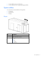
Power
Item
Component
1
Chilled water supply connection
2
Chilled water return connection
3
External communication box (if fitted)
•
•
•
•
ECS
Fire
Security
Telephone
Site requirements
5
Item
Component
1
Main input power junction boxes
2
IT cable portals
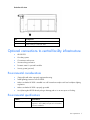
Drainage
Site requirements
6
Drain hot aisle view
Item
Component
1
Water main supply/return drains
2
Heat exchanger condensate drain
Optional connections to central facility infrastructure
•
HP POD ECS
•
Life safety systems
•
Convenience outlet power
•
Site networking connection
•
Domestic water for optional humidifier
•
Security system (optional)
Environmental considerations
•
(Optional) Install under a properly engineered awning.
•
Install lightning protection for the HP POD.
•
Make sure that the HP POD is installed in a well lit area that complies with local workplace lighting
regulations.
•
Make sure that the HP POD is properly grounded.
•
Avoid placing the HP POD directly along a drainage path or in an area prone to flooding.
Environmental specifications
Features
Operating temperature
Specifications
-18ºC to 54ºC (-0ºF to 130ºF).
Supports to -29ºC (-20ºF) with optional cold weather
protection installation.
Site requirements
7
Features
Specifications
Nonoperating
temperature*
-29ºC to 54ºC (-20ºF to 130ºF)
Operating humidity
•
0% to 100% relative noncondensing
Nonoperating humidity*
•
•
5 to 95% relative noncondensing
39ºC (102ºF) maximum wet bulb temperature
Operating altitude
-76.2 to 3,048 m (-250 to 10,000 ft)
Non-operating altitude
-76.2 to 9,144 m (-250 to 30,000 ft)
*For nonoperating specifications, consider the temperature of computer and IT equipment inside the HP POD.
The HP POD must be drained before it is moved to a new location.
For areas prone to freezing, take appropriate water freeze protection precautions.
Lightning protection
If the HP POD is installed in an outdoor environment, then HP recommends hiring a lightning protection
consultant to evaluate potential lightning risks and assess possible HP HP POD lightning protection
schemes.
Site requirements
8
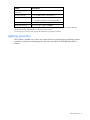
HP POD specifications
Dimensions
The HP POD is approximately 6.7 m (22 ft) long, 2.4 m (8 ft) wide, and 3.1 m (10 ft) tall.
Weight
HP POD weight varies, depending on whether the HP POD is empty or configured with IT equipment.
Computer racks and IT equipment add incremental weight to an empty HP POD and vary, depending on
customization.
Specification
Approximate weight
Empty HP POD
7,727 kg (17,000 lb)
Maximum weight of IT
equipment for each rack
1,364 kg (3,000 lb)
Maximum weight of IT
equipment for each HP POD
13,640 kg (30,000 lb)
Fully outfitted HP POD
22,500 kg (49,500 lb)
IMPORTANT: Before moving the HP POD to a new location, HP recommends contacting the
local Department of Transportation for permit loads and other transportation requirements.
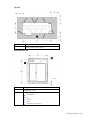
Required clearances
NOTE: Shaded areas indicate required clearances.
HP POD specifications 9
Top view
Item
Component
1
Heat exchanger access panels
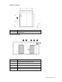
Water input side view
Item
Component
1
CWR/CWS portal
2
Central facility infrastructure connection:
•
•
•
•
•
HP POD ECS
Fire
Security
Phone
Convenience outlet power
HP POD specifications 10
Double door end view
Item
Component
1
IT cable portals
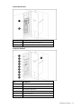
External cold aisle view
Item
Component
1
Fire suppression and humidifier cabinet
2
EPO button
3
Controlled access keypad (optional)
4
Entry door
5
EPO strobe light
HP POD specifications 11
External hot aisle view
Callout
Feature
1
Main input power A and B feeds
2
Controlled access keypad (optional)
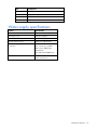
Internal components
The actual location of various components or subsystems in your HP POD might vary from this
documentation. For final placement specifications, see your operations and maintenance manual.
Item
Component
1
EPO controls and indicators
HP POD specifications
12
Control cabinet interior
Item
Component
1
Access control system components
2
Fire alarm/fire suppression system components
Component backwall
Item
Component
1
ASSD
2
EPO
3
Transformers and meters
4
ECS/PLC/IO components
5
Power monitoring
6
Current transducers
HP POD specifications 13
Item
Component
7
Fan sequencers
8
Fan power relays
9
Redundant power relays
10
EPO controls and indicators
Water supply specifications
Feature
Specification
Facility input temperature to HP POD
12º to 24ºC (55º to 75ºF)
Working pressure
1034 kPa (150 psi)
HP POD pressure drop
1732 kPa (25 psi)
HP POD water flow rate
454 l/min (120 gal/min)
Cooling water supply and return
connections
North America:
Two 7.62 cm (3 in.) ASME
B16.5 class 150# flanges
International:
Two DIN PN16 DN80 flanges
Humidifier
See the humidifier manual for
exact requirements
HP POD specifications 14
Water quality requirements
Water quality requirements and specifications
•
Closed-loop water must not contain any lime scale deposits or loose debris.
•
The chilled water temperature to be supplied to the HP POD must be 12º to 24ºC (55º to 75ºF).
NOTE: Freezing water might cause a blockage and damage to the unit. In outside locations
subject to freezing temperatures, an additive such as glycol might be necessary to lower the
freezing point. However, since the heat transfer potential of water with glycol is lower, the HP
POD must be derated accordingly.
NOTE: The water cycle must be drained completely, and then purged using compressed air
when storing or transporting at or below freezing temperatures.
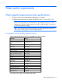
Acceptable water quality specifications
Water must be maintained per the following acceptable water quality standards.
Parameter
Range
pH
8.0–10
Specific conductance at 25ºC
(77ºF)
0–2500 µmhos/cm
Alkalinity ("M" as CaCO3)
150–1000 ppm
Sulfur (SO4)
0–150 ppm
Chloride (Cl)
0–100 ppm
Hardness (CaCO3)
0–350 ppm
Calcium hardness (CaCO3)
0–200 ppm
Magnesium hardness (CaCO3)
0–150 ppm
Copper (Cu)
< 0.20 ppm
Iron (Fe)
< 3.0 ppm
Aluminum (Al)
< 0.50 ppm
Sodium (Na)
0–1000 ppm
Silica (SiO2)
0–150 ppm
Zinc (Zn)
< 1.0 ppm
Manganese (Mn)
< 0.1 ppm
Phosphate Ortho- (PO4)
< 3 ppm
Bacteria
< 1000 CFU/ml
Suspended solids
< 10 ppm
If your water is out of range, consult a water quality expert.
Water quality requirements
15
Piping materials
Do not use the following interconnecting piping materials in a closed water system:
•
Oxidizing biocides
•
Aluminum components
•
Brass components with high levels of zinc
•
Non-stainless steel iron components
Water precautions
Take the following precautions before installation of the HP POD:
•
Verify that all foreign matter and particulates are flushed from the system. Water might be discolored
during the initial flushing of the system. Clear running water is the sign that all foreign matter and
particulates have been flushed from the system.
•
Evaluate the short-term and long-term system requirements against the available water capacity.
•
Ensure that the chilled water loop is properly designed for liquid cooling systems and is separate
from the sanitary water systems in your building (bathroom, sink, drinking water).
•
Ensure facility managers are aware of the additional load being added to the chilled water supply of
the building. Be aware that the added heat load might affect other components being cooled by the
chilled water plant.
Condensation management
CAUTION: During operation, avoid leaving the HP POD doors open, to maintain accurate
environmental conditions inside the HP POD.
Supply cooling water that is above the dew point inside the HP POD to prevent condensation forming on
the heat exchangers.
The heat exchanger drip tray will collect any condensation that forms on the heat exchangers. This
collected condensate drains out of the HP POD through the heat exchanger condensate drains. HP
recommends connecting condensate drains on the HP POD to a facility drain to prevent collection of
water near the HP POD.
There is one heat exchanger condensate drain outlet located near the bottom of the HP POD in between
the access doors on the hot aisle side. There are three drains for the water main supply and return lines
located near the bottom of the HP POD on the cold aisle side.
To avoid excessive buildup of condensate and to conserve energy, raise the cooling water temperature to
above the dew point to manage condensation while maintaining the necessary cooling capacity.
Water quality requirements
16
Power management
Connection requirements
When determining the final location of your power and water connections, consider the distance between
the facility utilities and the HP POD.
The facility power connection must be installed in compliance with local electrical codes and regulations.
HP can provide engineering services to develop the site installation plan and drawings as a supplemental
service.
Power requirements
The HP POD is available in North American and International models. Both models provide 145 kW
redundant or 290 kW non redundant power for the critical load.
•
The North American HP POD includes step-down isolation transformers and requires two 400A,
480V, 3-phase delta feeds at 50-60 Hz.
•
The International HP POD does not require transformers and requires two 400A, 380-415V, 3-phase
wye feeds at 50-60 Hz. All 3-phase HP POD feeders require that the neutrals and the equipment
grounding conductors remain isolated. Bonding of the two conductors is allowed at the power
source only.
For higher density loads that require more power capacity, both 400A inputs can be fed from the same
source. When a lower density critical load is used, N+N redundancy can be accomplished by connecting
the two 400A feeds to independent sources.
Main input power
Power management
17
Item
Component
1
Main input power side B lugs and breakers, located
behind dead front panels.
2
Main input power side A lugs and breakers, located
behind dead front panels.
3
Landing/penetration portal B for attaching incoming
conduit connections for the main input
4
Landing/penetration portal A for attaching incoming
conduit connections for the main input
Main input power details
Power management
18
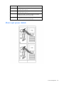
Supported facility connections
Humidifier specifications
A dedicated supply of domestic water is required if the optional humidifier is installed. For exact
requirements for the humidifier model that was installed, see the humidifier manual supplied with the HP
POD.
Item
Component
1
Humidifier drain
2
Water supply
For more information about the humidifier, see the documentation developed by the humidifier
manufacturer.
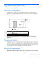
Convenience outlets
The HP POD is prewired for a convenience outlet on the inside of the unit. This circuit is not part of the
power provided by the main switchboard feeding the 3-phase power to the HP POD. To energize this
circuit, you must supply a dedicated single phase, 16-or 20-amp branch circuit from your facility at the
appropriate voltage. Make sure that the branch circuit is connected to the prewired exterior mounted
junction box and must be wired in accordance with local regulations and codes.
Grounding requirements
The neutrals and equipment grounding conductors for all 3-phase HP POD feeders must remain isolated.
The two conductors can be bonded at the power source only.
Supported facility connections 19
Functional and supplementary grounding straps are provided between each rack and HP POD.
IMPORTANT: Before installing the HP POD, consult your local AHJ for applicable codes and
to review site-specific location guidelines.
IMPORTANT: You must ground the HP POD to your ground grid system for full protection.
IT cable portals
Six 63.5-mm (2 ½-inch) IT cable portals on the double door end of the HP POD are available for optional
Ethernet, fiber optic, and IT cable configuration. These components are also used for optional ECS
configuration and can support dedicated lines, a customer network, and various other communications
service options. You may install a weatherproof box for termination points on the outside of the HP POD
over the cable portals.
Examples of cables that can run into the 63.5 mm (2 ½ inch) portals are as follows:
•
48 Cat-6 cables
•
39 12 strand multi-mode or single-mode fiber optic cables
HP POD security
The HP POD is equipped with standard key lock hardware at each entry door and external panel.
Conduit and junction boxes are provided for customer-installed controlled access systems.
Optional controlled access security includes a 12 digit security code keypad and magnetic locks on all
entry doors.
HP POD Environmental Control System
The HP POD ECS is a stand-alone system and does not require any connections to existing facility
management infrastructure. You can choose to connect to the facility BMS at additional cost. BMS
configuration communicates through an Ethernet cable connected to the internal HP POD ECS panel jack
located inside the junction box. HP POD ECS data can be sent and viewed to a set IP address.
The HP POD ECS communicates through Modbus TCP protocol. Modbus TCP is a data communication
protocol for building automation and control networks.
The ECS offers:
•
The ability to monitor status of water and air temperatures, water pressures, and water flow rates
•
Immediate notification of all supported alarm messages
•
Real-time power consumption
For additional points that can be monitored, see the I/O (Input/Output) Controls Points List.
Supported facility connections 20
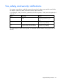
Fire, safety, and security notifications
Dry contacts are provided to enable the connection between the fire alarm system and the central facility
fire detection system, relay alarm, and trouble conditions at each HP POD.
Your building fire, safety, and security system relays the following alarms, which operate independently of
each other.
Alarm
Meaning
Solution
Smoke alarm
Smoke has been detected in the HP
POD.
Activate the EPO. Follow standard
emergency procedures for your
facility.
Security
A security breach has occurred.
Follow standard emergency
procedures for your facility.
EPO
Someone has activated the EPO
system and shut down the HP POD.
Follow standard emergency
procedures for your facility.
The electrical layout of the fire alarm system is as described in the schematic drawing supplied with the
HP POD.
Supported facility connections 21
Acronyms and abbreviations
ASSD
air sampling smoke detector
BMS
building management system
ECS
environmental control system
EPO
emergency power off
POD
Performance-Optimized Datacenter
TVSS
Transient Voltage Surge Suppression
Acronyms and abbreviations
22