1
HP Advanced Power Manager
User Guide
Abstract
This guide provides installation and operation guidance for the HP Advanced Power Manager. This guide is for the person who installs, administers,
and troubleshoots servers and storage systems.
Part Number: 747697-001
June 2014
Edition: 1
© Copyright 2014 Hewlett-Packard Development Company, L.P.
The information contained herein is subject to change without notice. The only warranties for HP products and services are set forth in the express
warranty statements accompanying such products and services. Nothing herein should be construed as constituting an additional warranty. HP shall
not be liable for technical or editorial errors or omissions contained herein.
Confidential computer software. Valid license from HP required for possession, use or copying. Consistent with FAR 12.211 and 12.212,
Commercial Computer Software, Computer Software Documentation, and Technical Data for Commercial Items are licensed to the U.S. Government
under vendor’s standard commercial license.
Contents
Introduction .................................................................................................................................. 8
HP APM overview ........................................................................................................................................ 8
HP APM kit contents ........................................................................................................................... 9
HP APM front view ........................................................................................................................... 10
HP APM rear view ............................................................................................................................ 11
HP APM connections ........................................................................................................................ 11
HP SL Advanced Power Manager Distribution Module ......................................................................... 14
HP Intelligent Modular PDU Managed Extension Bar ............................................................................ 15
Using RJ-45 connections.................................................................................................................... 16
Naming and numbering conventions .................................................................................................. 16
Rack chassis numbering .................................................................................................................... 17
Automatic discovery ......................................................................................................................... 18
Installation and configuration ....................................................................................................... 20
Prerequisites for installation ......................................................................................................................... 20
Preparing for installation ............................................................................................................................. 20
Configuring the HP APM for the first time ...................................................................................................... 20
Configuring the HP APM ............................................................................................................................. 20
Serial port configuration ................................................................................................................... 22
Network configuration ...................................................................................................................... 22
Duplicating the configuration ....................................................................................................................... 23
Command Line Interface .............................................................................................................. 24
Command line conventions ......................................................................................................................... 24
Accessing the HP APM command line interface ............................................................................................. 24
Accessing the HP APM through SSH................................................................................................... 24
Accessing the HP APM through Telnet ................................................................................................ 24
Accessing the HP APM through the serial port ..................................................................................... 25
Saving configurations ................................................................................................................................. 25
Topology and inventory .............................................................................................................................. 25
Showing the rack ............................................................................................................................. 25
Showing the servers ......................................................................................................................... 28
Showing topology ............................................................................................................................ 28
Showing assetinfo ............................................................................................................................ 29
Showing the MAC address ............................................................................................................... 30
Logging ..................................................................................................................................... 32
Overview of logging .................................................................................................................................. 32
Internal logging.......................................................................................................................................... 32
Showing and clearing the event log ................................................................................................... 32
Showing and clearing the fault log..................................................................................................... 35
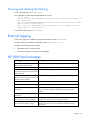
External logging ......................................................................................................................................... 35
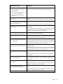
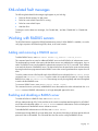
HP APM fault messages .............................................................................................................................. 35
XML-related fault messages.......................................................................................................................... 37
Working with RADIUS servers ..................................................................................................................... 37
Adding and removing a RADIUS server .............................................................................................. 37
Enabling and disabling a RADIUS server ............................................................................................ 37
Contents
3
Showing a RADIUS server ................................................................................................................. 38
Power capping ........................................................................................................................... 39
Power capping overview............................................................................................................................. 39
Power capping requirements ....................................................................................................................... 39
Power capping and measurement tolerance .................................................................................................. 39
Invalidating a power baseline ..................................................................................................................... 39
Power capping licensing ............................................................................................................................. 40
HP APM and HP APM Distribution Module cabling ........................................................................................ 40
Rack level power capping ........................................................................................................................... 40
Power baseline ................................................................................................................................ 41
Setting power capping ..................................................................................................................... 43
Power commands ....................................................................................................................................... 49
Displaying the rack power status........................................................................................................ 50
Setting power .................................................................................................................................. 51
Polling servers for power values ......................................................................................................... 52
Disabling the polling of servers for power values ................................................................................. 53
General commands ..................................................................................................................... 54
Working with passwords ............................................................................................................................ 54
Setting HP APM passwords ............................................................................................................... 54
Disabling HP APM passwords ........................................................................................................... 55
Changing HP APM passwords ........................................................................................................... 55
Resetting factory settings for HP APM ................................................................................................. 55
Working with accounts ............................................................................................................................... 55
Adding an account........................................................................................................................... 55
Removing an account ....................................................................................................................... 56
Showing accounts ............................................................................................................................ 56
Working with zones ................................................................................................................................... 56
Adding zones .................................................................................................................................. 56
Removing zones ............................................................................................................................... 58
Showing zones ................................................................................................................................ 58
Saving zones ................................................................................................................................... 58
Using password recovery ............................................................................................................................ 58
Showing configurations .............................................................................................................................. 59
Using the help............................................................................................................................................ 59
Setting the name ........................................................................................................................................ 59
Setting the time .......................................................................................................................................... 60
Setting the session timeout ........................................................................................................................... 60
Setting the UID LED..................................................................................................................................... 60
Showing information .................................................................................................................................. 60
Showing the name ..................................................................................................................................... 61
Showing the time ....................................................................................................................................... 61
Showing the version ................................................................................................................................... 61
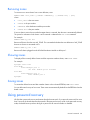
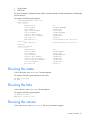
Rebooting and resetting factory settings ........................................................................................................ 62
Rebooting the HP Moonshot 1500 Chassis CM module ................................................................................. 62
Performing a reset ...................................................................................................................................... 62
Performing a reset buddy ............................................................................................................................ 62
Clearing the screen .................................................................................................................................... 62
Resetting factory settings ............................................................................................................................. 62
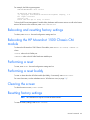
Exiting, logging out, or quitting HP APM....................................................................................................... 63
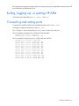
Connecting and setting ports ....................................................................................................................... 63
Using SNMP .............................................................................................................................. 64
Contents
4
SNMP overview ......................................................................................................................................... 64
Enabling SNMP ......................................................................................................................................... 64
Displaying SNMP parameters ...................................................................................................................... 64
Setting the SNMP read-only community string................................................................................................ 65
Setting the SNMP read-write community string............................................................................................... 65
Setting the SNMP contact ............................................................................................................................ 65
Setting the SNMP location........................................................................................................................... 65
Setting SNMP trap destinations.................................................................................................................... 65
SNMP support of cpqHoSwRunningTable ..................................................................................................... 66
Using XML ................................................................................................................................. 67
XML overview ............................................................................................................................................ 67
XML headers.................................................................................................................................... 67
XML output ...................................................................................................................................... 67
Data types ....................................................................................................................................... 67
Response definitions ......................................................................................................................... 68
Enabling XML ............................................................................................................................................ 69
Showing and resetting keys ......................................................................................................................... 69
Logging in through XML .............................................................................................................................. 69
Modifying the user account ......................................................................................................................... 69
Requesting information with XML commands ................................................................................................. 70
Requesting firmware version .............................................................................................................. 70
Requesting rack topology .................................................................................................................. 70
Requesting rack information .............................................................................................................. 70
Modifying compute node power .................................................................................................................. 70
Requesting compute power node status ........................................................................................................ 71
Resetting HP APM ...................................................................................................................................... 71
Firmware ................................................................................................................................... 73
Upgrading the firmware.............................................................................................................................. 73
Troubleshooting .......................................................................................................................... 74
Alert messages ........................................................................................................................................... 74
Devices not discovered ............................................................................................................................... 74
CLI commands ............................................................................................................................ 75
Clear faults ................................................................................................................................................ 75
Clear log ................................................................................................................................................... 75
Clear screen .............................................................................................................................................. 75
Disable Ethernet ......................................................................................................................................... 75
Enable Ethernet .......................................................................................................................................... 75
Disable telnet ............................................................................................................................................. 76
Enable telnet .............................................................................................................................................. 76
Disable SSH .............................................................................................................................................. 76
Enable SSH ............................................................................................................................................... 76
Remove account ......................................................................................................................................... 76
Add account .............................................................................................................................................. 76
Disable password....................................................................................................................................... 77
Enable password ....................................................................................................................................... 77
Set password account ................................................................................................................................. 77
Ping .......................................................................................................................................................... 78
Exit ........................................................................................................................................................... 78
Help ......................................................................................................................................................... 79
Logout ....................................................................................................................................................... 79
Quit .......................................................................................................................................................... 79
Contents
5
Reset ......................................................................................................................................................... 79
Reset buddy ............................................................................................................................................... 79
Reboot ...................................................................................................................................................... 79
Reboot CM ................................................................................................................................................ 80
Reset factory .............................................................................................................................................. 80
Save ......................................................................................................................................................... 80
Save config ............................................................................................................................................... 80
Set IP ........................................................................................................................................................ 81
Set gateway .............................................................................................................................................. 81
Set name ................................................................................................................................................... 81
Set power.................................................................................................................................................. 81
Set serial ................................................................................................................................................... 82
Set syslog .................................................................................................................................................. 82
Set time ..................................................................................................................................................... 82
Set timeout ................................................................................................................................................ 82
Set power baseline ..................................................................................................................................... 83
Set power cap ........................................................................................................................................... 83
Set asset info ............................................................................................................................................. 83
Show accounts ........................................................................................................................................... 84
Show config .............................................................................................................................................. 84
Show faults ................................................................................................................................................ 84
Show info .................................................................................................................................................. 84
Show log................................................................................................................................................... 84
Show syslog .............................................................................................................................................. 84
Show name ............................................................................................................................................... 85
Show power .............................................................................................................................................. 85
Show rack ................................................................................................................................................. 85
Show servers ............................................................................................................................................. 86
Show topology .......................................................................................................................................... 86
Show asset info .......................................................................................................................................... 86
Show MAC address ................................................................................................................................... 87
Show time ................................................................................................................................................. 87
Show power baseline ................................................................................................................................. 87
Show version ............................................................................................................................................. 87
Upgrade image ......................................................................................................................................... 87
Add zone .................................................................................................................................................. 88
Save zones ................................................................................................................................................ 89
Show zones ............................................................................................................................................... 89
Remove zone ............................................................................................................................................. 89
Enable pollpower ....................................................................................................................................... 89
Disable pollpower ...................................................................................................................................... 89
Enable SNMP ............................................................................................................................................ 90
Disable SNMP ........................................................................................................................................... 90
Show SNMP .............................................................................................................................................. 90
Set SNMP RO ............................................................................................................................................ 90
Set SNMP RW ........................................................................................................................................... 90
Set SNMP contact ...................................................................................................................................... 91
Set SNMP location ..................................................................................................................................... 91
Set SNMP trapdest ..................................................................................................................................... 91
Enable XML ............................................................................................................................................... 92
Enable XML secure ..................................................................................................................................... 92
Disable XML .............................................................................................................................................. 92
Show keys ................................................................................................................................................. 92
Contents
6
Reset keys ................................................................................................................................................. 92
Add RADIUS server .................................................................................................................................... 93
Enable RADIUS .......................................................................................................................................... 93
Disable RADIUS ......................................................................................................................................... 93
Remove RADIUS server ............................................................................................................................... 93
Show RADIUS ............................................................................................................................................ 93
Set RADIUS pollnum ................................................................................................................................... 93
Set RADIUS pollsec..................................................................................................................................... 94
Enable NTP ............................................................................................................................................... 94
Set NTP server ........................................................................................................................................... 94
Set NTP poll .............................................................................................................................................. 94
Show NTP server ........................................................................................................................................ 94
Show NTP poll ........................................................................................................................................... 95
Disable NTP .............................................................................................................................................. 95
Connect port.............................................................................................................................................. 95
Set port ..................................................................................................................................................... 95
XML commands .......................................................................................................................... 96
Login ........................................................................................................................................................ 96
Modify user ............................................................................................................................................... 96
Get firmware version .................................................................................................................................. 96
Get rack topology ...................................................................................................................................... 97
Get rack information .................................................................................................................................. 97
Modify compute node power ...................................................................................................................... 97
Modify all compute node power .................................................................................................................. 98
Get compute node...................................................................................................................................... 98
Get all compute node power ....................................................................................................................... 99
Reset HP APM ............................................................................................................................................ 99
Supported MIB objects .............................................................................................................. 100
Supported cpqRack MIB objects ................................................................................................................ 100
Supported cpqHostOs MIB objects ............................................................................................................. 103
Supported rfc1213 MIB objects ................................................................................................................. 103
PDU identity table .................................................................................................................................... 109
PDU input table ........................................................................................................................................ 109
Regulatory information .............................................................................................................. 110
Safety and regulatory compliance .............................................................................................................. 110
Belarus Kazakhstan Russia marking............................................................................................................ 110
Turkey RoHS material content declaration ................................................................................................... 111
Ukraine RoHS material content declaration ................................................................................................. 111
Warranty information ............................................................................................................................... 111
Support and other resources ...................................................................................................... 112
Before you contact HP .............................................................................................................................. 112
HP contact information .............................................................................................................................. 112
Acronyms and abbreviations ...................................................................................................... 113
Documentation feedback ........................................................................................................... 114
Index ....................................................................................................................................... 115
Contents
7
Introduction
HP APM overview
HP APM is a rack-level point of contact for HP ProLiant Scalable System and HP Apollo administration. For a
full description of HP APM features and support, see the Quick Specs on the HP website
(http://h18000.www1.hp.com/products/quickspecs/14189_div/14189_div.pdf).
HP APM enables:
•
Discovery of server rack components by topology
•
Node-level power monitoring and control
•
Support of logging through standard syslog servers
•
Support for power capping at the rack level
NOTE: The use of the term server represents nodes, server trays, server nodes, and cartridges.
SL APM has been replaced by HP APM. Though there is shared functionality, the two products should be
treated as mutually exclusive. The content included in this document is specific to HP APM, and is not
applicable to SL APM.
•
For more information on SL APM support, see the HP ProLiant SL Advanced Power Manager User Guide
on the HP website (http://www.hp.com/support/SLAPM_UG_en).
•
For more information on HP APM support, see the HP Advanced Power Manager User Guide on the HP
website (http://www.hp.com/support/APM_UG_en).
Introduction
8
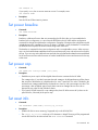
HP APM kit contents
Item
Description
1
HP APM
2
Mounting brackets (2)
3
Terminal blocks (2)
4
Power cords (2)
5
Bracket mounting screws, T-20 (2)*
6
Rack mounting screws, 10-32 (2)*
7
Cage nuts (2)*
8
This document*
*Not shown
The following cables are required to connect the HP APM to the system:
•
Consolidated Management cable
•
Micro DB9 to DB9 cable or Micro DB9 to Micro DB9 cable
•
Ethernet cable
All cables are sold separately.
Introduction
9
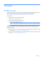
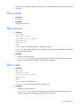
HP APM front view
Item
Description
1
Consolidated Management Ports 1 through 10 (RDM1)
2
Power LED
3
Serial management for top of rack switch
4
RDM3 port for HP APM distribution module
5
RDM2 port for HP APM distribution module
6
iLO port
7
UID
8
Health LED
9
Reset button
10
Ethernet Management port
11
Service port
12
Serial console port
13
Micro SD slot
14
Power Distribution Module ports
NOTE: HP recommends configuring the HP APM so that it controls only one rack.
HP APM has six power distribution ports on the front of the unit. The HP APM has two RDM ports, and each
RDM port has 10 connections to SL Scalable System enclosures.
Introduction
10
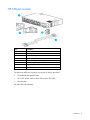
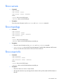
HP APM rear view
Item
Description
1
Power plugs 1 and 2
2
On-Generator and AUX signals
3
Redundant reset
HP APM connections
HP APM offers new rack level management solutions that consolidate IT control, monitoring, and console
access to hosted server, storage, fabric, and power resources to a single wire at the chassis level.
•
10 Consolidated Management Ports, which include ethernet, serial, and hardware signaling ports,
connect to each SL chassis mounted rack.
•
Six Power Distribution Module ports are used to interface directly to rack mounted power feed
infrastructure.
•
The Redundant Reset port is used to connects to another HP APM module (Buddy).
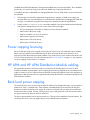
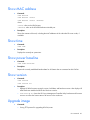
The following figure shows the HP APM unit connected to 10 unique chassis through the Consolidated
Management Ports (RDM1). While RDM connectors are provided for backwards compatibility with existing
HP ProLiant SL servers, connecting through the Consolidated Management Ports is the preferred wiring
solution for new SL servers.
Introduction
11
Depending on the product being connected to the HP APM, the HP APM connects to the system components
using various cables. All cables required for connecting the HP APM to the system must be purchased
separately.
Item Component
Connects To
1
HP Apollo a6000 Chassis
2
HP Apollo 6000 Power Shelf The Power Distribution Module ports on
the HP APM
The RDM1 connector on the HP APM
3
HP APM
—
4
Power Distribution Unit
The Power Distribution Module ports on
the HP APM
5
HP ProLiant SL Series Chassis Server port on the RDM
6
HP ProLiant SL Series Chassis Server port on the RDM
7
HP Moonshot 1500 Chassis
Server port on the RDM
8
HP Intelligent Modular PDU
Managed Extension Bar
The Power Distribution Module ports on
the HP APM
9
Production network
Ethernet port on the HP APM
Introduction
12
Item Component
Connects To
10
Terminal
Serial console port on the HP APM
11
RDM
•
•
RDM2 or RDM3 port on the HP APM
RDM/HP APM* port on the product
chassis
*Some products may identify this as the SL APM port.
NOTE: HP APM considers the10 Consolidated Management Ports as RDM1.
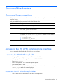
Required connections
Connection
Required cables
HP APM to chassis
Consolidated Management cables
HP APM to power device*
Micro DB9 to DB9 cable or Micro DB9 to
Micro DB9 cable
HP APM to management and
production networks
Ethernet cable
HP APM to RDM
RJ-45 cable included with the RDM
RDM to chassis
These cables are attached to the RDM.
*Power devices include a power shelf, power distribution unit, HP Intelligent Extension Bar, or other power devices, if
installed.
Identifying the RDM1 ports
For products using HP APM, connect the chassis to one of the corresponding consolidated management ports
(RDM1) on the HP APM module.
Introduction
13
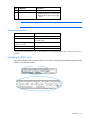
Identifying the RDM2 and RDM3 ports
Consolidated management ports (RDM1) are used only for products designed to work with HP APM when a
separate RDM is not required. When connecting the HP APM module to an RDM, always use either the
RDM2 or RDM3 ports.
Item
Description
1
RDM2 port
2
RDM3 port
HP SL Advanced Power Manager Distribution Module
The distribution module includes a connector bay for the HP APM and cables for SL Scalable Series servers.
It is backwards compatible with SL APM. The following servers and chassis require the use of the distribution
module:
•
HP Moonshot System
•
HP ProLiant SL2500 Scalable System
•
HP ProLiant SL4500 Server Series
•
HP ProLiant SL6500 Scalable System
For more information, see the HP website (http://www.hp.com/go/scalable).
Introduction
14
Item
Description
1
Connector port to the RDM2 or RDM3 ports on HP APM
2
SL Scalable Series server connectors
3
Power (green) LED, which indicates connection to port
4
Activity (amber) LED, which indicates activity to HP APM Distribution Module
The HP Apollo a6000 Chassis connects directly to the Consolidated Management Ports (RDM1). For more
information, see "Naming and numbering conventions (on page 16)."
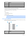
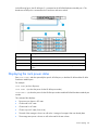
HP Intelligent Modular PDU Managed Extension Bar
The extension bar provides power management for external devices. The extension bar, when used with the
HP cable part number SF672A and HP APM, is not intended for power management of SL enclosures.
The total rating of the Intelligent Extension Bar is 16 A.
Callout
Description
1
Row of green power indicators (one for each outlet)
2
Row of blue UID indicators (one for each outlet)
3
2.4-m (8-ft) input power cord
4
Five managed 10 A, IEC-320 C13 outlets
5
Blue UID indicator for the Intelligent Extension Bar
6
Green power indicator for the Intelligent Extension Bar
7
Reset button*
*When you press the Reset button, power to the managed outlets is maintained. Management functionality is
momentarily lost while the Intelligent Extension Bar resets.
Introduction
15
Using RJ-45 connections
You can have one HP APM per power network (one CLI interface over an Ethernet). One HP APM can
connect up to two HP APM Rack Distribution Modules. Each SL APM Rack Distribution Module can connect
up to 10 SL chassis with an RJ-45 connection or an 8-pin standard connector that comes with the RDM.
Naming and numbering conventions
The following figure shows an example of the basic HP APM configuration and node numbering convention
on a scalable system enclosure. The SL APM Distribution Module allows you to extend the functionality of the
HP APM to more than one server. For more information, see the SL APM Distribution Module ("HP SL
Advanced Power Manager Distribution Module" on page 14).
Item
Description
1
HP Apollo a6000 Chassis
2
HP ProLiant SL Series Chassis
Introduction
16
Item
Description
3
HP ProLiant SL Series Chassis
4
HP Moonshot 1500 Chassis
5
Power Distribution Unit
6
HP Intelligent Modular PDU Managed Extension Bar
7
SL APM Distribution Module
When entering commands that require specific port and node numbers, use the HP APM port number, SL
APM Distribution Module port number, and the SL server node number.
For example, to turn on the power for SL server node 3 that is connected to SL APM Distribution Module port
4, which is connected to HP APM port 2, enter the following:
SET POWER ON 2 4 3
where:
2 is the HP APM port.
4 is the SL APM Distribution Module port.
3 is the SL server node.
Parameters must have spaces between them.
NOTE: HP APM considers the10 Consolidated Management Ports as RDM1.
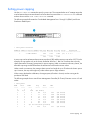
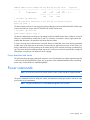
Rack chassis numbering
If you must number the chassis in your rack or data center, then HP APM can display the chassis numbering,
based on the HP APM Distribution Module port connection.
Item
Description
1
HP APM Distribution Module
2
HP APM connection
Introduction
17
Item
Description
3
Connections to SL series enclosures
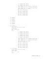
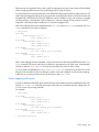
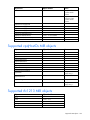
The HP APM commands SHOW TOPOLOGY and SHOW RACK displays the SL chassis connected with number,
based on the HP APM port connection.
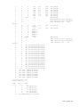
For example:
SHOW TOPOLOGY
1: SL enclosure
Product Name :HP ProLiant SL6500
Product SKU :
Serial Number:
UID :off
Status :
1 : Compute node (active)
2 : Compute node (active)
3 : Compute node (active)
4 : Compute node (active)
5 : Compute node (active)
6 : Compute node (active)
7 : Compute node (active)
8 : Compute node (active)
2: SL enclosure
Product Name :HP ProLiant SL6500
Product SKU :
Serial Number:
UID :off
Status :
1 : Compute node (active)
2 : Compute node (active)
**
**
3: SL enclosure
Product Name :HP ProLiant SL6500
Product SKU :
Serial Number:
UID :off
Status :
1 : Compute node (active)
****
Automatic discovery
HP APM employs an automatic discovery process that identifies all SL series servers in the attached
enclosures.
Introduction
18
The discovery process also has a simple fault detection mechanism. If any node has faults detected (for
example, power supply failure), the discovery response data reports the fault. For a list of alert messages, see
"Alert messages (on page 74)".
Introduction
19
Installation and configuration
Prerequisites for installation
The HP APM can be administered through the serial console. Initial configuration requires a serial terminal
set to 115200.
Preparing for installation
1.
If you are not using a DHCP server, have your necessary IP address information available that will be
used to access the HP APM.
2.
Secure a serial terminal, which is required for the initial setup of the HP APM.
3.
To use a remote logging server, verify that a remote syslog server and the IP address for connecting to
the remote syslog server are available.
Installation guidelines:
•
The HP APM can be installed in the front of the rack or in the rear of the rack. Always install the HP APM
with the connectors facing the outside of the rack.
•
If a top-of-the-rack switch is installed, HP recommends that you install the HP APM behind the top of the
rack switch.
For more information on installing the HP APM, see the HP Advanced Power Manager Installation Instructions
that accompany the option kit or see the HP website (http://www.hp.com/go/Apollo_6000/docs).
Configuring the HP APM for the first time
Both the serial and Ethernet devices on the HP APM provide access to the CLI. The CLI is the only mechanism
provided for HP APM administration.
HP APM must be configured before SSH and Telnet administration is made available. Initial configuration of
the HP APM requires a terminal set to 115200 bits/s, no parity, 8 data bits, and one stop bit (“115200 N
8 1”).
Configuring the HP APM
When you boot up, a LOGIN prompt appears. Enter Administrator as the user account:
Login: Administrator
You can initially configure the HP APM in the following ways:
•
Enter CONFIG to use the simplified configuration wizard. The wizard provides you with a step-by-step
process for configuring HP APM. This procedure is for new users.
•
Enter the commands manually. This procedure is for advanced users who want more control over the
configuration process.
Installation and configuration 20
•
Duplicate the configuration. For more information, see "Duplicating the configuration (on page 23)."
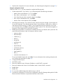
Using the configuration wizard
When you enter CONFIG, you are prompted to complete the following tasks.
1.
Set the onboard clockIf you select Y, you will be prompted for the following information:
o
MonthEnter a value between 1 to 12. Press Enter.
o
DayEnter a value between 1 to 31. Press Enter.
o
YearEnter the year (value must be four digits). Press Enter.
o
HourEnter a value between 0-23. Press Enter.
o
MinutesEnter a value between 0-59. Press Enter.
2.
Name the power managerIf you select Y, enter a name for the power manager. System names can
be up to 80 characters. It can include uppercase letters, lowercase letters, underscores (_), dashes (-),
and numerical values between 0-9. Dashes (-) are not supported as the first character. To save the
power manager name, press Enter. Naming the HP APM is optional. This is the name that appears in
log entries on the syslog server as well as the CLI prompt.
3.
Enable password protectionHP APM has no default password. If you select Y, enter a password. The
password must be between 8 and 40 characters, and can include:
o
uppercase letters
o
lowercase letters
o
underscores (_)
o
dashes (-)
o
at signs (@)
o
pound signs (#)
o
carets (^)
o
ampersands (&)
o
exclamation points (!)
o
plus symbols (+)
o
equal symbols (=)
o
tilde (~)
o
numerical values between 0–9
To save and enable the password, press Enter. For more information about working with passwords,
see "Working with passwords (on page 54)."
4.
Configure the Ethernet port.
5.
Use DHCP or static.
6.
Enter an IP address if static. If the static IP address is invalid, DHCP is assumed.
7.
Enter an IP address mask if static. If the IP address mask is invalid, DHCP is assumed.
8.
Enable Telnet.
9.
Enable SSH.
10.
To review the enabled configuration before saving it, select Y.
11.
Save the new configuration. To save the new configuration, select Y. All settings relating to the HP APM
Ethernet and serial interfaces are persistent and stored in the HP APM.
Installation and configuration 21
Serial port configuration
Verify that the client matches the following settings:
•
Baud rate115200
•
Data bits8
•
Stop bits1
•
ParityNone
•
Flow controlNone
To set a different serial baud rate, enter SET SERIAL <BAUD_RATE>, where <BAUD_RATE> is the baud
rate setting to be used.
You must reboot before baud rate takes effect. You must change the settings on your client to match the
settings on the HP APM.
Network configuration
The HP APM enclosure has two MAC address labels, one for each slot. The MAC address is slot-specific. You
might need the MAC address when you configure the DHCP server to access HP APM. To view the MAC
address, enter SHOW INFO. For more information, see "Showing configurations (on page 59)."
Setting a static IP address
To set a static IP address and subnet mask, enter SET IP <ip_address> <subnet_mask>, where
<ip_address> is the IP address and <subnet_mask> is the subnet mask.
To return to DHCP, enter SET IP DHCP.
Setting the network default gateway
To set the network default gateway enter SET GATEWAY <ip_address>, where <ip_address> is the IP
address. HP APM always uses the IP address, subnet mask, and default gateway.
To clear the gateway, enter SET GATEWAY NONE.
Showing the IP address
To show the IP address, enter SHOW IP. The following information appears:
•
IP Address appears in x.x.x.x format
•
IP Mask appears in x.x.x.x format
•
Gateway appears in x.x.x.x format
Verifying network communication
To verify the network communication is working, enter PING <IP address>, where <IP address> is the
IP address you want to test.
Installation and configuration 22
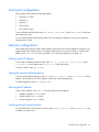
Security configuration
The network interface is disabled when password protection is removed. For more information about
passwords, see "Working with passwords (on page 54)".
Protocol configuration
HP APM supports SSH and Telnet.
Working with SSH configuration
To enable SSH access, enter ENABLE SSH.
To disable SSH access, enter DISABLE SSH.
Working with the Telnet configuration
To enable Telnet access, enter ENABLE TELNET.
To disable Telnet, enter DISABLE TELNET.
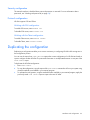
Duplicating the configuration
Duplicating a configuration enables you to ensure consistency in configuring HP APM while saving time in
the configuration process.
You can use the output from SHOW CONFIG to capture the current configuration of a HP APM and used as
input to configure another HP APM. The password information is not duplicated because it is not part of the
SHOW CONFIG output.
To duplicate the HP APM configuration:
1.
Enter SHOW CONFIG.
2.
To copy the configuration, copy the output of the SHOW CONFIG command to a file on your system using
whatever methods are available in your terminal program.
3.
To replicate the configuration, using the methods that are available in your terminal program, apply the
previously saved SHOW CONFIG output as input to the new HP APM.
Installation and configuration 23
Command Line Interface
Command line conventions
CLI input is case insensitive except when otherwise noted. The CLI uses a simple, case insensitive verb noun
"<target>" syntax.
Each command follows the conventions listed in the following table.
Symbol
Description
<lower case>
Denotes the variable within the symbols that must be substituted with a value, such as
a user name. Symbols must be removed.
UPPER CASE
Denotes input to be entered as shown.
Unless noted, symbol is not case-sensitive.
|
Used to separate input options.
{ }
Denotes a list of mandatory choices that you must make.
For example, SET GATEWAY {NONE | <ip_address>} must be in the form of either
of the following:
•
•
SET GATEWAY NONE
SET GATEWAY <ip_address>
[ ]
Denotes an optional argument or set of characters.
" "
Encloses command arguments that contain spaces.
Accessing the HP APM command line interface
You can access the HP APM through SSH, Telnet, or the serial port.
Accessing the HP APM through SSH
1.
Using any SSH client application, start a SSH session to HP APM.
2.
When prompted, enter the assigned IP address or FQDN of HP APM.
3.
Enter Administrator.
4.
Enter a valid password. The CLI command prompt appears.
5.
Enter commands for HP APM.
6.
To terminate the remote access SSH session, close the communication software or enter EXIT,
LOGOUT, or QUIT at the CLI command prompt.
Accessing the HP APM through Telnet
1.
Start a Telnet session to HP APM using any Telnet client application.
Command Line Interface
24
2.
When prompted, enter the assigned IP address or FQDN name of HP APM.
3.
Enter Administrator.
4.
Enter a valid password. The CLI command prompt appears.
5.
Enter commands for HP APM.
6.
To terminate the remote access Telnet session, close the communication software or enter EXIT,
LOGOUT, or QUIT at the CLI command prompt.
Accessing the HP APM through the serial port
You can also access the HP APM through the serial port. For more information, see "Serial Port Configuration
(on page 22)."
Saving configurations
You must save your configurations. Otherwise, the configuration will be lost when you reset or reboot the HP
APM.
To save a configuration, enter SAVE.
Topology and inventory
HP APM collects information from connected enclosures, including:
•
SL enclosure product names
•
SL enclosure product identifiers (SKU)
•
SL enclosure serial numbers
•
Node MAC addresses
To show this information using the previous configuration image as an example, use any of the following
commands.
Showing the rack
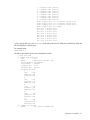
To show the contents of the rack, enter SHOW RACK. The rack information appears, including the product
name, product SKU, and product serial number of the chassis.
For example, the following text might appear:
APM-D4C9EFCB01CA> show rack
1: Display ports
1: SL enclosure
Product Name :HP ProLiant s6700
Product SKU :
Serial Number:
UID
:off
Status
:
1 : Compute node
2 : Compute node
3 : Compute node
4 : Compute node
5 : Compute node
(active)
(active)
(active)
(active)
(active)
Command Line Interface
25
6 : Compute node (active)
7 : Compute node (active)
8 : Compute node (active)
Power supply slot 1 is occupied, status good
Power supply slot 2 is occupied, status good
Power supply slot 3 is occupied, status good
Power supply slot 4 is empty
Fan slot 1 status good
Fan slot 2 status good
Fan slot 3 status good
Fan slot 4 status good
Fan slot 5 status good
Fan slot 6 status good
Fan slot 7 status good
Fan slot 8 status good
2:
3:
4:
5:
6:
7:
8:
9:
10:
(vacant)
(vacant)
(vacant)
(vacant)
(vacant)
(vacant)
(vacant)
(vacant)
(vacant)
2: Dist. Module
1: SL enclosure
Product Name :HP ProLiant s6500
Product SKU :
Serial Number:
UID
:off
Status
:
1 : Compute node (active)
2 : Compute node (active)
3 : Compute node (active)
4 : Compute node (active)
5 : Compute node (active)
6 : Compute node (active)
7 : Compute node (active)
8 : Compute node (active)
Power supply slot 1 is occupied, status good
Power supply slot 2 is occupied, status good
Power supply slot 3 is occupied, status good
Power supply slot 4 is empty
Fan slot 1 status good
Fan slot 2 status good
Fan slot 3 status good
Fan slot 4 status good
Fan slot 5 status good
Fan slot 6 status good
Fan slot 7 status good
Fan slot 8 status good
2: SL enclosure
Product Name :HP ProLiant s6500
Product SKU :
Serial Number:
UID
:off
Status
:
Command Line Interface
26
1 : Compute node (active)
2 : Compute node (active)
3 : Compute node (active)
4 : Compute node (active)
5 : Compute node (active)
6 : Compute node (active)
7 : Compute node (active)
8 : Compute node (active)
Power supply slot 1 is occupied, status good
Power supply slot 2 is occupied, status good
Power supply slot 3 is occupied, status good
Power supply slot 4 is empty
Fan slot 1 status good
Fan slot 2 status good
Fan slot 3 status good
Fan slot 4 status good
Fan slot 5 status good
Fan slot 6 status good
Fan slot 7 status good
Fan slot 8 status good
To show a particular rack, enter SHOW RACK, followed by either the HP APM port or both the HP APM and
HP APM Distribution Module ports.
For example, enter:
SHOW RACK 2 4
The following example uses the power distribution module:
> show rack pdm
9: [PDM1] PDM Extension
UID
: off
Model
: Monitored PDU Ext. Bar
Serial Number: 2CJ9410002
Part Number : AF529A
Firmware Rev : 0.35
Hardware Rev : HW_PV2
Switched Outlets:
1:
UID
: off
Enabled: yes
Wattage: 092
2:
UID
: off
Enabled: yes
Wattage: 139
3:
UID
: off
Enabled: yes
Wattage: 011
4:
UID
: off
Enabled: yes
Wattage: 219
5:
UID
: off
Enabled: yes
Wattage: 050
10: [PDM2] HP 60A PDU
Model
: STI Serial TrueRMS PDU
Command Line Interface
27
Serial Number: ADFV0000083
Asset Tag
: SCI Lab PDU
Part Number : QL192A
Firmware Rev : 1.0a
Switched Outlets:
1: enabled
2: enabled
3: enabled
4: enabled
5: enabled
6: enabled
Input Feeds:
1:
Amps Drawn
: 0.840000
Infeed Status
: On
Infeed Load Status : Normal
2:
Amps Drawn
: 0.860000
Infeed Status
: On
Infeed Load Status : Normal
3:
Amps Drawn
: 0.800000
Infeed Status
: On
Infeed Load Status : Normal
4:
Amps Drawn
: 2.530000
Infeed Status
: N/A
Infeed Load Status : Normal
This command produces the same results as the SHOW SERVERS and SHOW TOPOLOGY commands.
If you must number the chassis in your rack or data center, then HP APM can display the chassis numbering,
based on the HP Advanced Power Manager Distribution Module port connection. For more information, see
"Rack Chassis Numbering (on page 17)."
To show all the chassis and other devices connected to the HP APM, enter SHOW RACK ALL.
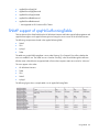
Showing the servers
To show the servers, enter SHOW SERVERS. The server information appears.
This command produces the same results as the SHOW RACK and SHOW TOPOLOGY commands.
Showing topology
To show the topology of everything that connects to the HP APM, enter SHOW TOPOLOGY. The topology
appears.
This command produces the same results as the SHOW RACK and SHOW SERVERS commands.
If you must number the chassis in your rack or data center, then HP APM can display the chassis numbering,
based on the HP APM Distribution Module port connection. For more information, see "Rack Chassis
Numbering (on page 17)."
To show all the chassis and other devices connected to the HP APM, enter SHOW TOPOLOGY ALL.
Command Line Interface
28
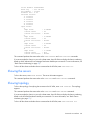
Showing assetinfo
To list all the chassis in the rack in a report format, enter SHOW ASSETINFO.
For example, the following text might appear:
slapm> show assetinfo 1 7
1: Dist. Module
7: SL enclosure
Product Name :HP ProLiant s6500
Product SKU :629235-B21
Serial Number:USE119A2MM
UID
:off
Status
:
1 : Compute node (active) Asset tag: myserver1
Serial #: USE119A2YW
2 : Compute node (active) Asset tag: myserver2
Serial #: USE119A2YT
3 : Compute node (active) Asset tag: myserver3
Serial #: USE119A319
4 : Compute node (active) Asset tag: myserver4
Serial #: USE119A31C
5 : Compute node (active) Asset tag: myserver5
Serial #: USE119A2N8
6 : Compute node (active) Asset tag: myserver6
Serial #: USE119A2N3
7 : Compute node (active) Asset tag: myserver7
Serial #: USE119A2N4
8 : Compute node (active) Asset tag: myserver8
Serial #: USE121AJYH
Power supply slot 1 is occupied, status good
Power supply slot 2 is occupied, status good
Power supply slot 3 is occupied, status good
Power supply slot 4 is occupied, status good
Fan slot 1 status good
Fan slot 2 status good
Fan slot 3 status good
Fan slot 4 status good
Fan slot 5 status good
Fan slot 6 status good
Fan slot 7 status good
Fan slot 8 status good
This command also requests and shows any asset tags from the chassis and any 30- or 60-amp PDUs that are
in the rack.
The asset tag information for 30- or 60-amp PDUs can be set through the SET ASSETINFO command.
For example, the following text might appear:
> show assetinfo pdm2
10: [PDM2] HP 60A PDU
Model
: STI Serial TrueRMS PDU
Serial Number: ADFV0000083
Asset Tag
: SCI Lab PDU
Part Number : QL192A
Firmware Rev : 1.0a
Switched Outlets:
1: enabled
Command Line Interface
29
2: enabled
3: enabled
4: enabled
5: enabled
6: enabled
Input Feeds:
1:
Amps Drawn
Infeed Status
Infeed Load Status
2:
Amps Drawn
Infeed Status
Infeed Load Status
3:
Amps Drawn
Infeed Status
Infeed Load Status
4:
Amps Drawn
Infeed Status
Infeed Load Status
: 0.860000
: On
: Normal
: 0.870000
: On
: Normal
: 0.830000
: On
: Normal
: 2.590000
: On
: Normal
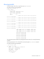
Showing the MAC address
To show the MAC address, enter SHOW MACADDR. The MAC address appears. The MAC address
information appears following each module listing.
For example, the following text might appear on screen.
HP APM> show macaddr
1: Dist. Module
1: SL enclosure
Product Name :HP ProLiant s6500
Product SKU :
Serial Number:
UID
:off
Status
:
1 : Compute node (active) Host MAC: D8:D3:85:AE:E7:03
2 : Compute node (active) Host MAC: 78:E7:D1:E4:6E:1F
3 : Compute node (active) Host MAC: 78:E7:D1:E4:6E:B9
4 : Compute node (active) Host MAC: 78:E7:D1:E4:6E:BD
5 : Compute node (active) Host MAC: D4:85:64:6A:52:2D
6 : Compute node (active) Host MAC: 1C:C1:DE:18:AC:F7
7 : Compute node (active) Host MAC: D4:85:64:6A:51:C3
8 : Compute node (active) Host MAC: D4:85:64:6A:52:6D
Power supply slot 1 is occupied, status good
Power supply slot 2 is occupied, status good
Power supply slot 3 is occupied, status good
Power supply slot 4 is occupied, status good
Fan slot 1 status good
Fan slot 2 status good
Fan slot 3 status good
Fan slot 4 status good
Fan slot 5 status good
Fan slot 6 status good
Command Line Interface
30
Fan slot 7 status good
Fan slot 8 status good
To show a particular MAC address, enter SHOW MACADDR and then the HP APM port or both the HP APM
port and HP APM Distribution Module port.
For example, enter:
SHOW MACADDR 2 4
Command Line Interface
31
Logging
Overview of logging
Logging enables you to see the following information in HP APM:
•
Actions taken
•
Events
•
Time when the action was taken or event occurred
HP APM has the following types of logs:
•
Event logs, where HP APM records events
•
Fault logs, where HP APM records internal errors. These internal errors create alerts in which the red LED
illuminates. For a list of alert messages, see "Alert messages (on page 74)."
You can issue commands for both internal and external logging.
Use an external syslog server for:
•
Redundant copy of events and logs
•
Not limiting the events list to only the last 500 events
To ensure the correct time stamping in your logs, use the SET TIME command. For more information, see
"Setting the time (on page 60)."
Internal logging
Internal logging tracks up to 100KB on the event log, up to 16KB on the fault log, and is persistent through
reboot.
Showing and clearing the event log
To show the event log, enter SHOW LOG.
As an example, the following text might appear
> show log
Nov 6 11:51:25 SLAPM system.0:
port 3, slot 2
Nov 6 11:51:25 SLAPM system.0:
port 3, slot 3
Nov 6 11:51:25 SLAPM system.0:
port 3, slot 4
Nov 6 11:51:25 SLAPM system.0:
port 3, slot 5
Nov 6 11:51:25 SLAPM system.0:
port 3, slot 6
Nov 6 11:51:25 SLAPM system.0:
port 3, slot 7
on screen:
Server found in chassis at Dist. Module #2,
Server found in chassis at Dist. Module #2,
Server found in chassis at Dist. Module #2,
Server found in chassis at Dist. Module #2,
Server found in chassis at Dist. Module #2,
Server found in chassis at Dist. Module #2,
Logging
32
Nov 6 11:51:25 SLAPM system.0: Server found in chassis at Dist. Module #2,
port 3, slot 8
Nov 6 11:51:25 SLAPM system.0: Power supply found in chassis at Dist. Module
#2, port 3, slot 1
Nov 6 11:51:25 SLAPM system.0: Power supply found in chassis at Dist. Module
#2, port 3, slot 2
Nov 6 11:51:25 SLAPM system.0: Power supply found in chassis at Dist. Module
#2, port 3, slot 3
Nov 6 11:51:25 SLAPM system.0: Power supply in chassis at Dist. Module #2,
port 3, slot 1 status is good
Nov 6 11:51:25 SLAPM system.0: Power supply in chassis at Dist. Module #2,
port 3, slot 2 status is good
Nov 6 11:51:25 SLAPM system.0: Power supply in chassis at Dist. Module #2,
port 3, slot 3 status is good
Nov 6 11:51:25 SLAPM system.0: Fan found in chassis at Dist. Module #2, port
3, slot 1
Nov 6 11:51:25 SLAPM system.0: Fan found in chassis at Dist. Module #2, port
3, slot 2
Nov 6 11:51:25 SLAPM system.0: Fan found in chassis at Dist. Module #2, port
3, slot 3
Nov 6 11:51:25 SLAPM system.0: Fan found in chassis at Dist. Module #2, port
3, slot 4
Nov 6 11:51:25 SLAPM system.0: Fan found in chassis at Dist. Module #2, port
3, slot 5
Nov 6 11:51:25 SLAPM system.0: Fan found in chassis at Dist. Module #2, port
3, slot 6
Nov 6 11:51:25 SLAPM system.0: Fan found in chassis at Dist. Module #2, port
3, slot 7
Nov 6 11:51:25 SLAPM system.0: Fan found in chassis at Dist. Module #2, port
3, slot 8
Nov 6 11:51:25 SLAPM system.0: Fan in chassis at Dist. Module #2, port 3,
slot 1 status is OK
Nov 6 11:51:25 SLAPM system.0: Fan in chassis at Dist. Module #2, port 3,
slot 2 status is OK
Nov 6 11:51:25 SLAPM system.0: Fan in chassis at Dist. Module #2, port 3,
slot 3 status is OK
Nov 6 11:51:25 SLAPM system.0: Fan in chassis at Dist. Module #2, port 3,
slot 4 status is OK
Nov 6 11:51:25 SLAPM system.0: Fan in chassis at Dist. Module #2, port 3,
slot 5 status is OK
Nov 6 11:51:25 SLAPM system.0: Fan in chassis at Dist. Module #2, port 3,
slot 6 status is OK
Nov 6 11:51:25 SLAPM system.0: Fan in chassis at Dist. Module #2, port 3,
slot 7 status is OK
Nov 6 11:51:25 SLAPM system.0: Fan in chassis at Dist. Module #2, port 3,
slot 8 status is OK
Nov 6 11:51:26 SLAPM system.0: Server found in chassis at Dist. Module #2,
port 6, slot 1
Nov 6 11:51:26 SLAPM system.0: Server found in chassis at Dist. Module #2,
port 6, slot 2
Nov 6 11:51:26 SLAPM system.0: Server found in chassis at Dist. Module #2,
port 6, slot 3
Nov 6 11:51:26 SLAPM system.0: Server found in chassis at Dist. Module #2,
port 6, slot 4
Nov 6 11:51:26 SLAPM system.0: Server found in chassis at Dist. Module #2,
port 6, slot 5
Nov 6 11:51:26 SLAPM system.0: Server found in chassis at Dist. Module #2,
port 6, slot 6
Logging
33
Nov 6 11:51:26 SLAPM system.0: Server found in chassis at Dist. Module #2,
port 6, slot 7
Nov 6 11:51:26 SLAPM system.0: Server found in chassis at Dist. Module #2,
port 6, slot 8
Nov 6 11:51:26 SLAPM system.0: Power supply found in chassis at Dist. Module
#2, port 6, slot 1
Nov 6 11:51:26 SLAPM system.0: Power supply found in chassis at Dist. Module
#2, port 6, slot 2
Nov 6 11:51:26 SLAPM system.0: Power supply found in chassis at Dist. Module
#2, port 6, slot 3
Nov 6 11:51:26 SLAPM system.0: Power supply in chassis at Dist. Module #2,
port 6, slot 1 status is good
Nov 6 11:51:26 SLAPM system.0: Power supply in chassis at Dist. Module #2,
port 6, slot 2 status is good
Nov 6 11:51:26 SLAPM system.0: Power supply in chassis at Dist. Module #2,
port 6, slot 3 status is good
Nov 6 11:51:26 SLAPM system.0: Fan found in chassis at Dist. Module #2, port
6, slot 1
Nov 6 11:51:26 SLAPM system.0: Fan found in chassis at Dist. Module #2, port
6, slot 2
Nov 6 11:51:26 SLAPM system.0: Fan found in chassis at Dist. Module #2, port
6, slot 3
Nov 6 11:51:26 SLAPM system.0: Fan found in chassis at Dist. Module #2, port
6, slot 4
Nov 6 11:51:26 SLAPM system.0: Fan found in chassis at Dist. Module #2, port
6, slot 5
Nov 6 11:51:26 SLAPM system.0: Fan found in chassis at Dist. Module #2, port
6, slot 6
Nov 6 11:51:26 SLAPM system.0: Fan found in chassis at Dist. Module #2, port
6, slot 7
Nov 6 11:51:26 SLAPM system.0: Fan found in chassis at Dist. Module #2, port
6, slot 8
Nov 6 11:51:26 SLAPM system.0: Fan in chassis at Dist. Module #2, port 6,
slot 1 status is OK
Nov 6 11:51:26 SLAPM system.0: Fan in chassis at Dist. Module #2, port 6,
slot 2 status is OK
Nov 6 11:51:26 SLAPM system.0: Fan in chassis at Dist. Module #2, port 6,
slot 3 status is OK
Nov 6 11:51:26 SLAPM system.0: Fan in chassis at Dist. Module #2, port 6,
slot 4 status is OK
Nov 6 11:51:26 SLAPM system.0: Fan in chassis at Dist. Module #2, port 6,
slot 5 status is OK
Nov 6 11:51:26 SLAPM system.0: Fan in chassis at Dist. Module #2, port 6,
slot 6 status is OK
Nov 6 11:51:26 SLAPM system.0: Fan in chassis at Dist. Module #2, port 6,
slot 7 status is OK
Nov 6 11:51:26 SLAPM system.0: Fan in chassis at Dist. Module #2, port 6,
slot 8 status is OK
Nov 6 11:51:27 SLAPM system: Local user Administrator logged in
Nov 6 07:46:51 SLAPM Administrator: Ethernet interface enabled
Nov 6 07:47:00 SLAPM Administrator: Telnet interface enabled
Nov 6 07:47:00 SLAPM Administrator: ssh interface enabled
Nov 6 07:47:05 SLAPM Administrator: Configuration was saved
To clear the event log, enter CLEAR LOG.
Logging
34
Showing and clearing the fault log
To show the fault log, enter SHOW FAULTS.
As an example, the following text might appear on screen:
> show faults
May 4 19:43:43 APM-D4C9EFCB01CA system.0: Power Manager Power Supply 1 is
non operational
May 5 01:42:20 APM-D4C9EFCB01CA system.0: Timeout waiting for Dist. Module
mutex on Power Manager port 3
May 6 03:51:16 APM-D4C9EFCB01CA system: Failed login attempt with user
'Administrator' from 192.168.1.1
To clear the fault log, enter CLEAR FAULTS.
External logging
To show the syslog server address configuration information, enter SHOW SYSLOG.
To set the syslog server address configuration, enter SET SYSLOG x.x.x.x.
Using an existing syslog server provides:
•
Redundant copy of events and logs
•
No limits to number of events that can be logged
HP APM fault messages
Fault logged message
Description
There was an error transferring the file,
image upgrade not performed
Error occurred during firmware upgrade.
Error upgrading firmware image
Firmware image not upgraded due to an error.
Distribution Module on Power Manager RS-485 port is having excessive errors and has failed.
port X has excessive errors and has been
marked as failed
RS-485 port is having excessive errors and has failed.
Distribution Module port X on Power
Manager port Y has excessive errors and
has been marked as failed
Transmit failed to write
Hardware error transmitting a packet.
Read error on UART
Hardware error receiving a packet.
Power Manager Power supply 1 is non
operational
Power supply in slot 1 is not supplying power to the HP APM chassis.
There is a 20 second delay in detecting a power supply status
change.
Power Manager Power supply 2 is non
operational
Power supply in slot 2 is not supplying power to the HP APM chassis.
Firmware update to Distribution Module, While upgrading the firmware on a Power Manager Distribution
Module, an error occurred. Retry being attempted.
port X failed, retry Y being attempted
Firmware update to Distribution Module, While upgrading the firmware on a Power Manager Distribution
Module, too many errors occurred and the operation has been
port X - all retries, failed, giving up
terminated.
Logging
35
Fault logged message
Description
Fans:
Fans failed or removed.
There is a 20 second delay in detecting a fan status change.
•
•
•
•
•
Power Manager Fan 2, failed
Both fans failed
One or more Fan rotor(s) failed
One or more Fan(s) failed
One or more Fan health status
improved
User config corruption detected, using
backup copy.
The user configuration is corrupted, and HP APM is using the backup
copy.
Remove all accounts, and then add a new account and password.
User config settings lost due to corruption, The user configuration is corrupted, and the backup is corrupted as
well.
please contact HP support.
Remove all accounts and then add a new account and password.
Baseline config corruption detected, using There was a corruption on baseline config, and HP APM is using the
backup copy.
backup copy.
Use CLI command “Show power baseline” to determine if it’s still the
correct baseline. If it is not, then remove the power cap, and if
needed, use CLI command “Set power baseline."
Baseline config settings lost due to
corruption, please contact HP support.
There is no power baseline set.
Use CLI command “Set power baseline."
Key corruption detected, using backup
copy.
There is an key corruption, and HP APM is using the backup copy.
Use CLI command “Disable xml”, if it’s enabled, and shutdown all
SSH sessions. Use CLI command “Reset keys.”
Power cap config corruption detected,
using backup copy.
The power cap is corrupted, and HP APM is using the backup copy.
Use CLI commands “Show power cap” and “Show power baseline”
to verify that the power cap is in the set correctly. If not, use the CLI
command “Set power baseline” and “Set power cap.”
Power cap config settings lost due to
corruption, please contact HP support.
The power cap configuration is corrupted, and the backup is
corrupted as well.
Use CLI commands “Show power cap” and “Show power baseline”
to verify that the power cap is in the set correctly. If not, use the CLI
command “Set power baseline” and “Set power cap.”
Config corruption detected, using backup The configuration is corrupted, and HP APM is using the backup
copy.
copy.
Use CLI command “Config,” or set the individual config item and
save again.
Config settings lost due to corruption,
please contact HP support.
The configuration is corrupted, and the backup is corrupted as well.
Use CLI command “Config,” or set the individual config item and
save again.
Zone config corruption detected, using
backup copy.
The zone configuration is corrupted, and HP APM is using the backup
copy.
Use CLI command “Show zones” and verify if the backup copy is
sufficient. If not, add the zones as needed.
Zone config settings lost due to
corruption, please contact HP support.
The zone configuration is corrupted, and the backup is corrupted as
well.
Use CLI command “Show zones” and verify if the backup copy is
sufficient. If not, add the zones as needed.
Timeout waiting for chassis response.
The chassis failed to respond to the requested command.
Logging
36
XML-related fault messages
The following XML-related fault messages might appear in your fault log:
•
Failed to allocate memory for XML parser.
•
Failed to create a XML Output File for writing.
•
Failed to create a XML Output.
•
XML Rear Error
To attempt to resolve these error messages, first "Disable XML," and then "Enable XML" or "Enable XML
Secure."
Working with RADIUS servers
The HP APM firmware supports the RADIUS authentication protocol. When RADIUS is enabled, it is used to
verify login requests to HP APM through SSH, telnet, or the serial console.
Adding and removing a RADIUS server
To add a RADIUS server, enter ADD RADIUS SERVER <ip_address> <shared_secret>.
This command specifies an initial or additional RADIUS server to the HP APM list of authentication servers.
The authentication proceeds in the same order that these servers were added to the configuration. Up to a
total of five RADIUS servers can be added for authentication purposes. Port 1812 is assumed. The IP address
must match the location of the RADIUS server. The shared secret must be specified in quotes and must match
the string that has been programmed into the RADIUS server when receiving authentication requests from HP
APM.
To set the number of times HP APM polls each of the RADIUS server indicated in the ADD RADIUS SERVER
command, enter SET RADIUS POLLNUM. To set the number of seconds HP APM waits for a reply from the
RADIUS server, enter SET RADIUS POLLSEC. These settings can only be set globally and cannot be applied
to each individual RADIUS server.
To remove a RADIUS server, enter REMOVE RADIUS SERVER <index>.
This command removes a previously added RADIUS server that matches the index indicated with the SHOW
RADIUS command. RADIUS authentication is no longer attempted against this server.
Enabling and disabling a RADIUS server
To enable HP APM as a RADIUS client, enter ENABLE RADIUS.
All login attempts through SSH, Telnet, and the serial console are authenticated through the list of RADIUS
servers that were indicated with the ADD RADIUS SERVER command. Authentication is also verified against
the local password if the RADIUS servers indicate no access.
To disable RADIUS authentication on HP APM, enter DISABLE RADIUS.
Authentication through RADIUS no longer takes place, but password checking is still done against the local
password if that is still enabled. This command does not clear out the configured RADIUS servers.
Logging
37
Showing a RADIUS server
To show the currently configured RADIUS server, enter SHOW RADIUS.
To show the currently configured RADIUS parameter, use the SHOW CONFIG command.
Logging
38
Power capping
Power capping overview
HP Scalable System products, including HP ProLiant SL Series, HP Moonshot Series, and HP Apollo Series
provide a power capping feature that operates at the server enclosure level. The capping feature can be
activated using a stand-alone utility called PPIC.EXE that runs in the environment of one of the resident servers
in the chassis to be power capped. After a power cap is set for the enclosure, all the resident servers in the
enclosure will have the same uniform power cap applied to them until the cap is either modified or canceled.
With HP APM, the enclosure-level power capping feature can be expanded without the need to use the
PPIC.EXE utility. A global power cap can be applied to all enclosures with one HP APM command, or
different caps can be applied to user-defined groups by using flexible zones within the same rack.
NOTE: HP recommends configuring the HP APM so that it controls only one rack.
Power capping requirements
All nodes in the chassis must have iLO Scale Out or iLO Advanced License.
To support the HP APM power capping functionality, all tray nodes in the chassis must be rebooted after the
chassis firmware has been updated, (for the s6500 chassis, the required version is v4.3 or higher) and the
appropriate BIOS version has been flashed. A reboot is also required anytime you add iLO Scale Out or iLO
Advanced License to the node. Upgrading to future versions of chassis firmware or HP APM firmware does
not require a reboot of the node to support the power capping feature.
Power capping and measurement tolerance
The average chassis power level displayed by HP APM will not exceed 5% above the chassis power cap.
NOTE: The power baseline process is required for power capping functionality to work
properly. All servers must be powered on and running an expected typical workload before
starting the power baseline process. Because the baseline process will cap the servers briefly,
performance will be impacted while power is measured and the baseline established.
As with any measurement system, variations in temperature, input power, and system loads will impact the
accuracy of the power calculations. All power reading displayed by this utility will have a -/+ 5% tolerance.
However, meter errors can be both positive and negative, so guardband for meter tolerance, as a
percentage of the cap, can approach zero as the number of servers increases.
Invalidating a power baseline
Since power baselines are global, the HP APM monitors the domains for changes in server and power supply
presence when a power baseline has been established. If a change occurs (for example, if a new server is
Power capping
39
installed), then the HP APM detects this change and invalidates the current power baseline. This invalidation
prevents any new caps from being set, but does not disable any existing caps that are set.
If a baseline has been invalidated due to changing hardware in the HP APM domain, then several options
are available:
•
If the change was caused by replacement of equipment (for example, a failed power supply was
removed and a new one inserted) then you could restore the old baseline by resetting the HP APM and
forcing it to re-read and re-compare the existing power baseline from the resident EEPROM.
•
Always use the SET POWER BASELINE command to establish a new power baseline when the domain
configuration changes because of one or more of the following changes:
o
SL Power Management Controller (SL Chassis) Firmware has been updated.
o
Add or remove the power supply.
o
Install or uninstall a new server or enclosure.
o
Add or remove memory from the tray.
o
Add or remove CPU from the tray.
o
Add or remove GPU from the tray.
Power capping licensing
All servers that are being power capped must have the iLO Scale Out or iLO Advanced License installed.
Before a power baseline can be established, the HP APM verifies that all the servers housed in an SL
enclosure have the advanced license pack installed. If any resident servers in the enclosure do not have the
iLO\LO100 advanced license, the power baseline process ("Power baseline" on page 41), a prerequisite
for power capping for the enclosure, is skipped.
HP APM and HP APM Distribution Module cabling
All supported SL enclosures and servers that are wired to the HP APM through one or more HP APM
Distribution Modules can participate in power capping and monitoring. Separate power cap settings can be
made for as many or as few of the enclosures as desired, but the power baseline process must operate as a
global process that interacts with every supported enclosure that the HP APM is connected to through the HP
APM distribution modules.
Rack level power capping
The rack level power cap is a power cap set at the HP APM level and, despite the name, can encompass a
partial rack, a rack, or multiple racks. These domains are established by the reach of the HP APM and
distribution module connections to the support SL enclosures combined with any optional zone definitions
that may have been created. The term rack level power cap is used generically in this document to refer to
any power cap that has been set at the HP APM level.
The power capping feature has two main processes to it. The first process establishes a power baseline. The
second process sets a power cap against the previously established power baseline.
Power capping
40
Power baseline
The power baseline is a calibration that indicates the range of how little power the chassis can consume at
their maximum allowable power cap and how much power they can consume when completely uncapped.
The minimum value is derived by capping the servers at their maximum internally allowable cap setting,
running the enclosure fans up to 90% of capacity, and then measuring the power consumption of the chassis
at the power supply level.
SL enclosures cannot be power calibrated by the HP APM if:
•
All the servers that populate the chassis do not carry the iLO Scale Out or iLO Advanced license (empty
slots are permitted).
•
The chassis is using incompatible SL Power Management (SL Chassis) enclosure firmware prior to
version 4.3.
•
The server or enclosure hardware does not support the power capping feature.
If these checks are met (HP APM verifies these conditions for each chassis), then the power baseline process
proceeds for that chassis. The baseline calibration process is run against every enclosure connected to the HP
APM with the exceptions listed previously. Some enclosures might be baselined while others are not due to
the previously listed reasons. After a power baseline is established for all enclosures, then the baseline is
committed to the HP APM onboard EEPROM so that it becomes persistent when HP APM is reset during
operation.
NOTE: The power baseline process is required for power capping functionality to work
properly. All servers must be powered on and running an expected typical workload before
starting the power baseline process. Because the baseline process will cap the servers briefly,
performance will be impacted while power is measured and the baseline established.
After established and saved in the EEPROM, the baseline data can be examined at any time using the SHOW
POWER BASELINE command. For example:
> show power baseline
APMPort DMPort Serial Number Min Cap Max Cap Set Cap Slots
Populated
------- ------ ------------- ------- ------- ------- ----- ---------------1
2 CNK71600K4
585
2372
1500
(8)
2 3 5 7
------- ------- ------585
2372
1500
If an HP APM has baseline data in its EEPROM and it is reset, HP APM re-reads that baseline data back into
memory as it boots back up. After the subsequent device discovery, HP APM compares the baseline data in
the EEPROM to the actual rack contents to ensure that they did not change while it was offline or that it was
not relocated to another rack. The HP APM validates the following items from the saved baseline data in these
instances:
•
The chassis listed in the baseline is present.
•
The chassis has the same populated server slots.
•
If a power cap had been set, than it is the power cap currently set on the chassis.
If any of these do not match after a reset, then the HP APM logs an error to the log, indicating the mismatch
in the baseline data, and the baseline data will be invalidated. However, it will not be erased from the
EEPROM to provide you the chance to re-install any chassis or servers that invalidated the baseline data.
Power capping
41
To remove baseline data from the EEPROM, use the SET POWER BASELINE NONE command. After this
command is used, the only way to re-establish a power baseline is to use the SET POWER BASELINE
command.
If a power cap is currently in place, the SET POWER BASELINE NONE command cannot be used. The power
cap must first be removed (SET POWER CAP NONE), then the baseline can be removed.
If a power cap is currently in place and a SET POWER BASELINE command is issued, then any current
power caps are removed in the calibration. New power caps can be established following the calibration
process, assuming the new baseline data is saved to the EEPROM.
The following text is an example output when an advanced license is installed on all chassis:
> set power baseline
Before running a baseline calibration - ensure that
your configuration has all machines turned on and are
running processes that are typical of the type of workload
you expect them to run in a production environment.
This process will briefly impact the performance of the
servers that are being baseline calibrated as well as
temporarily speed up the fans.
Are you sure you wish to set a new power baseline for this system? (Y/N/Q)
-> Yes
Retrieving license information for chassis Power Manager port 1, Dist. Module
port 1
Verifying..done
Baselining power for servers located in chassis Power Manager port 1, Dist.
Module port 1
Calibrating.................done.
Minimum cap value for this chassis is 777
Maximum cap value for this chassis is 3558
The following text is an example output when an advanced license was not installed on four chassis (1 1, 1
6, 1 7, and 1 10).
> set power baseline
Before running a baseline calibration - ensure that
your configuration has all machines turned on and are
running processes that are typical of the type of workload
you expect them to run in a production environment.
This process will briefly impact the performance of the
servers that are being baseline calibrated as well as
temporarily speed up the fans.
Are you sure you wish to set a new power baseline for this system? (Y/N/Q)
-> Yes
Retrieving license information for chassis Power Manager port 1, Dist. Module
port 1
Verifying..done
One or more servers located in chassis at Power Manager port 1, Dist. Module
port 1 is not licensed for the power capping feature.
This chassis will be skipped for baselining purposes.
Note:
All licensed servers should be booted up at least once
so the BIOS/ROM can write the relevant license information
to the chassis controller.
Retrieving license information for chassis Power Manager port 1, Dist. Module
port 2
Verifying..done
Power capping
42
Setting power capping
Use the SET POWER CAP command to specify a power cap. The command takes an AC wattage range that
must be between the minimum and maximum values that were set with the SET POWER BASELINE command
and are shown with the SHOW POWER BASELINE command.
The following example illustrates the Consolidated Management Ports 1 through 10 (RDM1) and Power
Distribution Module ports.
> show power baseline
APMPort DMPort Serial Number Min Cap Max Cap Set Cap Slots
Populated
------- ------ ------------- ------- ------- ------- ----- ---------------1
2 CNK71600K4
585
2372
1500 (8) 2 3 5 7
------- ------- ------585
2372
1500
A power cap can be set between the minimum cap value of 585 and the maximum cap value of 2372. In this
example, the cap applies only to the chassis located at APM Port 1, DM Port 2 because that is the only
chassis that met the necessary prerequisites for power capping. Under circumstances with many chassis, the
allowable cap range would fall between the total minimum and total maximum values.
Under normal circumstances, the average chassis power level might be up to 5% above the chassis power
cap. However, the cap value might vary under extreme power usage situations.
When running the baseline calibration, the target system (all nodes in chassis) must be running at the
production level load.
The following example shows mixed Power Management Controller (SL Chassis) Firmware version 4.3 and
earlier:
> show power
MDM
---1
78
1
1
1
1
1
1
1
1
1
Port
---1
n/a
1
1
1
1
1
1
1
2
3
Node
Avg
Min
Max
---------------1
206
(DC watts)
2
80
n/a
203
3
77
n/a
208
4
77
n/a
206
5
81
n/a
207
6
76
n/a
210
7
82
n/a
225
8
81
n/a
225
(no SL enclosure present)
1
255
n/a
337
(DC
(DC
(DC
(DC
(DC
(DC
(DC
watts)
watts)
watts)
watts)
watts)
watts)
watts)
(DC watts)
Power capping
43
1
1
1
1
1
1
1
1
1
1
1
watts)
1
1
1
1
1
1
1
1
1
1
1
1
watts)
1
1
1
1
1
1
2
2
2
2
2
2
2
2
2
2
3
4
5
6
7
8
3
3
3
3
3
3
3
3
3
3
3
2
3
4
5
6
7
8
Fans
257
242
232
265
259
240
258
20
n/a
n/a
n/a
n/a
n/a
n/a
n/a
340
324
315
351
344
325
346
(DC watts)
(DC watts)
(DC watts)
(DC watts)
(DC watts)
(DC watts)
(DC watts)
(DC watts)
2036 (Chassis total - DC watts)
2151 (Chassis total - AC watts)
2247 (Chassis cap
- AC
4
4
4
4
4
4
4
4
4
4
4
4
1
2
3
4
5
6
7
8
Fans
91
(empty)
115
(empty)
(empty)
(empty)
(empty)
(empty)
14
n/a
188
(DC watts)
n/a
186
(DC watts)
(DC watts)
221 (Chassis total - DC watts)
266 (Chassis total - AC watts)
852 (Chassis cap
- AC
5
(no SL enclosure present)
6
(no SL enclosure present)
7
(no SL enclosure present)
8
(no SL enclosure present)
9
(no SL enclosure present)
10
(no SL enclosure present)
1
(no SL enclosure present)
2
(no SL enclosure present)
3
(no SL enclosure present)
4
(no SL enclosure present)
5
(no SL enclosure present)
6
(no SL enclosure present)
7
(no SL enclosure present)
8
(no SL enclosure present)
9
(no SL enclosure present)
10
(no SL enclosure present)
(no Dist. Module present)
(no Dist. Module present)
(no Dist. Module present)
(no Dist. Module present)
(no Dist. Module present)
(no Dist. Module present)
Total servers = 18
Total chassis = 3
PDM
---1
1
1
1
1
2
Port
Load
------1
86 (AC watts)
2
151 (AC watts)
3
0 (AC watts)
4
470 (AC watts)
5
11 (AC watts)
(no PDM Extension present)
Power capping
44
---718
The following example uses the power distribution module.
> show power pdm
PDM port 1
PDM
---1
1
1
1
1
Port
---1
2
3
4
5
Load
---93
140
11
228
50
---522
(AC
(AC
(AC
(AC
(AC
watts)
watts)
watts)
watts)
watts)
PDM port 2
PDU:
STI Serial TrueRMS PDU
Part Number:
QL192A
Serial Number:
ADFV0000083
Asset tag:
SCI Lab PDU
Firmware rev:
1.0a
Infeed Amps:
60
Number of Infeeds: 4
Switched Outlets: 6
Infeeds:
01: Amps drawn: 0.850000 Status: On Load: Normal
02: Amps drawn: 0.880000 Status: On Load: Normal
03: Amps drawn: 0.820000 Status: On Load: Normal
04: Amps drawn: 2.560000 Status: N/A Load: Normal
Switched ports:
01: Enabled
02: Enabled
03: Enabled
04: Enabled
05: Enabled
06: Enabled
> show power 1 3
MDM
Port
------1
3
1
3
1
3
1
3
1
3
1
3
1
3
1
3
1
3
1
3
1
3
1
3
watts)
Node
---1
2
3
4
5
6
7
8
Fans
Total servers = 8
Total chassis = 1
Total fan wattage
Avg
----254
255
244
233
265
258
238
259
20
=
Min
----n/a
n/a
n/a
n/a
n/a
n/a
n/a
n/a
Max
----337
340
324
315
351
344
325
346
(DC watts)
(DC watts)
(DC watts)
(DC watts)
(DC watts)
(DC watts)
(DC watts)
(DC watts)
(DC watts)
2033 (Chassis total - DC watts)
2148 (Chassis total - AC watts)
2247 (Chassis cap
- AC
20 (DC watts)
Power capping
45
Total system wattage = 2033 (DC watts)
Total system wattage = 2148 (AC watts)
> show power baseline
All values listed are in AC watts
APMPort DMPort Serial Number Min Cap Max Cap Set Cap Slots
Populated
------- ------ ------------- ------- ------- ------- ----- ---------------1
3 0000000000
2242
4744
0 (8) 1 2 3 4 5 6 7 8
1
4
845
4744
0 (8) 1 3
------- ------- ------3087
9488
0
> show power
MDM
Port
------1
1
1
2
1
3
1
3
1
3
1
3
1
3
1
3
1
3
1
3
1
3
1
3
1
3
1
3
watts)
1
4
1
4
1
4
1
4
1
4
1
4
1
4
1
4
1
4
1
4
1
4
1
4
watts)
1
5
1
6
1
7
1
8
1
9
1
10
2
1
2
2
2
3
2
4
2
5
2
6
2
7
2
8
2
9
2
10
Node
Avg
Min
Max
---------------(no SL enclosure present)
(no SL enclosure present)
1
255
n/a
337
2
256
n/a
340
3
245
n/a
324
4
235
n/a
315
5
267
n/a
351
6
263
n/a
344
7
237
n/a
325
8
256
n/a
346
Fans
21
1
2
3
4
5
6
7
8
Fans
(no
(no
(no
(no
(no
(no
(no
(no
(no
(no
(no
(no
(no
(no
(no
(no
92
(empty)
115
(empty)
(empty)
(empty)
(empty)
(empty)
14
SL
SL
SL
SL
SL
SL
SL
SL
SL
SL
SL
SL
SL
SL
SL
SL
enclosure
enclosure
enclosure
enclosure
enclosure
enclosure
enclosure
enclosure
enclosure
enclosure
enclosure
enclosure
enclosure
enclosure
enclosure
enclosure
(DC watts)
(DC watts)
(DC watts)
(DC watts)
(DC watts)
(DC watts)
(DC watts)
(DC watts)
(DC watts)
2042 (Chassis total - DC watts)
2157 (Chassis total - AC watts)
2247 (Chassis cap
- AC
n/a
188
(DC watts)
n/a
186
(DC watts)
(DC watts)
223 (Chassis total - DC watts)
268 (Chassis total - AC watts)
852 (Chassis cap
- AC
present)
present)
present)
present)
present)
present)
present)
present)
present)
present)
present)
present)
present)
present)
present)
present)
Power capping
46
3
4
5
6
7
8
Total
Total
Total
Total
Total
PDM
---1
1
1
1
1
2
(no
(no
(no
(no
(no
(no
Dist.
Dist.
Dist.
Dist.
Dist.
Dist.
Module
Module
Module
Module
Module
Module
present)
present)
present)
present)
present)
present)
servers = 10
chassis = 2
fan wattage
=
35 (DC watts)
system wattage = 2265 (DC watts)
system wattage = 2425 (AC watts)
Port
Load
------1
87 (AC watts)
2
150 (AC watts)
3
0 (AC watts)
4
464 (AC watts)
5
11 (AC watts)
(no PDM Extension present)
---712
In the following example, the cap is set to 1500 AC watts. This information is saved as part of the baseline
data to the onboard HP APM EEPROM.
When multiple chassis are present and a valid rack level cap is given, HP APM:
1.
Computes the total cap as a percentage against the sum of the eligible chassis’ max power values.
2.
For each chassis, multiplies the percentage computed in step 1 against each chassis individual max
power value.
3.
Programs the result into the chassis.
4.
Repeats steps 2-3 for each eligible chassis.
To remove a power cap, use SET POWER CAP NONE. This action removes all power cap settings from all
the servers.
Creating HP APM power mappings
Zones are collections of HP APM enclosures that can be given unique names that can be referred to for power
capping purposes.
Zones provide the HP APM user with the capability of distinguishing groups of enclosures as targets for
power or management operations. When zones are defined, they are strictly a boundary definition that is
kept within the HP APM for its purposes. Zones can be added or removed with the ADD ZONE and REMOVE
ZONE commands.
When the first ADD references a zone name that does not exist, the zone is automatically created and the
indicated ports are populated into the newly created zone. Subsequent ADD ZONE commands that reference
the same zone name cause the specified ports to be added to the existing zone. No limit exists for the number
of ports other than the maximum HP APM supports in hardware that can be added to a zone. Multiple port
listings can be used with a single ADD ZONE command, or multiple ADD ZONE commands can be used with
each command adding new ports to the zone previously defined by the first ADD ZONE command.
To remove zone references to ports, use the REMOVE ZONE command. When the last port is removed from
a zone, the zone is automatically deleted. A zone cannot exist where no ports are assigned to it, and zone
port definitions cannot overlap (that is, the same SL chassis cannot exist in more than one zone).
Power capping
47
Defining zones is an optional function, and is useful for applying power caps to some chassis while excluding
others or applying different power caps to different groups or single SL chassis.
Since HP APM zones are merely definitions of user defined HP APM group boundaries (and by extension any
chassis that are plugged into those ports), they ignore the actual physical presence of enclosures as they are
being defined in the HP APM CLI. Empty HP APM ports can be included in a zone. If an enclosure is plugged
into that port later, it automatically is part of that zone. A reminder message will be printed if a zone is
mapped to a HP APM port that currently has no SL enclosure plugged into it.
After zone mappings have been completed with the ADD ZONE and REMOVE ZONE commands, the SHOW
ZONES command can be used, for example:
> show zones
Zone RED:
Power Manager port 1:
Dist. Module port 1
Zone BLUE:
Power Manager port 1:
Dist. Module port 2
Dist. Module port 3
Zone GREEN:
Power Manager port 2:
all Dist. Module ports included
Zone YELLOW:
Power Manager port 3:
Dist. Module port 1
>
After a zone mapping has been completed, it can be saved to the HP APM onboard EEPROM with the SAVE
ZONES command. This action makes the zone definitions persistent across HP APM resets. It automatically
reloads on reboot. If SAVE ZONES is not used, the zone data is lost if the HP APM is reset.
If a zone needs to be deleted, the REMOVE ZONE <zone name> ALL command can be used. This causes
all ports to be removed from the zone definition, and the zone itself is deleted. As with all zone mapping
modifications, to make it persistent across HP APM resets, enter SAVE ZONES.
Power capping with zones
If zones are defined as described above (and assuming a power baseline has been established for the rack),
then the SET POWER CAP command can accept a zone name as a parameter after the wattage value (or
NONE if a power cap is being removed).
For example:
> show zones
Zone BLUE:
Power Manager port 1:
Dist. Module port 2
Dist. Module port 3
Zone GREEN:
Power Manager port 2:
all Dist. Module ports included
Zone YELLOW:
Power Manager port 3:
Dist. Module port 1
> show power baseline
Power capping
48
APMPort DMPort Serial Number Min Cap Max Cap Set Cap Slots
Populated
------- ------ ------------- ------- ------- ------- ----- ---------------1
1
0
0
0 (8)
1
2 CNK71600K4
585
2372
1500 (8) 2 3 5 7
------- ------- ------585
2372
1500
> set power cap 2000 blue
New cap represents 84 percent of the max cap of eligible entities.
Apply cap (Y/N) ->
The above output sets a power cap only to those chassis that are in the zone defined as BLUE. If all the caps
must be removed from a zone, then SET POWER CAP NONE can be used.
> set power cap none blue
Remove power cap(s)? (Y/N) ->
The above command removes all power cap settings from the HP APM chassis that is resident in on the HP
APM port 1 and distribution module ports 2 and 3, or zone blue. Since there is only a single chassis that
matches that description, the operation only affects that one chassis.
If a cap is set using a zone, then the zone is removed, the cap is unaffected. A new zone may be created that
includes some or all of the ports of the former zone and caps set against the new zone as well. Zones are
strictly a defined set of SL enclosures that can be used to specify which machines are being considered for a
cap. They are a vehicle for enabling multiple caps and/or “exclusion” areas to be created within a single HP
APM domain of enclosures with respect to power capping.
Power baselines and zones
The power baseline cannot be created with respect to a zone. The baseline is a singular separate entity that
is saved into the HP APM EEPROM. Zones can use portions of the established baseline when considering
power caps, but the baseline is established globally.
Power commands
NOTE: You must also have an HP ProLiant s6500 Chassis or later with BIOS support required.
The power commands use the HP APM port number, the distribution module port number, and server node
port number as input parameters.
NOTE: HP APM considers the10 Consolidated Management Ports as RDM1.
Power capping
49
In the following figure, the HP APM port 2 is connected to the HP APM Distribution Module port 4. The
distribution module port is connected to the SL enclosure and server node 8.
Item
Description
1
HP APM
2
HP APM Distribution Module
3
SL series enclosure
4
Bay 4 of a 4U chassis SL6500 Scalable System enclosure with eight 1U half-width
nodes
Displaying the rack power status
Enter SHOW POWER, and then optionally the specific HP APM port, or both the HP APM and the HP APM
Distribution Module ports.
For example:
SHOW POWER (to show all power)
SHOW POWER 2 (to show the power for the HP APM port number)
SHOW POWER 2 4 (to show the power for the HP APM port number and the HP APM Distribution Module port
number
This command also displays:
•
Fan power per chassis in DC watts
•
Chassis total in DC watts
•
Chassis total in AC watts
•
Chassis cap in AC watts (if one is set)
•
The total of the averages is shown as well as the "average of averages" that was already there
•
The average max power is shown as well as the total of the max column
Power capping
50
•
A total count of all the servers and chassis listed
•
Total fan wattage for the listing
•
Total system wattage in DC watts
•
Total system wattage in AC watts
For example, the following text might appear on screen:
MDM
Port
Node
Avg
Min
Max
---------------------1
(no Dist. Module present)
2
1
(no SL enclosure present)
2
2
(no SL enclosure present)
2
3
(no SL enclosure present)
2
4
1
67
n/a
165
(DC watts)
2
4
2
(empty)
2
4
3
64
n/a
242
(DC watts)
2
4
4
(empty)
2
4
5
(empty)
2
4
6
(empty)
2
4
7
0
n/a
72
(DC watts)
2
4
8
37 n/a
86
(DC watts)
2
4
Fans
35
(DC watts)
2
4
203 (Chassis total - DC
watts)
2
4
236 (Chassis total - AC
watts)
2
5
1
(empty)
2
5
2
94
n/a
94
(DC watts)
2
5
3
64
n/a
179
(DC watts)
2
5
4
(empty)
2
5
5
74
n/a
169
(DC watts)
2
5
6
(empty)
2
5
7
0
n/a
0
(DC watts)
2
5
8
(empty)
2
5
Fans
235
(DC watts)
2
5
467 (Chassis total - DC
watts)
2
5
507 (Chassis total - AC
watts)
2
5
1500 (Chassis cap - AC
watts)
2
6
(no SL enclosure present)
2
7
(no SL enclosure present)
2
8
(no SL enclosure present)
2
9
(no SL enclosure present)
2
10
(no SL enclosure present)
3
(no Dist. Module present)
4
(no Dist. Module present)
5
(no Dist. Module present)
6
(no Dist. Module present)
7
(no Dist. Module present)
8
(no Dist. Module present)
Setting power
Power management enables you to turn on and off single or multiple nodes within the rack.
Power capping
51
To turn an SL server node on or off, use the SET POWER command:
SET POWER {ON|OFF|ENABLE|DISABLE} {ALL | <PORT#> <DMPORT#> {<NODE#>|ALL}}
where:
ALL is used when the command applies to all nodes. You can also use ALL when the command applies to
all the server nodes in a particular SL server enclosure.
<PORT#> refers to the HP APM, PDM1, or PDM2 port numbers.
<DMPORT#> refers to the HP APM Distribution Module port number or the HP Intelligent Modular PDU
Extension Bar outlet number.
<NODE#> refers to the SL server node.
For example, to power on SL server node 3, enter:
SET POWER ON 2 4 3
To power off SL server node 3, enter:
SET POWER DISABLE 2 4 3
When you power on a particular SL server enclosure, you must include either the node number or ALL in the
command.
To power on the SL server nodes in the enclosure, enter:
SET POWER ON 2 4 ALL
To power on all nodes connecting to the chassis on all HP APM Distribution Module ports, enter:
SET POWER ON ALL
SNMP traps denoted by an asterisk (*) are not supported on the HP ProLiant s6500 Chassis. The SET POWER
ON ALL and SET POWER OFF ALL commands are not supported on HP APM 1.54 on the HP Moonshot
1500 Chassis.
To power on the PDU ports, enter:
SET POWER ON PDM
To power off PDU ports, enter:
SET POWER OFF PDM
Polling servers for power values
To enable a background process that polls each server for its average, minimum, and maximum power
values, enter ENABLE POLLPOWER.
Polling these values increases the performance of SNMP queries of these power values.
The poll cycle time varies depending on how many server chassis are plugged into the HP APM system. The
more chassis that are present, the less frequently each server will be polled.
If POLLPOWER is enabled, then an SNMP request for any of these values on any resident server returns the
last polled value instead of requesting the real time values from the server at the time the request is made.
Power capping
52
Disabling the polling of servers for power values
To disable the background process that is polling each server for power usage, enter DISABLE
POLLPOWER. The DISABLE POLLPOWER setting is the default.
Power capping
53
General commands
Working with passwords
HP APM has a password recovery mechanism through the reset switch. If you press the reset switch for more
than 5 seconds, the board reboots and proceeds in the password recovery mode. In the password recovery
mode, the board boots up without asking for a password. All network interface is disabled.
HP APM has only one login account. This account is the “Administrator” account. If a password is assigned
to the administrator account, the password is stored on the HP APM controller. If you move the controller to
another HP APM enclosure, the password moves with the controller.
Configuring Ethernet requires a password.
Setting HP APM passwords
To set the password, enter SET PASSWORD.
You are prompted for a password when you access SSH, Telnet, or serial port access to the HP APM. You can
have only one password for HP APM.
The password must be between 8 and 40 characters, and can include:
•
Uppercase letters
•
Lowercase letters
•
Underscores (_)
•
Dashes (-)
•
At signs (@)
•
Pound signs (#)
•
Carets (^)
•
Ampersands (&)
•
Exclamation points (!)
•
Plus symbols (+)
•
Equal symbols (=)
•
Tilde (~)
•
Numerical values between 0–9
To save and enable the password, press Enter.
Alternatively, you can set the password by entering SET PASSWORD <”password”>. For example, enter
the following:
SET PASSWORD "alphabravo"
General commands
54
When entering a password in this manner, you must include quotation marks around the password being set.
This form of command is useful for scripted setup.
Disabling HP APM passwords
To disable the password, enter DISABLE PASSWORD.
This command disables the password protection feature. If the password is disabled, all network interfaces
are also disabled.
Changing HP APM passwords
To change the password of the current user, enter SET PASSWORD "<newpassword>". This command
changes the password of the current user to "<newpassword>".
To change the password of a specific user, enter SET PASSWORD ACCOUNT "<user>"
"<newpassword>". This command changes the password of the "<user>" to a "<newpassword>".
NOTE: Only the Administrator can add or remove an account. You can change your own
password, but only the Administrator can change another user's password.
Resetting factory settings for HP APM
To restore the HP APM to its factory default settings, enter RESET FACTORY.
This command restores HP APM to factory settings, including no password and Ethernet access, and then
performs a reboot.
WARNING: When you enter RESET FACTORY, HP APM erases your entire configuration.
Before resetting factory defaults, consider saving your configuration. For more information on
duplicating your configuration, see "Duplicating the configuration (on page 23)".
NOTE: This command can only be run from the serial console.
Working with accounts
HP APM supports 11 login accounts (including the built-in Administrator account) on a single HP APM board.
The account username must be between 2 to 32 characters. Valid characters are uppercase letters,
lowercase letters, numbers (0-9), underscores (_) and dashes (-).
Adding an account
To add an account, enter ADD ACCOUNT. For example, enter
myslapm> add account "MyLogin123"
Password must be at least 8 characters
Note: password will not show.
Enter account "MyLogin123" password:
Enter account "MyLogin123" password (again):
Saving password..done.
General commands
55
Account MyLogin123 enabled
myslapm>
The account name must be between2-32 characters. If you attempt to use more than 32 characters, you will
receive an error message:
myslapm> add account
"adkfjklsdjflsdjflsjflksdjfkljsdkljfklsdjfkljsdklfjsdljfklsdj"
Account name has invalid character or is reserved
Account name must be 2-32 characters
Valid characters are A-Z,a-z,0-9,_,and -.
After you enter this command with a valid new username, a prompt asking for a password appears. Enter the
password. The new account is available for system login.
If you do not specify a password, and the username does not already exist, then you are prompted for a
password.
All user accounts have the same permissions.
NOTE: Login accounts and passwords are stored separate from the board configuration. A
SHOW CONFIG command will not reveal any ADD ACCOUNT commands.
Removing an account
To remove an account, enter REMOVE ACCOUNT “<username>”
where:
"<username>" is the account username.
This command removes the specified account from the system. If the user does not exist, then an error
message appears.
The Administrator account cannot be deleted.
Showing accounts
To show the existing defined accounts, including the reserved Administrator account, enter SHOW
ACCOUNTS.
For example:
myslapm> show accounts
Administrator
root
myslapm>
Working with zones
HP APM enables the addition, removal, and showing of chassis to a zone, and the saving of zones.
Adding zones
To add one or more chassis to a zone, enter
General commands
56
ADD ZONE <zone_name> [[<PORT#> <DMPORT#>]] | [<PORT#> ALL] | [ALL]
where:
•
<zone_name> is the zone name.
•
<PORT#> is the port number.
•
<DMPORT#> is the distribution module port number.
•
<PORT# ALL> is the port number.
For example:
myslapm> add zone red 1 2
Zone RED does not exist, would you like to create it? (Y/N) -> Yes
Note: there currently is no physical chassis plugged into Power Manager port 1,
Dist. Module port 2
RED zone added
Zone definition changed, do you want to save this data to the EEPROM? (Y/N) ->
No
Note: You can also save zone data to the EEPROM at any time with the SAVE ZONES
command
myslapm>
If the zone does not already exist, then it will be automatically created and the specified chassis will be
added.
You can create up to four zones.
The parameters enable the addition of all chassis on all HP APM ports, all the chassis plugged into an HP
APM port through a HP APM Distribution Module) or a specific chassis on a specified HP APM port and HP
APM Distribution Module port. The syntax is similar to other HP APM commands such as SHOW POWER or
SHOW RACK in how HP APM and HP APM Distribution Module ports are specified.
When adding a chassis to a zone, the chassis does not have to be present and plugged into the HP APM. The
HP APM issues a message in such cases, and therefore, the chassis does not exist. Zone definitions do not
require the hardware to be actually present . For HP APM operations that might use zones (for example, SET
POWER BASELINE), only those chassis that exist and are defined in the zone are considered for the
operation.
For example:
ADD ZONE my_zone 1 5
Adds the chassis plugged into HP APM Distribution Module port 5 on HP APM port 1 to zone MY_ZONE. If
MY_ZONE did not already exist, it will be created.
ADD ZONE my_zone 1 all
Adds all the chassis plugged into an HP APM Distribution Module on HP APM port 1.
ADD ZONE my_zone all
Adds all chassis on the HP APM to zone MY_ZONE.
ADD ZONE BLUE 1 ALL 2 ALL 3 1
You can also use ALL by itself instead of a PORT DMPORT pair.
For example:
ADD ZONE BLUE ALL
Zones cannot overlap.
General commands
57
Removing zones
To remove one or more chassis from a zone definition, enter
REMOVE ZONE <zone_name> [[<PORT#> <DMPORT#>]] | [<PORT#> ALL] | [ALL]
where:
•
<zone_name> is the zone name.
•
<PORT#> is the port number.
•
<DMPORT#> is the distribution module port number.
•
<PORT# ALL> is the port number.
If no more chassis exist in the zone after the target chassis is removed, then the zone is automatically deleted.
The syntax for indication which chassis is to be removed is identical to the ADD ZONE command.
For example:
REMOVE ZONE my_zone ALL
Removes all chassis from the zone MY_ZONE. This command also deletes the zone definition of MY_ZONE
because no chassis is associated with it.
REMOVE ZONE my_zone 1 ALL
Removes all chassis plugged into the HP APM Distribution Module on APM port 1.
Showing zones
To display all the currently defined zones and their respective member chassis, enter SHOW ZONES.
For example:
myslapm> show zones
Zone BLUE:
Power Manager port 1:
all Dist. Module ports included
Zone RED:
Power Manager port 1:
Dist. Module port 2
myslapm>
Saving zones
To commit the defined zones and their member chassis to the on-board EEPROM, enter SAVE ZONES.
You can define and save up to four zones. These zones are automatically loaded from the EEPROM when the
board is reset.
Using password recovery
HP APM has a password recovery mechanism through the reset switch. If you press the reset switch for more
than 5 seconds, the board reboots and proceeds in the password recovery mode. In the password recovery
mode, the board boots up without asking for a password. All network interface is disabled.
General commands
58
Showing configurations
To show the configuration, enter SHOW CONFIG. A list of commands representing the configuration of HP
APM appears.
Using the help
To access the help, enter HELP. The following listing appears:
APM-D4C9EFCB00B4> help
ADD
Add entity
CLEAR
Empty log entries
CLOSE
Close rack's doors
CONFIG
Configure HP APM
CONNECT
Connect board peripherals
CONTROLLER
Rack controller controls
DISABLE
Turn off board features
ENABLE
Turn on board features
EXIT
Exit CLI
HELP
Show help messages
LOGOUT
Exit CLI
OPEN
Open rack's doors
QUIT
Exit CLI
PING
Ping a remote host
REBOOT
Reboot firmware
REMOVE
Remove entity
RESET
Reset HP APM
SAVE
Save HP APM config or zones
SET
Set board configuration
SHOW
Display information
TEST
Test commands
UPGRADE
Pull in new firmware
Each listing has its own listings. For example, when HELP CLEAR is entered, the following appears:
HP APM> help clear
CLEAR
FAULTS
LOG
SCREEN
Empty
Empty
Empty
Clear
log entries
the fault log
system log
the screen
This listing shows the items that you can clear:
•
To empty the fault log, enter CLEAR FAULTS.
•
To empty the system log, enter CLEAR LOG.
•
To clear the screen, enter CLEAR SCREEN.
Setting the name
To set the name that appears in the log and syslog entries, enter SET NAME "<name>". For example:
SET NAME "alphabravo"
System names can be up to 80 characters, and can include uppercase letters, lowercase letters, underscores
(_), dashes (-), and numerical values between 0-9. Dashes (-) are not supported as the first character. To save
General commands
59
the power manager name, press Enter. Naming the HP APM is optional. This is the name that appears in
log entries on the syslog server as well as the CLI prompt.
Setting the time
To set the time, enter SET TIME <month> <day> <year> <hour> <minute>
where:
•
<month> is the month.
•
<day> is the day.
•
<year> is the year.
•
<hour> is the hour, in 24-hour format. For example, enter 3:00 p.m. as 15.
•
<minute> is the minute.
HP APM does not automatically adjust for Daylight Savings Time.
The time remains on this setting until you issue the RESET FACTORY command.
Setting the session timeout
To set the SSH and Telnet inactivity timeout, enter SET TIMEOUT {<timeout_value> | NONE}
where <timeout_value> is the timeout value measured in seconds.
For example, to set a 30-second timeout, enter:
SET TIMEOUT 30
If you specify NONE, then no timeouts are set. For example, enter:
SET TIMEOUT NONE
The timeout values are in increments of 5 seconds. The minimum timeout value is 15 seconds and the
maximum timeout value is 21,600 seconds (6 hours).
Setting the UID LED
To activate the UID LED, enter SET UID ON.
To deactivate the UID LED, enter SET UID OFF.
If there is a parameter specified such as <PORT#> <DMPORT#>, the UID of the chassis is turned on/off.
Showing information
To show information, enter SHOW INFO. The following information appears:
•
Manufacturer
•
Product Name
•
Part Number
•
Spare Part Number
General commands
60
•
Serial Number
•
FRU File ID
The power manager is the bottom board, and the connector module is the top board that has all the display
port connections.
For example, the following text appears:
APM-D4C9EFCB01CA> show info
Power Manager
-----------Manufacturer:
Product Name:
Part Number:
Spare Part Number:
Serial Number:
Chassis Part Number:
Chassis Serial Number:
FRU File Id:
MAC Address 1:
chassis)
MAC Address 2:
chassis)
Connector Module
-----------Manufacturer:
Product Name:
Part Number:
Serial Number:
Chassis Part Number:
Chassis Serial Number:
Power Brick Part Number:
Fan Part Number:
FRU File Id:
HP
HP RACK MANAGER
000000-000
735178-001
1234567890ABCD
730917-001
1234567890
05/29/13
D4:C9:EF:CB:01:CA (stored in
D4:C9:EF:CB:01:00 (stored in
HP
HP APM BOARD
741191-B21
PDUUCX2TM5G00T
739945-001
1234567890
747059-001
747410-001
09/03/13
Showing the name
To show the name, enter SHOW NAME. The name appears.
For example, the following text appears on the screen:
HP APM> show name
HP APM
Showing the time
To show the time, enter SHOW TIME. The time appears.
For example, the following text appears:
HP APM> show time
MON OCT 1 12:56:21 2012
Showing the version
To show the version, enter SHOW VERSION. The version information appears.
General commands
61
For example, the following text appears:
APM-D4C9EFCB00B4> show version
HP Advanced Power Manager
(c) Copyright 2014 Hewlett-Packard Development Company, L.P.
All rights reserved
Version 2.00
Build time was Apr 21 2014, 11:58:04
To show the HP Power Management Controller Utility hardware and firmware versions as well as the license
status of all servers in the enclosures, enter SHOW VERSION ALL.
Rebooting and resetting factory settings
To reboot, enter REBOOT. Unsaved configuration settings are lost.
Rebooting the HP Moonshot 1500 Chassis CM
module
To reboot the HP Moonshot 1500 Chassis CM module, enter REBOOT CM <PORT#> <DMPORT #>.
where:
<PORT#> refers to the HP APM port.
<DMPORT#> refers to the HP APM Distribution Module port.
Performing a reset
To reset, enter RESET. Unsaved configuration settings are lost.
Performing a reset buddy
To reset or reboot the other HP APM module (the Buddy, if connected), enter RESET BUDDY.
For more information, see the redundant reset in "HP APM rear view (on page 11)."
Clearing the screen
To clear the session screen, CLEAR SCREEN.
Resetting factory settings
NOTE: This command can only be run from the serial console.
To reset the factory settings, enter RESET FACTORY.
General commands
62
All configuration and password settings will be lost. Password access will be disabled. Network access will
be prevented due to disabled password.
Exiting, logging out, or quitting HP APM
To exit enter one of the following: EXIT, LOGOUT, enter QUIT.
Connecting and setting ports
To connect the current CLI session to the specified serial port, enter CONNECT PORT.
To configure a single or all serial ports, enter SET PORT.
Ports 1 through 10 refer to the display ports, and 11 and 12 refer to the serial ports.
This is an example of setting port to 115200 baud rate with 8N1:
myslapm> set port 1 115200 8N1
Serial Port 1 set to 115200 bps, 8N1
This is an example of setting all ports to 115200 baud rate with 8N1:
myslapm> set port all 115200 8N1
Serial Port 1 set to 115200 bps, 8N1
Serial Port 2 set to 115200 bps, 8N1
Serial Port 3 set to 115200 bps, 8N1
Serial Port 4 set to 115200 bps, 8N1
Serial Port 5 set to 115200 bps, 8N1
Serial Port 6 set to 115200 bps, 8N1
Serial Port 7 set to 115200 bps, 8N1
Serial Port 8 set to 115200 bps, 8N1
Serial Port 9 set to 115200 bps, 8N1
Serial Port 10 set to 115200 bps, 8N1
Serial Port 11 set to 115200 bps, 8N1
Serial Port 12 set to 115200 bps, 8N1
General commands
63
Using SNMP
SNMP overview
The architectural model for SNMP contains these components:
•
At least one network management station with manager software. A network management station is a
host running an application that manages the network. The network management applications request
information from the agents, put the information into a database, and then translate messages into a
readable format.
•
Network Agents. Network agents are managed devices containing agent software. Agents might be
hosts, gateway systems, or media devices such as bridges, hubs, or multiplexors. These agents perform
the network management functions requested by the network management stations.
•
Network management protocol. SNMP enables network management stations to monitor and control
network devices. Stations and agents use SNMP to exchange management information. SNMP
describes how agents and managers communicate and defines the types of information that can be
exchanged.
Enabling SNMP
To enable the SNMP protocol stack and agent in HP APM, enter ENABLE SNMP.
To disable the SNMP protocol stack and agent, enter DISABLE SNMP.
When you enter DISABLE SNMP, HP APM no longer responds to SNMP. This state is the default.
Displaying SNMP parameters
Enter SHOW SNMP.
As an example, the following text might appear on screen:
> show snmp
SNMP agent is enabled
SNMP Read-only community string is "public"
SNMP Read-write community string is "private"
SNMP traps are sent to 16.83.185.73
SNMP system group values:
SysDescription: HP SL Advanced Power Manager
sysUptime:
33658723
sysContact:
sysName:
alphabravo
sysLocation:
Chicago
If you do not have a particular variable entered, the space for that variable is left blank. In this example, no
contact information has been entered.
Using SNMP
64
Setting the SNMP read-only community string
To set the SNMP read-only community string, enter SET SNMP RO "<community_string>". For example,
enter:
SET SNMP RO "alphabravo"
Setting the SNMP read-write community string
To set the SNMP read-write community string, enter SET SNMP RW "<community_string>". For
example, enter:
SET SNMP RW "alphabravo"
Setting the SNMP contact
To set the sysContact field, enter SET SNMP CONTACT "<sysContact>". For example, enter:
SET SNMP CONTACT "alphabravo"
Setting the SNMP location
To set the sysLocation field, enter SET SNMP LOCATION "<sysLocation>". For example, enter:
SET SNMP LOCATION "alphabravo"
Setting SNMP trap destinations
To set the IP address for SNMP traps, enter SET SNMP TRAPDEST <<ip_addresses>|NONE>. For
example, enter:
SET SNMP TRAPDEST x.x.x.x
You can set up to four SNMP traps at once. For example, enter:
SET SNMP TRAPDEST x.x.x.x y.y.y.y z.z.z.z a.a.a.a
If you specify NONE, then no traps are set. For example, enter:
SET SNMP TRAPDEST NONE
HP APM supports the following SNMP traps:
•
cpqRackNameChanged
•
cpqRackEnclosureRemoved
•
cpqRackEnclosureInserted
•
cpqRackEnclosureFanRemoved *
•
cpqRackEnclosureFanInserted *
•
cpqRackEnclosureFanFailed
•
cpqRackEnclosureFanOK
•
cpqRackPowerSupplyFailed
Using SNMP
65
•
cpqRackPowerSupplyOK
•
cpqRackPowerSupplyRemoved
•
cpqRackPowerSupplyInserted
•
cpqRackServerBladeRemoved
•
cpqRackServerBladeInserted
* Not supported on HP ProLiant s6500 Chassis
SNMP support of cpqHoSwRunningTable
The first element of this SNMP table lists the HP APM base firmware itself under cpqHoSwRunningName and
cpqHoSwRunningDesc with cpqHoSwRunningVersion listing the correct version of the HP APM firmware.
The following components are listed in the cpqHoSwRunningTable:
•
SNMP
•
SSH
•
syslogd
•
Telnet
The table entry cpqHoSWRunningState is set to either Running (2) or Stopped (3) to reflect whether that
service is enabled or not. The SNMP service is listed as "Running" when accessed through this MIB item.
All other items in this table are unsupported and will return their respective static return value for “unknown.”
The rows appear in this order:
•
HP APM base firmware
•
Telnet
•
SSH
•
SNMP
•
syslogd
The following figure shows a sample table view of cpqHoSwRunningTable.
Using SNMP
66
Using XML
XML overview
XML scripting provides a standard programmatic means for data center tools to interact with the HP APM.
You can configure many of the same components available with the HP APM CLI only in a format that is more
favorable to the many tools that use XML as a scripting medium.
In addition to configuration capabilities, you can also draw information from the HP APM, based on an XML
query/response paradigm, such as querying a rack for all available power loads on that rack.
A username/password combination, located at the top of the XML query into HP APM, enforces security.
XML headers
The first line of the XML script is always the following:
<?xml version="1.0" encoding="UTF-8"?>
XML output
XML output normalizes the attribute values and writes them to the output. This output follows the W3C
canonicalization specification (http://www.w3.org/TR/xml-c14n).
Data types
The following table lists the data types allowed in the parameter.
Data type
Description
String
Any text enclosed in quotes. It can include spaces, numbers, or any printable
character. A string might start with either a double of single quote, and it must end with
the same type of quote. The string might contain a quote if it is different from the string
delimiter quotes.
For example, if a string is started with a double quote, a single quote can be used
within the string and the string must be closed with a double quote.
Specific string
A specific string must contain certain characters. You have a choice of words that are
accepted as correct syntax. All other words produce an error.
Boolean string
A boolean string is a specific string that specifies a "yes" or "no" condition. These
strings are not case-sensitive. Acceptable boolean strings are:
•
•
•
•
•
•
•
•
"yes"
"y"
"no"
"n"
"true"
"t"
"false"
"f"
Using XML 67
Response definitions
Every command sent to HP APM generates a response. The response tells whether the command succeeded
or failed. Some commands generate additional information. The additional information appears in execution
sequence, provided that no errors occurred.
For example, a successful response might appear as follows:
<RESPONSE
STATUS="0x0000"
MSG="No Error."
> </RESPONSE>
A fail response might appear as follows:
<RESPONSE
STATUS="0x0001"
MSG="There has been an error."
> </RESPONSE>
Response
The tag name indicates that the HP APM is sending a response to the previous commands back to the client
application. This response indicates the success or failure of the commands that have been sent to the HP
APM. If an error occurs, the execution stops and the commands that follow it will not be executed. Prior
commands will have been executed up to the point where the error occurred.
Status
The status parameter contains an error number. The number 0x0000 indicates that no error occurred.
Status code
Possible reason
0x0000
No error.
0x0001
General error.
0x0002
Invalid or missing XML header. Every XML must start with SLAMPCL.
0x0003
Login failed.
Wrong username/password.
0x0004
Unknown/unsupported Name Tag that is supported by the HP APM.
Mismatch Tag.
The hierarchy or syntax that HP APM might be incorrect.
0x0005
Parsing error to invalid XML (syntax error).
For example, every begin tag must have an end tag. End tags must not have duplicate
attribute values.
0x0006
Unknown attribute for an element tag specified.
0x0007
Required attribute for an element tag specified is missing.
0x0008
The attribute values are missing or have errors.
0x0009
Device specified message error.
For example, the device is not present. Device is already on.
0x000A
The value cannot be blank.
0x000B
The required children tag is missing.
Using XML 68
MSG
This element contains a message describing the error that occurred. If no error occurred, the message No
error appears. Depending on the XML information sent, the element might return more than one error.
For example, giving an invalid XML and an incorrect username/password generates two error messages.
Enabling XML
To enable the XML interface and make XML queries available on the network using port 80 (HTTP), enter
ENABLE XML.
To enable the XML interface and make XML queries available on the network using port 443 (HTTPS), enter
ENABLE XML SECURE.
The ENABLE XML SECURE command uses the OpenSSL Library for encryption. You can enable XML, or
enable XML secure, but you cannot enable both concurrently.
To disable the XML interface, enter DISABLE XML.
Showing and resetting keys
To show the current SSL certificate, enter SHOW KEYS.
To regenerate a new DSA key, a new RSA key, and generate a new SSL certificate, enter RESET KEYS.
Logging in through XML
The LOGIN command provides information used to authenticate the user whose permission level will be used
when performing HP APM XML actions. The user must have a valid account on the respective HP APM to
execute commands.
For example:
<LOGIN USER_LOGIN="username" PASSWORD="password">
</LOGIN>
where
USER_LOGIN is the login name of the user account. This parameter is case-sensitive and must never be
blank.
PASSWORD is the password associated with the user. This parameter is case-sensitive and can be a
combination of any printable characters.
Modifying the user account
The MOD_USER command enables you to modify an existing local user account.
The USER_LOGIN parameter must exist in the current user database. For this command to parse correctly, the
command must appear within a USER_INFO command block.
Currently, this command only supports changing the administrator password.
For example:
<SLAPMCL VERSION="2.00">
Using XML 69
<LOGIN USER_LOGIN="Administrator" PASSWORD="password">
<USER_INFO>
<MOD_USER USER_LOGIN="Administrator">
<PASSWORD VALUE="newpassword"/>
</MOD_USER>
</USER_INFO>
</LOGIN>
</SLAPMCL>
Requesting information with XML commands
You can request the firmware version, rack topology, and rack information with XML commands.
Requesting firmware version
To request the firmware information, enter <GET_FW_VERSION>.
For example:
<SLAPMCL VERSION="1.00">
<LOGIN USER_LOGIN="Administrator" PASSWORD="password">
<GET_FW_VERSION/>
</LOGIN>
</SLAPMCL>
Requesting rack topology
To request a return of the current topology of a rack infrastructure, enter <GET_RACK_TOPOLOGY>.
For example:
<SLAPMCL VERSION="2.00">
<LOGIN USER_LOGIN="Administrator" PASSWORD="password">
<GET_RACK_TOPOLOGY/>
</LOGIN>
</SLAPMCL>
Requesting rack information
To request information about a rack infrastructure, enter <GET_RACK_INFO>.
For example:
<SLAPMCL VERSION="1.00">
<LOGIN USER_LOGIN="Administrator" PASSWORD="password">
<GET_RACK_INFO/>
</LOGIN>
</SLAPMCL>
Modifying compute node power
To request SL Power Management Controller, or turn a node on or off, enter
<MOD_COMPUTE_NODE_POWER>.
For example:
<SLAPMCL VERSION="2.00">
<LOGIN USER_LOGIN="Administrator" PASSWORD="password">
Using XML 70
<MOD_COMPUTE_NODE_POWER>
<SLAPM PORT=”1”/>
<DIST_MODULE PORT=”1”/>
<NODE PORT=”1”/>
<STATUS VALUE=”ON”/>
</MOD_COMPUTE_NODE_POWER>
</LOGIN>
</SLAPMCL>
To request SL Power Management Controller to turn on all nodes attached to HP APM, enter
<MOD_ALL_COMPUTE_NODES_POWER_VALUE="ON"/>.
For example, to turn on all nodes:
<SLAPMCL VERSION="2.00">
<LOGIN USER_LOGIN="Administrator" PASSWORD="password">
<MOD_ALL_COMPUTE_NODES_POWER_VALUE="ON"/>
</LOGIN>
</SLAPMCL>
To request SL Power Management Controller to turn off all nodes attached to HP APM, enter
<MOD_ALL_COMPUTE_NODES_POWER_VALUE="OFF"/>.
For example, to turn off all nodes:
<SLAPMCL VERSION="2.00">
<LOGIN USER_LOGIN="Administrator" PASSWORD="password">
<MOD_ALL_COMPUTE_NODES_POWER_VALUE="OFF"/>
</LOGIN>
</SLAPMCL>
Requesting compute power node status
To request the power status of a node, enter <GET_COMPUTE_NODE_POWER>.
For example:
<SLAPMCL VERSION="2.00">
<LOGIN USER_LOGIN="Administrator" PASSWORD="password">
<GET_COMPUTE_NODE_POWER>
<SLAPM PORT=”1”/>
<DIST_MODULE PORT=”1”/>
<NODE PORT=”1”/>
</GET_COMPUTE_NODE_POWER>
</LOGIN>
</SLAPMCL>
To request the power status of all nodes attached to HP APM, enter
<GET_ALL_COMPUTE_NODES_POWER/>.
For example:
<SLAPMCL VERSION="2.00">
<LOGIN USER_LOGIN="Administrator" PASSWORD="password">
<GET_ALL_COMPUTE_NODES_POWER/>
</LOGIN>
</SLAPMCL>
Resetting HP APM
To reset HP APM, enter <RESET_APM>.
Using XML 71
For example:
<SLAPMCL VERSION="2.00">
<LOGIN USER_LOGIN="Administrator" PASSWORD="password">
<RESET_APM/>
</LOGIN>
</SLAPMCL>
Using XML 72
Firmware
Upgrading the firmware
You can perform firmware upgrades using either FTP or TFTP.
To perform an upgrade:
1.
Place the firmware image file onto a system that provides an FTP or TFTP server and is accessible from
the HP APM network.
2.
Log in to the HP APM CLI interface using a serial port, Telnet, or SSH connection.
3.
Depending on which protocol you choose, enter either of the following commands:.
o
o
UPGRADE IMAGE FTP <ip_address> <"login_name"> <"password"> <"filename">
UPGRADE IMAGE TFTP <ip_address> <"filename">
where:
o
<ip_address> refers to the IP address of a server that contains the file to be transferred.
o
<"login_name"> refers to the FTP user name on the server hosting the file.
o
<"password"> refers to the password of the FTP user name.
o
<"filename"> refers to the file to be transferred. To preserve case, enclose <filename> in
quotes.
The login name, password, and filename must be in quotations. For example,
UPGRADE IMAGE FTP x.x.x.x "username" "alphabravo" "filename.bin"
Following the transfer, the HP APM is automatically upgraded and reset to run the new image.
IMPORTANT: If an upgrade is performed using either a Telnet or a SSH, the connection to the HP
APM will be lost after the upgrade.
IMPORTANT: If the firmware upgrade process is interrupted, then HP APM reverts to the factory
default image.
NOTE: If you downgrade the firmware or a firmware recovery is performed, syntax error
messages might appear as the module initializes with its previously-saved configuration. You can
ignore these messages.
Firmware
73
Troubleshooting
Alert messages
The following messages appear in HP APM.
Message
Where this issue occurs
Firmware upgrade
There was an error
transferring the file,
image upgrade not
performed.
Firmware upgrade
Error upgrading
firmware image.
Dist. Module on Power
Manager Chassis port
<#> has excessive
errors and has been
marked as failed.
Power Manager Chassis
port <#> on Dist.
Module <#> has
excessive errors and
has been marked as
failed.
Power Manager Chassis
rendered non
functional, redundant
Power Manager Chassis
is not supported by
this firmware version.
The SL enclosure on
Power Manager port
<#>, Dist. Module port
<#> does not support
the Power Manager.
Required action
Verify network connectivity, and then retry the
firmware upgrade.
Message appears with other logs describing the
actual issue. Review logs to identify, and then
resolve issue.
All modes of operation
Verify HP APM and HP APM Distribution
Module cabling.
All modes of operation
Verify HP APM and HP APM Distribution
Module cabling.
Redundant HP APM inserted
into HP APM enclosure
Remove both HP APM controllers, and then
reinsert only one controller.
SL Power Management
Controller at the named
location does not support HP
APM.
Update the SL Power Management Controller in
that chassis. If no update is available, the SL
Power Management Controller does not offer
support for HP APM.
For messages not listed, contact HP Support (http://www.hp.com/support). For more information, see
"Support and other resources (on page 112)."
Devices not discovered
If devices are not discovered, perform the following steps:
1.
Check the link and power LEDs.
2.
Check the cables.
3.
Reboot HP APM.
Troubleshooting
74
CLI commands
Clear faults
•
Command:
CLEAR FAULTS
•
Description:
Clears the fault log to have 0 entries.
Clear log
•
Command:
CLEAR LOG
•
Description:
Clears all previous event logs.
Clear screen
•
Command:
CLEAR SCREEN
•
Description:
Clears a VT100/ANSI compatible terminal of all characters. Places cursor at position 1,1.
Disable Ethernet
NOTE: This command can only be run from the serial console.
•
Command:
DISABLE ETHERNET
•
Description:
Disables network access, including SSH and Telnet access and remote syslog support.
Enable Ethernet
•
Command:
ENABLE ETHERNET
•
Description:
CLI commands
75
Enables network access. Requires a password to be set and enabled. SSH and Telnet access must be
enabled or disabled separately. Also enables remote syslog support.
Disable telnet
•
Command:
DISABLE TELNET
•
Description:
Turns off telnet access to the HP APM board. Existing sessions will not be logged out.
Enable telnet
•
Command:
ENABLE TELNET
•
Description:
Turns on Telnet access to the HP APM.
Disable SSH
•
Command:
DISABLE SSH
•
Description:
Turns off SSH access to the HP APM.
Enable SSH
•
Command:
ENABLE SSH
•
Description:
Turns on SSH access to the HP APM.
Remove account
•
Command:
REMOVE ACCOUNT "<username>"
•
Description:
o
Removes the specified account from the system.
o
If the user does not exist, then an error message appears. The Administrator account cannot be
deleted.
Add account
CLI commands
76
NOTE: Only an Administrator can add or enable a new user account.
•
Command:
ADD ACCOUNT "<username>"
•
Description:
o
Adds a new user to the system.
o
A single HP APM is capable of supporting up to 10 added accounts. The built-in Administrator
account is the default and cannot be deleted.
o
All user accounts have the same permissions.
o
Each user account has its own login credentials.
— After a command is entered with a valid username, you are prompted to enter a password for
the new account. After the completion of the password entry, the new account is available for
logging into the system.
— If the password field is not specified, then the password appears after this command is entered
and the username does not already exist.
o
Login accounts and passwords are stored separately from the board configuration. A SHOW
CONFIG command does not reveal any ADD ACCOUNT commands.
Disable password
•
Command:
DISABLE PASSWORD
•
Description:
Disables the password protection feature. Disabling password protection also disables SSH and Telnet
network access.
Enable password
•
Command:
ENABLE PASSWORD
•
Description:
Enables the password protection feature. SSH and Telnet access requires the password feature to be
enabled.
Set password account
•
Command:
SET PASSWORD
SET PASSWORD "<password>"
SET PASSWORD ACCOUNT "<user>"
SET PASSWORD ACCOUNT "<user>" "<password>"
CLI commands
77
•
Description:
o
Configures the Administrator account password. Until a password is set, both Telnet and SSH are
disabled. The password must be between 8 and 40 characters, and can include:
— Uppercase letters
— Lowercase letters
— Underscores (_)
— Dashes (-)
— At signs (@)
— Pound signs (#)
— Carets (^)
— Ampersands (&)
— Exclamation points (!)
— Plus symbols (+)
— Equal symbols (=)
— Tilde (~)
— Numerical values between 0–9
NOTE: Only the Administrator can add or remove an account. You can change your own
password, but only the Administrator can change another user's password.
Ping
•
Command:
PING
•
Description:
Verifies network connectivity. Requires administrator access and has no restrictions.
As an example, the following text might appear on screen:
> ping x.x.x.x
Pinging x.x.x.x (x.x.x.x) with 64 bytes of data:
Reply from x.x.x.x bytes=64 time=0ms ttl=128
Reply from x.x.x.x bytes=64 time=0ms ttl=128
Reply from x.x.x.x bytes=64 time=0ms ttl=128
Reply from x.x.x.x bytes=64 time=0ms ttl=128
--- x.x.x.x ping statistics ---
4 packets transmitted, 4 received, 0% packet loss, time 4000 ms
rtt min/avg/max = 0/0/0 ms
Exit
•
Command:
EXIT
•
Description:
CLI commands
78
Same as LOGOUT.
Help
•
Command:
HELP
•
Description:
Displays a list of available commands.
Logout
•
Command:
LOGOUT
•
Description:
Exits the CLI. Exiting terminates SSH or Telnet network connections. Exiting a connection through the
serial port will return the user to the Login prompt.
Quit
•
Command:
QUIT
•
Description:
Same as LOGOUT.
Reset
•
Command:
RESET
•
Description:
Reboots HP APM. Unsaved configuration settings are lost.
Reset buddy
•
Command:
RESET BUDDY
•
Description:
Reboots the other (Buddy) connected to HP APM.
Reboot
•
Command:
REBOOT
CLI commands
79
•
Description:
Same as RESET.
Reboot CM
•
Command:
REBOOT CM <PORT#> <DMPORT#>
where:
<PORT#> refers to the HP APM port.
<DMPORT#> refers to the HP APM Distribution Module port.
•
Description:
Reboots the HP Moonshot 1500 Chassis CM module.
Reset factory
WARNING: When you enter RESET FACTORY, HP APM erases your entire configuration.
Before resetting factory defaults, consider saving your configuration. For more information on
duplicating your configuration, see "Duplicating the configuration (on page 23)".
NOTE: This command can only be run from the serial console.
•
Command:
RESET FACTORY
•
Description:
Restores HP APM to factory settings (including no password and Ethernet disabled) and then reboots HP
APM.
Save
•
Command:
SAVE
•
Description:
Saves the current configuration to non-volatile memory.
Save config
•
Command:
SAVE CONFIG
•
Description:
Functionality identical to the SAVE command.
CLI commands
80
Set IP
•
Command:
SET IP {DHCP | <IP_ADDRESS> <IP_MASK>}
•
Description:
Assigns static IP address and subnet mask or can be used to configure DHCP. If setting IP address and
subnet mask, both must be specified.
Accepts the NONE token to disable IPv4 access to HP APM.
Set gateway
•
Command:
SET GATEWAY {NONE | <IP_ADDRESS>}
•
Description:
Assigns or removes gateway IP address.
Set name
•
Command:
SET NAME "<name>"
•
Description:
Assigns a name to HP APM that will appear in the log and syslog entries. Name can be up to 80
characters in length.
Set power
•
Command:
SET POWER {ON|OFF|ENABLE|DISABLE} {ALL | <PORT#> <DMPORT#> {<NODE#>|ALL}}
where:
ALL is used when the command applies to all nodes. You can also use it when the command applies to
all the server nodes in a particular SL server enclosure.
<PORT#> refers to the HP APM, PDM1, or PDM2 port numbers.
<DMPORT#> refers to the HP APM Distribution Module port number or HP Intelligent Modular PDU
Extension Bar outlet number.
<NODE#> refers to the SL server node.
•
Description:
o
Turns power on and off to SL enclosures.
o
SET POWER ALL shows the HP Power Management Controller Utility hardware and firmware
versions as well as the license status of all servers in the enclosures.
CLI commands
81
Set serial
•
Command:
SET SERIAL <baud rate>
•
Description:
o
Configure the serial console baud rate.
o
Serial access to the CLI will be by default 115200 bits/s, no parity, 8 data bits, and one stop bit
(“115200 N 8 1”). You can configure these parameters through the CLI.
o
Valid baud rates are 300, 1200, 2400, 4800, 9600, 14400, 19200, and 115200.
Set syslog
•
Command:
SET SYSLOG {<ip_address>|NONE}
•
Description:
Sets or clears the sending of HP APM log messages to a remote syslog server. Local logging is
unaffected.
Set time
•
Command:
SET TIME <month> <day> <year> <hour> <minute>
where:
<month> is the month.
<day> is the day.
<year> is the year.
<hour> is the hour, in 24-hour format. For example, enter 3:00 p.m. as 15.
<minute> is the minute.
HP APM does not automatically adjust for Daylight Savings Time.
The time remains on this setting until you issue the RESET FACTORY command.
•
Description:
o
Sets the system time on the battery-backed clock.
o
All five parameters must be present. The hour parameter must be in 24-hour format.
Set timeout
•
Command:
SET TIMEOUT {<timeout_value> | NONE}
where:
<timeout_value> is the session timeout value measured in seconds. For example, to set a 30-second
session timeout, enter:
CLI commands
82
SET TIMEOUT 30
If you specify NONE, then no session timeouts are set. For example, enter:
SET TIMEOUT NONE
•
Description:
Sets the SSH and Telnet inactivity timeout.
Set power baseline
•
Command:
SET POWER BASELINE
•
Description:
Baseline or calibrate all servers that are connected to the HP APM. After you have established a
baseline for the configuration, it is saved into the EEPROM on the HP APM and the configuration
monitored for changes from the baseline configuration. Examples of changes to the configuration would
include the removal or installation of servers or chassis. If HP APM is reset, the baseline is re-read from
the EEPROM and compared to the discovered configuration after reset.
The baseline is computed for the entire configuration and is not applicable to zones. When a power
cap is set, the baseline data establishes the minimum and maximum power values that can be used for
the cap. If you set a cap with a defined zone specified, then only that baseline data that was established
for the enclosures and are within that zone are used to establish the minimum and maximum for the cap
to that zone.
Set power cap
•
Command:
SET POWER CAP <wattage>|NONE [zone_name]
•
Description:
o
Establishes a power cap for all the eligible chassis that are connected to the HP APM.
The wattage value, if provided, represents the total wattage to be allocated among all the chassis
that are part of the baseline or partial baseline if a zone, if specified. This value is divided by the
total maximum wattage established by the baseline to come up with a percentage cap value. This
percentage is then multiplied against each chassis maximum wattage value to arrive at an
appropriate cap value for that individual chassis.
o
If you specify NONE instead of a cap wattage value, then HP APM removes all (or those in the
specified zone, if desired) of the power caps.
Set asset info
•
Command:
SET ASSETINFO [PDM1|PDM2] "<asset_tag_string>"
•
Description:
o
Enables HP APM to set an asset tag. Supported only on the HP 60A PDU.
o
The <asset_tag_string> can be up to 32 characters in length. The string will be programmed
into the PDU and can be retrieved with the SHOW ASSETINFO command.
CLI commands
83
Show accounts
•
Command:
SHOW ACCOUNTS
•
Description:
Shows the existing defined accounts, including the reserved Administrator account.
Show config
•
Command:
SHOW CONFIG
•
Description:
Displays a re-playable script to reproduce the current HP APM configuration.
Show faults
•
Command:
SHOW FAULTS
•
Description:
Shows the fault log entries.
Show info
•
Command:
SHOW INFO
•
Description:
Shows information pertaining to the HP APM and HP APM Distribution Module, including MAC
address, model number, and serial number.
Show log
•
Command:
SHOW LOG
•
Description:
Shows the event log.
Show syslog
•
Command:
SHOW SYSLOG
•
Description:
CLI commands
84
Shows the current syslog IP address configuration. This command does not show the actual contents of
the syslog.
Show name
•
Command:
SHOW NAME
•
Description:
Displays the rack name.
Show power
•
Command:
SHOW POWER
SHOW POWER <PORT#>
SHOW POWER <PORT#> <DMPORT#>
SHOW POWER PDM
SHOW POWER ALL
where:
<PORT#> refers to the HP APM, PDM1, or PDM2 port numbers.
<DMPORT#> refers to the HP APM Distribution Module port number or the HP Intelligent Modular PDU
Extension Bar outlet number.
•
Description:
o
Shows the rack power status.
o
SHOW POWER ALL shows the HP Power Management Controller Utility hardware and firmware
versions as well as the license status of all servers in the enclosures.
Show rack
•
Command:
SHOW RACK
SHOW RACK <PORT#>
SHOW RACK <PORT#> <DMPORT#>
SHOW RACK ALL
where:
<PORT#> refers to the HP APM port.
<DMPORT#> refers to the HP APM Distribution Module port.
•
Description:
o
Shows the contents of the rack.
o
SHOW RACK ALL shows the HP Power Management Controller Utility hardware and firmware
versions as well as the license status of all servers in the enclosures.
CLI commands
85
Show servers
•
Command:
SHOW SERVERS
SHOW SERVERS <PORT#>
SHOW SERVERS <PORT#> <DMPORT#>
where:
<PORT#> refers to the HP APM port.
<DMPORT#> refers to the HP APM port.
•
Description:
Shows the same information as the SHOW RACK and SHOW TOPOLOGY commands.
Show topology
•
Command:
SHOW TOPOLOGY
SHOW TOPOLOGY <PORT#>
SHOW TOPOLOGY <PORT#> <DMPORT#>
SHOW TOPOLOGY ALL
where:
<PORT#> refers to the HP APM port.
<DMPORT#> refers to the HP APM Distribution Module port.
•
Description:
o
Shows the same information as the SHOW RACK and SHOW SERVERS commands.
o
SHOW TOPOLOGY ALL shows the HP Power Management Controller Utility hardware and firmware
versions as well as the license status of all servers in the enclosures.
Show asset info
•
Command:
SHOW ASSETINFO
SHOW ASSETINFO <PORT#>
SHOW ASSETINFO <PORT#> <DMPORT#>
where:
<PORT#> refers to the HP APM port.
<DMPORT#> refers to the HP APM Distribution Module port.
•
Description:
o
Shows the chassis in a rack in a report format.
o
Also requests and shows any asset tags from the chassis and any HP-sourced 60A PDUs that are in
the rack.
CLI commands
86
Show MAC address
•
Command:
SHOW MACADDR
SHOW MACADDR <PORT#>
SHOW MACADDR <PORT#> <DMPORT#>
where:
<PORT#> refers to the HP APM port.
<DMPORT#> refers to the HP APM Distribution Module port.
•
Description:
Shows the contents of the rack, including the MAC addresses of the individual SL server nodes, if
available.
Show time
•
Command:
SHOW TIME
•
Description:
Displays the currently set system time.
Show power baseline
•
Command:
SHOW POWER BASELINE
•
Description:
Reports the currently established baseline data for all chassis that are connected to the HP APM.
Show version
•
Command:
SHOW VERSION
SHOW VERSION ALL
•
Description:
o
Displays HP APM firmware copyright, version, build date, and hardware version. Also displays HP
APM Distribution Module hardware and firmware versions.
o
SHOW VERSION ALL shows the HP Power Management Controller Utility hardware and firmware
versions as well as the license status of all servers in the enclosures.
Upgrade image
•
Command:
o
If using TFTP protocol for upgrading HP APM, enter:
CLI commands
87
UPGRADE IMAGE TFTP <ip_address> "<filename>"
o
If using FTP protocol for upgrading HP APM, enter:
UPGRADE IMAGE FTP <ip_address> "<username>" "<password>" "<filename>"
•
Description:
o
Updates HP APM firmware using the specified protocol. Protocol can be either FTP or TFTP.
<ip_address> refers to the IP address of a server that contains the file to be transferred, and
filename is the file to be transferred. Following the transfer, HP APM will be upgraded and reset to
run the new image.
o
The filename must be enclosed in quotes to preserve case.
Add zone
•
Command:
ADD ZONE <zone_name> [[<PORT#> <DMPORT#>]] | [<PORT#> ALL] | [ALL]
•
Description:
Adds one or more chassis to a zone named by <zone_name>. If the zone does not already exist, then
it will be automatically created and the specified chassis will be added.
You can create up to four zones.
The parameters enable the addition of all chassis on all HP APM ports, all the chassis plugged into an
HP APM port through a HP APM Distribution Module) or a specific chassis on a specified HP APM port
and HP APM Distribution Module port. The syntax is similar to other HP APM commands such as SHOW
POWER or SHOW RACK in how HP APM and HP APM Distribution Module ports are specified.
When adding a chassis to a zone, the chassis does not have to be present and plugged into the HP
APM. The HP APM issues a message in such cases, and therefore, the chassis does not exist. Zone
definitions do not require the hardware to be present . For HP APM operations that might use zones (for
example, SET POWER BASELINE), only those chassis that exist and are defined in the zone are
considered for the operation.
Examples:
ADD ZONE my_zone 1 5
Adds the chassis plugged into HP APM Distribution Module port 5 on HP APM port 1 to zone
MY_ZONE. If MY_ZONE did not already exist, it will be created.
ADD ZONE my_zone 1 all
Adds all the chassis plugged into an HP APM Distribution Module on HP APM port 1.
ADD ZONE my_zone all
Adds all chassis on the HP APM to zone MY_ZONE.
ADD ZONE BLUE 1 ALL 2 ALL 3 1
You can also use ALL by itself instead of a PORT DMPORT pair.
For example:
ADD ZONE BLUE ALL
Zones cannot overlap.
CLI commands
88
Save zones
•
Command:
SAVE ZONES
•
Description:
o
Commits the defined zones and their member chassis to the on-board EEPROM.
o
You can define and save up to four zones. These zones are automatically loaded from the EEPROM
when the board is reset.
Show zones
•
Command:
SHOW ZONES
•
Description:
Displays all the currently defined zones and their respective member chassis.
Remove zone
•
Command:
REMOVE ZONE <zone_name> [[<PORT#> <DMPORT#>]] | [<PORT#> ALL] | [ALL]
where:
<zone_name> is the zone name.
<PORT#> is the port number.
<DMPORT#> is the distribution module port number.
<PORT# ALL> is the port number.
If no more chassis exist in the zone after the target chassis is removed, then the zone is automatically
deleted. The syntax for indication which chassis is to be removed is identical to the ADD ZONE
command.
•
Description:
Removes one or more chassis from a zone definition.
Enable pollpower
•
Command
ENABLE POLLPOWER
•
Description
Enables background process that polls each server for power usage.
Disable pollpower
•
Command
CLI commands
89
DISABLE POLLPOWER
•
Description
Disables background process that polls each server for power usage.
Enable SNMP
•
Command:
ENABLE SNMP
•
Description:
Turns on SNMP protocol and agent in HP APM.
Disable SNMP
•
Command:
DISABLE SNMP
•
Description:
Turns off the SNMP protocol stack and agent. HP APM no longer responds to SNMP. This state is the
default.
Show SNMP
•
Command:
SHOW SNMP
•
Description:
Displays all parameters related to SNMP including whether SNMP is enabled, read-only and read-write
community strings, SNMP trap destinations, and the contact, name, and location settings.
Set SNMP RO
•
Command:
SET SNMP RO "<community_string>"
•
Description:
Sets the SNMP read-only public string to the string specified as a parameter.
Set SNMP RW
•
Command:
SET SNMP RW "<community_string>"
•
Description:
Sets the read-write string.
CLI commands
90
Set SNMP contact
•
Command:
SET SNMP CONTACT "<sysContact>"
•
Description:
Sets the MIB II sysContact field.
Set SNMP location
•
Command:
SET SNMP LOCATION "<sysLocation>"
•
Description:
Sets the MIB II sysLocation field.
Set SNMP trapdest
•
Command:
SET SNMP TRAPDEST <<ip_addresses>|NONE>
•
Description:
o
Sets the IP addresses where SNMP traps are sent.
You can set up to four SNMP trap destinations. For example, enter:
SET SNMP TRAPDEST x.x.x.x y.y.y.y z.z.z.z a.a.a.a
If you specify NONE, then no trap destinations are set. For example, enter:
SET SNMP TRAPDEST NONE
o
HP APM supports the following SNMP traps:
NOTE: SNMP traps denoted by an * are not supported on the HP ProLiant s6500 Chassis.
— cpqRackNameChanged
— cpqRackEnclosureRemoved
— cpqRackEnclosureInserted
— cpqRackEnclosureFanRemoved *
— cpqRackEnclosureFanInserted *
— cpqRackEnclosureFanFailed
— cpqRackEnclosureFanOK
— cpqRackPowerSupplyFailed
— cpqRackPowerSupplyOK
— cpqRackPowerSupplyRemoved
— cpqRackPowerSupplyInserted
— cpqRackServerBladeRemoved
CLI commands
91
— cpqRackServerBladeInserted
Enable XML
•
Command:
ENABLE XML
•
Description:
Turns on XML interface and makes XML queries available on the network using port 80 (HTTP).
You can enable XML, or enable XML secure, but you cannot enable both concurrently.
Enable XML secure
•
Command:
ENABLE XML SECURE
•
Description:
Turns on XML interface and makes XML queries available on the network using port 443 (HTTPS). This
command uses an encrypted secure socket connection.
You can enable XML, or enable XML secure, but you cannot enable both concurrently.
Disable XML
•
Command:
DISABLE XML
•
Description:
Turns off the XML interface. This command turns off whichever interface (non-secured or secured) is
enabled.
Show keys
•
Command:
SHOW KEYS
•
Description:
Shows the SSL certificate.
Reset keys
•
Command:
RESET KEYS
•
Description:
Erases the currently-defined DSA keys and RSA keys, regenerates new keys using a random number,
and then generates a new SSL certificate.
CLI commands
92
Add RADIUS server
•
Command:
ADD RADIUS SERVER <ip_address> <shared_secret>
•
Description:
Specifies an initial, or additional RADIUS server to HP APM’s list of authentication servers. The
authentication proceeds in the same order that these servers were added to the configuration.
Enable RADIUS
•
Command:
ENABLE RADIUS
•
Description:
Enables HP APM as a RADIUS client.
Disable RADIUS
•
Command:
DISABLE RADIUS
•
Description:
Turns off RADIUS authentication on HP APM. Authentication through RADIUS no longer takes place, but
password checking is still done against the local password if that is still enabled. Does not clear out the
configured RADIUS servers.
Remove RADIUS server
•
Command:
REMOVE RADIUS SERVER <index>
•
Description:
Removes a previously added RADIUS server that matches the index indicated with the SHOW RADIUS
command.
Show RADIUS
•
Command:
SHOW RADIUS
•
Description:
Shows the currently configured RADIUS servers.
Set RADIUS pollnum
•
Command:
CLI commands
93
SET RADIUS POLLNUM
•
Description:
Number of times HP APM polls each of the radius server indicated in the ADD RADIUS SERVER
command. This setting can only be set globally and cannot be applied to each individual RADIUS
server.
Set RADIUS pollsec
•
Command:
SET RADIUS POLLSEC
•
Description:
Number of seconds HP APM waits for a reply from the RADIUS server. This setting can only be set
globally and cannot be applied to each individual radius server.
Enable NTP
•
Command:
ENABLE NTP
•
Description:
Enables NTP operation. At least one NTP server must be configured before operation.
Set NTP server
•
Command:
SET NTP SERVER NONE|<ip_address> [ <ip_address> ]
•
Description:
Sets the NTP server to retrieve the time from using the configured polling cycle.
Set NTP poll
•
Command:
SET NTP POLL <poll_time_in_minutes>
•
Description:
Sets the time in minutes to poll for time from the configured NTP server.
Show NTP server
•
Command:
SHOW NTP SERVER NONE|<ip_address> [ <ip_address> ]
•
Description:
Indicates the NTP server to retrieve the time from using the configured polling cycle.
CLI commands
94
Show NTP poll
•
Command:
SHOW NTP POLL <poll_time_in_minutes>
•
Description:
Indicates the time in minutes to poll for time from the configured NTP server.
Disable NTP
•
Command:
DISABLE NTP
•
Description:
Disables NTP operation. No NTP request is sent out following the DISABLE NTP command.
Connect port
•
Command:
CONNECT PORT {1-13} [FORCE]
•
Description:
Connects the current CLI session to the specified serial port. When FORCE is specified, the current CLI
console forcibly grabs control of the specified serial port. This is useful when another CLI session is
already connected.
Set port
•
Command:
SET PORT [ALL | {1-13}] (9600|19200|38400|56700|115200) [(7|8)(N|E|O)(1|2)]
•
Description:
Configure a single port or all serial ports.
CLI commands
95
XML commands
Login
•
Command:
<LOGIN USER_LOGIN="username" PASSWORD="password">
</LOGIN>
where
USER_LOGIN is the login name of the user account. This parameter is case sensitive and must never be
blank.
PASSWORD is the password associated with the user.
•
Description:
This XML command provides the information used to authenticate the user.
Modify user
•
Command:
<SLAPMCL VERSION="2.00">
<LOGIN USER_LOGIN="Administrator" PASSWORD="password">
<USER_INFO>
<MOD_USER USER_LOGIN="Administrator">
<PASSWORD VALUE="newpassword"/>
</MOD_USER>
</USER_INFO>
</LOGIN>
</SLAPMCL>
where
USER_LOGIN is the login name of the user account. This parameter is case sensitive and must never be
blank.
PASSWORD VALUE is the password associated with the user.
•
Description:
This command, executed in XML, enables you to modify an existing local user account.
The USER_LOGIN parameter must exist in the current user database. For this command to parse
correctly, the command must appear within a USER_INFO command block, and USER_INFO MODE
must be set to write.
This command only supports changing the administrator password.
Get firmware version
•
Command:
XML commands
96
<SLAPMCL VERSION="2.00">
<LOGIN USER_LOGIN="Administrator" PASSWORD="password">
<GET_FW_VERSION/>
</LOGIN>
</SLAPMCL>
where
USER_LOGIN is the login name of the user account. This parameter is case sensitive and must never be
blank.
PASSWORD is the password associated with the user.
•
Description:
This command, executed in XML, requests firmware information.
Get rack topology
•
Command:
<SLAPMCL VERSION="2.00">
<LOGIN USER_LOGIN="Administrator" PASSWORD="password">
<GET_RACK_TOPOLOGY/>
</LOGIN>
</SLAPMCL>
where
USER_LOGIN is the login name of the user account. This parameter is case sensitive and must never be
blank.
•
PASSWORD is the password associated with the user.
Description:
This command, executed in XML, requests a return of the current topology of a rack infrastructure.
Get rack information
•
Command:
<SLAPMCL VERSION="2.00">
<LOGIN USER_LOGIN="Administrator" PASSWORD="password">
<GET_RACK_INFO/>
</LOGIN>
</SLAPMCL>
where
USER_LOGIN is the login name of the user account. This parameter is case sensitive and must never be
blank.
PASSWORD is the password associated with the user.
•
Description:
This command, executed in XML, requests information about a rack infrastructure.
Modify compute node power
•
Command:
XML commands
97
<SLAPMCL VERSION="2.00">
<LOGIN USER_LOGIN="Administrator" PASSWORD="password">
<MOD_COMPUTE_NODE_POWER>
<SLAPM PORT=”1”/>
<DIST_MODULE PORT=”1”/>
<NODE PORT=”1”/>
<STATUS VALUE=”ON”/>
</MOD_COMPUTE_NODE_POWER>
</LOGIN>
</SLAPMCL>
where
USER_LOGIN is the login name of the user account. This parameter is case sensitive and must never be
blank.
PASSWORD is the password associated with the user.
•
Description:
This command, executed in XML, requests SL Power Management Controller to turn a node on or off.
Modify all compute node power
•
Command:
<SLAPMCL VERSION="2.00">
<LOGIN USER_LOGIN="Administrator" PASSWORD="password">
<MOD_ALL_COMPUTE_NODES_POWER_VALUE="ON"/>
</LOGIN>
</SLAPMCL>
to turn on all nodes, or
<SLAPMCL VERSION="2.00">
<LOGIN USER_LOGIN="Administrator" PASSWORD="password">
<MOD_ALL_COMPUTE_NODES_POWER_VALUE="OFF"/>
</LOGIN>
</SLAPMCL>
to turn off all nodes, where
USER_LOGIN is the login name of the user account. This parameter is case sensitive and must never be
blank.
PASSWORD is the password associated with the user.
•
Description:
This command, executed in XML, requests SL Power Management Controller to turn all nodes attached
to HP APMon or off.
Get compute node
•
Command:
<SLAPMCL VERSION="2.00">
<LOGIN USER_LOGIN="Administrator" PASSWORD="password">
<GET_COMPUTE_NODE_POWER>
<SLAPM PORT=”1”/>
<DIST_MODULE PORT=”1”/>
<NODE PORT=”1”/>
XML commands
98
</GET_COMPUTE_NODE_POWER>
</LOGIN>
</SLAPMCL>
where
USER_LOGIN is the login name of the user account. This parameter is case sensitive and must never be
blank.
PASSWORD is the password associated with the user.
•
Description:
This command, executed in XML, requests the power status of a node.
Get all compute node power
•
Command:
<SLAPMCL VERSION="2.00">
<LOGIN USER_LOGIN="Administrator" PASSWORD="password">
<GET_ALL_COMPUTE_NODES_POWER/>
</LOGIN>
</SLAPMCL>
where
USER_LOGIN is the login name of the user account. This parameter is case sensitive and must never be
blank.
•
PASSWORD is the password associated with the user.
Description:
This command, executed in XML, requests the power status of all nodes attached to HP APM.
Reset HP APM
•
Command:
<SLAPMCL VERSION="2.00">
<LOGIN USER_LOGIN="Administrator" PASSWORD="password">
<RESET_APM/>
</LOGIN>
</SLAPMCL>
where
USER_LOGIN is the login name of the user account. This parameter is case sensitive and must never be
blank.
PASSWORD is the password associated with the user.
•
Description:
This command, executed in XML, resets HP APM.
XML commands
99
Supported MIB objects
Supported cpqRack MIB objects
Object name
Object identifier
Notes
Compaq
1.3.6.1.4.1.232
—
cpqRackInfo
1.3.6.1.4.1.232.22
—
cpqRackMibRev
1.3.6.1.4.1.232.22.1
—
cpqRackMibRevMajor
1.3.6.1.4.1.232.22.1.1
—
cpqRackMibRevMinor
1.3.6.1.4.1.232.22.1.2
—
cpqRackMibCondition
1.3.6.1.4.1.232.22.1.3
—
cpqRackComponent
1.3.6.1.4.1.232.22.2
—
cpqRackAsset
1.3.6.1.4.1.232.22.2.2
—
cpqRackAssetTable
1.3.6.1.4.1.232.22.2.2.1
—
cpqRackAssetEntry
1.3.6.1.4.1.232.22.2.2.1.1
—
cpqRackAssetIndex
1.3.6.1.4.1.232.22.2.2.1.1.1
—
cpqRackName
1.3.6.1.4.1.232.22.2.2.1.1.2
—
cpqRackUid
1.3.6.1.4.1.232.22.2.2.1.1.3
Always returns -1.
cpqRackSerialNum
1.3.6.1.4.1.232.22.2.2.1.1.4
—
cpqRackTrapSequenceNum
1.3.6.1.4.1.232.22.2.2.1.1.5
Always returns -1.
cpqRackHeight
1.3.6.1.4.1.232.22.2.2.1.1.6
Always returns -1.
cpqRackWidth
1.3.6.1.4.1.232.22.2.2.1.1.7
Always returns -1.
cpqRackDepth
1.3.6.1.4.1.232.22.2.2.1.1.8
—
cpqRackEnclosure
1.3.6.1.4.1.232.22.2.3
—
cpqRackCommonEnclosure
1.3.6.1.4.1.232.22.2.3.1
—
cpqRackCommonEnclosureTable
1.3.6.1.4.1.232.22.2.3.1.1
—
cpqRackCommonEnclosureEntry
1.3.6.1.4.1.232.22.2.3.1.1.1
—
cpqRackCommonEnclosureRack
1.3.6.1.4.1.232.22.2.3.1.1.1.1
—
cpqRackCommonEnclosureHeight
1.3.6.1.4.1.232.22.2.3.1.1.1.12
Always returns -1.
cpqRackCommonEnclosureWidth
1.3.6.1.4.1.232.22.2.3.1.1.1.13
Always returns -1.
cpqRackCommonEnclosureDepth
1.3.6.1.4.1.232.22.2.3.1.1.1.14
Always returns -1.
cpqRackCommonEnclosureTrapSequenceNum
1.3.6.1.4.1.232.22.2.3.1.1.1.15
Always returns -1.
cpqRackCommonEnclosureCondition
1.3.6.1.4.1.232.22.2.3.1.1.1.16
Always returns -1.
cpqRackCommonEnclosureHasServerBlades
1.3.6.1.4.1.232.22.2.3.1.1.1.17
—
cpqRackCommonEnclosureHasPowerSupplies
1.3.6.1.4.1.232.22.2.3.1.1.1.18
—
cpqRackCommonEnclosureHasNetConnectors
1.3.6.1.4.1.232.22.2.3.1.1.1.19
Always returns -1.
cpqRackCommonEnclosureIndex
1.3.6.1.4.1.232.22.2.3.1.1.1.2
—
cpqRackCommonEnclosureHasTempSensors
1.3.6.1.4.1.232.22.2.3.1.1.1.20
Always returns -1.
cpqRackCommonEnclosureHasFans
1.3.6.1.4.1.232.22.2.3.1.1.1.21
—
cpqRackCommonEnclosureHasFuses
1.3.6.1.4.1.232.22.2.3.1.1.1.22
Always returns -1.
cpqRackCommonEnclosureMgmtUID
1.3.6.1.4.1.232.22.2.3.1.1.1.23
—
Supported MIB objects
100
Object name
Object identifier
Notes
cpqRackCommonEnclosureSerialNumPrev
1.3.6.1.4.1.232.22.2.3.1.1.1.24
—
cpqRackCommonEnclosureSerialNumNext
1.3.6.1.4.1.232.22.2.3.1.1.1.25
—
cpqRackCommonEnclosureAddress
1.3.6.1.4.1.232.22.2.3.1.1.1.26
Always returns -1.
cpqRackCommonEnclosureProductId
1.3.6.1.4.1.232.22.2.3.1.1.1.27
Always returns an
empty string "".
cpqRackCommonEnclosureProductIdPrev
1.3.6.1.4.1.232.22.2.3.1.1.1.28
Always returns an
empty string "".
cpqRackCommonEnclosureProductIdNext
1.3.6.1.4.1.232.22.2.3.1.1.1.29
Always returns an
empty string "".
cpqRackCommonEnclosureModel
1.3.6.1.4.1.232.22.2.3.1.1.1.3
—
cpqRackCommonEnclosureUUID
1.3.6.1.4.1.232.22.2.3.1.1.1.30
Always returns an
empty string "".
cpqRackCommonEnclosureUUIDPrev
1.3.6.1.4.1.232.22.2.3.1.1.1.31
Always returns an
empty string "".
cpqRackCommonEnclosureUUIDNext
1.3.6.1.4.1.232.22.2.3.1.1.1.32
Always returns an
empty string "".
cpqRackCommonEnclosureFanWattage
1.3.6.1.4.1.232.22.2.3.1.1.1.34
—
cpqRackCommonEnclosureAssetTag
1.3.6.1.4.1.232.22.2.3.1.1.1.4
Always returns an
empty string "".
cpqRackCommonEnclosurePartNumber
1.3.6.1.4.1.232.22.2.3.1.1.1.5
Always returns an
empty string "".
cpqRackCommonEnclosureSparePartNumber
1.3.6.1.4.1.232.22.2.3.1.1.1.6
—
cpqRackCommonEnclosureSerialNum
1.3.6.1.4.1.232.22.2.3.1.1.1.7
—
cpqRackCommonEnclosureFWRev
1.3.6.1.4.1.232.22.2.3.1.1.1.8
—
cpqRackCommonEnclosureName
1.3.6.1.4.1.232.22.2.3.1.1.1.9
—
cpqRackCommonEnclosureFanTable
1.3.6.1.4.1.232.22.2.3.1.3
—
cpqRackCommonEnclosureFanEntry
1.3.6.1.4.1.232.22.2.3.1.3.1
—
cpqRackCommonEnclosureFanRack
1.3.6.1.4.1.232.22.2.3.1.3.1.1
—
cpqRackCommonEnclosureFanCondition
1.3.6.1.4.1.232.22.2.3.1.3.1.11
—
cpqRackCommonEnclosureFanChassis
1.3.6.1.4.1.232.22.2.3.1.3.1.2
—
cpqRackCommonEnclosureFanIndex
1.3.6.1.4.1.232.22.2.3.1.3.1.3
—
cpqRackCommonEnclosureFanLocation
1.3.6.1.4.1.232.22.2.3.1.3.1.5
—
cpqRackCommonEnclosureManagerTable
1.3.6.1.4.1.232.22.2.3.1.6
—
cpqRackCommonEnclosureManagerEntry
1.3.6.1.4.1.232.22.2.3.1.6.1
—
cpqRackCommonEnclosureManagerRack
1.3.6.1.4.1.232.22.2.3.1.6.1.1
—
cpqRackCommonEnclosureManagerPresent
1.3.6.1.4.1.232.22.2.3.1.6.1.10
—
cpqRackCommonEnclosureManagerFWRev
1.3.6.1.4.1.232.22.2.3.1.6.1.15
—
cpqRackServerEnclosureTable
1.3.6.1.4.1.232.22.2.3.2.1
—
cpqRackServerEnclosureEntry
1.3.6.1.4.1.232.22.2.3.2.1.1
—
cpqRackServerEnclosureRack
1.3.6.1.4.1.232.22.2.3.2.1.1.1
—
cpqRackServerEnclosureIndex
1.3.6.1.4.1.232.22.2.3.2.1.1.2
—
cpqRackServerEnclosureName
1.3.6.1.4.1.232.22.2.3.2.1.1.3
Always returns an
empty string "".
cpqRackServerEnclosureMaxNumBlades
1.3.6.1.4.1.232.22.2.3.2.1.1.4
—
cpqRackServer
1.3.6.1.4.1.232.22.2.4
—
Supported MIB objects
101
Object name
Object identifier
Notes
cpqRackServerBlade
1.3.6.1.4.1.232.22.2.4.1
—
cpqRackSystemTime
1.3.6.1.4.1.232.22.2.4.1.0
—
cpqRackServerBladeTable
1.3.6.1.4.1.232.22.2.4.1.1
—
cpqRackServerBladeEntry
1.3.6.1.4.1.232.22.2.4.1.1.1
—
cpqRackServerBladeRack
1.3.6.1.4.1.232.22.2.4.1.1.1.1
—
cpqRackServerBladeWidth
1.3.6.1.4.1.232.22.2.4.1.1.1.10
—
cpqRackServerBladeDepth
1.3.6.1.4.1.232.22.2.4.1.1.1.11
Always returns -1.
cpqRackServerBladePresent
1.3.6.1.4.1.232.22.2.4.1.1.1.12
—
cpqRackServerBladeHasFuses
1.3.6.1.4.1.232.22.2.4.1.1.1.13
—
cpqRackServerBladeEnclosureSerialNum
1.3.6.1.4.1.232.22.2.4.1.1.1.14
—
cpqRackServerBladeSlotsUsed
1.3.6.1.4.1.232.22.2.4.1.1.1.15
—
cpqRackServerBladeSerialNum
1.3.6.1.4.1.232.22.2.4.1.1.1.16
Always returns an
empty string "".
cpqRackServerBladeProductId
1.3.6.1.4.1.232.22.2.4.1.1.1.17
Always returns an
empty string "".
cpqRackServerBladeChassis
1.3.6.1.4.1.232.22.2.4.1.1.1.2
—
cpqRackServerBladeIndex
1.3.6.1.4.1.232.22.2.4.1.1.1.3
—
cpqRackServerBladeName
1.3.6.1.4.1.232.22.2.4.1.1.1.4
Always returns an
empty string "".
cpqRackServerBladeEnclosureName
1.3.6.1.4.1.232.22.2.4.1.1.1.5
Always returns an
empty string "".
cpqRackServerBladePartNumber
1.3.6.1.4.1.232.22.2.4.1.1.1.6
Always returns an
empty string "".
cpqRackServerBladeSparePartNumber
1.3.6.1.4.1.232.22.2.4.1.1.1.7
Always returns an
empty string "".
cpqRackServerBladePosition
1.3.6.1.4.1.232.22.2.4.1.1.1.8
—
cpqRackServerBladeHeight
1.3.6.1.4.1.232.22.2.4.1.1.1.9
—
cpqRackPollPower
1.3.6.1.4.1.232.22.2.4.2.0
—
cpqRackPower
1.3.6.1.4.1.232.22.2.5
—
cpqRackPowerSupply
1.3.6.1.4.1.232.22.2.5.1
—
cpqRackPowerSupplyTable
1.3.6.1.4.1.232.22.2.5.1.1
—
cpqRackPowerSupplyEntry
1.3.6.1.4.1.232.22.2.5.1.1.1
—
cpqRackPowerSupplyRack
1.3.6.1.4.1.232.22.2.5.1.1.1.1
—
cpqRackPowerSupplyPresent
1.3.6.1.4.1.232.22.2.5.1.1.1.16
—
cpqRackPowerSupplyCondition
1.3.6.1.4.1.232.22.2.5.1.1.1.17
—
cpqRackPowerSupplyEnclosureSerialNum
1.3.6.1.4.1.232.22.2.5.1.1.1.18
—
cpqRackPowerSupplyChassis
1.3.6.1.4.1.232.22.2.5.1.1.1.2
—
cpqRackPowerSupplyIndex
1.3.6.1.4.1.232.22.2.5.1.1.1.3
—
cpqRackPowerSupplyEnclosureName
1.3.6.1.4.1.232.22.2.5.1.1.1.4
—
cpqRackNameChanged
1.3.6.1.4.1.232.22001
—
cpqRackEnclosureRemoved
1.3.6.1.4.1.232.22003
—
cpqRackEnclosureInserted
1.3.6.1.4.1.232.22004
—
cpqRackEnclosureFanFailed
1.3.6.1.4.1.232.22008
—
cpqRackEnclosureFanOk
1.3.6.1.4.1.232.22010
—
cpqRackEnclosureFanRemoved
1.3.6.1.4.1.232.22011
Supported with
Supported MIB objects
102
Object name
Object identifier
Notes
exception of HP
ProLiant s6500
Chassis
cpqRackEnclosureFanInserted
1.3.6.1.4.1.232.22012
Supported with
exception of HP
ProLiant s6500
Chassis
cpqRackPowerSupplyFailed
1.3.6.1.4.1.232.22013
—
cpqRackPowerSupplyOk
1.3.6.1.4.1.232.22015
—
cpqRackPowerSupplyRemoved
1.3.6.1.4.1.232.22016
—
cpqRackPowerSupplyInserted
1.3.6.1.4.1.232.22017
—
cpqRackServerBladeRemoved
1.3.6.1.4.1.232.22028
—
cpqRackServerBladeInserted
1.3.6.1.4.1.232.22029
—
cpqRackServerBladePoweredOn
1.3.6.1.4.1.232.22069
—
cpqRackServerBladePoweredOff
1.3.6.1.4.1.232.22070
—
Supported cpqHostOs MIB objects
Object name
Object identifier
Notes
compaq
1.3.6.1.4.1.232
cpqHostOs
1.3.6.1.4.1.232.11
cpqHoMibRev
1.3.6.1.4.1.232.11.1
cpqRackMibRevMajor
1.3.6.1.4.1.232.22.1.1
cpqRackMibRevMinor
1.3.6.1.4.1.232.22.1.2
cpqRackMibCondition
1.3.6.1.4.1.232.22.1.3
cpqHoSystemStatus
1.3.6.1.4.1.232.11.2.10
cpqHoMibStatusArray
1.3.6.1.4.1.232.11.2.10.1
cpqHoConfigChangedDate
1.3.6.1.4.1.232.11.2.10.2
cpqHoGUID
1.3.6.1.4.1.232.11.2.10.3
Always returns an
empty string "".
cpqHoCodeServer
1.3.6.1.4.1.232.11.2.10.4
Always returns -1.
cpqHoWebMgmtPort
1.3.6.1.4.1.232.11.2.10.5
Always returns -1.
cpqHoGUIDCanonical
1.3.6.1.4.1.232.11.2.10.6
Always returns an
empty string "".
Supported rfc1213 MIB objects
Object name
Object identifier
mib-2
1.3.6.1.2.1
system
1.3.6.1.2.1.1
sysDescr
1.3.6.1.2.1.1.1
sysObjectID
1.3.6.1.2.1.1.2
sysUpTime
1.3.6.1.2.1.1.3
Supported MIB objects
103
Object name
Object identifier
sysContact
1.3.6.1.2.1.1.4
sysName
1.3.6.1.2.1.1.5
sysLocation
1.3.6.1.2.1.1.6
sysServices
1.3.6.1.2.1.1.7
transmission
1.3.6.1.2.1.10
snmp
1.3.6.1.2.1.11
snmpInPkts
1.3.6.1.2.1.11.1
snmpInBadValues
1.3.6.1.2.1.11.10
snmpInReadOnlys
1.3.6.1.2.1.11.11
snmpInGenErrs
1.3.6.1.2.1.11.12
snmpInTotalReqVars
1.3.6.1.2.1.11.13
snmpInTotalSetVars
1.3.6.1.2.1.11.14
snmpInGetRequests
1.3.6.1.2.1.11.15
snmpInGetNexts
1.3.6.1.2.1.11.16
snmpInSetRequests
1.3.6.1.2.1.11.17
snmpInGetResponses
1.3.6.1.2.1.11.18
snmpInTraps
1.3.6.1.2.1.11.19
snmpOutPkts
1.3.6.1.2.1.11.2
snmpOutTooBigs
1.3.6.1.2.1.11.20
snmpOutNoSuchNames
1.3.6.1.2.1.11.21
snmpOutBadValues
1.3.6.1.2.1.11.22
snmpOutGenErrs 1.3.6.1.2.1.11.24
1.3.6.1.2.1.11.24
snmpOutGetRequests
1.3.6.1.2.1.11.25
snmpOutGetNexts
1.3.6.1.2.1.11.26
snmpOutSetRequests
1.3.6.1.2.1.11.27
snmpOutGetResponses
1.3.6.1.2.1.11.28
snmpOutTraps
1.3.6.1.2.1.11.29
snmpInBadVersions
1.3.6.1.2.1.11.3
snmpEnableAuthenTraps
1.3.6.1.2.1.11.30
snmpInBadCommunityNames
1.3.6.1.2.1.11.4
snmpInBadCommunityUses
1.3.6.1.2.1.11.5
snmpInASNParseErrs
1.3.6.1.2.1.11.6
snmpInTooBigs
1.3.6.1.2.1.11.8
snmpInNoSuchNames
1.3.6.1.2.1.11.9
interfaces
1.3.6.1.2.1.2
Supported MIB objects
104
Object name
Object identifier
ifNumber
1.3.6.1.2.1.2.1
ifNumber
1.3.6.1.2.1.2.1
ifTable
1.3.6.1.2.1.2.2
ifEntry
1.3.6.1.2.1.2.2.1
ifIndex
1.3.6.1.2.1.2.2.1.1
ifInOctets
1.3.6.1.2.1.2.2.1.10
ifInUcastPkts
1.3.6.1.2.1.2.2.1.11
ifInNUcastPkts
1.3.6.1.2.1.2.2.1.12
ifInDiscards
1.3.6.1.2.1.2.2.1.13
ifInErrors
1.3.6.1.2.1.2.2.1.14
ifInUnknownProtos
1.3.6.1.2.1.2.2.1.15
ifOutOctets
1.3.6.1.2.1.2.2.1.16
ifOutUcastPkts
1.3.6.1.2.1.2.2.1.17
ifOutNUcastPkts
1.3.6.1.2.1.2.2.1.18
ifOutDiscards
1.3.6.1.2.1.2.2.1.19
ifDescr
1.3.6.1.2.1.2.2.1.2
ifOutErrors
1.3.6.1.2.1.2.2.1.20
ifOutQLen
1.3.6.1.2.1.2.2.1.21
ifSpecific
1.3.6.1.2.1.2.2.1.22
ifType
1.3.6.1.2.1.2.2.1.3
ifMtu
1.3.6.1.2.1.2.2.1.4
ifSpeed
1.3.6.1.2.1.2.2.1.5
ifPhysAddress
1.3.6.1.2.1.2.2.1.6
ifAdminStatus
1.3.6.1.2.1.2.2.1.7
ifOperStatus
1.3.6.1.2.1.2.2.1.8
ifLastChange
1.3.6.1.2.1.2.2.1.9
ip
1.3.6.1.2.1.4
ipForwarding
1.3.6.1.2.1.4.1
ipOutRequests
1.3.6.1.2.1.4.10
ipOutDiscards
1.3.6.1.2.1.4.11
ipOutNoRoutes
1.3.6.1.2.1.4.12
ipReasmTimeout
1.3.6.1.2.1.4.13
ipReasmReqds
1.3.6.1.2.1.4.14
ipReasmOKs
1.3.6.1.2.1.4.15
Supported MIB objects
105
Object name
Object identifier
ipReasmFails
1.3.6.1.2.1.4.16
ipFragOKs
1.3.6.1.2.1.4.17
ipFragFails
1.3.6.1.2.1.4.18
ipFragCreates
1.3.6.1.2.1.4.19
ipDefaultTTL
1.3.6.1.2.1.4.2
ipAddrTable
1.3.6.1.2.1.4.20
ipAddrEntry
1.3.6.1.2.1.4.20.1
ipAdEntAddr
1.3.6.1.2.1.4.20.1.1
ipAdEntIfIndex
1.3.6.1.2.1.4.20.1.2
ipAdEntNetMask
1.3.6.1.2.1.4.20.1.3
ipAdEntBcastAddr
1.3.6.1.2.1.4.20.1.4
ipAdEntReasmMaxSize
1.3.6.1.2.1.4.20.1.5
ipRouteTable
1.3.6.1.2.1.4.21
ipRouteEntry
1.3.6.1.2.1.4.21.1
ipRouteDest
1.3.6.1.2.1.4.21.1.1
ipRouteAge
1.3.6.1.2.1.4.21.1.10
ipRouteMask
1.3.6.1.2.1.4.21.1.11
ipRouteMetric5
1.3.6.1.2.1.4.21.1.12
ipRouteInfo
1.3.6.1.2.1.4.21.1.13
ipRouteIfIndex
1.3.6.1.2.1.4.21.1.2
ipRouteMetric1
1.3.6.1.2.1.4.21.1.3
ipRouteMetric2
1.3.6.1.2.1.4.21.1.4
ipRouteMetric3
1.3.6.1.2.1.4.21.1.5
ipRouteMetric4
1.3.6.1.2.1.4.21.1.6
ipRouteNextHop
1.3.6.1.2.1.4.21.1.7
ipRouteType
1.3.6.1.2.1.4.21.1.8
ipRouteProto
1.3.6.1.2.1.4.21.1.9
ipNetToMediaTable
1.3.6.1.2.1.4.22
ipNetToMediaEntry
1.3.6.1.2.1.4.22.1
ipNetToMediaIfIndex
1.3.6.1.2.1.4.22.1.1
ipNetToMediaPhysAddress
1.3.6.1.2.1.4.22.1.2
ipNetToMediaNetAddress
1.3.6.1.2.1.4.22.1.3
ipNetToMediaNetAddress
1.3.6.1.2.1.4.22.1.3
ipNetToMediaType
1.3.6.1.2.1.4.22.1.4
Supported MIB objects
106
Object name
Object identifier
ipRoutingDiscards
1.3.6.1.2.1.4.23
ipInReceives
1.3.6.1.2.1.4.3
ipInHdrErrors
1.3.6.1.2.1.4.4
ipInAddrErrors
1.3.6.1.2.1.4.5
ipForwDatagrams
1.3.6.1.2.1.4.6
ipInUnknownProtos
1.3.6.1.2.1.4.7
ipInDiscards
1.3.6.1.2.1.4.8
ipInDelivers
1.3.6.1.2.1.4.9
icmp
1.3.6.1.2.1.5
icmpInMsgs
1.3.6.1.2.1.5.1
icmpInTimestamps
1.3.6.1.2.1.5.10
icmpInTimestampReps
1.3.6.1.2.1.5.11
icmpInAddrMasks
1.3.6.1.2.1.5.12
icmpInAddrMaskReps
1.3.6.1.2.1.5.13
icmpOutMsgs
1.3.6.1.2.1.5.14
icmpOutErrors
1.3.6.1.2.1.5.15
icmpOutDestUnreachs
1.3.6.1.2.1.5.16
icmpOutTimeExcds
1.3.6.1.2.1.5.17
icmpOutParmProbs
1.3.6.1.2.1.5.18
icmpOutSrcQuenchs
1.3.6.1.2.1.5.19
icmpInErrors
1.3.6.1.2.1.5.2
icmpOutRedirects
1.3.6.1.2.1.5.20
icmpOutEchos
1.3.6.1.2.1.5.21
icmpOutEchoReps
1.3.6.1.2.1.5.22
icmpOutTimestamps
1.3.6.1.2.1.5.23
icmpOutTimestampReps
1.3.6.1.2.1.5.24
icmpOutAddrMasks
1.3.6.1.2.1.5.25
icmpOutAddrMaskReps
1.3.6.1.2.1.5.26
icmpInDestUnreachs
1.3.6.1.2.1.5.3
icmpInTimeExcds
1.3.6.1.2.1.5.4
icmpInParmProbs
1.3.6.1.2.1.5.5
icmpInSrcQuenchs
1.3.6.1.2.1.5.6
icmpInRedirects
1.3.6.1.2.1.5.7
icmpInEchos
1.3.6.1.2.1.5.8
Supported MIB objects
107
Object name
Object identifier
icmpInEchoReps
1.3.6.1.2.1.5.9
tcp
1.3.6.1.2.1.6
tcpRtoAlgorithm
1.3.6.1.2.1.6.1
tcpInSegs
1.3.6.1.2.1.6.10
tcpOutSegs
1.3.6.1.2.1.6.11
tcpRetransSegs
1.3.6.1.2.1.6.12
tcpConnTable
1.3.6.1.2.1.6.13
tcpConnEntry
1.3.6.1.2.1.6.13.1
tcpConnState
1.3.6.1.2.1.6.13.1.1
tcpConnLocalAddress
1.3.6.1.2.1.6.13.1.2
tcpConnLocalPort
1.3.6.1.2.1.6.13.1.3
tcpConnRemAddress
1.3.6.1.2.1.6.13.1.4
tcpConnRemPort
1.3.6.1.2.1.6.13.1.5
tcpInErrs
1.3.6.1.2.1.6.14
tcpOutRsts
1.3.6.1.2.1.6.15
tcpRtoMin
1.3.6.1.2.1.6.2
tcpRtoMax
1.3.6.1.2.1.6.3
tcpMaxConn
1.3.6.1.2.1.6.4
tcpActiveOpens
1.3.6.1.2.1.6.5
tcpPassiveOpens
1.3.6.1.2.1.6.6
tcpAttemptFails
1.3.6.1.2.1.6.7
tcpEstabResets
1.3.6.1.2.1.6.8
tcpCurrEstab
1.3.6.1.2.1.6.9
udp
1.3.6.1.2.1.7
udpInDatagrams
1.3.6.1.2.1.7.1
udpNoPorts
1.3.6.1.2.1.7.2
udpInErrors
1.3.6.1.2.1.7.3
udpOutDatagrams
1.3.6.1.2.1.7.4
udpTable
1.3.6.1.2.1.7.5
udpEntry
1.3.6.1.2.1.7.5.1
udpLocalAddress
1.3.6.1.2.1.7.5.1.1
udpLocalPort
1.3.6.1.2.1.7.5.1.2
Supported MIB objects
108
PDU identity table
Two new tables are supported in the PDU section of the CPQ POWER MIB. These two tables are supported
for both the 30- and 60-amp PDUs, but not for the HP Intelligent Modular PDU Managed Extension Bar.
The PDU identity table has general PDU information. The table contains two rows that match the two PDM
ports on the HP APM. If a port is not populated with the PDU, then that row in the SNMP table contains blanks
or zeros, depending on whether it is a string or a numeric value.
Item
Description
pduName
PDU asset tag. You can set this value through the CLI. However, you
cannot set this value through SNMP, even though the MIB defines
this value as read/writer.
pduModel
Factory programmed
pduManufacturer
HP
pduPartNumber
Factory programmed
pduSerialNumber Factory programmed
1.3.6.1.2.1.1.4
pduControllable
PDU input table
The PDU input table is the second table supported in the PDU section of the CPQPOWER MIB.
This table contains two columns, but eight rows. The two columns are inputVoltage and inputCurrent. The
PDU does not support inputVoltage, but it supports inputCurrent.
The PDU input is three-phase power, but each PDU will list four inputs. The first three inputs are the three
respective phases and the last “input” is the neutral wire.
The PDU input table has eight rows because the first four (rows 1 to 4) correspond to a PDU plugged into HP
APM port PDM1 and the last four (rows 5 to 8) correspond to a PDU plugged into HP APM port PDM2. If a
power distribution module port does not have a PDU plugged into it (or another device) those rows will return
0 for their input current values.
Supported MIB objects
109
Regulatory information
Safety and regulatory compliance
For safety, environmental, and regulatory information, see Safety and Compliance Information for Server,
Storage, Power, Networking, and Rack Products, available at the HP website
(http://www.hp.com/support/Safety-Compliance-EnterpriseProducts).
Belarus Kazakhstan Russia marking
Manufacturer
Hewlett-Packard Company, Address: 3000 Hanover Street, Palo Alto, California 94304, U.S.
Local representative information (Russian)
•
HP Russia
•
HP Belarus
•
HP Kazakhstan
Local representative information (Kazakh)
Manufacturing date
The manufacturing date is defined by the serial number (HP serial number format for this product):
CCSYWWZZZZ
Regulatory information
110
Valid date formats include the following:
•
YWW, where Y indicates the year counting from within each new decade, with 2000 as the starting
point. For example, 238: 2 for 2002 and 38 for the week of September 9. In addition, 2010 is
indicated by 0, 2011 by 1, 2012 by 2, 2013 by 3, and so forth.
•
YYWW, where YY indicates the year, using a base year of 2000. For example, 0238: 02 for 2002 and
38 for the week of September 9.
Turkey RoHS material content declaration
Ukraine RoHS material content declaration
Warranty information
HP ProLiant and X86 Servers and Options (http://www.hp.com/support/ProLiantServers-Warranties)
HP Enterprise Servers (http://www.hp.com/support/EnterpriseServers-Warranties)
HP Storage Products (http://www.hp.com/support/Storage-Warranties)
HP Networking Products (http://www.hp.com/support/Networking-Warranties)
Regulatory information
111
Support and other resources
Before you contact HP
Be sure to have the following information available before you call HP:
•
Active Health System log (HP ProLiant Gen8 or later products)
Download and have available an Active Health System log for 3 days before the failure was detected.
For more information, see the HP iLO 4 User Guide or HP Intelligent Provisioning User Guide on the HP
website (http://www.hp.com/go/ilo/docs).
•
Onboard Administrator SHOW ALL report (for HP BladeSystem products only)
For more information on obtaining the Onboard Administrator SHOW ALL report, see the HP website
(http://www.hp.com/go/OAlog).
•
Technical support registration number (if applicable)
•
Product serial number
•
Product model name and number
•
Product identification number
•
Applicable error messages
•
Add-on boards or hardware
•
Third-party hardware or software
•
Operating system type and revision level
HP contact information
For United States and worldwide contact information, see the Contact HP website
(http://www.hp.com/go/assistance).
In the United States:
•
To contact HP by phone, call 1-800-334-5144. For continuous quality improvement, calls may be
recorded or monitored.
•
If you have purchased a Care Pack (service upgrade), see the Support & Drivers website
(http://www8.hp.com/us/en/support-drivers.html). If the problem cannot be resolved at the website,
call 1-800-633-3600. For more information about Care Packs, see the HP website
(http://pro-aq-sama.houston.hp.com/services/cache/10950-0-0-225-121.html).
Support and other resources
112
Acronyms and abbreviations
CM
chassis management
DHCP
Dynamic Host Configuration Protocol
FQDN
Fully Qualified Domain Name
LLDP
Link Layer Discovery Protocol
MIB
management information base
NTP
network time protocol
PDU
power distribution unit
RADIUS
Remote Authentication Dial-In User Service
SSH
Secure Shell
TFTP
Trivial File Transfer Protocol
UID
unit identification
XML
extensible markup language
Acronyms and abbreviations
113
Documentation feedback
HP is committed to providing documentation that meets your needs. To help us improve the documentation,
send any errors, suggestions, or comments to Documentation Feedback (mailto:[email protected]).
Include the document title and part number, version number, or the URL when submitting your feedback.
Documentation feedback 114
Index
A
ADD ACCOUNT
76
ADD ZONE
56, 88
alert messages
74
authorized reseller
112
automatic discovery
18
B
before you contact HP
112
C
cabling
11, 13, 40
CLI commands
75
Command Line Interface (CLI)
24
command line syntax
24
command,
70, 97
command, ADD RADIUS SERVER
37, 93
command, CLEAR FAULTS
35, 75
command, CLEAR LOG
32, 75
command, CLEAR SCREEN
62, 75
command, CONNECT PORT
63, 95
command, DISABLE ETHERNET
75
command, DISABLE KEYS
69, 92
command, DISABLE NTP
95
command, DISABLE PASSWORD
55, 77
command, DISABLE POLLPOWER
53, 89
command, DISABLE RADIUS
37, 93
command, DISABLE SNMP
64, 90
command, DISABLE SSH
23, 76
command, DISABLE TELNET
23, 76
command, DISABLE XML
69, 92
command, ENABLE ETHERNET
75
command, ENABLE NTP
94
command, ENABLE PASSWORD
77
command, ENABLE POLLPOWER
52, 89
command, ENABLE RADIUS
37, 93
command, ENABLE SNMP
64, 90
command, ENABLE SSH
23, 76
command, ENABLE TELNET
23, 76
command, ENABLE XML
69, 92
command, ENABLE XML SECURE
69, 92
command, EXIT
63, 78
command, GET ALL COMPUTER NODE
POWER
71, 99
command, GET COMPUTER NODE
71, 98
command, GET FIRMWARE VERSION
70, 96
command, GET RACK TOPOLOGY
70, 97
command, HELP
59, 79
command, LOGIN
69, 96
command, LOGOUT
63, 79
command, MOD USER
69, 96
command, MODIFY ALL COMPUTER NODE
POWER
70, 98
command, MODIFY COMPUTER NODE
POWER
70, 97
command, PING
22, 78
command, QUIT
63, 79
command, REBOOT
62, 79
command, REBOOT CM
62, 80
command, REMOVE RADIUS SERVER
37, 93
command, RESET
62, 79
command, RESET FACTORY
80
command, RESET HP APM
71, 99
command, SAVE
80
command, SET ASSETINFO
29, 83
command, SET GATEWAY
22, 81
command, SET IP
22, 81
command, SET NAME
59, 81
command, SET NTP POLL
94
command, SET NTP SERVER
94
command, SET PASSWORD
54, 77
command, SET PORT
95
command, SET POWER
51, 81
command, SET RADIUS POLLNUM
93
command, SET RADIUS POLLSEC
94
command, SET SERIAL
82
command, SET SNMP CONTACT
65, 91
command, SET SNMP LOCATION
65, 91
command, SET SNMP RO
65, 90
command, SET SNMP RW
65, 90
command, SET SNMP TRAPDEST
65, 91
command, SET SYSLOG
35, 82
command, SET TIME
60, 82
command, SET TIMEOUT
82
command, SET UID
60
command, SHOW ASSETINFO
29, 86
Index 115
command, SHOW CONFIG
59, 84
command, SHOW FAULTS
32, 35, 84
command, SHOW INFO
60, 84
command, SHOW KEYS
69, 92
command, SHOW LOG
32, 84
command, SHOW MACADDR
87
command, SHOW NAME
61, 85
command, SHOW NTP POLL
95
command, SHOW NTP SERVER
94
command, SHOW POWER
50, 85
command, SHOW RACK
25, 85
command, SHOW RADIUS
38, 93
command, SHOW SERVERS
28, 86
command, SHOW SNMP
64, 90
command, SHOW SYSLOG
35, 84
command, SHOW TIME
61, 87
command, SHOW TOPOLOGY
86
command, SHOW VERSION
61, 87
command, UPGRADE IMAGE
73, 87
configuration
20, 22, 23
configuration, saving
25
configuration, showing
59
connection overview
11
contact information
112
contacting HP
112
contents
9
customer self repair (CSR)
112
D
data types
67
device discovery
74
DISABLE KEYS
69, 92
DISABLE NTP
95
DISABLE POLLPOWER
53, 89
DISABLE XML
69, 92
distribution hardware
14
downloading files
112
duplicating the configuration
23
E
ENABLE POLLPOWER
Enable XML
69, 92
ENABLE XML SECURE
EXIT
63
external logging
35
52, 89
69, 92
G
general commands
54
GET ALL COMPUTER NODE POWER
GET COMPUTER NODE
71, 98
GET FIRMWARE VERSION
70, 96
GET RACK INFORMATION
70, 97
GET RACK TOPOLOGY
70, 97
55, 62
71, 99
H
help command
59
help resources
112
HP APM cpqHoSwRunningTable support
66
HP APM management requirements
39
HP contact information
112
HP technical support
112
HP website
112
HP, contacting
112
I
installation
20
installation preparation
20
internal logging
32
introduction
8, 16
invalidating a power baseline
IP address, viewing
22
39
L
logging
32
LOGIN
69, 96
LOGOUT
63
M
MAC address, viewing
30
MOD USER
69, 96
MODIFY ALL COMPUTER NODE POWER
70, 98
MODIFY COMPUTER NODE POWER
70, 97
N
naming and numbering conventions
network configuration
22
F
factory settings, restoring
fault messages
35, 37
firmware
73
firmware, upgrading
73
front panel components
10
16
O
overview
8
Index 116
SHOW KEYS
69, 92
SHOW POWER
50
SHOW POWER BASELINE
41, 87
SHOW ZONES
58, 89
SNMP (Simple Network Management Protocol)
SNMP traps
65, 91
SSH session
24
support
112
supported cpqHostOs MIB objects
100, 103
supported cpqRack MIB objects
100
supported rfc1213 MIB items
100, 103
supported servers
20, 74
P
password settings
54, 55
passwords
54, 55, 58
PDU identity table
109
PDU input table
109
phone numbers
112
power baseline
41
POWER BASELINE
39, 43, 83
power baselines and zones
49
power capping
39, 43
power capping licensing
40
power capping overview
39
power capping requirements
39
power capping with zones
48
power management
15, 49
prerequisites
20
product overview
8
protocol
23
T
technical support
112
telephone numbers
112
telnet session
24
topologies
25, 28
troubleshooting
74
Q
QUIT
U
63
using XML
R
rack chassis numbering
17
rack level power capping
40
RDM port
13, 14
rear panel components
11
REBOOT (Reboot utility)
62
REBOOT CM
62, 80
Reboot utility (REBOOT)
62
REMOVE ACCOUNT
56, 76
REMOVE ZONE
58, 89
requesting information with XML commands
requirements, preinstallation
20
RESET HP APM
71, 99
response definition
68
response definition, MSG
69
response definition, response
68
response definition, status
68
RJ-45 connections
16
64
67
W
website, HP
112
working with accounts
55
X
70
XML
XML
XML
XML
commands
96
header
67
output file
67
overview
67
Z
zone overview
47, 56
S
SAVE CONFIG
25, 80
SAVE ZONES
58, 89
security
23
serial port
22, 25
SET POWER CAP
43, 48, 83
SHOW ACCOUNTS
56, 84
Index 117