1
Hickory Industries, Inc.
Owner's Operating Manual
USA
Hickory Rotisseries
Models: N/45WDG , 45WDG PLUS
®
4900 Westside Avenue, North Bergen, New Jersey 07047
Tel: [201] 223-0050 Fax: [201] 223-0950
N/45 Series Manual12/00
Page 1 of 38
Hickory Industries, Inc.
INDEX
I. INITAL STEPS
1.
2.
3.
4.
5.
4
Placing the Machine
Assembling the Machine
Electrical Connection
Gas Connection
Venting
4
4
4
4
4
1.0 Installation Instructions
5
1.1
General Information
5
1.2
Description of the Data Plate
5
1.3
Machine Drawings and Dimensions
6
1.4
Conversion and Adjustment Instructions
7
1.6
Adjustments and Verification for use with Natural Gas
7
1.7
Natural Gas Flow Table (Consumption)
8
1.7.1 Volumetric Method to Verify the High Flame Setting, Mathematical
8
1.8
Orifice Diameters, Primary Air Intake Settings, and Pressure Regulators
9
1.9
Changing Gas Orifices
10
1.9.1 Changing the Main Gas Orifice
10
1.9.2 Changing the Pilot Gas Orifice
11
1.10
Checking the Connected Gas Pressure (Nominal Pressure)
12
1.11
Maintenance, Response to Technical Problems, and Solutions
12
1.12
Testing or Checking for Safety
13
1.14
Description of the Electrical Connection
14
1.15
Electrical Diagram
14
1.16
Parts List for N/ 45G
15
1.17
Parts List explosion diagram
17
4900 Westside Avenue, North Bergen, New Jersey 07047
Tel: [201] 223-0050 Fax: [201] 223-0950
N/45 Series Manual12/00
Page 2 of 38
Hickory Industries, Inc.
II. OPERATING INSTRUCTIONS
20
1.
2.
3.
4.
5.
20
20
21
22
23
23
28
33
34
34
34
36
6.
7.
8.
9.
10.
Start Up
Shut Down
Working with the Rotisserie
Cooking Times
Spitting Chickens
A. Using Angle Spits
B. Using Regular Spits
Loading and Unloading Spits
Checking Chickens for Doneness
Cooking other Products
Cleaning
Maintenance
III. CRITICAL CONTROL STEPS FOR PREPARATION AND COOKING
OF BARBECUE CHICKENS
37
IV. WARRANTY
38
4900 Westside Avenue, North Bergen, New Jersey 07047
Tel: [201] 223-0050 Fax: [201] 223-0950
N/45 Series Manual12/00
Page 3 of 38
Hickory Industries, Inc.
I. INITIAL STEPS
1. Placing the Machine
Barbecue products are often bought on impulse. The continuous style rotisserie models have been
designed for maximum viewing by both the customers as well as the operator. The unit usually has
a front glass surface and should be placed where it will get the best and most exposure. Wherever
the unit is placed, remember that the operator will need continual access through the glass doors.
WARNING: THESE MACHINES ARE OVENS AND SHOULD NEVER BE PLACED
WITHIN PUBLIC ACCESS.
FOLLOW MINIMUM CLEARANCE REQUIREMENTS FOR ALL UNITS
AS PER SPECIFICATION GUIDES.
2. Assembling the Machine
The N/45G come fully assembled except for the glass, spits, skewers, baskets and thumb screws,
which are individually packed. Check all parts and accessories with your packing list. Remove all
tape on glass and vinyl coating on stainless steel before operating the machine.
3. Electrical Connection
The electrical connections on the N/45G is less than 15 amps, 120V, so just connect the plug supplied with the unit into a regular outlet.
4. Gas Connection
The N/45G gas connection must be performed by a licensed gas fitter. All units are supplied with a
main shut off valve (gas cock) and a pressure regulator.
5. Venting
The N/45G is fully opened along the top for air evacuation and must be placed under a canopy type
hood.
4900 Westside Avenue, North Bergen, New Jersey 07047
Tel: [201] 223-0050 Fax: [201] 223-0950
N/45 Series Manual12/00
Page 4 of 38
Hickory Industries, Inc.
II Installation Instructions
1.1
General Information
The Operating Instructions are to be given to the operator of the rotisserie. All unit
operators are to be familiar with the functions of the rotisserie.
The Operating Instructions should be kept in a location close to the rotisserie. It should be
easily recognizeable and easily accessible.
These rotisseries can be used with both natural and LPG gases. The rotisseries can be
converted or adjusted to any type of the locally distributed natural and LPG gases.
It is recommended that a repair and maintenance contract be signed with the
manufacturer's agent, distributor, or service agency.
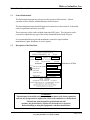
1.2
Description of the Data Plate
HICKORY INDUSTRIES, INC.
COMMERCIAL COOKING APPLIANCES
N O RT H B E R G E N , N J
MODEL N/45
07047
SERIAL NO.
MOTOR: 110 - 115 VOLTS 60 CYCLE AC CURRENT
1/3 HP
SINGLE PHASE
1725 RPM
BURNERS
LISTED
3
*4 burners for 45 Plus
GAS INPUT PER BURNER
60,000
MANIFOLD
5.5"
69D6 PRESSURE
TYPE OF GAS
BTU/H
NAT
MFG. DATE
MINIMUM INSTALLATION CLEARANCE
SIDE: 6 INCHES
BACK: 6 INCHES
MAXIMUM LAMP WATTAGE: 150 WATTS
FOR INSTALLATION ON A COMBUSTIBLE FLOOR
Gas-fired Food Service Equipment Classified by
Underwriters Laboratories Inc. In accordance with American
National Standards Institute ANSI Z 83.11b-1991, Gas Food
Service Equipment-Ranges and Unit Boilers
WARNING!
This unit must be installed and connected in accordance to the latest regulations
and can only be operated in conjunction with forced ventilation or exhaust hood.
This unit has been designed for professional use only
and may only be installed or repaired by licensed service agencies!
Before installing or using this equipment, read these instructions!
4900 Westside Avenue, North Bergen, New Jersey 07047
Tel: [201] 223-0050 Fax: [201] 223-0950
N/45 Series Manual12/00
Page 5 of 38
Hickory Industries, Inc.
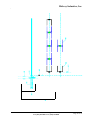
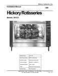
1.3 Machine Drawings and Dimensions
4900 Westside Avenue, North Bergen, New Jersey 07047
Tel: [201] 223-0050 Fax: [201] 223-0950
N/45 Series Manual12/00
Page 6 of 38
Hickory Industries, Inc.
1.4
Conversion and Adjustment Instructions
Before converting or adjusting the machine, it is imperative that the manual gas cock be
turned to the "off" position. The electrical power to the machines should also be turned off.
When converting from one type of gas to another, the main gas orifice (or injector), the
pilot burner orifice (or injector), and the primary air adjustment must be changed according
to the table on page 9. In addition, the spring in the pressure regulator must be changed so
that it can operate at higher pressures.
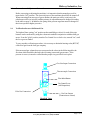
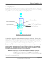
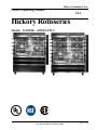
1.6
Verification for use with Natural Gas
The highest flame setting ("on" position on the manifold gas valves) for each of the pipe
burners can be confirmed by using the volumetric method in conjunction with the main gas
meter. From the "pilot" position, turn the Gas Control Lever clock-wise, towards "on", until
the lever goes no further.
To carry out this verification procedure, it is necessary to obtain the heating value (BTU/ft3)
of the local gas from the local gas company.
If the measured gas volume does not correspond to the values in the following table, the
first item which should be checked is the incoming (connected) gas pressure. If the
pressure is correct, it must be verified that the proper size gas orifices are in place.
Gas Line Input Connection
Thermocouple Connection
Flow Index Button
Gas Control Lever
(in Pilot position)
Pilot Gas Connection
Gas Line Output
(connection to venturi)
Manifold Valve
4900 Westside Avenue, North Bergen, New Jersey 07047
Tel: [201] 223-0050 Fax: [201] 223-0950
N/45 Series Manual12/00
Page 7 of 38
Hickory Industries, Inc.
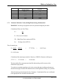
1.7
Natural Gas Flow Table
Heating Value in
BTU/ft³
Gas
Natural
Propane
Butane
1.7.1
1040
2500
2500
Gas Flow
per Burner (40,000 BTU)
in ft3/hr
High Flame Setting
57.75
24.00
24.00
Volumetric Method to Verify the High Flame Setting, Mathematical
WARNING! No other gas equipment can be in operation during this procedure.
Calculation of flow rate E in ft3/hour
E=
FP
Hi
E = Flow rate in ft3/minute
FP = High Flame Power setting in BTU/hr
Hi=
Heating value in BTU/ft3
Thus, for natural gas:
E = 60,000
1040
BTU/hr
BTU/ft3
=
57.75 ft3/hr
=
0.96 ft3/min.
E = 0.96 ft3/min.
Calculation of the natural gas needed in 1 hour by a 45WDG (3 burners) at full power:
57.75 * 3 =
173.25 ft3/hr
=
2.89 ft3/min.
The time and the flow measurements should be taken at the gas (flow) meter with a
chronometer (stop watch).
To run the test, open the manual gas cock valve, start up the unit according to the start-up
instructions on page 24 and set the manifold valves to the high flame setting ("on" position).
Allow the unit to pre-heat (burn) for 10 to 15 minutes. Verify that the flow rate is calibrated
to the appropriate flow rate indicated in the table.
4900 Westside Avenue, North Bergen, New Jersey 07047
Tel: [201] 223-0050 Fax: [201] 223-0950
N/45 Series Manual12/00
Page 8 of 38
Hickory Industries, Inc.
1.8
Orifice Diameters, Primary Air Intake Settings, and Pressure Regulators
Gas / Pressure
Main Orifice
Pilot Orifice
Primary Air Intake
inches W.C.
Ø in drill size
Orifice Marking
in inches
Natural / 5.5"
5 holes @#55
3211
3/16 "
1/8 "
1/8 "
Propane / 11"
2 holes @#55
3221
3/16"
Butane / 11"
2 holes@#55
3221
3/16"
4900 Westside Avenue, North Bergen, New Jersey 07047
Tel: [201] 223-0050 Fax: [201] 223-0950
N/45 Series Manual12/00
Page 9 of 38
Hickory Industries, Inc.
1.9
Changing Gas Orifices
1.9.1
Changing the Main Gas Orifice
1.
2.
3.
4.
The venturi tubes and manifold valves are on the same side as the spit handles.
On each venturi, loosen the lock nuts (7/8" wrench) and then move the nut
and the air intake cap all the way to the top of the nipple.
With a 3/4" wrench, loosen the nipple so that it can be removed from the
venturi.
With the nipple/orifice assembly off, separate the main orifice from the
nipple with a pipe wrench or a pair of pliers.
Nipple
Air Intake Cap
Air Intake Adjustment
Lock Nut
Main Orifice
Venturi Tube
Venturi Assembly
Re-assemble all of the components with the new main orifice. Make sure that the proper air intake
adjustment is made for the new type of gas (according to the tables on page 9). The flames should be
blue in color, must be stable, and must not "lift off" the burner.
4900 Westside Avenue, North Bergen, New Jersey 07047
Tel: [201] 223-0050 Fax: [201] 223-0950
N/45 Series Manual12/00
Page 10 of 38
Hickory Industries, Inc.
1.9.2
Changing the Pilot Orifice
1.
To reach the pilot burner, open the sliding glass doors, the sliding or hinged metal
door, remove all spits, as well as all ceramics.
2.
Before removing, mark the position of the support bracket on the side wall.
3.
Loosen the pilot burner assembly by removing the two screws which attach each
pilot burner (support bracket) to the main body of the machine.
4.
With the assembly loose, carefully pull the entire assembly forward about 6".
Pilot Orifice
Pilot Flame
Openings
Thermocouple
Pilot Burner Assembly
5.
Loosen the gas line connection to the pilot orifice with a 7/16" wrench. Carefully
separate the gas line from the pilot burner. From the pilot burner, carefully
remove the pilot orifice using a 1/2" wrench.
6.
Reassemble the pilot burner using the new pilot orifice and place the support bracket
in its original position. The following pilot orifices are to be used with each type of
gas.
Pilot Orifice
LPG
Marking
3221* Verbally confirm model 45 when ordering.
Natural Gas
3211*Verbally confirm model 45 when ordering.
4900 Westside Avenue, North Bergen, New Jersey 07047
Tel: [201] 223-0050 Fax: [201] 223-0950
N/45 Series Manual12/00
Page 11 of 38
Hickory Industries, Inc.
1.10
Checking the Connected Gas Pressure (Nominal Pressure)
Close the gas cock where the gas line is connected to the machine and attach a manometer
to the tap (allen screw) on the gas cock. With the manometer connected, open the gas
cock, ignite all burners, and set the manifold valves to "on" or maximum setting. Along with
all other gas appliances at the location in operation, measure the gas pressure.
This nominal pressure should be 5.5" W.C. for natural gas and 11" W.C. for LPG.
If the measured pressure falls below the range mentioned above, the installer should try to
find the cause of the problem and resolve it. A typical source of this problem is that the gas
line (pipe) diameter leading up to the unit is too small. If it is not possible to resolve the
problem, the local gas company or gas supplier should be contacted so that they can resolve
the problem.
If the nominal pressure is below 5.5 " W.C. for natural gas or below 11 " W.C. for LPG, the
unit should not be operated. These should be adjusted to the ideal settings using the pressure
regulating screw on the pressure regulator.
If the pressure is too high and can not be adjusted downward, check to see if the proper
adjusting spring is in place. If this is correct, the regulator membrane may have been
ruptured by excessive gas pressure and may have to be replaced. Do not operate the
rotisserie if the gas pressure is too low.
If the pressure is too low and can not be adjusted upward, also check the regulator. If this is
correct, verify the pressure coming out of the main gas meter or the diameter of the gas pipe
feeding gas to the unit. If the gas line is under-sized, the appropriate pressure may not be
reached. Do not operate the unit if the pressure falls below 5.5" W.C.
After the pressure has been set, close the gas cock once again, remove the manometer, seal
the pressure regulator, and then re-open the gas cock.
WARNING: After an installation, repairs, or maintenance, make sure that there are
no gas leaks anywhere in the gas lines or system.
1.11
Maintenance, response to technical problems, reasons for problems and solutions
Should a technical problem arise for any reason, shut off the machine and call for technical
service.
4900 Westside Avenue, North Bergen, New Jersey 07047
Tel: [201] 223-0050 Fax: [201] 223-0950
N/45 Series Manual12/00
Page 12 of 38
Hickory Industries, Inc.
A routine maintenance should be carried out at least once a year. Contact your local,
certified service company for maintenance.
Problem
Burners do
not ignite.
a.
b.
Pilot burner
a.
ignites. Main
burner initially b.
ignites, but
then goes out.
c.
d.
Burners too
weak.
Burner
back-fires.
Pilot flame
does not stay
on.
1.12
e.
a.
b.
a.
b.
Cause
No gas flow.
Gas container too cold
especially with butane.
Water in gas freezes
in gas regulator.
b.
Solution
Make sure that all gas valves are
open and that gas is reaching unit.
Remove and control the gas valve
at the connection (manual) or the
LPG pressure regulator. Contact
gas company or distributor.
Thermocouple tip is not
enveloped by pilot flame.
Thermocouple is not
heated enough by flame or
it is being heated along the
entire length too much.
Primary air intake blocked
or must be adjusted.
Thermocouple is loose at
one of the connections.
Defective thermocouple.
Gas pressure too low.
Wrong orifice size.
Too much primary air.
a.
Adjust thermocouple position.
b.
Flames on pipe burners
disrupting pilot flame.
Defective thermocouple.
a.
Only the themocouple tip should be
enveloped by the pilot flame and
heated. The pilot flame must be
strong and blue in color.
Clean or adjust opening according
to table in page 9.
Tighten all thermocouple
connections.
Replace thermocouple (service co.).
Contact service or gas company.
Install correct orifices.
Adjust the primary air intake.
(contact service company)
Block off holes on the main burner
pipe directly below the pilot burner.
Replace thermocouple (service co.).
a.
c.
d.
e.
a.
b.
b.
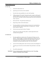
Testing or checking for safety
After a conversion, a new installation, or after a repair, it is important that the unit be
tested to insure that it operates properly. This should include the following:
Test for gas leaks.
Check that the unit has enough clearance behind and to the sides.
Check that enough primary and secondary air is available (strong blue flames).
Check for potentially flammable objects or potential flammability problems.
Check the gas distribution systems.
Check for proper ventilation and exhaust.
Check for proper room ventilation.
4900 Westside Avenue, North Bergen, New Jersey 07047
Tel: [201] 223-0050 Fax: [201] 223-0950
N/45 Series Manual12/00
Page 13 of 38
Hickory Industries, Inc.
When first installing, after repairing, or after cleaning the units, it is important to make
sure that all components are properly in place.
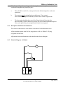
1.14
a.
There should be a total of 9, evenly spaced ceramic bricks sitting above each main
pipe burner.
b.
The ceramics must be sitting directly on the burners. These ceramic
bricks should also be placed so that they fit between the ceramic support rods.
c.
The burner pipes should not have any holes (flames) directly below the pilot
burner assembly. If holes (flames) are present, they will overheat the thermocouple or
blow out the pilot flame, preventing the main burner from staying lit.
Description of the Electrical Connection
The electrical connections are to be made in accordance to local and national codes.
All gas machines operate with 120 Volt, single phase, 60 Hz. A NEMA 5-15P plug
is supplied with the units.
All pertinent electrical information can be taken from the electrical diagram.
1.15
Electrical Diagram - All Models
L
M
L
N
4900 Westside Avenue, North Bergen, New Jersey 07047
Tel: [201] 223-0050 Fax: [201] 223-0950
N/45 Series Manual12/00
Page 14 of 38
Hickory Industries, Inc.
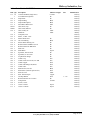
1.16
Parts List for N /4 5WDG
Item Qty.
113 39
1
120 2
121 2
122 2
131 2
409T 1
409B 1
410 2
2
150 2
155 2
157 2
158 33
159 6
414 2
415 3
182 1
184 22
420 2
421 1
414 1
227 3
229 3
231 3
233 3
234 3
232 3
162 3
163 3
164 3
138 3
175 3
152 2
214 3
110 2
111 2
Description
Ceramic Radiants (Single Face)
Accordian Door (Option)
Drip Pan45
Drip Pan Plug
Drip Pan Receptacle
Fiber Motor Worm Gear
Glass Track, Top
Glass Track, Bottom
Glass Trolley 45
Handle 45
Lamp Par, 120 V
Motor, 1/3 HP - 120V
Motor Worm Steel
Oil Lite Bushing
Pillow Block Bearing 5/8"
Reflector Panel 45WDG Curved
Reflector Panel 45 WDG Flat
Shaft 5/8"
Shaft Worm
Spit Plate, N/45 Exterior
Spit Plate, N /45 Center
Top Reflector Single
Venturi Cap
Venturi Lock Nut 3/8" ID, 3/4" OD
Venturi Nipple
Venturi Threading Tube, Brass
Venturi Tube
Main Orifice, Nat. Gas
Pilot Burner (includes pilot orifice)
Pilot Gas Line
Pilot Thermocouple
Gas Pipe Burner
Retainer Rod 45 for Ceramics
Lamp Socket
Switch, 1-Pole
Caster w/ brake
Caster w/o brake
Material Length
Ceramic
SS
SS
Brass
Brass
Fiber
SS
SS
Alum.
Alum.
SS
Brass
SS
SS
SS
SS
Nylon
SS
SS
SS
Iron
Iron
Steel
Steel
Iron
Brass
Steel
Alum.
Copper
Steel
SS
Ceramic
Size
1 - 1/2"
Nylon
Nylon
4900 Westside Avenue, North Bergen, New Jersey 07047
Tel: [201] 223-0050 Fax: [201] 223-0950
Manufacturer
Hickory
Hickory
Hickory
Hickory
Hickory
Hickory
Hickory
Hickory
Hickory
Hickory
Hickory
Hickory
Hickory
Hickory
Hickory
Hickory
Hickory
Hickory
Hickory
Hickory
Hickory
Hickory
Hickory
Hickory
Hickory
Hickory
Hickory
Hickory
Hickory
Hickory
Hickory
Hickory
Hickory
Hickory
Hickory
Hickory
Hickory
N/45 Series Manual12/00
Page 15 of 38
Hickory Industries, Inc.
1.16
Parts List for N / 45WDG (Contd.)
Item Qty.
Description
Material Length
417 9
Spit Regular Complete (with screws)
179 2/spit Roll Pin 1/8" Stainless
190 9
Spit Regular, without collar
191 9
Spit Collar
192 9
Spit Gear
419 9
Spit Handle, 6" Short
185 4/Spit Skewer Double
186 2/Spit Skewer Single
219 6/Acc. Thumb Screw
408 2
Tempered Glass 30"x33 3/4"
407 2
Glass Frame 45
165 1
Pressure Regulator 3/4"
7A 1
Pipe
135 1
Gas Cock Valve
7B 1
Pipe
7C 3
T-Connector
7D 6
Nipple (Adapter 3/4" to 3/8")
132 3
Flexible Pipe
180 3
Manifold Gas Valve
7E 3
Nipple
226 3
Venturi Assembly
228 3
Venturi Elbow, 90º
7F
1
Pipe
7G 1
Pipe
7H 1
Pipe Cap (threaded)
SS
SS
SS
SS
Nylon
Nylon
SS
SS
SS
Tempered Glass
SS
Alum.
Steel
3.5"
Steel
Steel
6"
Steel
Steel
1.7"
SS
4.25"
SS
Steel
1.5"
Iron
Iron
Steel
14.5"
Steel
16"
Steel
Size
Manufacturer
Hickory
Hickory
Hickory
Hickory
Hickory
Hickory
Hickory
Hickory
Hickory
Hickory
Hickory
Maxitrol
Hickory
3/4"
3/4"
3/4"
3/4"
3/4"
3/8"
3/8"
3/8"
3/8" - 1-1/2"
1-1/2"
3/4"
3/4"
3/4"
Hickory
Hickory
Hickory
Dormont
Baso
Hickory
Hickory
Hickory
Hickory
Hickory
Hickory
The following parts are not shown in the diagrams:
123
1
104
105
1
1
1
Electrical Grounding Cap
Electrical Wire
Connection Cable
Contact Section 242 (terminal)
Contact Section 250 (end-piece)
Hickory
Janor Wire
TIP Products
Buchanan
Buchanan
*All components are inventories and sold through Hickory Industries and their distributors and dealers.
4900 Westside Avenue, North Bergen, New Jersey 07047
Tel: [201] 223-0050 Fax: [201] 223-0950
N/45 Series Manual12/00
Page 16 of 38
Hickory Industries, Inc.
4900 Westside Avenue, North Bergen, New Jersey 07047
Tel: [201] 223-0050 Fax: [201] 223-0950
N/45 Series Manual12/00
Page 17 of 38
Hickory Industries, Inc.
4900 Westside Avenue, North Bergen, New Jersey 07047
Tel: [201] 223-0050 Fax: [201] 223-0950
N/45 Series Manual12/00
Page 18 of 38
Hickory Industries, Inc.
4900 Westside Avenue, North Bergen, New Jersey 07047
Tel: [201] 223-0050 Fax: [201] 223-0950
N/45 Series Manual12/00
Page 19 of 38
Hickory Industries, Inc.
II. Operating Instructions
1.0 Start Up
a.
Switch the exhaust hood to on.
b.
Open the gas cock at the rear of the machine.
c.
Turn the knob on the manifold valve to the "pilot" position.
d.
While pressing the "flow index" button down, place a match, or other type of
ignition method, to the pilot burner until it is lit. Keep the knob pressed down
for at least 40- 60 seconds so that the thermocouple tip warms up and the pilot
flame remains lit.
e.
Release the knob. The pilot flame should stay on.
f.
Repeat the procedure for the other burners.
g.
Turn the manifold valve knob to the desired setting ("on" must be lined up
with the "flow index" button for high flame or maximum heat). The pipe
burner should now light up.
h.
Allow the unit to pre-heat for about 15 minutes.
i.
When ready to load the spits with product, turn the light and the motor
switches to the on position.
2.0 Shut Down
a.
Turn the manifold valve knobs to the "off" position if all flames are to be
shut off. If the pilot light is to remain lit and only the pipe burners are to be
shut off, turn the manifold valve knobs to the "pilot" position. Note that to
turn the knobs to the "off" position, one must pull out on the locking
mechanism on the knobs and then turn the valve to the off position.
b.
After all of the loaded spits have been removed, turn the motor and lights off.
c.
Close the gas cock at the rear of the machine if the pilot flames are also shut
off.
d.
Turn off the exhaust hood.
WARNING! Do not clean the machine or glass while these are hot! Everything
should be cooled down before cleaning.
4900 Westside Avenue, North Bergen, New Jersey 07047
Tel: [201] 223-0050 Fax: [201] 223-0950
N/45 Series Manual12/00
Page 20 of 38
Hickory Industries, Inc.
3.0 Working with the Rotisserie
A. Cooking Temperature
The desired temperature in the rotisserie can only be set with the manifold valve knob. Setting "on"
is for the high flame setting and represents about 540°F. The grilling temperature can be reduced by
turning the knob counter clock-wise (CCW), towards the "pilot" position.
Flow Index Button
Reduced Flame Setting
"Off" Locking Mechanism
High Flame Setting
Gas Control Lever
Manifold Valve Knob in "Pilot" Position
As a general rule, the higher the grilling temperature, the shorter the cooking time. However, when
working with the Old Hickory rotisserie, one must consider that the temperatures will vary from top
to bottom. The top of the unit will have higher temperatures due to the natural convection. The
cooking temperatures indicated above refer to the top section of the machine. For this reason, the
product on the top spits will be cooked faster than the product on the lower spits.
This factor allows for continuous cooking. As the top spits are ready, they should be removed. The
spits directly below should then be moved up one spit position, thus freeing a spit position at the
bottom of the unit. This bottom position can then be loaded with fresh, raw product. By loading
raw product to the bottom, there is no danger of cross contamination.
WARNING: The only way to be sure that the product is completely cooked is by
taking the internal temperatures. For example, with poultry, the
internal temperature must be at least 185°F at the inner side of the thigh.
For example, when preparing chicken.
4900 Westside Avenue, North Bergen, New Jersey 07047
Tel: [201] 223-0050 Fax: [201] 223-0950
N/45 Series Manual12/00
Page 21 of 38
Hickory Industries, Inc.
4.0 Cooking Times
Product
Cooking Time
Temperature
Chicken
45 - 60 minutes
"ON"
Turkey
120 - 170 minutes
Ribs
20 - 45 minutes
1/2 power
increase to "ON" for last 20 min.
"ON"
Beef Roast
45 minutes (to 104°F)
"ON"
Pork Loin
45 minutes (to 135 °F)
"ON"
Salmon
20 - 30 minutes
"ON"
Duck
120 minutes
Vegetables
(Zuccini)
Potatoes
20 minutes
1/2 power - 105 minutes
"ON" - 15 minutes
"ON"
40 minutes
"ON"
5.0 Spitting Chickens
The most important part in getting started with a rotisserie is knowing how to properly spit the product.
This is quite easy, but it must be learned! As an operator, you will become an expert in spitting chickens within half an hour! There are two types of commomly used spits: the angle spit and the regular
spit. The following pages describe and show how spitting is done with both these types of spits.
4900 Westside Avenue, North Bergen, New Jersey 07047
Tel: [201] 223-0050 Fax: [201] 223-0950
N/45 Series Manual12/00
Page 22 of 38
5.0 Spitting Chickens
A. Using Angle Spits
Hickory Industries, Inc.
Figure 1. Chickens Ties
When using a “V” or angle spit, it is very important
to tie or truss the product being cooked. This
prevents the product from moving around the spit
and also prevents damage by preventing the legs and
wings from flopping. In this section, we will show
how to properly truss a chicken. It is important to
use a tie to fit the size of the product. In this case,
we are tieing a 2 3/4 lb. chicken with a 6” tie.
Figure 2. Trussing Wings
With the back of the chicken facing up, take the tie
and wrap it around the breast, making sure to tuck
the wings against the breast. Pull on the tie as
pictured. You will also need to hold the chicken
with your other hand.
Figure 3. Trussing Accross Back
While pulling on the tie, cross the strings so that you
make an “X” across the back of the chicken. With
the “loop” in your hand, you will now need to tie the
legs of the chicken.
4900 Westside Avenue, North Bergen, New Jersey 07047
Tel: [201] 223-0050 Fax: [201] 223-0950
N/45 Series Manual12/00
Page 23 of 38
Hickory Industries, Inc.
Figure 4. Trussing Legs
While pulling on the tie, loop the strings over the
legs of the chicken.
Figure 5. Trussed Legs
Make sure that both legs are securely held by the tie.
Figure 6. Trussed wings
Make sure that both wings are securely held by the
tie against the breast of the chicken.
4900 Westside Avenue, North Bergen, New Jersey 07047
Tel: [201] 223-0050 Fax: [201] 223-0950
N/45 Series Manual12/00
Page 24 of 38
Hickory Industries, Inc.
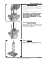
Figure 7. Pop-up Thermometer
The only way to tell if a chicken is done is take the
intermal temperature. Since it can be difficult to
probe the chickens while they are in the rotisserie,
we recommend the use of pop-up thermometer.
These inexpensive items should be place in the
thickest part of the chicken, which is the breast. The
thermostat will “pop-out” when the internal temperature reaches 185º F.
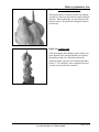
Figure 8. Chicken Ready to Spit
With the chicken trussed and the pop-up thermometer in place, the chicken is ready to be spitted with
an angle spit.
Figure 9. Spitting Accessories
In order to make the use of the angle spits fast and
easy, we offer an accessorie called a Spit Holder
(Hickory Part 195). This aluminum plate offers six
holes where the base (square-end) of the angle spit
can be inserted.
4900 Westside Avenue, North Bergen, New Jersey 07047
Tel: [201] 223-0050 Fax: [201] 223-0950
N/45 Series Manual12/00
Page 25 of 38
Hickory Industries, Inc.
Figure 10. Using the Angle Spit
Insert the bottom (handle) of the spit into the Spit
Holder.
Figure 11. Spitting a Chicken
Spit the chicken through the cavity. The chicken
should be inserted through the “head” (or at least
where the head used to be) first.
Figure 12. Chicken Position on Spit
When spitting the chicken, make sure that the breast
is sitting on the flat, exterior side of the spit. Notice
on the picture how the breast is not directly on the
rounded corner of the spit, but above one of the flat
parts of the “V”. It is also important to note that the
legs (and the tie) must sit on the same flat side of the
spit. This picture shows exactly how the chicken
should look when spitted.
4900 Westside Avenue, North Bergen, New Jersey 07047
Tel: [201] 223-0050 Fax: [201] 223-0950
N/45 Series Manual12/00
Page 26 of 38
Hickory Industries, Inc.
Figure 13. Incorrectly Spitted Chicken
This picture shows a chicken with the legs improperly placed. Note how the chicken seems to hang to
one side. When spitted this way, the chickens will
tend to “bounce” up and down causing the chicken
to break-up.
Figure 14. Complete Spit
After inserting the first chicken, push it all the way
to the bottom of the spit and add the next chicken.
Depending on the size of the birds and on the
rotisserie model, each spit will accommodate three
to four 2 3/4 lb. chickens. Once completed, the spit
is ready to be placed in the rotisserie.
4900 Westside Avenue, North Bergen, New Jersey 07047
Tel: [201] 223-0050 Fax: [201] 223-0950
N/45 Series Manual12/00
Page 27 of 38
B. Using Regular Spits
Hickory Industries, Inc.
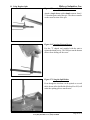
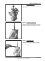
Figure 15. Inserting Single Bottom Skewer
Attach a single skewer with a thumb screw at least 1/
2" from the square end of the spit. The skewer must be
on the round section of the spit.
Figure 16. Fastening Bottom Skewer
Use the "T" shaped tool supplied with the unit to
tighten the thumb screw. This will prevent the bottom
skewer from sliding off the screw.
Figure 17. Using the Spit Holder
Even though the chickens can be spitted on a work
table, the use of the Spit Holder (Hickory Part 195) will
make the spitting process much easier.
4900 Westside Avenue, North Bergen, New Jersey 07047
Tel: [201] 223-0050 Fax: [201] 223-0950
N/45 Series Manual12/00
Page 28 of 38
Hickory Industries, Inc.
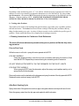
Figure 18. Inserting Chicken
Take the chicken, with the drumsticks in the direction
of the attached skewer, and slide the spit through the
cavity of the chicken.
Figure 19. Tucking the Legs
The legs must be tucked between the skewer prongs
and the center spit. Note that the bottom of the
drumstick is what is being locked in place.
Figure 20. Pressing Chicken Towards Skewer
When viewed from the breast side of the chicken,
the bottom of the drum-stick is being pushed back
while the meaty part of the leg is “puffed up” for
better presentation. Note that the skewer is not
going straight through the drum-stick!
4900 Westside Avenue, North Bergen, New Jersey 07047
Tel: [201] 223-0050 Fax: [201] 223-0950
N/45 Series Manual12/00
Page 29 of 38
Hickory Industries, Inc.
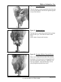
Figure 21. Locking Wings
The wings must be locked or tucked in place.
When using the models N/5.5 and N/10.10, the
locking method (pictured here) is only recommended with birds up to 2¾ lbs! With larger
birds, the wings must be tucked under the breast,
with elastic ties or “wing tuckers”. If the wings are
locked on large birds, the wings on the adjacent
spits will rub or catch, preventing the spits from
rotating freely. This will cause the wings to break
off or the gear mechanism to jam.
Figure 22. Tucking Wings
With larger birds, the wings must be tucked under
the breast, with elastic ties or “wing tuckers”.
Figure 23. Tucked Wings
Notice how the wings are tucked agains the breast.
By “tucking” instead of “locking” the wings, the
working or rotating diameter of the chicken has
been reduced.
4900 Westside Avenue, North Bergen, New Jersey 07047
Tel: [201] 223-0050 Fax: [201] 223-0950
N/45 Series Manual12/00
Page 30 of 38
Hickory Industries, Inc.
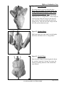
Figure 24. Inserting Double Skewers
With the first chicken in place, insert a double skewer
down the length of the spit into the shoulders of the
first chicken. No thumb screw is required for the
double skewers!
WARNING! When driving the double skewer
into the chicken, do not exert pressure from the
end of the prongs! These are sharp and will
pierce a finger or hand if not careful. Only
apply pressure at the bottom of the "U" shaped
half of the skewer!
Figure 25. Double Skewer in Place
With the double skewer in place, insert the next
chicken down the length of the spit and position the
chicken as previously described.
Figure 26. Loaded Spit
When the loading of the chickens is complete, the
end of the spit must be locked in place with another
single skewer.
4900 Westside Avenue, North Bergen, New Jersey 07047
Tel: [201] 223-0050 Fax: [201] 223-0950
N/45 Series Manual12/00
Page 31 of 38
Hickory Industries, Inc.
Figure 13. Completing the Load
Slide a single skewer with a thumb screw into place
from the top,
Figure 14. Tightening Final Skewer
Compress the chickens by exerting pressure on this
last skewer, and tighten the thumb screw securely.
Figure 15. Securing the Load
Tighten the thumb screws with Hickory's thumbscrew tightening tool. This will prevent the chickens from coming loose.
4900 Westside Avenue, North Bergen, New Jersey 07047
Tel: [201] 223-0050 Fax: [201] 223-0950
N/45 Series Manual12/00
Page 32 of 38
Hickory Industries, Inc.
6. Loading and Unloading Spits
On the N/45G, you do not need to open the front sliding glass doors of the machine in order to
load the spits! If your unit is equipped with hinged side doors, these must be opened in order to
insert and/or remove the spits. With the side(s) open, use a barbecue fork to grab a spit on one end,
inside the single skewers. You can then use your free hand to hold the spit handle. With the motor
switch on or off, first insert the round end of the spit and position it on the oil lite bushing on the
center plate (see Figure 27). Then position the spit gear (next to the handle) so that it meshes with
the shaft worm on the vertical drive shaft. Shift the spit from side to side so that the space formed
between the spit collar and the spit gear fits fits (falls) onto the oil lite bushing on the spit plate.
Reverse procedure to unload.
Figure 27
Shaft Worm
Spit Plate
Spit Gear
Spit Collar
Oil Lite Bushing
Figure 28
4900 Westside Avenue, North Bergen, New Jersey 07047
Tel: [201] 223-0050 Fax: [201] 223-0950
N/45 Series Manual12/00
Page 33 of 38
Hickory Industries, Inc.
7.
Checking Chickens for Doneness
Depending on the model being used, a 2 1/2 lb. chicken will take between 50 minutes and 1 hour 20
minutes to cook in a pre-heated oven when the thermostat is set for MAXIMUM. By using a stem
type thermometer, the operator MUST determine the interior temperature of the chicken to test for
doneness. Chicken is done at 185°F. MAKE SURE TO REMOVE THE SKEWERS FROM
BETWEEN THE CHICKENS PRIOR TO SERVING IT TO CUSTOMERS.
8. Cooking other Products
These units can be used to cook anything from quail to turkeys, pigs, lamb, goat, vegetables, potatoes,
fish and much more. The baskets can be used for the cooking of chicken parts, brochettes and anything else that cannot go on a spit. A variety of other accessories is also available for specific types of
products. Please consult the factory for a complete list of cooking accessories.
9. Cleaning Instructions for Continuous Cook Rotisseries
The most effective maintenance procedure that you can perform will be the daily cleaning procedure
Prior to First Cook:
While the oven is still cold – spray all interior panels with KOTE.
FOR GAS MODELS
Using the shield provided, cover the top row of ceramics and spray the interior of that
area with KOTE. Repeat the process covering the remaining rows of ceramics.
DO NOT SPRAY KOTE DIRECTLY ON THE CERAMICS OR THE PILOT LIGHTS.
FOR ELECTRIC MODELS
When spraying KOTE near the elements, adjust the spray nozzle pattern and try not to
spray directly on the elements.
Remove the wire rack located above the drip pan and spray the sides of the drip pan with KOTE.
Replace the wire rack and spray it with KOTE.
After Each Cooking Cycle
Spray the inside of the glass doors with an approved glass cleaner and wipe with a soft cloth.
Drain the greasy water from the drip pan and replenish with fresh water.
4900 Westside Avenue, North Bergen, New Jersey 07047
Tel: [201] 223-0050 Fax: [201] 223-0950
N/45 Series Manual12/00
Page 34 of 38
Hickory Industries, Inc.
At The End of Each Day
Turn burners valves or element switches to the “OFF” position and allow the oven to cool down.
Remove any spits or baskets – allow them to soak for 15 – 20 minutes, using a solution of warm
water and detergent. Rinse clean, following guidelines for rinsing & sanitizing.
Remove the wire rack – and clean it in the sink using a solution of warm water and detergent.
Drain the greasy water from the drip pan and replenish with a solution of warm water and detergent.
Using either a sponge or a cloth - wipe down the interior of the oven with the solution removing any
grease/fat. Wipe dry the interior of the oven with a soft cloth.
USE CARE WHEN CLEANING NEAR THE PILOT ASSEMBLY. IF YOU ACCIDENTALLY
MOVE THE THERMOCOUPLE, BE SURE THAT YOU SNAP IT BACK INTO POSITION.
Drain the solution from the drip pan, wipe clean and return to the oven along with the wire rack.
Clean the glass with an approved glass cleaner. Do not use abrasives or razor blades as they will
mar and/or scratch the surface causing it to break without notice.
Wipe clean the area around the controls with a sponge or soft cloth.
GAS MODELS
RE-LIGHT THE PILOTS AND TURN ON ALL BURNERS (SET TO HIGH).
ELECTRIC MODELS
TURN ON ALL OF THE ELEMENTS.
RUN THE UNIT FOR APPROXIMATELY 5 MINUTES TO BURN OFF ANY CHEMICAL
RESIDUE THAT MAY BE REMAINING FROM THE CLEANING PROCEDURE.
Recommendation – now would be a good time to spray the interior of the oven with KOTE. You
will be prepared for tomorrow’s cooking cycle.
NOTE:
On a monthly basis, to ensure that the burner is operating efficiently, remove the
ceramics and use a paper clip to clean any debris from the burner openings. Additionally the
venturi air inlet gap needs to be cleaned. This can be done using a paring knife or business
card. Refer to the operating manual.
4900 Westside Avenue, North Bergen, New Jersey 07047
Tel: [201] 223-0050 Fax: [201] 223-0950
N/45 Series Manual12/00
Page 35 of 38
Hickory Industries, Inc.
10. Maintenance Procedures for Continuous Cook Rotisseries
The most effective maintenance procedure that you can perform will be the daily cleaning
procedure.
Monthly:
To ensure that the burner is operating efficiently, remove the ceramics and use a paper clip to clean
any debris from the burner openings.
To ensure proper air/gas mixture, the venturi air inlet gap needs to be cleaned. This can be done
using a paring knife or business card. Refer to the operating manual.
Every 6 Months:
To ensure that the shaft worm nylon gears properly mesh with the spit gears, place a spit into each
spit position with the motor running. If the gears jump or do not align properly, adjust them using
the allen wrench provided – DO NOT OVER TIGHTEN THE SCREWS.
Every 12 Months:
Inspect the spit plates and verify that the brass oil lite bushings are in place for each spit position.
Replace any worn or missing bushings.
Remove the glass and inspect for scratches and or chips. If any are found replace the glass as
soon as possible. Also, inspect the glass trolleys. If they are worn, replace them.
Units with sliding side doors – the upper and lower slides needed to be greased.
4900 Westside Avenue, North Bergen, New Jersey 07047
Tel: [201] 223-0050 Fax: [201] 223-0950
N/45 Series Manual12/00
Page 36 of 38
Hickory Industries, Inc.
III.
CRITICAL CONTROL STEPS FOR PREPARATION AND COOKING OF
BARBECUE CHICKENS
1.
Clean and sanitize preparation sink.
2.
Clean and sanitize spits, skewers, and thumbscrews.
3.
Use only the designated sink for raw product.
4.
Rinse off chickens in the preparation sink.
5.
Follow product spit-up procedure in manual.
6.
Load spitted product into machine. Follow loading
instructions in manual.
7.
Thoroughly wash and sanitize hands before touching
switches and/or dials.
8.
Follow operating instructions for oven operation.
9.
Check product for doneness as per instruction manual.
10.
Follow unloading procedures. Use a designated surface for cooked product
only. Insure that no cross contamination occurs with any surface previously
used for raw product, including employee hands.
11.
If placing product in a display warmer, ensure that the product temperature
(NOT WARMER TEMPERATURE) does not fall below 140°F. Warmer temperature insures that the ambient air temperature in the warmer is correct, but
does not insure product temperature.
12.
Advanced preparation and storage of spitted product should be in an authorized, properly covered and maintained bin set aside for storing spitted product
in the walk-in refrigeration unit.
13.
THE MOST CRITICAL STEP IN THE PREVENTION OF CROSS CONTAMINATION IS THE HUMAN HAND. THEREFORE, HANDLING RAW PRODUCT AND THE WASHING OF HANDS IS THE MOST CRITICAL CONTROL
STEP IN PREVENTING CROSS CONTAMINATION.
4900 Westside Avenue, North Bergen, New Jersey 07047
Tel: [201] 223-0050 Fax: [201] 223-0950
N/45 Series Manual12/00
Page 37 of 38
Hickory Industries, Inc.
IV. WARRANTY
HICKORY INDUSTRIES WILL WARRANTY ALL ROTISSERIES FOR ONE YEAR FROM
THE DATE OF ORIGINAL INVOICE. WARRANTY INCLUDES ALL PARTS EXCEPT
BULBS AND GLASS.
WARRANTY CONDITION IS THAT ALL
WARRANTY
DOCUMENTS MUST BE SIGNED AND MUST BE RETURNED TO HICKORY BY THE
USER AFTER RECEIPT OF THE ROTISSERIE. THE COMPANY (HICKORY) RESERVES
THE RIGHT TO REVIEW ALL WARRANTY
CLAIMS
BY
ITS AUTHORIZED
REPRESENTATIVE AND IF NEGLIGENCE OR ABUSE IS FOUND, THE CLAIM WILL
BE DISALLOWED.
4900 Westside Avenue, North Bergen, New Jersey 07047
Tel: [201] 223-0050 Fax: [201] 223-0950
N/45 Series Manual12/00
Page 38 of 38