1
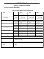
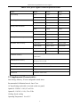
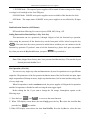
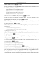
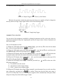
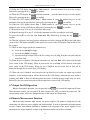
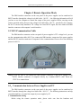
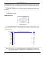
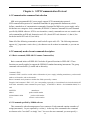
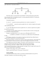
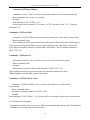
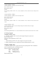
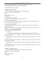
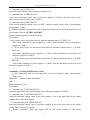
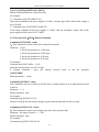
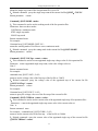
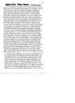
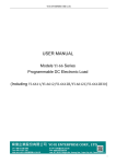
USER’S GUIDE
Programmable DC power supplier
Models M88XX Series
(Including M8811/M8812/M8813/M8851/M8852/M8853)
Nanjing Maynuo Electronics Co., Ltd
Content
Chapter 1 Introduction....................................................................................................................... 2
Chapter2 Technical Specifications .................................................................................................... 3
2.1 Main Technical Specification ........................................................................................................................ 3
2.2 Supplemental Characteristics ........................................................................................................................ 4
2.3 M88XX Power Suppliers Dimension............................................................................................................ 5
Chapter 3 Quick Start ........................................................................................................................ 6
3.1 Front-panel and Rear-panel ........................................................................................................................... 6
3.2 Preliminary Checkout.................................................................................................................................... 7
3.3 If the Power supplier Does Not Turn On....................................................................................................... 7
3.4 How to Adjust the Carrying Handle .............................................................................................................. 8
3.5 How to Rackmount the Instrument ............................................................................................................... 8
Chapter 4 Panel Operation .............................................................................................................. 10
4.1 Key Layout.................................................................................................................................................. 10
4.2 Front-panel Operation Overview................................................................................................................. 11
4.3 Constant Voltage Operation......................................................................................................................... 12
4.4 Constant Current Operation......................................................................................................................... 12
4.5 Saving and Recalling Operation.................................................................................................................. 12
4.6 Menu Operation........................................................................................................................................... 13
4.6.1 Menu Description ............................................................................................................................. 13
4.6.2 Menu Function ................................................................................................................................. 15
4.7 Output On-Off Operation ............................................................................................................................ 21
4.8 Remote Measurement Function................................................................................................................... 21
4.9 Milliohmmeter Function.............................................................................................................................. 22
4.10 Voltmeter Function .................................................................................................................................... 23
Chapter 5 Remote Operation Mode................................................................................................ 24
5.1 M-131Communication Cable ...................................................................................................................... 24
5.2.Communication between Power Supplier and PC.................................................................................... 24
Chapter 6
SCPI Communication Protocal .................................................................................. 26
6.1 Communication command introduction ...................................................................................................... 26
6.2 Commomly used relevant command description ........................................................................................ 26
6.2.1 Basic command (IEEE-488.2 Common Command Set) .................................................................. 26
6.2.2 Command specified by M8800 software.......................................................................................... 26
6.2.3 Measurement Command................................................................................................................... 28
6.2.4 Setting Command ............................................................................................................................. 29
6.2.5 List Operation(LIST)Related Command..................................................................................... 32
Quick Reference ................................................................................................................................ 35
1
M88XX Series Programmable DC Power Suppliers
Chapter 1 Introduction
M88XX Series power suppliers are high performance single-output programmable DC power
suppliers with communication interface, possessing the character of fast rise time speed (The rise
speed of M8811 power supplier can be less than 10mS and that of M8851 can be less than 20mS)
The combination of bench-top and system features in these power suppliers provides versatile
solutions for your design and test requirements. The M88XX Series can not only be programmed
through the keyboard on the panel, but also be functioned as voltmeter and milliohmmeter, which
will bring great convenience to the users. As a regeneration product of ordinary programmable
power suppliers, M88XX Series power suppliers are more cost-effective.
M88XX Series power suppliers’ features
• Low Periodic And Random Deviation (PARD) and noise
• High resolution and accuracy (0.1mV/0.01mA)
• Installing a high-accuracy 5 1/2 voltmeter and milliohmmeter
• Supporting high-accuracy and dynamic programming output
• High –luminance VFD screen and two lines& four ways display
• Smart fan will be automatically initiated according to the temperature.
• Supporting remote voltage compensation and multidata storage
• Supporting external trigger input and output.
• Power-on-self-test,software calibration and standard designed instrument stand
• Supporting GPIB/RS232/RS485/USB application
2
Nanjing Maynuo Electronics Co., Ltd
Chapter2 Technical Specifications
2.1 Main Technical Specification
M881X Series power suppliers technical specification table
Model
Input Rating
Load Regulation
Setting Value Resolution
Readback Value Resolution
Setting Value Accuracy
Readback Value Accuracy
Periodic And Random Deviation
Voltmeter Accuracy
Milliohmmeter Accuracy
M8811
M8812
M8813
Voltage
0-30V
0-75V
0-150V
Current
0-5A
0-2A
0-1A
Voltage
<0.01%+0.5mV
<0.01%+0.5mV
<0.01%+0.5mV
Current
<0.01%+0.1mA
<0.01%+0.1mA
<0.01%+0.1mA
Voltage
0.5mV
1mV
2mV
Current
0.1mA
0.05mA
0.01mA
Voltage
0.1mV
0.1mV
1mV
Current
0.01mA
0.01mA
0.01mA
Voltage
0.01%+2mV
0.01%+5mV
0.01%+15mV
Current
0.05%+1mA
0.05%+0.5mA
0.05%+0.1mA
Voltage
0.02%+5mV
0.02%+12mV
0.02%+25mV
Current
0.1%+5mA
0.05%+2mA
0.05%+1mA
Voltage
3mvp-p
5mvp-p
10mvp-p
Current
2mA rms
1mA rms
0.5mA rms
0-12V Accuracy: 0.02%+2mV;
0-50V Accuracy: 0.02%+5mV
10W. 0-1000mΩ Accuracy: 0.2%+3 mΩ; 1000-10000 mΩ
Accuracy: 0.2%+6 mΩ
0-40℃;
Working Condition
0-90% RH
Power Required
AC 110V/220V+10%; 50/60 HZ
Weight
9Kg
Dimension
108X214X365mm
3
M88XX Series Programmable DC Power Suppliers
M885X Series power suppliers technical specification table
Model
M8851
M8852
M8853
Input Rating
0-6V
0-30V
0-75V
0-60A
0-20A
0-8A
<0.01%+1mV
<0.01%+1mV
<0.01%+1mV
<0.01%+0.1mA
<0.01%+0.1mA
<0.01%+0.1mA
0.1mV
0.5mV
1mV
1mA
0.5mA
0.2mA
0.1mV
0.1mV
0.1mV
0.1mA
0.1mA
0.1mA
0.01%+1mV
0.01%+5mV
0.01%+10mV
0.05%+6mA
0.05%+2mA
0.05%+1mA
0.02%+2mV
0.02%+5mV
0.02%+12mV
0.05%+30mA
0.05%+15mA
0.05%+8mA
3mvp-p
5mvp-p
7mvp-p
15mA rms
7mA rms
4mA rms
0-12V
0.02%+2mV;
0-50V
Load Regulation
Setting Value Resolution
Readback Value Resolution
Setting Value Accuracy
Readback Value Accuracy
Periodic And Random Deviation
Voltmeter Accuracy
Milliohmmeter Accuracy
Accuracy:
Accuracy:
0.02%+5mV
10W. 0-1000mΩ Accuracy: 0.2%+3 mΩ;
Accuracy: 0.2%+6 mΩ
Working Condition
0-40℃;
Power Required
AC 110V/220V+10%; 50/60 HZ
Weight
28Kg
Dimension
0-90% RH
428X103.5X453.5mm
2.2 Supplemental Characteristics
State Storage Memory: 50 user-configurable stored states
Recommended Calibration Interval: Once/ Year
AC Input Ratings (selectable via switch on the rear panel)
Option 01: 220VAC ± 10%, 47 to 63 Hz
Option.02: 110 VAC ± 10%, 47 to 63 Hz
Cooling: forced cooling
Operating Temperature:0 to 40 °C
4
1000-10000 mΩ
Nanjing Maynuo Electronics Co., Ltd
Storage Temperature:-20 to 70 °C.
Environmental Conditions:Designed for indoor use with pollution degree 2 environment. Designed
to operate at maximum relative humidity of 95%.
2.3 M88XX Power Suppliers Dimension
The dimension of M881X Series is 256mmW x 108mm H x 365mm L. Please refer to the
following figure:
Figure 2.1: M881X Power Suppliers Dimension Figure
The dimension of M885X Series is 428mmW×103.5mmH×453.5mmL,Please refer to the
following figure:
Figure 2.2: M885X Power Suppliers Dimension Figure
5
M88XX Series Programmable DC Power Suppliers
Chapter 3 Quick Start
This chapter mainly focuses on the brief introduction of the surface appearance and basic
functions of M88XX Series power suppliers so that both experienced and inexperienced users can be
acquainted with the new products quickly. Meanwhile, the chapter also clarifies some preliminary
checkout that should be made prior to operation to make sure the normal running of the products.
3.1 Front-panel and Rear-panel
The front panel layout of M881X Series power supplier is as follows:
Picture 3.1: The Front Panel of M881X Series Power Suppliers
The upper half is black VFD display screen and knob
The bottom half, left side to right side, is Numberic keys 0-9, ESC key, Function keys,
Up-Down keys, Enter key, Input terminall and Output terminal.
The rear-panel layout of M881X is as follows:
Picture 3.2: The Rear Panel of M881X Series Power Suppliers
① Cooling Window
② Multifunction Interface Connector
6
Nanjing Maynuo Electronics Co., Ltd
③ 9 Pin COM Interface
④ Power Switch Key (110V / 220V)
⑤ Power Socket
3.2 Preliminary Checkout
The following steps help you verify that the power supplier is ready for use
1. Check the list of supplied items
Verify that you have received the following items with your power supplier. If anything is
missing, contact your nearest Sales Office.
□ One power cord for your location
□ The user’s manual
□ One CD
□ One certification of approval
□ One communication cable (only when you have bought communication accessories)
□ One testing line
2.Connect the power cord and turn on the power supplier.
When you turn on the power supplier, the VFD display screen will light up briefly and the
power supplier performs its power-on self-test. Please check if there is any stroke loss on VFD
display.
Warning:The power supplier is shipped from the factory with a power-line cord that has a
plug appropriate for your location. Your power supplier is equipped with a 3-wire grounding
type power cord. The power supplier is grounded only when the power-line cord is plugged
into an appropriate receptacle. Do not operate your power supplier without adequate cabinet
ground connection.。
3.3 If the Power supplier Does Not Turn On
Use the following steps to help solve problems you might encounter when turning on the
instrument.
1. Verify that there is AC power to the power supplier.
First, verify that the power cord is firmly plugged into the power receptacle on the rear panel of
the power supplier. You should also make sure that the power source you plugged the power supplier
into is energized. Then, verify that the power supplier is turned on.
7
M88XX Series Programmable DC Power Suppliers
2. Verify the power-line voltage setting.
The line voltage is set to the proper value for your country (110VAC or 220VAC) when the
power supplier is shipped from the factory. Change the voltage setting if it’s not correct.
3. Verify that the correct power-line fuse is installed.
If the fuse was damaged, please see the table below to replace the fuse for your power supplier.
Model
Fuse Description(110VAC)
Fuse Description(220VAC)
M8811
T5A 250V
T3.15A 250V
M8812
T5A 250V
T3.15A 250V
M8813
T5A 250V
T3.15A 250V
M8851
T10A 250V
T6.3A
250V
M8852
T10A 250V
T6.3A
250V
M8853
T10A 250V
T6.3A
250V
4. How to replace the power-line fuse
Open the plastic cover which locates at below the power input socket in the rear panel of the
power suppliers by screwdriver, then you will see the fuse. Please replace the damaged fuse with the
matched fuse.
3.4 How to Adjust the Carrying Handle
To adjust the position, grasp the handle by the sides and pull outward. Then, rotate the handle to
the desired position. There are following three positions for you to choose:
Picture 3.3 M88XX Series Power Suppliers Viewing Positions
3.5 How to Rackmount the Instrument
8
Nanjing Maynuo Electronics Co., Ltd
The power supplier can be mounted in a standard 19-inch rack cabinet and be easily applied to
your testing system. If you want to rackmount the M88XX Series, please buy MR01 rack kit.
Note:Remove the carrying handle, the rubber coating, and the foot on the rear panel before
rackmounting the instrument.
Picture 3.4: To Rackmount a Single Instrument
Picture 3.5 To Rackmount Two Instruments Side by Side
9
M88XX Series Programmable DC Power Suppliers
Chapter 4 Panel Operation
This chapter mainly introduces the front-panel operation in detail from the following parts:
Voltage Set Operation
Current Set Operation
Saving and Recalling Operation
Menu Operation
Output ON/OFF Operation
Remote Measurement Function
Milliohmmeter Function
Voltmeter Function
4.1 Key Layout
Function Keys
Multifunction Keys
Picture 4.1 Operation Panel Picture
Multifunction Keys Directions
0~9
Numberic keyss
Menu
Menu operation key
List
List output operation
Trigger
Trigger key
V/mΩ
Voltmeter and milliohmmeter switch button
0.1W
Choosing 0.1W power output operation when the instrument is used as
10
Nanjing Maynuo Electronics Co., Ltd
milliohmmeter
1W
Choosing 1W power output when the instrument is used as
milliohmmeter
10W
Choosing 10W power output when the instrument is used as
milliohmmeter
Local
Local operation
Esc
Esc key (can be exited from any working condition)
Function Keys Direction
V-set
I-set
Save
Setting the voltage value
Setting the maximum current value
Saving the current settings to a particular storage locations
Recall
Recalling the saved settings
Menu
Menu operation: setting the parameter
On/Off
Shift
Control the output state
Used together with multifunction key to perform diversity functions and
applications(for example: shift+Menu can perform menu function)
▲
Up-key: choosing menu item in menu operation or to increase the output
voltage
▼
Down-key: choosing menu item in menu operation or to reduce the output
voltage
Enter
Confirm key
4.2 Front-panel Operation Overview
The following section describes an overview of the front-panel keys before operating your
power supplier.
The power supplier is shipped from the factory configured in the front-panel operation mode.
At power-on, the power supplier is automatically set to operate in the front-panel operation mode.
When in this mode, the front panel keys can be used.
When the power supplier is in remote operation mode, you cannot use the front-panel. A change
between front-panel and remote operation modes will not result in any change in the output
parameters. You can change the front-panel and remote operation modes by PC.
The output of the power supplier can be enabled or disabled from the front panel by pressing
11
M88XX Series Programmable DC Power Suppliers
the key On/Off .
The VFD display shows the current operating status of the power supplier with annunciators.
When it is powered on, the VFD will display two lines of data. The first line shows the actual
voltage value, actual current value and power supplier’s status while the second line shows the
voltage value that can be measured by voltmeter and output setting value of the M88XX Series
power suppliers.
4.3 Constant Voltage Operation
The constant voltage range is from 0V to the maximum voltage value of each model. It is very
easy for you to set the constant voltage output.
Solution One:Press the ▲ and ▼ keys to change the value when the M88XX Series power
suppliers are powered on.
Solution Two: Step1. Power on the M88XX series instrument.
Step2. Press
V-Set
key.
Step3. Press the numeric keys 0 to 9 to enter the voltage value you wanted.
Step4. Press
to confirm the value
Enter
Close knob lock function when you in config menu,also can use following two operations:
1) Use upper revolving encoder directly to adjust voltage;
2) Press V-set button then use upper revolving encoder to adjust voltage
4.4 Constant Current Operation
The constant current output range is from 0A to the maximum current value of each type. It is
very easy for you to set the constant current output.
Step1. Power on the M88XX series instrument
Step2. Press
I-Set
key
Step3. Use the numeric keys
Step4. Press
Enter
0
to
9
to enter the voltage value you wanted.
key to confirm the value
IF you close knob lock function in config menu,can use following operation:
Press V-set button then use upper revolving encoder to adjust voltage
4.5 Saving and Recalling Operation
You can store up to 50 different output states in storage register locations so that you can recall
the saved settings quickly. This kind of store operation can be performed by the keys
12
Save
and
Nanjing Maynuo Electronics Co., Ltd
Recall
located in the front panel. When the fast recalling is activated, you can press the numberic
keys 0 to 9 to invoke the corresponding data.
Each output state includes 1. Constant voltage value, 2.Constant current value, 3.Maximun
voltage setting value, 4.Maximum output voltage value.
Step1. After you setting an output state (CV value, CC value and Maximum voltage), press the
key
Save
Step2.Use the numeric keys
0
to 9
or ▲ and ▼ keys to select the memory location (the
range is 1 to 50) which you want to store in.
Step3. Press
Enter
to confirm the memory location.
Step4. Press
Recall
key.
Step5. Use numeric keys
to
0
9
or ▲ and ▼ keys to select the states which you want
to recall.
Step6. Press
Enter
key to confirm. Then the saved settings will come out
4.6 Menu Operation
4.6.1 Menu Description
Press the key
MENU
to access to the menu function and at the moment theVFD display
screen shows the menu items. You can select the menu items by pressing the ▲ and ▼ keys or by
rotating the knob, and then press the key
press the key
Esc
ENTER
to enter in the menu item you wanted. Or you can
to get back to the higher level menu.
The first level menu includes:
Config
System set
List Set
Auto test
Output Timer
When accessing to Config item,the following menu items will be displayed on the VFD
display screen by pressing the keys ▲ and ▼.
Init:All set for factory value
On
Output Recall:
Off(Default)
Setting the output to OFF state when the
power supplier is powered on.
Setting the same state as last time you turned
off the power supplier.
13
M88XX Series Programmable DC Power Suppliers
The buzzer will sound when any key was
pressed.
the buzzer will not sound when any key was
pressed
On(Default)
Key Sound Set:
Off
On
Knob Lock Set:
Flemote Meas.:
Current Unit Set:
Match Power:
Baudrate Set:
The knob is locked and rotating the knob will not
cause any change of the setting value.
Off(Default) The knob is unlocked and rotating the knob will
cause change of the setting value.
On
Activating the remote meas. mode
( Rear-panel meas. mode)
Off(Default) Activating the front-panel meas. mode
mA
A(Default)
Current unit mA
Curren unit A (Default)
50HZ
Off(Default)
Match 50HZ (50HZ Default)
Match 50HZ
4800
9600(Default)
19200
38400
Setting the baudrate as 4800bps
Setting the baudrate as 9600bps
Setting the baudrate as 19200bps
Setting the baudrate as 38400bps
Comm. Parity:
None(Default) Setting no parity bit
Even
Setting comm. parity as even parity bit
Odd
Setting comm. parity as odd parity bit
Port Mode:
Trigger(Def)
RI/DFI
Digital I/O
Key Lock Set:
Password=
Trigger mode
Digit port
Entering password and then pressing the key
Enter to unlock the password
Exit:
When accessing to System Set item,the following menu items will be displayed on the VFD
display screen by pressing the keys ▲ and ▼.
Max Volt. Set:
Max=
Setting the maximum output voltage
14
Nanjing Maynuo Electronics Co., Ltd
Step=
Step Volt Set:
Inputting the voltage step value and pressing
up-down keys to change it
Exit
When accessing to the List Set item,the following menu items will be displayed on the VFD
display screen by pressing the keys ▲ and ▼.
Load List File: Read list
Edit List File:
Edit File Format:
Exit:
Continuous
Continuous mode: once:; repeat
Step
Single-step mode, once: repeat:
8X25 Steps
Setting list file as 8X25step
4X50 Steps
Setting list file as 4X50step
2X100 Steps
Setting list file as 2X100 step
1X200 Steps
Setting list file as 1X200 step
When accessing to the List Set item,the following menu items will be displayed on the VFD
display screen by pressing the keys ▲ and ▼.
Load Atest File:
Edit Atest File:
Exit:
Timer State
ON
Off(Default)
Timer Set
Timer=
Activating output timer
Closing output timer
Inputting the time
Note: When accessing to the menu item, you can press Esc
to exit the menu operation.
No matter which function the instrument is performing, you can exit the function
operation status by pressing the key Esc .
4.6.2 Menu Function
Initiating the Output State (>Output Setup)
15
M88XX Series Programmable DC Power Suppliers
This instruction can initiate the output state when the power supplier is powered on. If you
select the item On, the power supplier will initiate the output to OFF state when the power supplier
is powered on. If you select the item Off, the output will remain the same state as last time you
turned off the power supplier
Setting the Key Sound (Key Sound Set)
This instruction can switch on/off the buzzing sound when you press any key, If you select the
item On, the buzzer will sound when any key was pressed. If you select Off, the buzzer will not
sound when the keys were pressed. Default setting is the item On; the buzzer will sound when you
press any key.
Fast Recalling Function (>Fast Recall)
This instruction can help you recall the saved data very fast when it is set as On condition. The
detailed operations are as follows: first you need to save several often used voltage value and current
value, then use the Recall key to recall those data.
Press the keys
and
Shift
MENU
screen shows the item Config, press the key
to access to the menu function. When VFD display
ENTER
to confirm。
Press the keys▲ and ▼to select the item Fast Recall, and then confirm by pressing the key
ENTER
.
Press the keys▲ and ▼to select the item On.
Press the key
ESC
Press the keys
twice to exit the menu operation.
V-set
and
I-set
to set your favored voltage value and current value.
After you setting an output state (CV value, CC value and Maximum voltage), press the
key
Save
Use the numeric keys
0
to
9
or ▲ and ▼ keys to select the memory location (the range
is 1 to 50) which you want to store in.
. Press
Enter
. Press
Recall
key to confirm the memory location.
key.
Use numeric keys 0
to 9
or ▲ and ▼ keys to select the states which you want to
recall.
. Press
Enter
key to confirm. Then the saved settings will come out
Overcurrent Protection (>OCP Set)
16
Nanjing Maynuo Electronics Co., Ltd
M8811, M8812, M8813, M8851, M8852, M8853 are not available of this function for while.
Setting the Baudrate (>Baudrate Set)
This instruction can change the communication baud rate of the power supplier; the baud rate
range is 4800bps,9600bps,19200bps,38400bps. Before the communication, you must make sure
that there is same baud rate between the power supplier and the host computer. Default baud rate is
9600bps.
Setting Address (>Sour. Address)
This instruction can set the communication address of each power supplier. The address range is
from 0 to 30。Before the communication, you must make sure that there is same address between the
power supplier and the host computer. Default address is 0.
Operation steps:
Press the keys
Shift
and
MENU
to access to the menu function. When the VFD display
screen shows the item Config., press the key
ENTER
to confirm.
Press the keys ▲ and ▼to get the item Sour. Address,then press the key
ENTER
to confirm.
When the VFD display screen shows Address=**, choose the number keys from 0
to set the address, followed by pressing the key
Press the key
ESC
ENTER
to
to confirm.
twice to exit the menu operation.
Port Mode (>Port Mode):
M8811, M8812, M8813, M8851, M8852, M8853 are not available of this function for while.
Trigger Operation (Shift+Trigger)
Just as described above, the trigger operation can also be applied to the list output operation.
There are three trigger modes for the power supplier. Before performing the trigger function,
users need to select one trigger mode.
Trigger by keyboard (pressing the keys
initiated once when pressing the keys
Shift
Shift
and Trigger ):The trigger operation will be
and Trigger under the condition that the trigger by
keyboard is effective.
Remote Control Function (>Output Contr.)
There are three modes under the remote control function: LATCHED、FOLLOW、OFF.
17
9
M88XX Series Programmable DC Power Suppliers
LITCHED Mode:The output of power supplier will be turned off when testing out the change
in voltage level from high to low from TRQ port.
FOLLOW Mode:M88XX series power suppliers are not available of this function for while.
OFF Mode:The output status of M88XX series power suppliers are not affected by RI input
level.
Fault Indication Function (>DFI Status)
DFI results from following five sources: Quest, OPER, StEV, Requ., Off.
Setting Password for Function Keys (>Key Lock Set)
This instruction can set a password (1 through 4 digits) to lock the function keys operation.
After setting the password, all the function keys on the front panel will be locked except the key
On/Off
. You must enter the correct password to unlock them, and then you can continue to do the
function key operation. If you don’t want to lock the function keys, please don’t press any number
key when you enter the Key Lock Set item, just press
Enter
key to unlock it.
Note: When shipped from factory, there is no password and function keys. The start bit of your
desired password shouldn’t be 0.
List Operation (>List Set)
You can set every single-step value and duration time by new list operation so as to get different
output list. The parameters of the list operation include the name of the list file which are input, input
single-step numbers (200steps at most), single-step duration time (1mS at least) and the setting value
of every single-step.
When list operation is under continuous mode, the power supplier will begin the list operation
until the list operation is finished or until receiving the next trigger signal.
Before editing the list, if you want to change the file storage format,please operate as the
following steps:
1) Press the keys Shift
and
Menu
to access to the menu function.
2) When VFD display screen shows the item Config, press the key ▼to select the item List Set,
press the key Enter to confirm.
3) When VFD display screen shows the item Load ListFile, Press the key▼twice, select the item
18
Nanjing Maynuo Electronics Co., Ltd
Edit File Format, press the key
Enter
to confirm.
4) When VFD display screen shows 8*25 Steps, Press the key▼twice, select a list mode you want
from 1*200 Steps,2*100 Steps, 4*50 Steps.
2*100 Steps means to set a two100 steps of list file.
1*200 Steps means to set a one 200steps of list lie..
8*25 Steps means to set an eight 25 steps of list file.
4*50 Steps means to set a four 50 steps of list file.
5) Press ▼ to select the item Edit List File, press the key Enter to confirm.
6) When VFD display screen show the item Edit List File 1,press the key ▲ and ▼ to select
sequential number you want to edit, press the key Enter to confirm.
7) When VFD display screen show the item List x Steps=
xxx,press numberic keys to set the total
list steps(x). Press the key Enter to confirm.
8) When VFD display screen show the item List File x Loop Mode, press the key ▲ and ▼ to select
operation mode:
Loop Mode means to looping execute list file
Continuous means to execute all steps in the list file once a triggle
Step Mode means one triggle one step
9) When VFD display screen show the item Step 1 Time= xxxxx mS, press numberic keys to set time
for step 1, press the key Enter to confirm.
10) When VFD display screen show the item Step 1 Volt= xxxxx V, press numberic keys to set
voltage, press the key Enter to confirm.
11) When VFD display screen show the item Step 1 Curr= xxxxx A, press numberic keys to set
current, press the key Enter to confirm.
12) Repeat step 9, 10, 11 to complete all steps in list file
13) Repeat step 5 to 15 to edit other list files if needed
14) Press ▼ to select Load List File, press the key Enter to confirm.
15) Electronic load is in the LIST MODE. VFD display screen shows OFF in the right when output
is on. VFD display screen shows List1 in the right when output is off. Press key On/Off to execute.
Press key Shift+2 or Esc to exit. Press key Shift+2 direct to excute the last list file.
16) Under loop mode, electronic load looping executes automatically. Please find the following table
19
M88XX Series Programmable DC Power Suppliers
at Continuous Mode and Step Mode.
Picture 4.2 Repeat Trigger with 2 Times Cyclical Pattern
When the list operation is under the single step mode, the power supplier will not be changed to
next step until receiving a trigger signal. Please refer to the following picture
Picture 4.3 Single-Step Trigger
Automatic Test (>Atest Set)
You can check if the equipment is qualified by editing the automatic test files, such as the value set,
comparison parameters, delay time, inputting the step No.(50 steps at most). 4 data of automatic test
files can be edited.
How to edit automatic test files
17) When the VFD display shows the item Menu Config,press the key ▼to select the item Atest
Set,followed by pressing the key Enter to confirm.
18) When the VFD display shows the item Load Atest File,press the key▼ twice and choose the
item Edit List File, followed by pressing the key Enter to confirm.
19) When the VFD display shows the item Edit Atest File 1,press the keys
and ▼ and select the
Enter
sequential number that need to be edited, followed by pressing the key
to confirm.
20) When the VFD display shows Atestx Steps= xxx,press the numeric keys to set the steps of list
files, followed by pressing the key Enter to confirm.
21) When the VFD display shows Step 1 Test Curr, press the keys
and ▼ to select one of the
following testing types:
a) Curr means to test the current.
b) Volt means to test the output voltage.
c) DVM means to test voltmeter input.
22) When the VFD display shows Step 1 Time= xxxxx S,press the numeric keys to set the test delay
time, followed by pressing the key Enter to confirm. Please note that the delay time range is
0.2S-25.5S. If delay time is set as 25.5S, the power supplier will be automatically in the pause mode
and go on testing only when another trigger is input.
20
Nanjing Maynuo Electronics Co., Ltd
23) When the VFD display shows Step 1 Volt= xxxxx V,press the numeric keys to set the voltage,
followed by pressing the key Enter to confirm.
24) When the VFD display shows Step 1 Curr= xxxxx A, press the numeric keys to set the current,
followed by pressing the key Enter to confirm.
25) When the VFD display shows Step 1 Max= xxxxx X,press the numeric keys to set the
maximum value for the qualified test, followed by pressing the key Enter to confirm.
26) When the VFD display shows Step 1 Min= xxxxx X,press the numeric keys to set the
minimum value for the qualified test, followed by pressing the key Enter to confirm.
27) Repeat from step 21 to step 26 to set all the other steps.
28) Repeat from step 18 to step 27 to edit other automatic test files according to your need.
29) Press the key▼ to select the item Load Atest File, followed by pressing the key Enter to
confirm.
30) Then the electronic load enter into the automatic test mode, showing AUTO1 at the right upper
corner of the VFD display and OFF at the right lower corner of the VFD display. That means to wait
for a trigger.
31) There are three trigger modes for automatic test
d) Press the key On/Off to trigger.
e) Press the key Shift+3 to trigger.
f) Become the high voltage level to the low voltage level by Trig_in at the rear panel and last
more than 5mS.
32) When the power supplier is having the automatic test, the word Wait will be showed at the right
lower corner of the VFD display. When in pause mode, the word Stay will be showed at the right
lower corner of the VFD display. When one test is finished, the test result Pass or Fail will be
showed at the right lower corner of the VFD display.
33) When one test is finished, users can press the up-down keys to make one single step worked
manually. At the moment, step n will be showed on the VFD display, indicating the step which is
working; then Han is showed, indicating that the load is in hand-operated single step test state,
followed by the test results being showed at the right lower corner of the VFD display.
4.7 Output On-Off Operation
When in front-panel operation, you can press the key On/Off to control the output on-off state.
When in remote control, you can send SCPI order(Output: ON | OFF)to control the output sate. The
current setting values will not be changed because of the output on-off operation.
4.8 Remote Measurement Function
When the load consumes high current, the power supplier will produce voltage drop in the
connecting wire between power supplier and load terminals. In order to guarantee the measurement
accuracy, remote measurement terminals is installed at the rear-panel of the power supplier. Users
can measure the output terminals voltage of the instrument under test by these terminals.
21
M88XX Series Programmable DC Power Suppliers
Before performing the remote measurement function, you need to set the power supplier as the
remote measurement mode.
Please refer to the picture 4.4 for the trigger terminals and measurement terminals.
Piccture4.4 Remote Measurement Terminals
-S and +S are remote measurement terminals; TRQ and TRI are trigger terminals,the last two
terminals are ground terminals.
The output of power supplier will be turned off when testing out the change in voltage level
from high to low from TRQ port which is under the latched mode of the remote control function. As
a multifunction extended port, TRI port is designed for future expanded.
4.9 Milliohmmeter Function
Source Meter provides the four-line electrical resistance measurement,just as showed in
following picture 4.5, which can measure accurately the low resistance and the maximum
measurement resistance is 10Ω。In order to avoid the damage of the resistance under test, please
make sure the resistance under test is within the measurement rang.
Three measurement ranges can be optional: 0.1W、1W、10W。
Operation Method
1) Press the keys Shift
to measure the resistance.
2) Press the keys
Milliohmmeter.
Shift
and V/m Ω (VFD display screen shows----, --m Ω ,Range:0.1W)
and 0.1W or 1W or 10W to set different measurement range of
Picture 4.5 Milliohmmeter Measuring Electrical Resistance
22
Nanjing Maynuo Electronics Co., Ltd
4.10 Voltmeter Function
The voltage of the instrument under test can be measured if the wires are connected together
just as the picture 4.6.
Picture 4.6 Measuring the Voltage of the Instrument under Test
23
M88XX Series Programmable DC Power Suppliers
Chapter 5 Remote Operation Mode
The DB9 interface connector on the rear panel of the power supplier can be transferred to
RS232 interface through the voltage level shift cable(M-131), the following information will tell
you how to use the computer to control the output of the power supplier. Before carrying out the
remote operation mode, please use the voltage level shift cable(M-131)provided by our company,
for M-131 can not only transform TTL voltage level into RS232 signal, but also connect the DB9
interface connector with computer’s serial interface..
5.1 M-131Communication Cable
The DB9 interface connector on the rear panel of power supplier is TTL voltage level; you can
use the communication cable (M-131) to connect the DB9 interface connector of the power supplier
and the RS-232 interface connector of computer for the communication. Please refer to the following
picture for M-131.
Picture 5.1 M-131
Note:It will not work if you connect the DB9 interface connector of the power supplier to the
RS232 interface connector of computer directly by a standard RS232 cable. Please use
IT-E131 to connect them.
5.2.Communication between Power Supplier and PC
The DB9 interface connector on the rear panel of the power supplier can be transferred to
RS232 interface through the voltage level shift cable(M-131). The following instructions can help
you understand how to control the output of power supplier by PC.
1. Communication Setting
Before using the remote operation mode, please make sure that the baudrate and
24
Nanjing Maynuo Electronics Co., Ltd
communication address in power supplier are the same as that in the computer software; otherwise,
the communication will fail. You can change the baud rate and communication address from the
front panel or from computer.
(1) Baud rate: 9600(4800, 9600, 19200, 38400, which are selectable from the menu on the
front-panel.)
(2) Data bit: 8
(3) Stop bit: 1
(4) Parity: (none, even, odd)
2. DB9 Serial Interface
DB9 Serial Interface
The output of DB9 interface on the rear-panel of the power supplier is TTL voltage level, so the
voltage level shift cable(M-131) must be applied before connecting the DB9 interface with the
serial interface on PC.
Power Supplier
VCC
RXD
TXD
NC
GND
NC
NC
NC
NC
M-131 Voltage Level Shift Cable
1
2
3
4
5
6
7
8
9
PC
1
2
3
4
5
6
7
8
9
VCC
RXD
TXD
DTR
GND
NC
RTS
NC
NC
Note:It will not work if you connect the DB9 interface connector of the power supplier to the
RS232 interface connector of computer directly by a standard RS232 cable. Please use
IT-E131 to connect them.
25
M88XX Series Programmable DC Power Suppliers
Chapter 6 SCPI Communication Protocal
6.1 Communication command introduction
M88 series programmable DC power supply support SCPI communication protocol.
SCPI communication protocol is a standard commands for programmable iInstruments, which
defines a standard set of communication commands.Command for M88 series power supply can be
divided into two categories: basic commands (IEEE-488.2 Common Command Set) and command
specified by M8800 software. SCPI is case-insensitive, namely commands are not case sensitive and
each command has an EOI end: Instruction end <LF> (that ASCII code character ' n', that is, line
breaks decimal ASCII code 10, hex 0x0A).
Note: All of the following commands to send back all require add <LF>. The following statement
appears in [:] represents a semi-colon (:), the character can be written in commands, or you can not
write.
6.2 Commomly used relevant command description
6.2.1 Basic command (IEEE-488.2 Common Command Set)
Basic command inclues all IEEE-488.2 includes all general functions in IEEE-488.2. These
functions are usually applied to support the IEEE488.2 standard measuring instruments. The group
command with an asterisk (*) started and no hierarchy.
Command * IDN?
Command * IDN is used for read the relative information of power supply, including manufacture, product model
number, serial number, and version number.
Return command: return parameter contains four fields separated by commas.
Example: Send command * IDN? <LF>, the corresponding expressed as a hexadecimal is 0x2A 0x49 0x44 0x4E
0x3F 0x0A. meanwhile, return command for power supply
is MAYNUO,M8812,881201096006118000, V1.0
And
MAYNUO
M8812
881201096006118000
V1.0
manufacture
product model number
product serial number
software version number
6.2.2 Command specified by M8800 software
This command is ordered arrangements of tree constructs. Each command contains a number of
strings (mnemonic) . Layers separated by a colon (:). At the top of the command in the command
tree known as the "root shell" or simply "root." Access to the next command, you must specify a
26
Nanjing Maynuo Electronics Co., Ltd
path. Ordered tree is structured as follows:
In the above table: AA represents the root path; BB, CC, DD represents the root path of the
direct sub-path. EE, FF, GG said that the path is a sub-sub-path under the BB. HH, JJ said that the
path is a sub-sub-path under DD.
Command description:
1) [:] AA: CC
means the current root path for the AA, visit the AA under the CC.
2)[:] AA: BB: FF
means the current root path for the AA, visit the AA path to the root path
of the sub-BB under the FF.
3) [:] AA: DD: HH means the current root path for the AA, visit the AA path to the root path of
the sub-DD under the HH.
Command specified by M8800 software also can send more than one order in a message and
use a semicolon (;) between each order.
Example: [:]AA:BB:EE;FF;GG+<LF> means access to BB under the EE, FF, GG.
[:]AA:BB:FF;:AA:DD:HH+<LF> means access to BB under the FF and DD under
the HH.
SCPI language mnemonic or keywords has a long format and short format. Short format is
actually short for long format. It uses the following rules:
Short format mnemonic is the first four characters of long format mnemonic. If the length of the
long-form mnemonic characters less than or equal 4, then the length of the mnemonic the same.
If the length is greater than the length of 4 mnemonic, and the fourth character is a vowel, short
mnemonic will discard the fourth vowel characters and become the third characters.
Example: short-type mnemonic of ERRor is ERR, rather than rather than the ERRO
Some command needs parameters. Setting command, for example. There is a space (ASCII code is 32)
between the command and the first parameter.
Example: setting voltage value [:] VOLT 12.000<LF>
There is a space (ASCII code is 32) between 12.00 and VOLT
System command
Commands described in this section are [:] SYSTem commands under the root path. The
following Commands are used short-type mnemonic format.
27
M88XX Series Programmable DC Power Suppliers
Command [:]SYSTem:ERRor?
Command [:]SYSTem:ERRor is used to read the power of the error code and error message
Return command: Error Code, error message.
Example:
Send command [:] SYST: ERR? <LF>
Power supply return command: "0, 'No Error'", or "50, 'Error Para Count'", or "70, 'Invalid
Command'" etc..
Command [:] SYSTem: REM
Command [:] SYSTem: REM is used to set remote control mode, that is the PC control mode.
Return command: None
After sending successful, the power has been in the remote control mode when “REM”appears
in the right corner front panel.Otherwise the previous operation is not valid. Please switch to the
power supply front panel controls by pressing Shift + the number 7 key, or send the command [:]
SYST: LOC <LF>.
Command [:] SYSTem: LOC
Command [:] SYSTem: LOC is used to set the power control mode for the panel.
Return command: None
Example:
In the remote control (PC) mode, Send command [:] SYST: LOC <LF> ,
After sending successful, the power has been in the front panel control mode when
“REM”disappears from the right corner of front panel.
Command [:] SYSTem: SENSe <bool>
Command [:] SYSTem: SENSe <bool> is used to check the power is under remote
measurements.
Return command: None
Parameters: bool-type parameters, (0-OFF, 1-ON)
Example:
Send command [:] SYST: SENS 1 <LF>. If successful, Power supply is in the remote measurement.
6.2.3 Measurement Command
Commands described in this section are [:] MEASure commands under the root path. The following
Commands are used short-type mnemonic format.
28
Nanjing Maynuo Electronics Co., Ltd
Command [:] MEASure: VOLTage
Command [:] MEASure: VOLTage is used to read output voltage
Return command: Numerical
Return parameters Unit: V
Example:
Send command [:] MEAS: VOLT? <LF>, if return command is 12.560, it means the current voltage value is
12.560V.
Command [:] MEASure: CURRent?
Command [:] MEASure: CURRent is used to read output current
Return command: Numerical
Return parameters Unit: A
Example:
Send command [:] MEAS: CURR? <LF>, if return command is 1.245, it means the current current value is
1.245A.
Command [:] MEASure: DVM?
Command [:] MEASure: DVM?is used to read input voltage of the voltmeter in the power supply
Return command: Numerical
Return parameters Unit: V
Example:
Send command [:]MEAS:DVM? <LF>, if return command is12.560, it means the current current value is 12.560V.
6.2.4 Setting Command
Command [:] OUTPut <bool>
0. Command [:] OUTPut <bool> is used to set the output of the power to open or not
Return command: None
Parameters: bool-type parameters, (0-OFF, 1-ON)
Example:
Send command [:] OUTP 1<LF>, Power output is set to open if successful.
1. Related command: Query power output status. Return command parameter is <bool>.
Command [:] MODE <mode>
1. Command [:] MODE <mode> is used to select the power operating mode. That is command set
mode or sequential list mode, or milliohmmeter mode。
Parameter: mode has three following modes,
FIXed
command set mode
LIST
sequential list mode
DRM
milliohmmeter mode
Return command: None
29
M88XX Series Programmable DC Power Suppliers
Send command [:] MODE LIST<LF>, the power mode is sequential list mode.
2. Related command: Query power working mode:] MODE?
. Return command parameter: <mode>
Command [:]VOLTage <Value>
1、This command is used to set the voltage value of power suppliers.
Parameters:numerical value|MAX|MIN
Unit:V
Return Command:None
For Example:
1)Command sent [:]VOLT 30<LF>
means the current voltage value of the power supplier is 30V.
2)Command sent [:]VOLT MAX
If the current maximum voltage value of the power supplier is 76.000V,then the current voltage
value is the maximum voltage value, 76.000V.
3)Command sent [:]VOLT MIN
If the current minimum voltage value is 0.000V,then the current voltage value is the minimum
voltage value,0.000V.
2、Related Command:the command used to query the voltage value set, the maximum value set or
the minimum value set[:]VOLT? MAX|MIN
Return command parameters: numerical value
For example:
1)If you want to query the voltage value set, then the command sent is [:]VOLT?+<LF>
If the return command of a power supplier is:10.0000,then the voltage value set of the power
supplier is 10.0000V.
2)If you want to query the maximum voltage value set, then the command sent is:VOLT?
MAX+<LF>
If the return command of a power supplier is:76.0000,then the maximum voltage value set of the
power supplier is 76.0000V.
3)If you want to query the minimum voltage value set, then the command sent is: VOLT?
MIN+<LF>
If the return command of a power supplier is:0.0000,then the minimum voltage value set of the
power supplier is 0.0000V.
Command [:]CURRent <Value>
1、This command is used to set the current value of the power supplier.
Parameters:numerical value|MAX|MIN
Unit:A
Return command:none
For example:
30
Nanjing Maynuo Electronics Co., Ltd
1)Command sent[:]CURR 3<LF>
means the current current value of the power supplier is 3A.
2)Command sent [:]CURR MAX<LF>
If the current maximum current value of the power supplier is 2.0000A,then the current current
value is the maximum current value, 2.0000A.
3)Command sent [:]CURR MIN<LF>
If the current minimum current value is 0.000V,then the current current value is the minimum
current value,0.000V.
2、Related Command:the command used to query the current value set, the maximum value set or
the minimum value set [:]CURR? MAX|MIN
Return command parameters: numerical value
For example:
1) If you want to query the current value set, then the command sent is [:]CURR?<LF>.
If the return command of a power supplier is:1.0000,then the current value set of the power
supplier is 1.0000A.
2)If you want to query the maximum current value set, then the command sent is:[:]CURR?
MAX<LF>.
If the return command of a power supplier is:2.0000,then the maximum current value set of
the power supplier is 2.0000A .
3)If you want to query the minimum current value set, then the command sent is: [:]CURR?
MIN<LF>.
If the return command of a power supplier is:0.0000,then the minimum current value set of
the power supplier is 0.0000A.
Command:[:]VOLTage:PROTection <Value>
1、This command is used to set the upper limit of the power suppliers, that is the maximum
voltage value.
Parameters: numerical value |MAX|MIN
Unit:V
Return command:none
For example:
1)Command sent [:]VOLT:PROT 30<LF>
means the upper limit of the current voltage value of the power supplier is 30.000V.
2)Command sent [:]VOLT:PROT MAX<LF>
means the maximum voltage value of the power supplier is set as the upper limit of the current
voltage value of the power supplier.
3)Command sent[:]VOLT:PROT MIN<LF>
means the minimum voltage value of the power supplier is set as the lower limit of the current
voltage value of the power supplier.
2 、 Related command : query the upper limit of the current voltage of the power
31
M88XX Series Programmable DC Power Suppliers
supplier[:]VOLTage:PROTection? [MAX]
Return command parameters: numerical value
For example:
1)Command sent[:]VOLT:PROT?<LF>
If the return command of the power supplier is 20.000,then the upper limit of the current voltage is
set as 20.000V.
2)Command sent [:]VOLT:PROT? MAX<LF>
If the return command of the power supplier is 76.000,then the maximum voltage value of the
power supplier which can be set is 76.000V.
6.2.5 List Operation(LIST)Related Command
Command[:]LIST:AREA <num>
1、This command is used to set the list location division mode.
Parameter:1|2|4|8
1. Set the list operation as 1*200 steps;
2. Set the list operation as 2*100 steps;
3. Set the list operation as 4*50 steps;
4. Set the list operation as 8*25 steps.
For Example:
Command sent[:]LIST:AREA 8<LF>
means the list operation is set as 8*25 steps.
2. Related command : query the location division
[:]LIST:AREA?
Return parameters:<num>
mode
of
the
list
operation
Command[:]LIST:RCL <num>
This command is used to recall the saved files from a certain location so as to make them executed
in the list.
Parameter:1~8
Return command:none
For example:
Command sent[:]LIST:RCl 2<LF>
Means to recall the list file from the storage register location2 and make the file executed.
Command[:]LIST:COUNt <count>
1、This command is used to set the single step count of list operation files.
Parameter:the range of count is:1~200。
Return command:none
For example:
Command sent[:]LIST:COUN 20<LF>
32
Nanjing Maynuo Electronics Co., Ltd
Means the single step count of the list operation file is set as 20.
2、Related command:query the single step count of the current list files[:]LIST:COUNt?
Return parameter:<count>
Command [:]LIST:MODE <mode>
1、This command is used to set the working mode of the list operation files.
Parameters: there are three modes:
CONTinuous: continuous mode
STEP: single step mode
LOOP: loop mode
Return command: none
For example:
Command sent [:]LIST:MODE CONT<LF>
means the working mode of list files are set as continuous mode.
2、Related command:query the setting mode in the current list files[:]LIST:MODE?
Return parameters:<mode>
Command [:]LIST:VOLTage <count>,<value>
1、This command is used to set one appointed single step voltage value of a list operation file.
Parameter:count is appointed single step count; value is the voltage value set.
Unit: V
Return command: none
For example:
command sent [:]LIST:VOLT 1,5<LF>
means to set the voltage value of the first step of the list file as 5.000V.
2、Related command:query the voltage value of the appointed step of the current list file
[:]LIST:VOLTage? <count>
Return parameters:<value>
For example:
Command sent [:]LIST:VOLT? 1<LF>
means to query the voltage value set of the first step of the current list file.
Command [:]LIST:CURRent <count>,<value>
1、This command is used to set the current value of the appointed single step of list operation files.
Parameters:count is the appointed single step count; value is the current value set.
Unit:A
Return command:none
For example:command sent [:]LIST:CURR 1,2<LF>
means to set the current value of the first step of the list file as 2.000A.
2、Related command:query the current value of the appointed single step of the current list file
[:]LIST:CURRent? <count>
33
M88XX Series Programmable DC Power Suppliers
Return parameter:<value>
For example:
Command sent[:]LIST:CURR? 1<LF>
Means to query the current value set of the first step of the current list file.
Command [:]LIST:WIDTh <count>,<time>
1、This command is used to set the delay time of the appointed single step of the operation files.
Parameters:count is the appointed single step count; time is the delay time set.
Unit:mS
Return command:none
For example:command sent[:]LIST:WIDT 1,2000<LF>
means to set the delay time of the first single step of the list file as 2000mS.
2 、 Related command : query the delay time of the single step of the current list files
[:]LIST:WIDTh? <count>
Return parameters:<time>
Command [:]TRIGger
When the trigger source is set as communication command trigger mode, this command will give out
a trigger signal, which function can also be realized by pressing the keys Shift+3 located in the
front panel. Return command:None
For example:command sent [:]TRIG<LF>
Command [:]TRIGger:SOURce <mode>
This command is used to set the trigger mode of the power supplier.
Parameter:there are three trigger modes.
IMMediate: means the trigger mode is keyboard trigger mode.
EXTernal: means the trigger mode is external signal(TTL voltage level) mode
BUS: means the trigger mode is communication command trigger mode.
Return command:none
For example:command sent [:]TRIG:SOUR IMM<LF>
means the power supplier is set as triggering by the keyboard located in the front panel.
34
Nanjing Maynuo Electronics Co., Ltd
Quick Reference
Safety
Please donot install any spare or repair the instrument without permission. In order to make sure
the normal work of the instrument, please have it mended in the maintenance department designated
by our company.
Pease review the following safety precautions before operating our equipment.
Safety Symbols
Please keep in mind the following items which may result in injuries on your body.
Connect it to safety earth ground using the wire recommended in the user manual.
High voltage danger (Non-professionals are forbidden to open the instrument)
The symbol on an instrument indicates that the user should refer to the operating
Instructions located in the manual.
Certification and Warranty
M881X Series power suppliers meet its published specifications at time of shipment from the
factory.
Warranty
This instrument product is warranted against defects in material and workmanship for a period
of one year from date of delivery.
Maintenance Service
This product must be returned to maintenance department designated by our company for
repairing. Customer shall prepay shipping charges (and shall pay all duty and taxes) for products
returned to the supplier for warranty service. Except for products returned to customer from another
country, supplier shall pay for return of products to customer.
Limitation of Warranty
The foregoing warranty shall not apply to
1. Defects resulting from improper or inadequate maintenance by the Customer,
2. Customer-supplied software or interfacing,
3. Unauthorized modification or misuse,
4. Operation outside of the environmental specifications for the product, or improper site
preparation and maintenance.
5. Defects resulting from the circuit installed by clients themselves
Attention
No inform will be given for any changes in the content of the user’s guide.
35