1
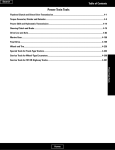
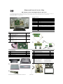
Illustrated Parts & Service Map
HP LT3700 37-Inch LCD High-Definition Television
© 2007 Hewlett-Packard Development Company, L.P. The information contained herein is subject to change without notice. HP shall not be liable for technical or editorial errors or omissions contained herein. Intel, Pentium, Intel Inside, and the Intel logo are trademarks or registered trademarks of the Intel Corporation and its subsidiaries in the U. S. and other countries.
Document Number 454401-001.
1st Edition June 2007
Key Specifications
Resolution
1366 (H) x 768 (V)
Brightness
500 cd/m2
Contrast ratio
1000:1
Viewing angle
178 degrees
Response time
6 ms
Expected lifetime
60,000 hours
Scalar
Trident PX66
Supported input
480i, 480p, 720p, 1080i, 1080p (HDMI only)
Connectivity
AV in (2), Component In (YPbPr) (2), HDMI, (3), S-Video In (2),
Antenna In (1), PC VGA In (1), Analog Audio In (L/R) (5), Pc Audio
In (1), RS-232c (1), USB Port (1), Audio Out (1), SPDIF Out (1)
Speakers
2 x 10W, 1 way
Tuning
ATSC/NTSC/Clear - QAM
Power supply
120 V AC 60 Hz
Power consumption
220W
Panel manufacturer
LPL
Boards
1
Main board assy, including:
- Main board
- Cable: Main board to power supply
455594-001
2
Inverter board assy, including:
- Inverter boards: Master and slave
- Cables: Master and slave
455597-001
3
Control board assy, including:
- Control board
- LVDS cable
- Ribbon cables (2)
455601-001
4
Keypad/Infrared assy, including:
- Keypad buttons
- Keypad PCA board
- Infrared board
- Cable: Main board to keypad
455604-001
2
3
1
Misc parts
Covers/mounting/stand
1
Stand neck assy, including:
- Stand neck
- Repair screw kit
455588-001
1
*
Stand base
452085-001
2
Back cover/bucket
452093-001
3
Mesh bracket board cover
4
5
Power supply assy, including:
- Power supply
- Cable: Power supply to main board
455591-001
2
Speakers (L and R and wire connectors)
452108-001
3
Front bezel including speaker cover
452115-001
452098-001
*
Remote control
452113-001
Internal support wall mount
452097-001
*
Cable clamp
452127-001
I/O bracket with AC inlet
452126-001
*
VGA cord
453143-001
*
Whole unit - head only
451705-001
*
Power cord
8121-0740
*
Repair screw kit, includes:
*Not shown
1
4
2
452128-001
Screw hex I#4-40/O#4-40 L7 NI (2)
Screw pan W/FLT SPG M3*8L NI (4)
Screw T M4 P0.7 8L NI SAE1018 (4)
W37A-Screw-speaker-M3X10 (2)
Screw M3X0.5 6L black ZN (4)
Screw M3 6L P T black ZN (4)
Screw M4 6L M black ZN W32A (10)
Screw M4 10L P T black ZN W32A (4)
Screw M5 15L M black ZN W32A (8)
Screw tap flat M4*10L NI (4)
*Not shown
3
4
1
2
3
5
HP LT3700 37-Inch LCD High-Definition Television
454401-001
page 1
Component Placement
I/O Connectors
Name
Description
HDMI
Digital High Definition Input Video Input Connector with
HDCP - Type A
• HDMI 1 (with HDMI audio in L and R)
• HDMI 2
• HDMI 3
Audio L and R must be set to PCM at the source across
HDMI.
VGA
VGA monitor input with audio L/R (line in)
Audio-Input
•
ANT/Cable in (RF input)
75-ohm unbalanced, F-type for VHF/UHF/CATV in
Component High Definition Input
•
•
•
Digital (Optical) in Dolby Digital or PCM format) (S/
PDIF)
Audio Output L and R stereo analog (RCA)
1: Y, Pb, and Pr, and audio L and R
2: Y, Pb, and Pr, and audio L and R
Serial RS-232
Serial input (Commercial use only)
Standard Definition Input
•
•
Service Port
USB (For firmware upgrade use)
AV Input 1: S-Vid, Video, and Audio L and R
AV Input 2: S-Vid, Video, and Audio L and R
TV Indicators and Controls
No
Description
No
Description
1
Main board
5
Speaker right
POWER
2
Keypad board
6
Power supply unit board
MENU
Menu displays the on-screen display (OSD) or closes the OSD menu.
3
IR board
7
AC socket
SELECT
4
Speaker left
8
Inverter
SELECT starts the Auto Sync function for a connected PC signal. In an
OSD menu, selects the highlighted item in the OSD.
SOURCE
Source (SRC) selects the input Menu. In an OSD menu, this functions
as a back button or moves you up one item or menu level.
+CH
-CH
Channel (CH) selects the next or previous channel. In an OSD menu,
press these buttons to move up or down in the menu.
+VOL
-VOL
Volume (VOL) raises or lowers the sound level. In an OSD menu, press
these buttons to move right or left in the menu or to adjust an item.
LED Indicator
(left)
•
•
•
Remote Control Sensor
(Right)
Receives the signal from the remote control.
Main Board Layout
Power button turns on the TV or places it in standby mode.
Amber: TV is powering on (light turns off after about 30 seconds).
HP Aqua Blue: TV is off but plugged into the power source.
No light: TV is on or AC power cord is disconnected.
SimpleMenu
Main
Sub1
Sub2/Options
Picture
Mode
Vibrant
Standard
Studio User
Brightness
Contrast
Saturation
Hue
Sharpness
Connector
Specification
CN19
13 pins/ROHS
Power supply from power converter board CN114
CN15
28 pins/ROHS
LVDS output signal (Between main board and panel)
CN18
4 pins/ROHS
Audio power
CN12
11 pins/ROHS
Keypad and IR control (connect to keypad board and IR
board)
Cool
Standard
Warm
Aspect Ratio
Auto
16:9 Mode
4:3 Mode
Zoom1
Zoom2
Panorama
Description
Audio
LED Indicators (all on main board)
Indicator
Color Temp
Blink Frequency
Failure Part
Amber and aqua LED blinking 1 sec interval
MCU Host link error
Amber LED blinking
1 sec interval
TAFE does not respond
Aqua LED blinking
1 sec interval
Tuner does not respond
Amber LED blinking
2 sec interval
Digital Demodulator does not respond
Aqua LED blinking
2 sec interval
Audio process does not respond
Amber and aqua LED blinking 2 sec interval
More than two I2C devices error
Setup
PC
Auto Sync
Mode
Voice
Standard
Music
Other
Auto Volume
On
Off
Virtual Surround
Off
Theater
Music Hall
Speaker
On
Caption
On
Off
On Mute
Default Settings
Reset
Wiring Diagram
HP LT3700 37-Inch LCD High-Definition Television
454401-001
page 2