1
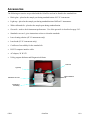
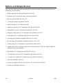
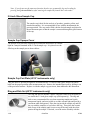
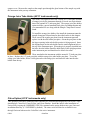
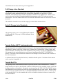
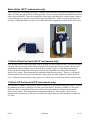
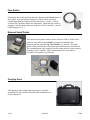
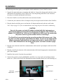
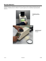
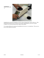
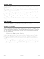
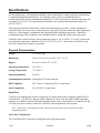
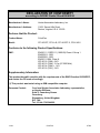
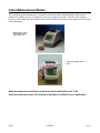
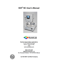
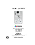
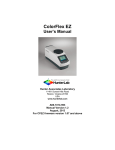
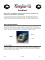
ColorFlex Notice: Use of this equipment in a manner not specified by the manufacturer may impair the protection afforded by the equipment. The ColorFlex system consists of a ColorFlex optical sensor and an IBM-compatible computer composed of the system unit, monitor, keyboard, and mouse. The computer may have been userprovided or purchased with the sensor and software. A printer may also be used with the system. The ColorFlex Sensor The ColorFlex spectrocolorimeter is a versatile, compact color measurement instrument that can be used on products of virtually any size and in industries as diverse as paint and textiles. It is available in two different models, 45°/0° and diffuse/8° (sphere). The label on the bottom of the instrument identifies the geometry. The instrument is designed for use with the sample port facing up or forward. Sample port LCD screen (display) Keypad The Read Button The Read (lightning bolt) button on the keypad, also known as the “Sensor button,” can be used to perform any command or macro assigned to it through the Toolbar command on the Configure menu. By default, this button activates a sample measurement. To assign it another function, see the Toolbar section in the Configure chapter, Chapter 9. 07/02 ColorFlex 13-1 The diffuse model 13-2 ColorFlex 07/02 Accessories The following accessories are provided with the ColorFlex and can be found in the standards box. • Black glass - placed at the sample port during standardization of 45°/0° instruments. • Light trap - placed at the sample port during standardization of diffuse/8° instruments. • White calibrated tile - placed at the sample port during standardization. • Green tile - used to check instrument performance. Use of the green tile is described on page 24-3. • Standards care card - gives instructions on how to clean the standards. • Lens cleaning solution (45°/0° instruments only). • Lens brush (45°/0° instruments only). • Certificate of traceability for the standard tile. • RS-232 computer interface cable. • AC adapter, 20 W/15V. • Utility program diskettes and Diagnostics diskette. Green tile Light trap White calibrated tile Standards care card Certificate of traceability 07/02 ColorFlex 13-3 Options and Sample Devices Any or all of the following options and sample devices may be included. HunterLab part numbers are included for your convenience. • Sample clamp/port-forward stand (HL#D02-1010-459), • Port inserts [45°/0° instruments only] (various part numbers), • Bar code reader kit (HL#D02-1010-715), • 2.5-inch glass sample cup (HL#04-7209-00), • Sample cup opaque cover (HL#04-4000-00), • Sample cup port plate [45°/0° instruments only] (HL#04-6622-00), • Ring and disk set [45°/0° instruments only] (HL#02-4579-00), • Orange juice tube holder [45°/0° instruments only] (HL#D02-1011-127), • Citrus option [45°/0° instruments only] (HL#UNI-Citrus/CFLX), • OJ4 orange juice standard, uncalibrated (HL#A11-1011-509), • Set of 6 orange juice standards, uncalibrated (HL#A11-1011-510), • Tomato option [45°/0° instruments only] (HL#UNI-Tomato/CFLX), • Tomato red tile [45°/0° instruments only] (HL#11-0202-00 for tile, TILE-CAL-TRACEABLE for calibration to traceable standards), • Skein holder [45°/0° instruments only] (HL#02-7396-00), • 1.25-inch glass port insert [45°/0° instruments only] (HL#02-6624-05), • 1.25-inch UV port insert [45°/0° instruments only] (HL#D02-1010-618), • Foot switch (HL#D02-1010-327), • External serial printer (HL#L01-1010-678 for 110V, L01-1010-679 for 220V), • Carrying case (HL#D02-1010-619). 13-4 ColorFlex 07/02 Sample Clamp/Port-Forward Stand The port-forward stand holds the instrument securely in the port-forward position and the sample clamp allows samples to be held flat at the sample port when the instrument is in this orientation. To attach the stand to the ColorFlex, lay the instrument on its side and install the two screws through the stand into the bottom of the instrument using the Allen wrench provided. To use the sample clamp, pull the spring-loaded clamp away from the sample port, insert the sample, and gently release the clamp. Port Inserts (45°/0° instruments only) Port inserts with various-sized openings may be purchased and placed at the reflectance port to allow for a smaller area of view than the standard size. Remove the standard port insert by pulling it out of the port insert retainer. Replace it with the special port insert. Make sure that the flat portion of the insert is facing outward with the beveled portion toward the interior of the sensor. Then standardize the instrument. Any change in port size must be followed by standardization on both the black glass and the white tile. 07/02 ColorFlex 13-5 Bar Code Reader Kit The bar code reader attaches to the communications port of the ColorFlex and allows input of a 24-character bar code ID. An AC adapter is also provided. Installing the Bar Code Reader The ColorFlex is capable of reading and storing sample IDs from a bar code reader. The bar code reader, cable, and AC power supply may be purchased as optional equipment from HunterLab. To assemble the bar code reader, follow the instructions below. 1. Plug the male 9-pin connector of the scanner wand into the female 9-pin connector of the short RS232 adapter cord. Screw the pieces together firmly. 2. Plug the opposite end of the RS-232 adapter into the right (DB-9) port on the back of the ColorFlex. 3. Power for the bar code reader is obtained from the AC power supply. Plug the round connector of the scanner wand into the AC power supply connector. 4. Plug the AC power cord into an electrical outlet. 5. Attach the wand holder to the ColorFlex at a convenient location. Bar Code Reader Programming Your bar code reader will come pre-programmed by HunterLab. However, if unforeseen circumstances require that you re-program it, follow the instructions below. The bar code reader must have three firmware features modified from the factory default in order to work with the ColorFlex sensor. These changes are made by reading the available bar codes in the Programming Menu. Use the following sequence to set the features for use with the ColorFlex sensor. All three features to be changed are located on the “Input/Output Parameters & Format” pages (pp. 4 and 5) of the Programming Menu. This command sequence uses the ENTER and EXIT codes found on the Input/Output pages and the scan codes found on the inside of the back cover. Unfold the back cover so that you can access all three pages at once. 13-6 ColorFlex 07/02 To operate the bar code scanner, hold the wand at a slight angle (10 to 30 degrees) from vertical. Place the wand on the page either to the right or left of the code to be scanned and move the wand at a steady speed across the code to the other side. Do not stop until the bar code is completely passed over. The red light at the tip of the bar code reader will blink twice when scanning the ENTER code and will blink once for all other codes when the codes have been scanned correctly. You must look for the blink for each code scanned. If the reader does not blink, try again. If you miss seeing the blink, or are unsure if it blinked or not, scan the EXIT code and start the sequence again. To modify the scanner setup, complete the following steps: 1. Change the default parity to “SPACE.” Perform the following scan sequence: ENTER, ROMAN NUMERAL II, B, EXIT. 2. Change the default preamble. Perform the following scan sequence: ENTER, ROMAN NUMERAL III, C, 0, 1, C, 4, 0, C, 6, 5, C, 5, B, EXIT. 3. Change the default postamble. Perform the following scan sequence: ENTER, ROMAN NUMERAL IV, A, EXIT. Note: The information contained in this section is specific for use with the ColorFlex sensor. For additional information regarding features, maintenance, or use of the bar code reader, please see the manuals provided with the bar code reader. Note: The bar code reader is not configured for direct operation with the available software support packages provided by HunterLab. This software package cannot access the bar code information. Reading and Saving Bar Code IDs 1. Switch the ColorFlex to Setup mode and go to the Instrument Setup screen. 2. Turn Autosave ON. 3. Switch the ColorFlex to Read mode. 4. Select the appropriate setup. You are prompted to read the sample or ID from the bar code reader. Note: If WORKING is the selected standard type, you will first be prompted to read the standard or ID. 5. Position the ColorFlex on the specimen and take a measurement using the Read key. The ColorFlex again asks for sample or ID. 6. Enter the sample ID by swiping the bar code reader wand across the bar code. The instrument beeps after the ID is entered. Note: The sample measurement must be made BEFORE the bar code ID is entered. When the datalog is printed to a serial printer, the bar code ID appears with each reading. 07/02 ColorFlex 13-7 Note: If you do not use the autostore function, then be sure to manually log each reading by pressing the Up Arrow/Print key after entering the sample ID from the bar code reader. 2.5-inch Glass Sample Cup The sample cup is ideal for the analysis of powders, granules, pellets, and translucent samples. It is recommended for use with the instrument in the port-up position. The cup can be filled with the desired sample and placed at the measurement port so that the sample is measured through the glass bottom of the cup. Sample Cup Opaque Cover The opaque cover provides a light trap to exclude the interference of external light on a sample contained in the 2.5-inch sample cup. It is placed over the filled cup at the sample port as shown below. Sample Cup Port Plate (45°/0° instruments only) This port insert is specially designed to accommodate the 2.5-inch (64-mm) glass sample cup and to hold it in the proper position at the measurement port. Remove the standard port insert by pulling it out of the port insert retainer. Replace it with the sample cup port insert, then standardize the instrument. Ring and Disk Set (45°/0° instruments only) The ring and disk set includes a plastic ring and ceramic disk designed for use inside the 2.5-inch glass sample cup (sold separately). The ring and disk set are recommended for use when measuring translucent liquids, transparent liquids, and semi-solids to exclude external light and provide a consistent white background. Place the ring inside the sample cup and fill the cup with the sample to a level above the ring. Then place the ceramic disk on top of the sample (until it rests on top of the ring) with the white portion facing the sample. If desired, cover the entire assembly with the 13-8 ColorFlex 07/02 opaque cover. Measure the sample at the sample port through the glass bottom of the sample cup with the instrument in the port-up orientation. Orange Juice Tube Holder (45°/0° instruments only) This holder is designed to allow the viewing of a 1-inch glass test tube of orange juice by the instrument through a viewed area equivalent to that of the optional 0.75-inch port plate. The orange juice tube holder option includes a special mounted black glass for standardization and is recommended for use along with the Sample Clamp/Port-Forward Stand. To install the orange juice holder, first install the instrument onto the sample clamp/port-forward stand as described earlier in this chapter. Then, remove the regular port plate from the instrument port and replace it with the tube holder port plate. Orient the port plate so that the larger opening in the tube holder portion is facing upward. Insert the alignment pin on the tube holder into the small alignment hole at the top of the instrument port. When the pin is properly installed into the hole, the tube holder should be held firmly in the upright position at the instrument port and should not be allowed to rotate. Then, standardize the instrument with the normal 0.75-inch port plate in place. Replace the 0.75-inch port plate with the orange juice tube holder port plate. To use the orange juice tube holder, fill the 1-inch glass tube with orange juice and insert the tube into the tube holder from the top. Citrus Option (45°/0° instruments only) This option provides three additional indices that may be calculated and displayed in Universal’s color data displays, Citrus Red, Citrus Yellow, and Citrus Number. Install the indices after installation of Universal by copying the CMRINDEX.CDX file contained on the option diskette into your Universal installation directory (C:\UNIVERSE by default). The citrus scales will then be available for use through Universal whenever the ColorFlex is the active instrument. 07/02 ColorFlex 13-9 Calculations for the citrus scales are given in Appendix A. OJ4 Orange Juice Standard This option provides an uncalibrated plastic OJ4 standard for creating a new instrument hitch or checking the current instrument hitch to the United States Department of Agriculture’s (USDA) standards. This standard is also available with USDA calibration for an additional fee. When a citrus scale is to be used, read the OJ4 standard and hitch the instrument to the XYZ values given on the standard label. Save the standard and recall it to rehitch the instrument whenever citrus scales are to be measured. The standard is intended for use with the orange juice tube holder described above. Set of 6 Orange Juice Standards This option provides a set of six uncalibrated OJ standards (OJ1 through OJ6). They may be USDA calibrated for an additional fee. Tomato Option (45°/0° instruments only) This option provides seven additional indices that may be calculated and displayed in Universal’s color data displays: Tomato Color Score, Tomato Juice, Tomato Paste, Tomato Sauce, Tomato Catsup, and Tomato A/B Ratio. Install the indices after installation of Universal by copying the CMRINDEX.CDX file contained on the option diskette into your Universal installation directory (C:\UNIVERSE by default). The tomato scales will then be available for use through Universal whenever the ColorFlex is the active instrument. A calibrated tomato tile (as described below) is included with this option. Calculations for the tomato scales are given in Appendix A. Tomato Red Tile This option provides an uncalibrated tomato red porcelain enamel on steel instrument tile. You may assign tomato score values to the tile based on known USDA tomato color standards in order to hitch the instrument to those soft standards. Alternately, you may purchase the TILE-CAL-TRACEABLE option from HunterLab to have tomato score and color values assigned to the tile at the factory. When a tomato score is to be used, read the tomato tile as a standard and hitch the instrument to the L, a, b values given on the standard label. Save the standard and recall it to rehitch the instrument whenever tomato scores are to be measured. 13-10 ColorFlex 07/02 Skein Holder (45°/0° instruments only) This is a device for measuring yarn skeins. Wind the yarn around the skein holder in multiple taut layers until it is effectively opaque and is as flat as possible. Secure it in place with the detachable arms on the sides of the skein holder. Place the skein holder at the sample port and back it with the sample clamp or a white backing tile to provide a consistent background and pressure. Make several measurements of the skein, rotating the holder 90° between measurements and averaging the readings for the final result. 1.25-inch Glass Port Insert (45°/0° instruments only) This option provides a snap-in port plate with an opening one inch in diameter that is covered with glass. The glass insert protects the inside of the instrument from sample and airborne particles. Remove the standard port insert by pulling it out of the port insert retainer. Replace it with the glass port insert. Make sure that the flat portion of the insert is facing outward with the beveled portion toward the interior of the sensor. Then standardize the instrument with the glass in place. However, you should check measurements of the green and white tiles and perform any other diagnostics without the glass cover. Difference measurements using a glass cover will be more accurate than absolute measurements. 1.25-inch UV Port Insert (45°/0° instruments only) This port insert contains a 420-nm filter to prevent light below 420 nm from hitting the sample. Remove the standard port insert by pulling it out of the port insert retainer. Replace it with the UV port insert. Make sure that the flat portion of the insert is facing outward with the beveled portion toward the interior of the sensor. Then standardize the instrument with the UV filter in place. However, you should check measurements of the green and white tiles and perform any other diagnostics without the UV filter. 07/02 ColorFlex 13-11 Foot Switch Pressing the foot switch performs the same function as the Read button on the keypad. A pre-programmed sequence of steps can be carried out without input from the computer keyboard or mouse. See the “Toolbar” section of the Configure chapter for instructions. Install the foot switch by plugging it into the round connector on the back of the ColorFlex. (See the picture on page 13-13.) External Serial Printer The external serial printer connects to the serial port of the ColorFlex and prints the setup data when the Read key is pressed and held or the measurement data when the Up Arrow/Print key is pressed. The serial printer sold by HunterLab is a dot matrix printer that operates at 9600 baud. The communications cable supplied with the printer must be used to connect the printer to the ColorFlex. More information on the serial printer is provided in its separate User's Manual. Carrying Case This option provides a hard-sided carrying case designed specifically for the ColorFlex that allows the instrument to be easily transported. 13-12 ColorFlex 07/02 Installation The following instructions guide you through the initial installation of your ColorFlex system. 1. Unpack all cartons and remove wrappings and cable ties. Inspect for damage and notify the carrier and HunterLab immediately if any is discovered. Save the packing materials in case it becomes necessary to return the instrument to the factory. 2. Place the ColorFlex on a flat, stable surface near an electrical outlet. 3. Connect the jack connector of the AC adapter to the jack acceptor on the left back of the ColorFlex. 4. Plug the female end of the power cord into the AC adapter and the male end into a wall outlet. Note: Refer to page 13-18 for recommendations concerning the power line and its conditioning. CAUTION Use only the power cord and AC adapter included with this instrument or a replacement obtained from HunterLab (HunterLab Part Number C04-1005-631 for adapter, A13-1002-655 for 110V cord, A13-1002-656 for 220V cord). Be certain that the power cord is in good condition before connecting it. The ColorFlex is grounded using the grounding portion of this power cord. Only plug this cord into a properly grounded power outlet. Do not use an inappropriate adapter to plug the instrument into an ungrounded outlet or electric shock may occur. More information on the wiring of the power cord can be found on page 13-19. 5. Plug the 9-pin connector end of the communications cable into the 9-pin adapter on the back of the ColorFlex. 6. Plug the second 9-pin connector of the communications cable into the appropriate communications port of the computer. 7. Install the foot switch, if one has been purchased. 8. Turn on the system by pressing the Read key and allow it to warm up for at least thirty minutes before use. (If the screen clears, the instrument has entered standby mode, but is still warming up.) Connector for foot switch 9-pin serial port Jack for AC adapter cable 07/02 ColorFlex 13-13 Standardization Standardization on a ColorFlex model with 45°/0° geometry requires reading of the black glass and white tile. Standardization on a diffuse/8° ColorFlex requires you to read both the light trap and the white tile. Standardizing a diffuse ColorFlex using the light trap Standardizing a 45°/0° ColorFlex using the black glass 13-14 ColorFlex 07/02 Standardizing the ColorFlex using the white tile Standardization can be done through the software or directly through the ColorFlex firmware. More detailed information about your ColorFlex sensor and its standardization is given in its separate ColorFlex User's Guide and in the Sensor chapter of this manual. It is recommended that the instrument be standardized at least once every eight hours. Then you may proceed with sample measurement. 07/02 ColorFlex 13-15 Maintenance This section outlines the parts of the sensor you must maintain in order for the instrument to function properly. More detailed information about your ColorFlex sensor is given in its separate User's Guide. Notice: Do not disassemble the instrument and attempt to clean the optical components. Do not open the instrument or remove any covers except using the instructions given in this User’s Manual or under the direction of HunterLab Customer Support. Replacing the Lamp Lamp replacement requires a trained technician. Contact HunterLab Customer Support to arrange for lamp replacement. Please read “When You Need Assistance,” page 25-6, prior to telephoning HunterLab. Maintaining the White Tile, Green Tile, Black Glass, and Light Trap When you're not using the instrument green tile and black glass, keep them in the standards box. Keep the white tile over the sample port to protect the interior of the instrument. Inspect each tile for dust and fingerprints before standardizing ColorFlex. The tiles can be cleaned using a soft nylon bristle brush and a solution of warm water with a laboratory grade detergent such as SPARKLEEN. Rinse the tiles in a stream of warm tap water. Blot the tiles dry using a clean, non-optically brightened, lint-free paper towel. Allow the tiles to stabilize to room temperature before use. Note: SPARKLEEN is manufactured by Fisher Scientific Co., Pittsburgh, PA 15219 and may be ordered from them using catalog number 4-320. One tablespoon of SPARKLEEN should be added to every gallon of water. Also, keep the light trap in the standards box when not in use to prevent it from becoming scratched or collecting dust. Before standardizing ColorFlex, check the light trap for scratches and dust. Significant scratches may cause standardization to be in error. If the light trap is scratched, call HunterLab to order a replacement. Note: The light trap is used only with instruments having the diffuse/8° geometry. Cleaning the ColorFlex The ColorFlex is NOT waterproof, but you may wipe the exterior of the case with a damp cloth. For 45°/0° instruments only, also remove the port plate and clean the glass underneath with the included lens brush and lens cleaner or with a small amount of soapy water on a lint-free cloth or towel. Operating Conditions ColorFlex can be stored in an area with a temperature range of -10°F to 140°F (-23°C to 60°C) and can be operated under temperature conditions of 50°F to 110°F (10°C to 43°C). The ColorFlex may be operated in humidity conditions from 5% to 85%. Do not leave ColorFlex in an area where temperature or humidity extremes are possible. 13-16 ColorFlex 07/02 Archiving Setups All ninety-nine setups can be stored in non-volatile memory by choosing “Archive Setups” from the ColorFlex menu. When this procedure is performed, all setups will then be stored in non-volatile memory and will be safeguarded from loss due to memory failure. It is recommended that you store your setups in non-volatile memory on a regular basis. This will protect your setups should you experience an unforeseen memory loss. If you create additional setups or change existing setups and wish to protect them you must perform the archiving procedure again. Prior to sending the ColorFlex to HunterLab for service, be sure to store your setups in non-volatile memory. Error Messages ColorFlex may display an error message to alert you that the instrument needs service. Refer to your ColorFlex User's Guide for an explanation of the various possible error messages. Resetting the ColorFlex On rare occasions, your ColorFlex may display unusual characters or otherwise act strangely. This is sometimes caused by power fluctuations. These problems can generally be corrected by resetting the unit. This is done by choosing “Reset Setups” from the ColorFlex menu, if possible, or by pressing three keys simultaneously: Left Arrow key + Right Arrow key + Read key. Hold these keys until the ColorFlex beeps, and then the RAM will be cleared and reset. If at all possible, use the “Reset Setups” menu command to reset the unit. The three key press method of resetting the unit should be reserved for those instances where the display is so scrambled as to be unusable. Note: Resetting the RAM results in loss of all entered setups and product standards and returns setup parameters to their default values. If possible, you may want to archive your setups or print out your setup data prior to resetting the ColorFlex. This will facilitate recall or re-entry. 07/02 ColorFlex 13-17 Specifications For best performance, your instrument should be placed where there is ample work space with medium or subdued illumination and no drafts. For optimum results, a clean, air-conditioned area is recommended with a relative noncondensing humidity of 5-85% and relatively constant temperature not exceeding 110°F (43°C). For specification performance, the recommended temperature range is 7082°F (21°-28°C). The instrument should be connected to a stable, instrument-grade power line. If other equipment is connected to the same power line, a transient power surge may be produced when the other equipment is turned on. If this happens, restandardize the instrument before making measurements. HunterLab recommends using a line conditioner with a minimum 600VA rating and a battery back-up system. ColorFlex can be stored in an area with a temperature range of -10° to 140°F (-23° to 60°C) and can be operated under temperature conditions of 50° to 110°F (10° to 43°C). Do not leave ColorFlex in any area where temperature extremes are possible. Physical Characteristics Weight 11.25 lb (4.5 kg) Dimensions 36 cm x 13 cm x 16 cm (14.4” x 5.2” x 6.4”) Display 6.4 cm x 6.4 cm (2.56” x 2.56”) Operating Temperature 10° to 43° C Storage Temperature -23° to 60° C Operating Humidity 5 to 85% Communications Interface Locking RS-232 serial connector RFI Compliance FCC Class A (Commercial), IEC, or equivalent. Safety Compliance UL, CSA, IEC, or equivalent. Serial Port ColorFlex can communicate with any computer or 80-column printer that is equipped with an RS-232 serial interface. The RS-232 cable provided by HunterLab can be used only with an IBM-compatible computer or an IBM- or Hewlett Packard-compatible printer with a serial interface. In addition, the RS232 cable may also be used to connect the ColorFlex with an optional bar code scanner. Note: Color plots, color difference plots, and spectral plots may only be printed on an HPcompatible printer. Serial Port Configuration The ColorFlex RS-232 serial port is configured in the following manner: 13-18 ColorFlex 07/02 Baud rate from 300 to 57600 No parity 8 data bits 1 stop bit. Your output device must be configured in the same way in order to communicate with ColorFlex. Note that Universal Software’s maximum baud rate is 19200. Note: Several baud rates are available with ColorFlex. Be sure to change the INSTRUMENT SETUP of ColorFlex to agree with the baud rate selected for your output device. Handshake Output from the ColorFlex serial port is controlled by XON/XOFF handshaking. Data output is stopped when the output device sends an XOFF character to ColorFlex. Data flow begins again when ColorFlex receives an XON character. Conditions of Illumination and Viewing Source Dual-beam xenon flash lamp, >500,000 flashes Source UV Content Nominal match to D65 Integrating Sphere 63.5 mm diameter, high-efficiency white coating Port Diameters/View Diameters 45/0 Model 31.8 mm (1.25”)/25.4 mm (1.0”) Diffuse/8° 14.3 mm (0.56”)/8.0 mm (0.31”) Power Required External 120/220 V locking AC adapter Power Cord Wire Color Code: Color Definition 220V Cord Brown LINE Blue NEUTRAL Green/Yellow SAFETY 110V Cord Black White Green LINE NEUTRAL SAFETY Instrument-Computer Ground Potential Check: Perform this check if the power cord wiring is being changed, such as for replacement of the cord or if changing the plug. 07/02 ColorFlex 13-19 The instrument serial port ground connection is referenced to the instrument's internal frame and safety ground. Before connecting the communication cable to the instrument serial port, apply power to the instrument and the host computer. Check the ground potential (voltage) between the serial port ground pins on the computer and the instrument. The ground connection is pin 5 on DB-9 connectors and pin 7 on DB-25 connectors. Voltages in excess of 5VAC at 110V input power, or in excess of 10VAC at 220V input power may indicate a difference in ground wiring and can damage the instrument and/or the computer. Check the wiring and take other steps as needed to reduce this difference before connecting the communications cable. You may also use a data optoisolator. Instrument Performance Spectral Data Range (nm) 400 - 700 Photometric Range 0 - 150% Spectral Resolution 10 nm Spectral Bandpass < 12 nm Measurement Speed (at 23° C) Warm-up time Command-to-data output Read-to-read ≤ 1 second ≤ 1 second ≤ 3 seconds Warm-up Period 30 minutes prior to testing Sample Storage Capacity 500 spectral samples 999 tristimulus samples 99 standards 99 setups You may test the repeatability of your instrument as follows: 1. Turn the ColorFlex on and allow it to warm it up for 30 minutes. Meanwhile, clean the black glass (45°/0° instruments) and white tile as described in Chapter 24 and allow the tiles to return to room temperature. 2. Standardize the instrument. 3. Configure your color data display to show DE* using D65/10°. 4. Center the instrument’s white standard tile at the measurement port. Do not move or remove the tile for the remainder of the test. 5. Read the white tile as a standard. 6. Configure the timed read feature to automatically make and average 20 more measurements with a read interval of 7 seconds and then initiate reading of the tile as a sample. 13-20 ColorFlex 07/02 7. When all readings are complete, examine the average DE* value. The instrument passes the repeatability test as long as the average DE* value is less than or equal to 0.04. Contact HunterLab Customer Support as described on page 25-6 if the instrument fails the repeatability test. Note: Performance specifications are subject to change without notice. Regulatory Notice A copy of the Declaration of Conformity according to ISO/IEC Guide 22 and EN 45014 follows on the next page. 07/02 ColorFlex 13-21 DECLARATION OF CONFORMITY according to ISO/IEC Guide 22 and EN 45014 Manufacturer's Name: Hunter Associates Laboratory, Inc. Manufacturer's Address: 11491 Sunset Hills Road Reston, Virginia U.S.A. 20190 Declares that the Product: Product Name: ColorFlex Model: CFLX-DIFF, CFLX-45, CFLX-DIFF-2, CFLX-45-2 Conforms to the following Product Specifications: EMC: EN55011 / CISPR 11 (1990-09) Class A Group 1 EN50081-1:1992 EN50082-1:1992 EN55011:1994, Class A IEC 801-2 (1984), 8 KV IEC 801-3 (1984), 3 V/m (27-500 MHz) IEC 801-4 (1984) + 1 KV IEC 801-5 (1991), 2 KV Supplementary Information: This product herewith complies with the requirements of the EMC Directive 89/336/EEC, and carries the CE mark accordingly. (1) This product was tested using an IBM compatible computer. European Contact: 13-22 Your local Hunter Associates Laboratory representative, or Hayden Williams, Suite 6, Canonbury House Canonbury Shrewsbury, United Kingdom SY3 7AH Tel: 011-44-1743-344090 ColorFlex 07/02 Color Measurement Notes The ColorFlex spectrocolorimeter is a versatile color measurement instrument that can be used on products of virtually any size, in industries as diverse as paint and textiles. Because of its compact design, it can be used to measure objects that would be difficult to position at the sample port of a larger color instrument. Measuring the color of semi-solids using the glass sample cup Measuring multiple layers of fabric Sample measurement methods can be found on the world wide web! Visit www.hunterlab.com to see if an illustrated method is available for your application. 07/02 ColorFlex 13-23 13-24 ColorFlex 07/02