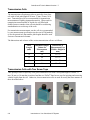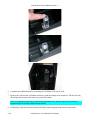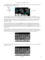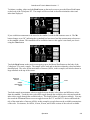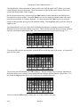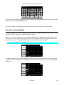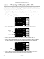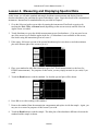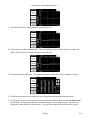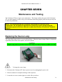
1
ColorQuest XT ® User’s Manual A60-1011-346 Manual Version 1.7 Hunter Associates Laboratory 11491 Sunset Hills Road Reston, Virginia 20190, USA www.hunterlab.com An ISO 9001:2008 Certified Company Copyrights and Trademarks This documentation contains proprietary information of Hunter Associates Laboratory, Inc. Its reproduction, in whole or in part, without the express written consent of Hunter Associates Laboratory, Inc. is prohibited. Windows is a registered trademark of Microsoft Corporation. Spectraflect is a trademark of Labsphere, Inc. Teflon is a registered trademark of E.I du Pont de Nemours and Company. Please keep this manual in a safe place. HunterLab must charge a fee for replacement manuals. Safety Notes For your safety when using the ColorQuest XT, you should pay particular attention to the following types of statements in this User’s Manual. Each description is shown in its representative typeface. Notice: General safety instruction that should be observed at all times while operating the instrument. CAUTION Specific safety instruction critical to the type of instrument operation being explained in the area of the manual where the caution appears. Note: Additional clarification of instructions, not safety-related. The following symbol indicates that there may be a danger of electric shock from high voltage if the given instructions are not followed carefully. Table of Contents HOW THE USER’S MANUAL IS ORGANIZED ..................................................... 1-1 INTRODUCTION TO YOUR COLORQUEST XT SYSTEM................................. 2-1 ColorQuest XT Features .................................................................................................................... 2-2 Touch Screen ..................................................................................................................................... 2-2 Transmission Compartment .............................................................................................................. 2-2 Macro/Read Button ........................................................................................................................... 2-2 Power On Light ................................................................................................................................. 2-2 Accessories ........................................................................................................................................... 2-3 Options and Sample Devices .............................................................................................................. 2-4 Foot Switch Assembly ...................................................................................................................... 2-5 External Serial Printer ....................................................................................................................... 2-5 Transmission Clamp.......................................................................................................................... 2-5 Transmission Cell Holder ................................................................................................................. 2-7 Transmission Cells ............................................................................................................................ 2-8 Transmission Cells with Two Screw Tops ........................................................................................ 2-8 Transmission Spill Tray .................................................................................................................... 2-9 Flow-Through Transmission Cell Holder and Cells ....................................................................... 2-10 Holder for Small Volume Transmission Cells and 10-mm Small Volume Transmission Cells ..... 2-11 Cylindrical Cell Holder ................................................................................................................... 2-12 Semi-micro Cell Holder and Optical Assembly.............................................................................. 2-13 Transmission Preform Holder ......................................................................................................... 2-17 Applets ............................................................................................................................................ 2-18 EasyMatch QC Software ................................................................................................................. 2-18 INSTALLATION ........................................................................................................... 3-1 Installation of the ColorQuest XT System ....................................................................................... 3-1 OPERATION.................................................................................................................. 4-1 Loading Applets .................................................................................................................................. 4-1 Standardizing ...................................................................................................................................... 4-3 General .............................................................................................................................................. 4-3 Standardization Modes ...................................................................................................................... 4-4 Instructions ........................................................................................................................................ 4-4 Taking Readings ................................................................................................................................. 4-6 Using the Color Applet ..................................................................................................................... 4-6 Using the Index Applets .................................................................................................................... 4-8 Using the Spectral Applets .............................................................................................................. 4-11 LESSONS ........................................................................................................................ 5-1 Lesson 1. Lesson 2. Lesson 3. Lesson 4: Loading an Applet ............................................................................................................ 5-1 Measuring and Displaying Color Data ........................................................................... 5-3 Measuring and Displaying Index Data ........................................................................... 5-6 Measuring and Displaying Spectral Data..................................................................... 5-10 COLOR MEASUREMENT NOTES ........................................................................... 6-1 i Selecting, Preparing, and Presenting Samples ................................................................................. 6-1 More on Sample Presentation to the Instrument ............................................................................... 6-1 Transmittance Measurements............................................................................................................ 6-2 MAINTENANCE AND TESTING............................................................................... 7-1 Replacing the Source Lamp ............................................................................................................... 7-1 Replacing the Fuses ............................................................................................................................ 7-5 Cleaning the Touch Screen ................................................................................................................ 7-7 Cleaning the Lens Surface and Didymium Filter ............................................................................ 7-9 Cleaning the Sphere.......................................................................................................................... 7-10 Performing Diagnostics .................................................................................................................... 7-11 Energy ............................................................................................................................................. 7-11 Repeatability ................................................................................................................................... 7-12 Wavelength ..................................................................................................................................... 7-13 Clock ............................................................................................................................................... 7-15 Password ......................................................................................................................................... 7-15 Setup ................................................................................................................................................ 7-16 Check Calibration of Touch Screen ................................................................................................ 7-18 Calibrate Touch Screen ................................................................................................................... 7-18 SPECIFICATIONS ........................................................................................................ 8-1 Physical Characteristics ..................................................................................................................... 8-1 Environmental Requirements ............................................................................................................ 8-1 Power and Grounding ........................................................................................................................ 8-2 Conditions of Illumination and Viewing .......................................................................................... 8-3 Instrument Performance .................................................................................................................... 8-4 Regulatory Notice ............................................................................................................................... 8-5 INSTRUMENT REPLACEMENT, REPAIR, PROBLEMS, AND QUESTIONS . 9-1 Warranty ............................................................................................................................................. 9-1 Shipping Claims .................................................................................................................................. 9-2 Breakage or Damage ......................................................................................................................... 9-2 Shortage............................................................................................................................................. 9-2 Incorrect shipment ............................................................................................................................. 9-3 Returns ................................................................................................................................................ 9-4 When You Need Assistance ............................................................................................................... 9-5 MEASUREMENT VALUES ...................................................................................... 10-1 Color Scales and Related Color Difference Scales ........................................................................ 10-1 CIE Tristimulus XYZ Scale ............................................................................................................ 10-1 CIE Chromaticity Coordinates, Yxy ............................................................................................... 10-1 Opponent-Color Scales (Hunter Lab, CIE 1976 L*a*b*, and CIEL*C*h) .................................... 10-2 Indices ................................................................................................................................................ 10-6 Absorbance ...................................................................................................................................... 10-6 ADMI-10 mm and 50 mm............................................................................................................... 10-6 APHA-10, -20, and -50 mm ............................................................................................................ 10-6 ASBC-10 mm .................................................................................................................................. 10-7 ASTM Color.................................................................................................................................... 10-7 CMC ................................................................................................................................................ 10-9 ii EBC-10 mm .................................................................................................................................. 10-10 Gardner D6166-10 mm ................................................................................................................. 10-10 Saybolt........................................................................................................................................... 10-11 Yellowness Index .......................................................................................................................... 10-13 APPLET PROGRAMMING ........................................................................................A-1 Installing the Applet Manager.......................................................................................................... A-1 Using the Applet Manager ................................................................................................................ A-5 GLOSSARY .................................................................................................................... B-1 REFERENCES ...............................................................................................................C-1 iii ColorQuest XT User’s Manual Version 1.7 CHAPTER ONE How the User’s Manual is Organized Welcome to the ColorQuest XT User’s Manual! Take some time now to read through the manual before you begin using the instrument. The User’s Manual is divided into the following chapters: • Introduction to Your ColorQuest XT System • Installation • Operation • Lessons • Color Measurement Notes • Maintenance and Testing • Specifications • Instrument Replacement, Repair, Problems, and Questions • Measurement Values The “Introduction” chapter describes the instrument, its features, and the accessories and options that may accompany the instrument. The “Installation” chapter provides specific instructions on setting up the instrument. The “Operation” chapter describes how to standardize the instrument, load the desired applet, and then take readings. The “Lessons” chapter provides four examples of instrument operation that can be used for practice. The “Color Measurement Notes” chapter gives guidelines on measuring different types of samples using the ColorQuest XT. The “Maintenance and Testing” chapter explains the maintenance that needs to be performed on the instrument and its standards and describes the available diagnostics. The “Specifications” chapter provides the various instrumental specifications. How the User’s Manual is Organized 1-1 ColorQuest XT User’s Manual Version 1.7 “Instrument Replacement, Repair, Problems, and Questions” outlines your instrument warranty and how to get technical support and/or service for your instrument. “Measurement Values” explains the various color scales and indices that are available with this instrument. The three appendices explain how you can program your own applets and use the applet manager software, and provide a glossary and bibliographical references. 1-2 How the User’s Manual is Organized ColorQuest XT User’s Manual Version 1.7 CHAPTER TWO Introduction to Your ColorQuest XT System Notice: Use of this equipment in a manner not specified by the manufacturer may impair the protection afforded by the equipment. The ColorQuest XT is a dual beam xenon flash spectrophotometer with a wavelength range from 400 to 700 nanometers (nm). All tristimulus integrations are based on a triangular bandpass of ten nm and a wavelength interval of ten nm. The instrument can measure regular and total transmitted color of a product. The sensor uses a plastic integrating sphere that is six inches (152.4 mm) in diameter and coated with Spectraflect™, which diffuses the light from the lamp. The light illuminates the sample and is transmitted through it. A lens is located at an angle of 8° from the perpendicular to the sample surface. The lens collects the transmitted light and directs it to a diffraction grating which separates the light into its component wavelengths. These components are then measured by a diode array and converted into usable data. Touch screen Transmission compartment Macro/Read button Power On light Sphere cover that is removable for cleaning the interior of the sphere Lens port Transmission (sphere) port The ColorQuest XT The ColorQuest XT may be operated through the touch screen display on the instrument itself (as described in this manual), and it may also be operated while connected to a computer running EasyMatch QC Software. Refer to the EasyMatch QC User’s Manual and help file for more information on operating the ColorQuest XT from a computer. Introduction to Your ColorQuest XT System 2-1 ColorQuest XT User’s Manual Version 1.7 ColorQuest XT Features The ColorQuest XT possesses the following default features: Touch Screen The touch screen assembly allows commands to be given to the sensor and then displays the data received back from the sensor, such as the color scale values for a read sample. The backlit liquid crystal display (LCD) shows 240 x 128 pixels. The screen may be swiveled and tilted to the most convenient position for operation and viewing. In order to give commands to the instrument and respond to prompts, you will need to literally touch designated areas of the screen. A highlighted, labeled area of the screen that performs a specific function will be called a “button” or “key” in this manual for instructional purposes, even though there is no physical raised area or moving part actually present. You may touch a button or key using a fingertip or a stylus such as a pencil eraser. You need not press the button hard in order to activate its command. Each proper button touch causes the screen assembly to beep. The touch screen automatically powers down if it is not touched for four consecutive minutes. Touch anywhere on the screen to reactivate it. Transmission Compartment The transmission compartment located in the middle of the sensor is used for measuring the transmitted color of transparent solids or liquids. The transmission compartment door should be closed while standardizing and taking measurements. 1 Macro/Read Button The Macro/Read button initiates a sample measurement and acts as the OK button when the screen shows a standardization prompt. Power On Light The Power On light remains steadily lit while the instrument is plugged in and turned on. 1 Closing the transmission compartment door while making measurements is the best practice for this instrument. For more information, see the note in the Standardizing section of the Operation chapter. 2-2 Introduction to Your ColorQuest XT System ColorQuest XT User’s Manual Version 1.7 Accessories The following accessories are provided with the ColorQuest XT system and can be found in the standards case: • Black card device - placed in the transmission compartment during standardization. • Didymium filter - screwed into the lens as a check for wavelength accuracy. • Fuses - two 3-amp fuses are provided as spares. • Lens brush. • RS-232 communications cable. • Power cord. • Applet manager - software program for loading applets into the touch screen memory. This program is described in detail in Appendix A. • Diagnostics software CD. Introduction to Your ColorQuest XT System 2-3 ColorQuest XT User’s Manual Version 1.7 Options and Sample Devices There are many options and devices available for positioning samples at the measurement port of the ColorQuest XT and for making the instrument easier to use. Any or all of the following options and sample devices may be purchased for use with your ColorQuest XT. HunterLab part numbers are included for your convenience in ordering. • Foot switch assembly (HL#D02-1010-327), • External serial printer (HL#L01-1010-678 for 110V, L01-1010-679 for 220V), • Transmission clamp (HL#C02-1005-444), • Transmission cell holder (HL#C02-1005-481), • Transmission cells (HL#13-8573-20 for 50-mm, B04-1003-801 for 33-mm, 04-4592-00 for 20-mm, 13-8573-40 for 10-mm), • Transmission cells with two screw tops (HL#D12-1011-893 for 10-mm, D12-1011-890 for 20-mm, D12-1011-891 for 33-mm, D12-1011-892 for 50-mm), • Transmission spill tray (HL#D02-1011-568), • Flow-through transmission cell holder and cells (HL#D02-1009-960 for holder, C04-1001-960 for 50-mm cell, C04-1001-959 for 20-mm cell, C04-1001-958 for 10-mm cell), • Holder for small volume transmission cells and 10-mm small volume transmission cells (HL#D021011-886 for holder, A13-1011-613 for cell), • Cylindrical cell holder (HL#D02-1011-550), • Semi-micro cell holder and optical assembly (HL#L02-1012-202), • Transmission preform holder (HL#D02-1011-833), • Applets (various part numbers), • EasyMatch QC Software (HL#EZMQC-CQXT). 2-4 Introduction to Your ColorQuest XT System ColorQuest XT User’s Manual Version 1.7 Foot Switch Assembly The foot switch assembly performs the same actions as the Macro/Read button on the sensor (initiates a sample reading and acts as the “OK” button when the screen shows a standardization prompt). Install the foot switch by plugging it into the round connector on the left end of the ColorQuest XT. External Serial Printer The external serial printer connects to the port labeled “PRN” on the ColorQuest XT’s touch screen and prints the measurement data when the Print area of the touch screen is pressed. The serial printer sold by HunterLab is a dot matrix printer that operates at 9600 baud. The communications cable supplied with the printer must be used to connect the printer to the ColorQuest XT. More information on the serial printer is provided in its separate User’s Manual. Transmission Clamp The optional transmission clamp holds transparent film or sheets in position for regular or total transmission measurements. For measurements in Regular Transmission: 1. Position the transmission clamp so that the curved opening is aligned at the lens port located in the left end of the transmission compartment. The inner curvature of the clamp should align with the outer curvature of the lens. Introduction to Your ColorQuest XT System 2-5 ColorQuest XT User’s Manual Version 1.7 2. When properly aligned, the holes in the bottom of the clamp assembly will align with holes in the floor of the transmission compartment. Place a washer and one 1/4-20 7/8-inch screw in each of the holes and tighten by turning the screw clockwise. (You may finger-tighten the screws or you may use the Allen wrench that is included with the transmission clamp.) 3. Use the touch screen to standardize in regular transmission (RTRAN). 4. Place the film sample at the lens port by pulling forward on the tab at the bottom of the clamp and sliding the transmission clamp holder forward. Place the film at the lens and release the tab. The rubber grommet at the rear of the transmission clamp will firmly hold the sample in place for measurement. 5. Close the transmission compartment door and make the measurement. Transmission clamp as placed in the transmission compartment for measurements in regular transmission. The clamp is placed flat at the lens. For measurements in Total Transmission: 1. Position the transmission clamp so that the curved opening is aligned at the opening of the sphere at the right end of the transmission compartment. The inner curvature of the clamp should align with the outer curvature of the sphere. 2. When properly aligned, the holes in the bottom of the clamp assembly will align with holes in the floor of the transmission compartment. Place a washer and one 1/4-20 7/8-inch screw in each of the holes and tighten by turning the screw clockwise. (You may finger-tighten the screws or you may use the Allen wrench that is included with the transmission clamp.) 3. Use the touch screen to standardize in total transmission (TTRAN). 4. Place the film sample at the sphere opening by pulling back on the tab at the bottom of the clamp and sliding the transmission clamp holder backward. Place the film at the sphere opening and release the tab. The rubber grommet at the front of the transmission clamp will firmly hold the sample in place for measurement. 5. Close the transmission compartment door and make the measurement. 2-6 Introduction to Your ColorQuest XT System ColorQuest XT User’s Manual Version 1.7 Transmission clamp as placed in the transmission compartment for measurements in total transmission. The clamp is placed flat at the sphere. Transmission Cell Holder The optional transmission cell holder permits measurement of liquids in 10-mm, 20-mm, 33-mm, or 50-mm transmission cells. To install it, slide the transmission cell holder into the transmission compartment at the center, widest part of the transmission compartment. Position the holder inside the transmission compartment so that the flat end of the holder is aligned with the left wall of the transmission compartment. The slanted end will be at the sphere wall at the right of the compartment. Ensure that the holder is flush against the sphere wall. Depress and turn the captive screws clockwise. If the holder is slightly off-line, reposition it so that the screws align properly in the holes on the floor of the transmission compartment. You may use the holder for measurements in either total or regular transmission by following the touch screen prompts to standardize in the desired mode. If you are using total transmission (TTRAN), place the cell at the sphere opening at the right of the transmission compartment. If you are using regular transmission (RTRAN), place the cell at the lens port at the left of the transmission compartment. The transmission cell holder holding a 20-mm cell at the sphere opening. Introduction to Your ColorQuest XT System 2-7 ColorQuest XT User’s Manual Version 1.7 Transmission Cells The transmission cell option provides an optically-clear glass cell with a fixed path length of 50 mm, 33 mm, 20 mm, or 10 mm. Transmission cells are recommended for transmission measurements of lightly-pigmented materials. When used for transmission measurements of liquids, the cell filled with distilled water or another clear solvent should be used during standardization to set the top of the scale. For transmission measurements, use the cell size recommended by your measurement specification (such as an ASTM method), or use the general rule that smaller path lengths should be used for more concentrated colorants. The dimensions and volumes of the various transmission cells are as follows: Path Length (mm) Minimum Sample Volume for Measurement (mL) Dimensions of Measurement Face (Width x Height in mm) 10 20 55 x 57 20 40 55 x 57 33 70 55 x 57 50 100 55 x 57 Transmission Cells with Two Screw Tops This option provides an optically-clear glass transmission cell with a fixed path length of 50 mm, 33 mm, 20 mm, or 10 mm that is enclosed and has two Teflon®-lined screw caps for injecting and removing volatile liquids from the cell. Otherwise, these transmission cells are used in exactly the same manner as those described above. 2-8 Introduction to Your ColorQuest XT System ColorQuest XT User’s Manual Version 1.7 Transmission Spill Tray The transmission spill tray, when installed in the ColorQuest XT’s transmission compartment, protects the compartment from spills of liquid samples. The tray can hold up to 600 mL of liquid. The top portion of the spill tray simulates the function of the transmission cell holder. Slide the spill tray into the transmission compartment at the center, widest part of the transmission compartment. Position it so that the flat end of the transmission cell holder portion is aligned with the left wall of the transmission compartment. The slanted end will be at the sphere wall at the right of the compartment. Ensure that the holder is flush against the sphere wall. Depress and turn the spill tray’s captive screws clockwise. If it is slightly off-line, reposition it so that the screws align properly in the holes on the floor of the transmission compartment. Then use the transmission cell holder portion as you would the normal transmission cell holder device. Flow-Through Transmission Cell Holder and Cells This option provides an optically clear, 2-inch diameter, 10 mm, 20 mm, or 50 mm-path length flow-through cell for use with the ColorQuest XT flow-through cell holder. The flow-through cell is placed in the holder at the sphere transmission port or at the lens. Flexible plastic tubing with an inside diameter of 4.8 mm is connected from the liquid source to the inlet (lower) tube of the cell and from the outlet (upper) tube to a drain. Using a vacuum pump, the liquid is pumped into the cell until the cell is filled. A sample reading is then taken and the liquid pumped from the cell to the drain. The flowthrough transmission cell can be used with manual or automated pumps, such as peristaltic pumps, to inject the liquid into or extract the liquid from the cell. Introduction to Your ColorQuest XT System 2-9 ColorQuest XT User’s Manual Version 1.7 To install the flow-through cell and holder, 1. Place the instrument on a level surface. 2. Open the instrument transmission compartment door. If you have a transmission sample holder installed, remove it. 3. Place the flow-through transmission cell in the cell holder using the handle on the right side of the cell holder to open and close the holder. Orient the inlet and outlet tubes vertically. 4. If you wish to make total transmission measurements, place the cell holder into the instrument transmission compartment and orient the cell holder so that the cell is almost touching the sphere. The cell must be centered over the instrument transmission port. If you will be making regular transmittance measurements, place the cell holder against the lens in the opposite orientation. 5. Locate the two 1/4-20 tapped mounting holes inside the instrument transmission compartment and fasten the cell holder to the instrument with the two thumb screws. Be sure that the screws are snug and that the cell holder is held securely in place. To operate the flow-through cell assembly, 1. Standardize the instrument. The flow-through cell should be filled with distilled water or another clear solvent to set the top of scale. 2. Inject the sample to be measured into the cell. 3. Proceed with sample measurement. 4. Drain the sample from the cell. The flow-through transmission cell may need to be cleaned periodically. Use a glass cleaner on the exterior of the cell and distilled water pumped through the cell for the interior. 2-10 Introduction to Your ColorQuest XT System ColorQuest XT User’s Manual Version 1.7 Holder for Small Volume Transmission Cells and 10-mm Small Volume Transmission Cells This option provides a holder for a cylindrical small volume transmission cell. Each cell is shipped with two caps, one that is solid and screws on, and one that is threaded and covered with injectable Teflon. The cell has an outside diameter of 28 mm, an inside diameter of 25 mm, and a 10-mm path length. The cell and holder together are used for total transmission measurements of small quantities of liquids. Sliding lever To install the holder, position it so that the holes in its base are down toward the floor of the transmission compartment and the cutout in the vertical section is at the transmission port (hole in the sphere). The base holes should be positioned over two of the threaded holes in the transmission compartment floor. Insert the two thumbscrews provided and tighten. To operate, fill the cylindrical cell with the clear solvent that is to be used as a blank for standardization. Then, slide the lever of the cell holder out to open the space for the cell. Insert the cell into the holder and gently release the lever until the cell is held securely in place. Standardize the instrument in TTRAN mode using the blank to set the top of scale. Remove the solvent from the cell and replace it with the sample liquid. Return the cell to the holder and measure the sample. Introduction to Your ColorQuest XT System 2-11 ColorQuest XT User’s Manual Version 1.7 Cylindrical Cell Holder This option provides a holder for 27-mm to 30-mm (OD) cylindrical sample tubes at the instrument transmission port. This holder may be used for measurement of transparent liquids in cylindrical glass tubes with 20-mL, 40-mL, or 60-mL volumes (not sold by HunterLab). Ball detent screw Complete the following steps to install and use the tube holder: 1. Place the tube holder in the transmission compartment, orienting the holder so that the slotted portion of the base faces away from the sphere with the flat side at the sphere. The open viewing hole in the holder must be centered over the hole in the sphere. 2. Locate the appropriate two mounting holes in the transmission compartment floor and fasten the tube holder to the instrument using the two thumb screws provided. 3. Standardize the instrument in TTRAN mode using the large area of view and 1.00” (25.4-mm) port size. When prompted to read the black card, slide it between the tube holder and the transmission port. Use a tube of the type you will be using for samples filled with distilled water (for water solution samples) or a clear organic solvent (for organic solution samples) as your standardization blank. 4. Remove the blank liquid and fill the glass tube with sample and then insert the tube into the open column in the tube holder. If needed, adjust the ball detent screws until the tube is held snugly in place. Read the sample. 2-12 Introduction to Your ColorQuest XT System ColorQuest XT User’s Manual Version 1.7 Semi-micro Cell Holder and Optical Assembly This option provides an optical assembly and holder that center 10-mm and 20-mm standard and semimicro analytical cells (cuvettes) in the transmission compartment for measurement of small and semimicro volumes of clear liquids. The analytical cells to be used with this holder are not sold by HunterLab, though several semi-micro disposable 10-mm cells are included as examples. Approximate sample volumes required for the various types of cells are as follows: Path Length (mm) Cell Type Minimum Sample Volume for Measurement (mL) 10 Standard 4.0 10 Semi-Micro 0.4 20 Standard 8.0 20 Semi-Micro 0.8 Introduction to Your ColorQuest XT System 2-13 ColorQuest XT User’s Manual Version 1.7 Cell holder and optical assembly Example of semimicro disposable 10-mm cell Example of masked semimicro glass 20-mm cell Example of standard disposable 10-mm cell Example of masked semimicro glass 10-mm cell Example of standard glass 10mm cell Complete the following steps to install and use the semi-micro cell holder. 1. Slide the semi-micro cell holder and optical assembly into the transmission compartment at the center, widest part of the transmission compartment with the large lens of the optical assembly toward the instrument lens and the small lens of the optical assembly toward the opening in the sphere. The large lens goes at the instrument lens. 2. Ensure that the holder is in a straight line between the instrument lens and the hole in the sphere. Depress and turn the captive thumbscrews clockwise into holes in the transmission compartment floor. If the holder is slightly off-line, reposition it so that the screws align properly in the holes on the floor of the transmission compartment. 2-14 Introduction to Your ColorQuest XT System ColorQuest XT User’s Manual Version 1.7 3. Initiate standardization in TTRAN mode for LAV, sliding the black card device between the cell holder and the hole in the sphere when prompted for the black card. 4. When prompted for the cell blank, fill the desired analytical cell with distilled water or another clear liquid you would like to use as your top of scale. Some cells will have a fill line. The liquid should at least reach this line. Indicator arrow Fill line 5. Slide the transmission cell into the cell holder as far as it will go. If your cell has an indicator arrow, point it toward the hole in the instrument sphere. Introduction to Your ColorQuest XT System 2-15 ColorQuest XT User’s Manual Version 1.7 6. Complete the standardization by measuring the cell blank as the top of scale. 7. Remove the cell from the cell holder and rinse it with the sample to be measured. Fill the cell with the sample and measure it the same way you did the blank. Note: It is important, particularly when using disposable cells, that the same cell used during standardization be used for sample measurements. 8. Periodically clean the two lenses on the cell holder with isopropyl alcohol and a cotton swab. 2-16 Introduction to Your ColorQuest XT System ColorQuest XT User’s Manual Version 1.7 Transmission Preform Holder This option provides an adjustable holder for measuring transparent preforms at the transmission port of the ColorQuest XT. The holder is appropriate for preforms with a shaft diameter between 10 and 40 mm and a length of at least 50 mm. Complete the following steps to install the holder into the instrument. 1. Position the holder so that the flat side is aligned at the opening of the sphere at the right of the transmission compartment. The base should be down on the floor of the transmission compartment with the spring screws facing out into the transmission compartment. 2. When properly aligned, the holes in the base of the holder will align with holes in the floor of the transmission compartment. Place a thumbscrew in each of the holes and tighten until snug. Metal pegs Spring screws Base Use the preform holder as follows: 1. Standardize the instrument in TTRAN mode on air, using Small as the area view and 0.375-inch as the port size. When prompted for the black card, slide it between the preform holder and the transmission port. 2. Open the holder. It is easiest to do this by placing an index finger between one of the metal pegs on top of the holder and the transmission port and resting the thumb of the same hand on the end of the corresponding spring screw. Pull the index finger toward the thumb until the holder provides an opening large enough for insertion of the desired preform. 3. Insert the preform into the holder as far as the preform will go with the threads up. Then close the holder and confirm that the preform is held securely in place. Introduction to Your ColorQuest XT System 2-17 ColorQuest XT User’s Manual Version 1.7 4. If possible, close the transmission compartment door, and then make your measurement. 5. Open the transmission compartment door, rotate the preform, and measure it again. 6. Repeat step 5 until the preform has been measured the desired number of times. Applets The following applets are included with your ColorQuest XT system by default: • 3 Points (of spectral data) • Absorbance • ADMI • APHA • ASBC/EBC • ASTM Color • Color • Diagnostics • Gardner • Saybolt • Transmittance Personalized applets may also be special-ordered from HunterLab or created using the built-in applet language and a text editor. EasyMatch QC Software EasyMatch QC is a 32-bit Windows-based computer program that performs numerical calculations on data measured by the ColorQuest XT, stores sample measurements, and provides graphical representations of data. The ColorQuest XT may be directly controlled by the software as long as all applets are exited. Instructions for using EasyMatch QC are provided in its separate User’s Manual. 2-18 Introduction to Your ColorQuest XT System ColorQuest XT User’s Manual Version 1.7 CHAPTER THREE Installation Installation of the ColorQuest XT System Notice: The ColorQuest XT should be lifted from under the base plate, near the center of the unit. It should not be carried by grasping any part of the plastic housing. The following instructions guide you through the initial installation of your ColorQuest XT system. 1. Unpack all cartons and remove wrappings and cable ties. Inspect for damage and notify the carrier and HunterLab immediately if any is discovered. Save the packing material in case it becomes necessary to return the instrument to the factory. 2. Place the main body of the instrument on a flat working surface where the measurements will be made. If you are using the optional printer, place it in close proximity to the sensor, preferably to its left. 3. Ensure that the on/off switch on the left side of the sensor is set to off. 4. Locate the touch screen assembly, which is packed separately. Touch screen assembly Touch screen stand ball Mounting port detent Touch screen mounting port 5. Standing in front of the instrument, hold the touch screen assembly so that the screen is facing you and place the ball of the touch screen’s stand into the detent in the mounting port. 6. Turn the bottom of the touch screen’s stand so that the open portion faces the front of the instrument and then screw the stand’s knob down firmly over the mounting port. You will need to hold the touch screen with one hand while you screw the stand knob down with the other hand. Installation 3-1 ColorQuest XT User’s Manual Version 1.7 Touch screen stand - opening should face front. Stand knob screw down firmly. Touch screen mounting port 7. Plug one end of the “curly” supplied 9-pin-to-9-pin serial cable into the port labeled “Sensor” on the back of the touch screen. Connect the other end to the serial port on the left side of the sensor. Jack for optional foot switch On/off switch Power cord receptor 3-2 Serial port connects to touch screen Installation ColorQuest XT User’s Manual Version 1.7 8. If the optional serial printer was purchased, connect the 25-to-9-pin printer cable to the optional printer and to the port labeled “Prn” on the back of the ColorQuest XT’s touch screen. Plug the printer’s power cable in and turn the printer on. 9. Remove the tape covering the exterior of the sphere in the transmission compartment. 10. Connect the power cord to the sensor and plug it into a power outlet. Note: Refer to page 8-1 for recommendations concerning the power line and its conditioning. CAUTION Use only the power cord included with this instrument or a replacement obtained from HunterLab (HunterLab Part Number 10-0000-55 for 110V, A13-1002-656 for 220V). Be certain that the power cord is in good condition before connecting it. The ColorQuest XT is grounded using the grounding portion of this power cord. Only plug this cord into a properly grounded power outlet. Do not use an inappropriate adapter to plug the instrument into an ungrounded outlet or electric shock may occur. More information on the wiring of the power cord can be found on page 8-2. 11. Turn on the ColorQuest XT by switching the on/off button on the left side of the sensor to the on position. Allow the instrument to warm up for two hours before standardizing and making measurements. Notice: Do not block the vents in the top cover of the ColorQuest XT or the instrument may overheat. Installation 3-3 ColorQuest XT User’s Manual Version 1.7 CHAPTER FOUR Operation Note: Custom applets may operate differently than the default ones described here. Loading Applets There are two types of memory in your ColorQuest XT, loaded memory and archived memory. Loaded memory holds the applets you have requested and configured for immediate use. Archived memory holds the default factory versions of all the applets available to you. Archived applets must be transferred to loaded memory before use. When the instrument is turned on, the touch screen first displays the instrument name and firmware version, then you are shown a list of the applets that are currently loaded into your unit and available for use. You may use the up and down arrow keys to highlight one of the loaded applets. Use the Unload key to remove the currently-highlighted applet from loaded memory, but NOT from permanent (archived) memory. Use the Load key to transfer to the Applet Archive where you can load additional applets. Use the Diag key to move to the Diagnostics screen. The Diagnostics screen and its functions are described in Chapter 7. Touch the Lock icon in the bottom right corner of the screen to lock the unit and prevent loading or unloading of applets. Diagnostics may still be performed in the locked state, however. (Press the Lock icon again and enter the system password [page 7-15] to unlock this screen again.) The following applets are included as standard options with your instrument: • 3 Points (of spectral data) • Absorbance • ADMI Operation 4-1 ColorQuest XT User’s Manual Version 1.7 • APHA • ASBC/EBC • ASTM Color • Color • Diagnostics • Gardner • Saybolt • Transmittance Additional customized applets may be purchased separately from HunterLab. You may also use a text editor and the built-in ColorQuest XT applet language to create your own applets as described in Appendix A. Any applets purchased from HunterLab, however, are marked as read-only and may not be altered. The number of applets you can archive and load onto your system is limited only by the available memory, 128 KB for loaded applets and 256 KB for applet archives. Only one applet can be active and controlling the ColorQuest XT at any given time, however. To transfer an archived applet to loaded memory for use, complete the following steps: 1. Press the Load button. The following screen is displayed, listing all the applets available in your instrument and their versions. 2. Touch the name of the applet you wish to load. (You may need to use one of the arrow keys to find the applet in the list.) The chosen applet is loaded into memory and available for use. When you touch Return, you will see that its name is added to the Select an Applet screen. Note: The applet will not be loaded if there is not enough available memory. Note: You may also load applets using the Applet Manager described in Appendix A. 4-2 Operation ColorQuest XT User’s Manual Version 1.7 Standardizing The ColorQuest XT must be standardized on a regular basis to keep it operating properly. Instructions on standardization are given below. General Standardization sets the top and bottom of the photometric scale. During standardization, the bottom of the scale is set first. For this, you simulate the case where all the light is absorbed by the sample. For this instrument, the black card device is used to set the bottom of the scale. Standardizing on the black card device for TTRAN mode. (The transmission compartment door may be closed down to the device handle.) Standardizing on the black card device for RTRAN mode. The top of the scale is then set by measuring the light which is transmitted through a blank. This is done using air or a solvent-filled cell. On-screen messages built into the applets will prompt you through the standardization procedure. It is recommended that the instrument be standardized at least once every eight hours. Also, standardize the instrument with environmental, such as temperature, changes. Then you may proceed with sample measurement. Operation 4-3 ColorQuest XT User’s Manual Version 1.7 Standardization Modes Two modes of measurement are available when you standardize the instrument: • TTRAN - Total Transmittance, • RTRAN - Regular Transmittance. The instrument can be standardized at any time by entering the applet of interest and then touching the Stdz button. When the instrument is to be used for transmission measurements of liquids, a clear liquid (distilled water for water-based samples, toluene or benzene for resins, or mineral oil for oils) in a transmission cell of the desired size should be used to set the top of the scale. Place the cell in the transmission compartment as close to the sphere as possible for measuring total transmittance. Place it as close to the lens as possible when measuring regular transmittance. Standardizing on the cell blank for TTRAN mode. When you’re measuring solid samples such as film or glass, you may use air (no sample) for setting the top of the scale. Note: Closing the transmission compartment door while making transmittance measurements is the best practice for this instrument. However, when measuring the transmittance of liquids that are volatile and/or toxic, it may be more important to measure the samples quickly than to eliminate ambient room light. To see if leaving the door open will adversely affect your color measurements, standardize the instrument in the desired transmittance mode with the transmission compartment door closed, then measure either air or a typical sample with the door open and then with the door closed. Compare the measurements. If the difference is acceptable under your measurement method, you may measure your samples with the door open. This test should be repeated if the instrument is moved to a new location. 4-4 Operation ColorQuest XT User’s Manual Version 1.7 Instructions Standardize the instrument as follows: 1. Move to the Select an Applet screen by touching the Exit, Close, or Return button (depending on the current screen). 2. From the Select an Applet screen, touch the name of one of the applets to move to its measurement screen. The example below shows a screen in the APHA applet. 3. Touch the Stdz button to begin the standardization process. The following prompt appears first: 4. This applet prompts you to standardize in TTRAN mode. Place the black card flat against the transmission port (hole in the sphere). If you wish to standardize in RTRAN mode, as is possible in some other applets, place the black card flat against the lens. Then touch OK. The instrument reads and then the following prompt appears: 5. Remove the black card from the transmission compartment and then place the blank if you are using one. Place the blank at the transmission port for TTRAN standardization and at the lens for RTRAN standardization. Close the transmission compartment door and then touch OK. After the instrument flashes, the display will return to the applet’s measurement screen and you may remove the blank from the transmission compartment. Standardization is complete and you are returned to your measurement screen. Operation 4-5 ColorQuest XT User’s Manual Version 1.7 Taking Readings Using the Color Applet The Color applet shows color scale and index information with the color scale values prominent. Move to the Select an Applet screen by touching the Exit, Close, or Return button (depending on the current screen). From the Select an Applet screen, touch the name of the Color applet to move to its measurement screen. Note: You may need to load the applet before you can select it. To initiate a reading, either touch the Read button on the touch screen or press the Macro/Read button on the body of the ColorQuest XT. The sample will be read and its absolute tristimulus values displayed. If you wish this measurement to be stored as the standard, touch the M+ button to store it. The M+ button changes to an “M” indicating that a standard has been stored, and the measurement values move to the standard column. (Touch Clear once to clear the standard if only a standard has been read or touch Clear twice to clear first the sample, then the standard if both have been read.) This standard will be available whenever this applet is used until you clear it using the Clear button. 4-6 Operation ColorQuest XT User’s Manual Version 1.7 Touch Read or the Macro/Read button again to read a sample. The sample’s absolute color values will now be shown beside the standard values. Illuminant/ observer Sample measurement values Index titles Touch the sample measurement values to toggle between absolute color values and difference values from the standard. Touch the color scale title to toggle through the available color scales and touch the index titles at the bottom right of the screen toggle through the available indices. The displayed data will adjust accordingly. You may also touch the illuminant/observer area to toggle between the C/2° and D65/10° choices. On the measurement screen, you may touch the Stdz button to initiate instrument standardization as described earlier in this chapter. Touch the Print key if you are using the optional printer and wish to print the measurements as currently displayed. You may also touch the Clear key once to clear the sample reading and then again to clear the standard reading. Touching Exit returns you to the Select an Applet screen. Touch the padlock icon if you wish to lock the displayed parameters so that they cannot be changed. When the screen is locked, the padlock icon closes. Then, in order to unlock the screen again, you must enter the system password and touch OK. The system password is set as described on page 7-15. To assign an ID to the last measurement, touch the ID area at the top right of the screen. A keypad will appear on the screen. Operation 4-7 ColorQuest XT User’s Manual Version 1.7 Type in the desired ID and then touch OK to apply it. IDs may consist of up to fourteen alphanumeric characters unless you are using a custom applet that has defined a different number of characters. You may touch the Page button to move to a second page of available characters. You may touch the Shift button to change the case of the available characters. You may also cancel the assignment of an ID by touching the Cancel button or backspace to correct an entry mistake by touching the Bksp button. For practice taking and displaying color measurements, perform Lesson 2 in the next chapter. Using the Index Applets The index applets are those that display color scale and index information with the index values prominent. These include the ADMI, APHA, ASBC/EBC, ASTM Color, Gardner, and Saybolt applets. Move to the Select an Applet screen by touching the Exit, Close, or Return button (depending on the current screen). From the Select an Applet screen, touch the name of one of the applets to move to its measurement screen. The example below shows a screen in the APHA applet. Note: You may need to load the applet desired before you can select it. 4-8 Operation ColorQuest XT User’s Manual Version 1.7 To initiate a reading, either touch the Read button on the touch screen or press the Macro/Read button on the body of the ColorQuest XT. The sample will be read and its absolute tristimulus values and index data displayed. If you wish this measurement to be stored as the standard, touch the M+ button to store it. The M+ button changes to an “M” indicating that a standard has been stored and the measurement values move to the standard column. This standard will be available whenever this applet is used until you clear it using the Clear button. Touch the Read button on the touch screen again or press the Macro/Read button on the body of the ColorQuest XT to read a sample. The sample will be read and its absolute tristimulus values and index data displayed. The value for the main index of interest (APHA, in this example) will also be shown in large numerals at the top of the screen. Illuminant/ observer Index Sample measurement values Touch the sample measurement values to toggle between absolute color values and difference values from the standard. Touch the color scale title to toggle through the available color scales and touch the index title to toggle through the available indices. The displayed data will adjust accordingly. You may also touch the illuminant/observer area to toggle between the C/2° and D65/10° choices and touch the title of the main index of interest (APHA, in this example) to toggle between the available permutations of the scale. For instance, for APHA, 10-mm, 20-mm, and 50-mm versions of the scale are available. Operation 4-9 ColorQuest XT User’s Manual Version 1.7 Touching the title of the main index of interest while in the Saybolt applet ONLY allows you to enter custom formula factors for that index. More information on entering the custom Saybolt factors are given in the Measurement Values chapter. On the measurement screen, you may touch the Stdz button to initiate instrument standardization as described earlier in this chapter. Touch the Print key if you are using the optional printer and wish to print the measurements as currently displayed. You may also touch the Clear key once to clear the sample reading and then again to clear the standard reading. Touching Exit returns you to the Select an Applet screen. Touch the padlock icon if you wish to lock the displayed parameters so that they cannot be changed. When the screen is locked, the padlock icon closes. Then, in order to unlock the screen again, you must enter the system password and touch OK. The system password is set as described on page 7-15. To assign an ID to the last measurement, touch the ID area at the top right of the screen. A keypad will appear on the screen. Type in the desired ID and then touch OK to apply it. IDs may consist of up to fourteen alphanumeric characters unless you are using a custom applet that has defined a different number of characters. You may touch the Page button to move to a second page of available characters. You may touch the Shift button to change the case of the available characters. 4-10 Operation ColorQuest XT User’s Manual Version 1.7 You may also cancel the assignment of an ID by touching the Cancel button or backspace to correct an entry mistake by touching the Bksp button. For practice taking and displaying index measurements, perform Lesson 3 in the next chapter. Using the Spectral Applets The spectral applets are those that display spectral absorbance or transmittance plots and values. These include the 3 Point, Absorbance, and Transmittance applets. Move to the Select an Applet screen by touching the Exit, Close, or Return button (depending on the current screen). From the Select an Applet screen, touch the name of one of the applets to move to its measurement screen. The example below shows a screen in the Absorbance applet. Note: You may need to load the applet desired before you can select it. To initiate a reading, either touch the Read button on the touch screen or press the Macro/Read button on the body of the ColorQuest XT. The sample will be read and its absorbance versus wavelength plot displayed. Operation 4-11 ColorQuest XT User’s Manual Version 1.7 If you wish this measurement to be stored as the standard, touch the M+ button to store it. The M+ button changes to an M indicating that a standard has been stored. This standard will be available whenever this applet is used until you clear it using the Clear button. Touch Read or the Macro/Read button again to read a sample. The sample will be read and its absorbance versus wavelength plot displayed. Touch the “Absolute” label to toggle between the absolute plot of the sample and standard data and a difference plot of the sample versus the standard. Absolute plot Difference plot Touch any wavelength on the plot to show the sample, standard, and delta absorbance for that wavelength. “S” indicates the sample, “M” indicates the standard, and “D” indicates the delta, or difference data. Press the miniature table icon to show the actual absorbance values. To go back to the plot screen, press the miniature plot at the bottom right of this screen. Use the up and down arrow buttons to scroll upward and downward through the data. In the 3 Points applet, you may touch any of the three displayed wavelengths to increase its value by 10 nm. On the measurement screen, you may touch the Stdz button to initiate instrument standardization as described earlier in this chapter. Touch the Print key if you are using the optional printer and wish to 4-12 Operation ColorQuest XT User’s Manual Version 1.7 print the measurements as currently displayed. You may also touch the Clear key once to clear the sample reading and then again to clear the standard reading, if there is one. Touching Exit returns you to the Select an Applet screen. Touch the padlock icon if you wish to lock the displayed parameters so that they cannot be changed. When the screen is locked, the padlock icon closes. Then, in order to unlock the screen again, you must enter the system password and touch OK. The system password is set as described on page 7-15. To assign an ID to the last measurement, touch the ID area at the top right of the screen. A keypad will appear on the screen. Type in the desired ID and then touch OK to apply it. IDs may consist of up to fourteen alphanumeric characters unless you are using a custom applet that has defined a different number of characters. You may touch the Page button to move to a second page of available characters. You may touch the Shift button to change the case of the available characters. Operation 4-13 ColorQuest XT User’s Manual Version 1.7 You may also cancel the assignment of an ID by touching the Cancel button or backspace to correct an entry mistake by touching the Bksp button. Note: The 3 Point applet displays the spectral absorbance or transmittance values for three wavelengths along with a small spectral plot. You may increase any of the chosen wavelengths by 10 nm by touching the wavelength value. You may toggle between absorbance and transmittance values by pressing the Absorbance or Transmittance label. For practice taking and displaying spectral measurements, perform Lesson 4 in the next chapter. 4-14 Operation ColorQuest XT User’s Manual Version 1.7 CHAPTER FIVE Lessons This chapter provides four lessons that walk you step-by-step through some procedures you will often use with the ColorQuest XT. You may use samples of your product for measurements while working through these lessons. Note: The setups created using these lessons are examples only. You may personalize these setups to include your desired color scale, display type, etc. Lesson 1. Loading an Applet This lesson will have you load the Color applet, which you will then use in Lesson 2. 1. Go to the Select an Applet screen either by turning the instrument off and back on or by touching the Exit, Close, or Return button (depending on the current screen) until the Select an Applet screen is reached. Your Select an Applet screen may or may not already have applets displayed. Ensure that the padlock icon at the bottom right of the screen is in the unlocked position. (If it is not, touch the icon and enter the system password [page 7-15] to unlock it.) 2. Touch the Load button. The list of applets available for your instrument will appear. Lessons 5-1 ColorQuest XT User’s Manual Version 1.7 3. Touch the name of the applet to load. For this lesson, touch Color. (You may need to use one of the arrow keys to find the applet in the list.) The applet will load and you will obtain a message stating that it was loaded (or that it was already loaded). 4. Touch Return to go back to the Select an Applet screen. Color is now added to the list if it was not already there. The Memory Used percentage in the upper right corner should have increased if Color was not already loaded. 5-2 Lessons ColorQuest XT User’s Manual Version 1.7 Lesson 2. Measuring and Displaying Color Data In this lesson, we will make standard and sample measurements and display absolute Hunter L, a, b values and ∆E using D65/10°. Begin this lesson with a standardized instrument. Instructions for standardization are provided in Chapter 4. 1. Go to the Select an Applet screen either by turning the instrument off and back on again or by touching the Exit, Close, or Return button (depending on the current screen) until the Select an Applet screen is reached. If you just completed Lesson 1, your display should already be on the Select an Applet screen. 2. Touch Color to go to the default measurement screen for Color. (You may need to use one of the arrow keys to find the applet in the list.) 3. Touch C/2 to change the illuminant and observer to D65/10°. 4. Touch the name of the current color scale (L*a*b* in the screen shown above) until L a b is shown. You may be required to touch and release the scale multiple times before L a b is displayed. 5. Touch the top index area (YI in the screen shown above) until “…” (no index) is shown. You may be required to touch and release the index multiple times before “…” is displayed. 6. Touch the bottom index (∆E in the screen shown above) until ∆E is shown if it is not already. You may be required to touch and release the index multiple times before ∆E is displayed. Lessons 5-3 ColorQuest XT User’s Manual Version 1.7 7. Place your standard at either the transmission port (for TTRAN measurements) or the lens (for RTRAN measurements). For purposes of this lesson, you may simply measure air (or water) if you wish. 8. Touch the Read button to measure the standard. The values obtained will be displayed on your screen and will likely be different than those shown in the example below. (If you measured air or pure water, L should be near 100.00 and all other values should be near zero.) 9. Touch the M+ button to save this reading as the standard. 10. Remove the standard from the transmission compartment and replace it with the sample. Again, you may use air or water for purposes of this lesson if you wish. 11. Touch the Read button again to measure the sample. The absolute values obtained will be displayed on your screen and will likely be different than those shown in the example below. 12. Touch the sample measurement values to change them from absolute values to delta ones. 5-4 Lessons ColorQuest XT User’s Manual Version 1.7 13. At this point, you may either copy down your sample and standard values or touch the Print button to print them. A sample printout for a color applet screen is shown below. 14. If you wish to view the data in a slightly different fashion, touch the data in the column labeled “Standard.” The standard values disappear. Lessons 5-5 ColorQuest XT User’s Manual Version 1.7 Lesson 3. Measuring and Displaying Index Data In this lesson, we will make standard and sample measurements, and display delta values for APHA 20mm, Hunter L, a, b, and Yellowness Index using C/2°. Begin this lesson with a standardized instrument. Instructions for standardization are provided in Chapter 4. 1. Go to the Select an Applet screen either by turning the instrument off and back on again or by touching the Exit, Close, or Return button (depending on the current screen) until the Select an Applet screen is reached. 2. Touch APHA to go to the default measurement screen for APHA. (You may need to use one of the arrow keys to find the applet in the list.) 3. Touch APHA, multiple times if required, until 20 mm ASTM D5386 is shown next to it. Illuminant/ observer Color scale 4. Touch the illuminant/observer area to change it to C/2° if it does not already show C/2. 5. Touch the name of the current color scale (XYZ in the screen shown above) until L a b is shown. You may be required to touch and release the scale multiple times before L a b is displayed. Index 6. Touch the index area (which is Y in the screen shown above) until YI is shown. You may be required to touch and release the index multiple times before YI is displayed. 5-6 Lessons ColorQuest XT User’s Manual Version 1.7 7. Place your standard at either the transmission port (for TTRAN measurements) or the lens (for RTRAN measurements). For purposes of this lesson, you may simply measure air (or water) if you wish. 8. Touch the Read button to measure the standard. The values obtained will be displayed on your screen and will likely be different than those shown in the example below. Note that the L, a, b, and YI values for the standard are filled in below Sample at the bottom of the screen and the APHA value for the standard is shown at the top of the screen. (If you measured air or pure water, L should be near 100.00 and all other values should be near zero.) Note: The instrument flashes three times for each APHA measurement because of the sensitivity required. 9. Touch the M+ button to save this reading as the standard. 10. Remove the standard from the transmission compartment and replace it with the sample. Again, you may use air or water for purposes of this lesson if you wish. 11. Touch the Read button again to measure the sample. The sample values obtained will be displayed on your screen and will likely be different than those shown on the example below. Note that the L, a, b, and YI values for the sample are filled in below Sample at the bottom of the screen and the APHA value for the sample is shown in large numerals at the top of the screen. Lessons 5-7 ColorQuest XT User’s Manual Version 1.7 Note: The instrument flashes three times for each APHA measurement because of the sensitivity required. 12. We would like to see the delta values for L, a, b, and YI. Touch the sample measurement values to change them to delta values. ID area 13. Next, let’s assign a sample ID. Touch the ID area at the top of the screen. A keypad appears. 14. Type an ID on the keypad. In our example, “Water” was chosen. When you finish typing, touch OK to accept the ID. The ID is then shown at the top of the screen. If you make a mistake, touch Bksp to back up and fix it. 15. At this point, you may either copy down your sample and standard values or touch the Print button to print them. A sample printout for an index applet screen is shown below. 5-8 Lessons ColorQuest XT User’s Manual Version 1.7 16. If you wish to view the data in a slightly different fashion, touch the column labeled “Standard.” The standard values disappear and the sample values automatically convert to absolute values. Lessons 5-9 ColorQuest XT User’s Manual Version 1.7 Lesson 4. Measuring and Displaying Spectral Data In this lesson, we will make standard and sample absorbance measurements and display first the absolute absorbance plot, and then the spectral absorbance values. Begin this lesson with a standardized instrument. Instructions for standardization are provided in Chapter 4. 1. Go to the Select an Applet screen either by turning the instrument off and back on again or by touching the Exit, Close, or Return button (depending on the current screen) until the Select an Applet screen is reached. 2. Touch Absorbance to go to the default measurement screen for absorbance. (You may need to use one of the arrow keys to find the applet in the list.) If Absorbance is not available on this screen, first load it using the instructions given in Lesson 1. 3. If the empty, full-screen version of the spectral absorbance plot is not shown, touch the miniature plot at the bottom right of the screen to go to it. 4. Place your standard at either the transmission port (for TTRAN measurements) or the lens (for RTRAN measurements). For purposes of this lesson, you may simply measure air (or water) if you wish. 5. Touch the Read button to read the standard. Its absolute spectral plot will be shown. 6. Press M+ to save this reading as the standard. 7. Remove the standard from the transmission compartment and replace it with the sample. Again, you may use air or water for purposes of this lesson if you wish. 8. Touch the Read button to read the sample. The delta plot of the absorbance difference between the standard and the sample is shown. 5-10 Lessons ColorQuest XT User’s Manual Version 1.7 9. Press the Delta label to change the plot to an absolute one. 10. Touch any area on the absorbance plot. The wavelength you chose and the standard, sample, and delta values for that wavelength will appear above the plot. 11. Touch the miniature table icon. The spectral absorbance values for each wavelength are shown. 12. Touch the up and down arrow buttons to move up and down through the absorbance data. 13. At this point, you may either copy down your sample and standard values or touch the Print button to print them. A sample printout for an absorbance applet screen is shown below. The table of absorbance values prints first, then the plot. You may also assign an ID as described in Lesson 3. Lessons 5-11 ColorQuest XT User’s Manual Version 1.7 5-12 Lessons ColorQuest XT User’s Manual Version 1.7 CHAPTER SIX Color Measurement Notes Transparent samples such as films and liquids can be placed in the transmission compartment of the ColorQuest XT for measurement of transmitted color. When measuring samples it is important to select samples appropriately, use an established measurement method, and handle all samples in a consistent manner. The following guidelines will help you while taking measurements. Selecting, Preparing, and Presenting Samples 1. Choose samples that are representative of the material used. If samples are non-representative of the batch or are spoiled, damaged, or irregular, then the result may be biased. When choosing a sample, select randomly and examine the sample to avoid biased results. If your sampling procedure is adequate, a different sample selected from the same batch should result in comparable measured values. 2. Prepare samples in exactly the same manner each time they are measured. Follow standard methods if they exist, such as ASTM or TAPPI methods. 3. Present the samples to the instrument in a standard, repeatable manner. Results measured depend on the condition of the samples and their presentation. If you establish a method so that the same procedure is used each time specific samples or types of samples are measured, then you will have a valid basis for comparison of measured results. This also ensures repeatability of results when measuring the same sample. Make a checklist so that operators may simply check each step. The checklist will also help in the training of new operators. More on Sample Presentation to the Instrument There are a variety of techniques that can be used in handling various forms of objects and materials so that the most valid and repeatable measurement of their appearance results. For example, liquids or semi-solids might be read through the glass of a sample cell which presents a flat surface to the instrument. When measuring transparent samples (such as iced tea) where the color is dependent on the transmission of light, place the liquid in a special optical cell with flat parallel surfaces. The path length of the sample presented should be chosen to maximize the color or haze difference. Color Measurement Notes 6-1 ColorQuest XT User’s Manual Version 1.7 Transmittance Measurements There are two types of transmittance measurements available. The first, total transmittance (TTRAN), includes both the light that is transmitted directly through the sample and the light that is diffusely scattered. When measuring total transmittance, place the sample in the transmission compartment as close to the sphere as possible. The second type, regular transmittance (RTRAN), measures the light that passes directly through the sample. When measuring regular transmittance, place the sample in the transmission compartment as close to the lens as possible. 6-2 Color Measurement Notes ColorQuest XT User’s Manual Version 1.7 CHAPTER SEVEN Maintenance and Testing The ColorQuest XT does require some maintenance. This chapter outlines the parts of the ColorQuest XT you must maintain in order to keep your instrument functioning properly and tests that you may run to assess its performance. Notice: Do not disassemble the instrument and attempt to clean the optical components. Do not open the instrument or remove any covers except using the instructions given in this User’s Manual or under the direction of HunterLab Technical Support. Replacing the Source Lamp The xenon flash lamp provides over one million flashes. When the lamp no longer flashes or instrument repeatability has become unacceptable, it must be replaced. CAUTION Replace only with a specified xenon flash lamp assembly, HunterLab #D02-1011-285. To change the source lamp: 1. Disconnect the ColorQuest XT from its power source by unplugging the power cord. 2. Wait two minutes for complete discharge of the capacitors. 3. Loosen the two screws on the right cover with a flat screwdriver. Maintenance and Testing 7-1 ColorQuest XT User’s Manual Version 1.7 Note: These screws are captive within the instrument cover housing and cannot be removed. 4. Loosen the thumb screw on the inner panel bezel. 5. Remove the right cover from the instrument by sliding it forward and unplug the harness which connects the power on light of the right cover to the instrument. 7-2 Maintenance and Testing ColorQuest XT User’s Manual Version 1.7 6. Remove the screws and cover from the lamp housing with a Phillips-head screwdriver. 7. Loosen the two screws just to the inside of the screw holes where you previously loosened cover screws in Step 3. These are captive screws and cannot be removed. The right side screw is indicated by an arrow on the photo above. Once the screws are loosened, push the remaining part of the right instrument cover toward the transmission compartment about 1/2-inch. 8. Unplug the white connector of the lamp assembly by squeezing the latches on the sides of the connector. 9. Remove the lamp assembly and replace with a new assembly. Be sure not to touch the bulb of the lamp, as fingerprints reduce lamp efficiency and weaken the glass. If a fingerprint is deposited, remove it using a clean wipe and isopropyl alcohol. Maintenance and Testing 7-3 ColorQuest XT User’s Manual Version 1.7 10. Plug in the white connector of the new lamp. 11. Pull the part of the cover closest to the transmission compartment back into place and re-tighten its screws. 12. Replace the cover and screws on the lamp housing. 13. Plug the harness from the instrument into the power on light of the right panel. 14. Line the cover up with the guides on the bottom of the instrument. 15. Replace the right cover on the instrument and tighten the two screws as well as the inner bezel thumb screw. 16. Turn the ColorQuest XT power on. 17. Standardize the instrument. 7-4 Maintenance and Testing ColorQuest XT User’s Manual Version 1.7 Replacing the Fuses The fuses are located on the left panel of the instrument. Follow the instructions below to replace the fuses. CAUTION Replace only with a specified fuse, HunterLab part #13-2600-30, or equivalent. More information concerning this fuse can be found on page 8-2. 1. Disconnect the ColorQuest XT from its power source by unplugging the power cord. 2. Remove the fuse cartridge from the left panel of the instrument. You may want to use a small, flat screwdriver to help you pry it out. 3. Pull back the tab to release the fuse holder. 4. Remove the fuses and replace with new ones. Notice: Use only the fuse specified above for your instrument or one which is identical in type, voltage rating, and current rating. Otherwise, there may be a risk of fire. Maintenance and Testing 7-5 ColorQuest XT User’s Manual Version 1.7 5. Replace the fuse holder in the cartridge. 6. Replace the cartridge in the left panel of the instrument. 7-6 Maintenance and Testing ColorQuest XT User’s Manual Version 1.7 Cleaning the Touch Screen The outer surfaces of the touch screen may be cleaned with mild detergent or glass cleaner on a soft cloth. Wipe the screen completely dry before use. Do not immerse it in any liquid. Maintenance and Testing 7-7 ColorQuest XT User’s Manual Version 1.7 Adjusting the Touch Screen Display Contrast If the touch screen display is too dark or too light, adjust it in the area labeled “Contrast” on the back of the touch screen. Use a trimpot tool or small screwdriver to adjust the pot inside the hole until the display is legible. The back of the touch screen 7-8 Maintenance and Testing ColorQuest XT User’s Manual Version 1.7 Cleaning the Lens Surface and Didymium Filter The lens and filter may be cleaned using photographic-quality lens solution and lens paper. Put a few drops of solution on the lens paper and gently wipe the lens or filter in a circular motion for a few seconds. Then wipe the lens or filter with a dry lens paper to remove streaks and any hazy film. Maintenance and Testing 7-9 ColorQuest XT User’s Manual Version 1.7 Cleaning the Sphere Care should be taken to keep foreign materials from entering the sphere. The transmission compartment should be closed when the instrument is not in use. The sphere is coated with Spectraflect™ which can be damaged by putting any objects into the sphere. If any foreign material (dust, lint, etc.) falls into the sphere, use the following steps to remove the material. 1. Using a small Allen wrench, unscrew the three screws in the circular teal portion of the sphere cover on the right side of the instrument and remove the cover to allow access to the sphere. 2. Open the transmission compartment and place a vacuum cleaner hose at the sphere opening but do not insert the hose directly into the sphere. Cup your hand around the end of the hose to provide a good seal. 3. Quickly cover and uncover the opening on the right side of the instrument with your other hand. This creates gentle air currents to swirl the foreign matter around and out of the sphere. 4. Reinstall the sphere cover. 7-10 Maintenance and Testing ColorQuest XT User’s Manual Version 1.7 Performing Diagnostics A number of diagnostics are available with the ColorQuest XT. You may also set your instrument’s clock and a system password using the Diagnostics screen described in this section. In order to obtain the Diagnostics screen, touch the Exit, Close, or Return button (depending on the current screen) until the Select an Applet screen is received. Then, touch the Diag button to receive the Diagnostics screen. Flash count indicator. Each lamp can make over 1 million flashes. The buttons on this screen perform the various diagnostic functions, as described below. Energy The Energy diagnostic checks the amount of light detected from the lamp and indicates if the sphere wall is yellowing. To access this test, touch the Energy button. Three measurements are automatically taken of air (an empty transmission compartment) and the monitor and sample channels will be plotted for each. When the test is complete, a screen of test results is displayed. You may save these results to be used for future comparison if you wish by touching the Save button and entering the system password. The results should ideally be saved when you first set up your instrument and confirm that it is working properly and then whenever your lamp is changed or a new sphere installed. Maintenance and Testing 7-11 ColorQuest XT User’s Manual Version 1.7 The next time the energy test is run, your display will show the current values for this test as compared to the stored values. The Avg row displays the percent difference in A/D counts from the average result last stored for the entire spectral range the instrument measures. The Blue row displays the percent difference in A/D counts from the result last stored for the blue end of the spectrum. The Red row displays the percent difference in A/D counts from the result last stored for the red end of the spectrum. These values are expected to change as the instrument and its lamp ages. However, if either of the average results exceeds 30%, either of the blue results exceeds 40%, and/or either of the red results exceeds 20%, your instrument fails the test. This indicates that your sphere wall has yellowed excessively and should be replaced. OK exits the energy test. Repeatability Note: Allow the instrument to warm up for 30 minutes after turning it on before performing this test. The Repeatability diagnostic assesses how repeatably your instrument can measure. When you touch the Repeatability button, you are first walked through a normal instrument standardization. Standardization is covered in more detail in Chapter 4, but the prompts are shown below. 7-12 Maintenance and Testing ColorQuest XT User’s Manual Version 1.7 Then, twenty readings of air or your blank are taken at 7 second intervals. A graph of the difference between the current reading and the first reading is shown after every measurement. When all readings have been made, the final test result is shown as below. If the max ∆E* shown at the bottom of the screen is less than or equal to 0.05, your instrument passes the test. Touch OK to exit this screen. Wavelength The wavelength test allows you to assess readings of the didymium filter that is provided with the instrument. This checks the wavelength accuracy of the instrument and should be done on a regular basis (i.e., weekly or bi-weekly) as part of your routine instrument performance check. When Wavelength is touched, you are first walked through a normal instrument standardization in RTRAN mode. Standardization is covered in more detail in Chapter 4, but the prompts are shown below. Then, you are prompted to place the didymium filter. Remove the didymium filter from the standards box. It is mounted in a threaded tube. Screw the filter into the ColorQuest XT’s threaded lens port located in the transmission compartment on the side of the compartment that is furthest from the sphere. Maintenance and Testing 7-13 ColorQuest XT User’s Manual Version 1.7 Close the transmission compartment door and then touch OK on the screen shown below. Ten readings of the filter will be made and then a prompt will appear for you to remove the didymium filter. After the filter is removed and you touch OK, the end result for the wavelength test is shown. You may save these results to be used for future comparison if you wish by touching the Save button and entering the system password. The results should ideally be saved when you first set up your instrument and confirm that it is working properly and then whenever you obtain a new didymium filter. The next time the wavelength test is run, your display will show the current values for this test as compared to the stored values. 7-14 Maintenance and Testing ColorQuest XT User’s Manual Version 1.7 ρ indicates the photometric error since the test values were last stored. ω is the wavelength misalignment since the test values were last stored. If ρ is greater than 0.1 or ω is greater than 1.0, the instrument fails the test and you should check the following: 1. Cleanliness of the didymium filter. Check the filter for fingerprints, dust, and other contaminants. If necessary, clean the didymium filter as described in the Maintenance chapter of this manual and begin the wavelength check again. 2. Measurement error. Ensure that you are measuring in regular transmittance. After checking the above, if the instrument still does not read the didymium filter as specified, contact HunterLab Technical Support for assistance. Please read “When You Need Assistance,” page 9-6, prior to telephoning HunterLab. Touch OK to exit the wavelength test. Clock When you touch the Clock button, you can set the date and time for your ColorQuest XT system. Year/Month/Day are shown at the top of the screen with Hour:Min:Sec shown at the bottom. Raise the number of any of the fields by touching the right half of the field and lower the number of the field by touching the left half of the field. Then touch OK to reset the date and time or Cancel to return to the old system time. Password Touch the Password button to obtain a screen on which you can change the system password. (The default system password when the instrument is shipped from the factory is HUNTERLAB in all capital letters.) First, enter the old password and then touch OK. If your system is brand new, type HUNTERLAB and touch OK, since that is the default system password. Maintenance and Testing 7-15 ColorQuest XT User’s Manual Version 1.7 Then, enter your new password and touch OK. Enter the new password a second time and touch OK. The password is then changed from the old to the new. Setup The setup features are password-protected, meaning that when you touch the Setup button, you will need to enter the system password (as discussed above). After you enter the password and touch OK, you can access the Control Panel screen. If you wish to begin running a specific Applet automatically whenever the ColorQuest XT is turned on, touch the box next to Run Applet at Startup so that the box is checked. 7-16 Maintenance and Testing ColorQuest XT User’s Manual Version 1.7 Then touch the three dots. When you do so, you will see a list of all the applets that are currently loaded and available. The dots at the top and bottom of the list indicate that there may be more applets on the list and you will need to scroll through the list by touching the dots in order to see them all. Touch the name of the applet you wish to run at startup. It is then shown underneath the checked box. If you wish for users to be able to use the Exit button to leave applets even when they are locked, touch the box next “Enable Applet EXIT Button” so that it is checked. If you wish to disable the feature by which the touch screen turns itself off, touch the box next to “Backlight Always ON” so that it is checked. Be aware, though, that choosing this option could drastically reduce the lamp life of your touch screen. Maintenance and Testing 7-17 ColorQuest XT User’s Manual Version 1.7 If you wish to change the alphanumeric keypad from its default QWERTY layout, touch QWERTY to obtain the menu of selections from which you can choose your desired layout. If you wish to change the date format from its default month, day, year layout, touch ?/?/? to obtain the menu of selections from which you can choose your desired date format. Touch Close to exit. Two items concerning the touch screen are also available. You may check the calibration of the touch screen if you suspect it is malfunctioning, and you may calibrate the touch screen. Check Calibration of Touch Screen From the Diagnostics screen, touch the bottom right corner to obtain the Check Calibration of Touch Screen display. Touch each outlined square in turn to test that area of the screen. The touched area should highlight. To exit this screen, touch the Macro/Read button on the instrument. 7-18 Maintenance and Testing ColorQuest XT User’s Manual Version 1.7 Calibrate Touch Screen The ColorQuest XT’s touch screen is calibrated at the factory, but a calibration procedure is provided in case it becomes necessary to calibrate it again. To do so, touch the Exit, Close, or Return key (depending on the current screen) until the Applets Loaded screen is obtained. Then press and hold the Macro/Read button on the instrument for about two seconds to obtain the Calibrate Touch Screen display. Follow the prompts to touch each of the four corners of the screen in turn. You should use a pencil or other stylus to touch the screen for this calibration. After all four corners are touched, “Calibration succeeded” is displayed and you may touch any part of the screen to exit. Press the Macro/Read key on the instrument to cancel the calibration procedure. Maintenance and Testing 7-19 ColorQuest XT User’s Manual Version 1.7 CHAPTER EIGHT Specifications The specifications and characteristics of your instrument are given in this chapter. Note: Every attempt at accuracy is made, but specifications are subject to change without notice. For best performance, your instrument should be placed where there is ample work space with medium or subdued illumination and no drafts. For optimum results, a clean, air-conditioned area is recommended with a relative noncondensing humidity of less than 85% and relatively constant temperature between 50° F and 104° F (10-40° C). The instrument should be connected to a stable, instrument-grade power line. If other equipment is connected to the same power line, a transient power surge may be produced when the other equipment is turned on. If this happens, restandardize the instrument before making measurements. HunterLab recommends using a line conditioner with a minimum 600 VA rating and a battery back-up system. Physical Characteristics Optical Sensor - approximately 16.5” (42 cm) wide, 11” (27.9 cm) high, 19.6” (49.8 cm) deep, 45 lbs. (20.4 kg). Life of touch screen lamp - 10,000 hours to 50% output. Environmental Requirements Operating Temperature 50°F - 104°F (10°C - 40°C) Operating Humidity Up to 90% relative, non-condensing Storage Temperature -5°F - 150°F (-21°C - 66°C) for up to three weeks Specifications 8-1 ColorQuest XT User’s Manual Version 1.7 Power and Grounding Voltage - 100-240 VAC, 47/63 Hz. Single Phase. 100 VA maximum. Fuse - 3A Slow-Blow (250V). Equivalent Fuse Type - 3A Type 3 AG Slow-Blow or 3A Type MDL. Installation Category (Over Voltage) - II. Power Cord Wire Color Code: 220V Cord 110V Cord Color Definition Brown LINE Blue NEUTRAL Green/Yellow SAFETY Black LINE White NEUTRAL Green SAFETY Instrument-Computer Ground Potential Check: Perform this check if the power cord wiring is being changed, such as for replacement of the cord or if changing the plug. The instrument serial port ground connection is referenced to the instrument’s internal frame and safety ground. Before connecting the communication cable to the instrument serial port, apply power to the instrument and the host computer. Check the ground potential (voltage) between the serial port ground pins on the computer and the instrument. The ground connection is pin 5 on DB-9 connectors and pin 7 on DB-25 connectors. Voltages in excess of 5VAC at 110V input power, or in excess of 10VAC at 220V input power may indicate a difference in ground wiring and can damage the instrument and/or the computer. Check the wiring and take other steps as needed to reduce this difference before connecting the communications cable. You may also use a data optoisolator. 8-2 Specifications ColorQuest XT User’s Manual Version 1.7 Conditions of Illumination and Viewing Geometry Diffuse illumination, 8° viewing using a 6” (152.4 mm) plastic integrating sphere coated with Spectraflect Illumination Xenon lamp with 1,000,000 flashes minimum life Monochromator Diffraction grating, dual channel Detector 256-element scanned diode array, 128 elements per channel Interface Mode Serial RS-232 Area of View Large area view port size: 1” (25.4 mm) diameter Large area view measured area: 3/4” (19.0 mm) diameter Measurement Modes Total Transmittance (TTRAN) for path lengths up to 80 mm Regular Transmittance (RTRAN) for path lengths up to 80 mm Specifications 8-3 ColorQuest XT User’s Manual Version 1.7 Instrument Performance 8-4 Wavelength Range 400-700 nm Wavelength Resolution <3 nm Wavelength Bandpass 10 nm equivalent triangular Wavelength Interval 10 nm Wavelength Accuracy 0.75 nm Photometric Range 0-200% transmittance Spectral Repeatability Standard deviation within 0.1% Specifications ColorQuest XT User’s Manual Version 1.7 Regulatory Notice A copy of the ColorQuest XT’s Declaration of Conformity according to ISO/IEC Guide 22 and EN 45014 follows on the next page. Specifications 8-5 ColorQuest XT User’s Manual Version 1.7 DECLARATION OF CONFORMITY according to ISO/IEC Guide 22 and EN 45014 Manufacturer’s Name: Hunter Associates Laboratory, Inc. Manufacturer’s Address: 11491 Sunset Hills Road Reston, Virginia U.S.A. 20190 Declares that the Product: Product Name: ColorQuest XT Models: CQXT, CQXT-2 Conforms to the following Product Specifications: Safety: EN61010 EMC: EN50081-2:1998 EN55011:1998 EN61000-3-2:1995 EN61000-3-3:1995 EN61000-4-2 EN61000-4-3 EN61000-4-4 EN61000-4-5 EN61000-4-6 EN61000-4-8 EN61000-4-11 Supplementary Information: (1) This product was tested using an IBM compatible computer. European Contact: 8-6 Your local Hunter Associates Laboratory representative, or Christian Jansen Griesbraeustrasse 11 82418 Murnau Germany Telephone: +49 (0) 8841 9464 Fax: +49 (0) 8841 99472 Specifications ColorQuest XT User’s Manual Version 1.7 CHAPTER NINE Instrument Replacement, Repair, Problems, and Questions The following HunterLab policies are described in this section: • Warranty • Claims • Returns • Service • Technical Assistance. Warranty HunterLab warrants that all instruments it manufactures will be free from defects in material and workmanship under normal use and service. Our obligation under this warranty is limited to repairing or replacing any defective parts which our examination discloses to have been factory defective when returned to us by prepaid transportation. The time limit on this warranty is one year from date of shipment of new instruments and two months from the date of shipment of repaired instruments. The printer and computer are covered under the original manufacturer’s warranty. HunterLab warranty does not cover expendable items such as lamps, fuses, batteries, diskettes, etc. The warranty is void if the user has made unauthorized repairs, performed improper installation, or has incorrectly used the instrument. An instrument registration card is shipped with major pieces of HunterLab equipment. It is important that you return this card promptly upon receipt of equipment. The registration card is kept on file with the HunterLab Service Department with complete information on the exact equipment purchased. Questions concerning operation, maintenance, or repair of your equipment directed to the Service Department can then be knowledgeably handled. Instrument Replacement, Repair, Problems, and Questions 9-1 ColorQuest XT User’s Manual Version 1.7 Shipping Claims All materials are sold F.O.B. from Reston, Virginia (unless otherwise specified) and HunterLab responsibility ends upon delivery to the first carrier. All claims for loss or damage must be rendered by the consignee against the carrier within fifteen days of receipt of goods. A copy of this notice must also be forwarded to HunterLab within five days of its receipt. Breakage or Damage According to the contract terms and conditions of the carrier, the responsibility of the shipper ends at the time and place of shipment. The carrier then assumes full responsibility. Perform the following procedures if your instrument arrives broken or damaged. Freight or Express 1. Notify your local carrier. 2. Hold the damaged goods with their container and packaging for inspection by the examining agent. Do not return any goods to HunterLab prior to inspection and authorization of the carrier. 3. File a claim against the carrier. Substantiate this claim with the examining agent's report. A certified copy of our invoice is available upon request. The original B/L is attached to our original invoice. If the shipment is prepaid, write for a receipted transportation bill. 4. Advise HunterLab regarding replacement. Parcel Post Shipment 1. Notify HunterLab at once in writing, giving details of the loss or damage. This information is required for filing a claim. 2. Hold the damaged goods with their container and packaging for possible inspection by postal authorities. 3. Advise HunterLab regarding replacement. United Parcel Service 1. Contact your local UPS office regarding damage and insurance claim. Each UPS office has a different method of handling these occurrences and yours will advise you of its procedures. 2. Retain the container and packaging. 3. Notify HunterLab at once for replacement. Shortage Perform the following procedure if your order appears to be missing items. 9-2 Instrument Replacement, Repair, Problems, and Questions ColorQuest XT User’s Manual Version 1.7 1. Check the packing list notations. The apparent shortage may be a back ordered item and may be marked as an intentional short-ship. 2. Re-inspect the container and packing material, particularly to locate smaller items. 3. Ascertain that the item was not removed by unauthorized personnel prior to complete unpacking and checking. 4. Notify HunterLab immediately of the shortage in writing. Incorrect Shipment Perform the following procedure if material received does not correspond with your order. 1. Notify HunterLab immediately, referencing order number and item. 2. Hold incorrect items until return shipping instructions are received. Instrument Replacement, Repair, Problems, and Questions 9-3 ColorQuest XT User’s Manual Version 1.7 Returns A return materials authorization (RMA) number is required before any items can be returned to HunterLab. Contact HunterLab's Order Processing Department to obtain an RMA for damaged or incorrect parts, or Technical Support to obtain an RMA to return an instrument for service. Do not return any damaged or incorrect items to HunterLab until all shipping instructions are received. Note: HunterLab must be notified within fifteen days or we cannot accept responsibility for damaged or incorrect items. HunterLab offers complete repair service for all instruments it manufactures. Call HunterLab for the service facility nearest your location. If your equipment is not functioning properly, contact HunterLab Tehcnical Support for maintenance or repair instructions. Many times, this on-the-spot diagnosis is all that is required. If repair is required, HunterLab offers two means of servicing. Instrument may be returned to a HunterLab service facility for repair or a HunterLab Service Department technician can come to your location to perform on-site repair. For schedule and terms for on-site repairs by trained service technicians, call HunterLab Technical Support. Please read “When You Need Assistance” prior to contacting HunterLab. The customer is responsible for incoming and outgoing freight charges for instruments being returned to HunterLab for all repairs, including warranty repairs. 9-4 Instrument Replacement, Repair, Problems, and Questions ColorQuest XT User’s Manual Version 1.7 When You Need Assistance When you have a problem with an instrument or software or need technical advice concerning a specific application, you may contact HunterLab for assistance. In order to help us help you, please have the following information available prior to telephoning HunterLab. Note: If at all possible, make your call within operational range of the instrument and computer so that troubleshooting steps can be performed as directed while on the phone. 1. The type of sensor you need assistance with (ColorQuest XT). 2. The serial number of the instrument (found on a plaque inside the transmission compartment and on the back of the touch screen). 3. The type of applet you are using (APHA, for example). 4. The specific nature of the problem, including the exact error message received or results of the appropriate diagnostic test. 5. The steps performed prior to the start of the problem. 6. Steps already performed to reconcile the problem and/or results of any diagnostics. 7. The type of product being measured. 8. Operating environmental conditions under which the instrument is normally used, such as temperature, humidity, dust, fumes, etc. 9. Whether the instrument has recently been moved or the computer reconfigured. 10. The name(s) of any HunterLab personnel with whom you have previously discussed the problem. The general number for HunterLab is 703-471-6870. To place an order, for prices on instruments, software, or replacement parts, or to return damaged or incorrect parts, ask for the ORDER PROCESSING DEPARTMENT. For applications advice, for help in correcting instrument or software problems, to return instruments to HunterLab for service, or to ask questions about the servicing or recalibration of instruments, ask for TECHNICAL SUPPORT. HunterLab may also be contacted through its web site, www.hunterlab.com. The mailing address for HunterLab headquarters is given below. Customers outside the United States should contact their HunterLab distributor for initial assistance. Hunter Associates Laboratory, Inc. 11491 Sunset Hills Road Reston, Virginia 20190 U.S.A. Instrument Replacement, Repair, Problems, and Questions 9-5 ColorQuest XT User’s Manual Version 1.7 CHAPTER TEN Measurement Values Color values measured using the ColorQuest XT are relative to the absolute value of a perfect reflecting diffuser as measured under the same geometric conditions (see ASTM Method E308), according to the January 1, 1969 recommendation of the International Commission on Illumination, CIE. These values are traceable to measurements made at the National Institute of Standards and Technology. This chapter explains the various color scales, color difference scales, and indices available for display using the default and optional ColorQuest XT applets. Custom applets ordered from HunterLab may include scales and indices not described here. Color Scales and Related Color Difference Scales CIE Tristimulus XYZ Scale ColorQuest XT performs integration of transmittance values over the visible spectrum to arrive at tristimulus X, Y, and Z values. These values simulate the color matching response functions of the human observer as defined by the 1931 2° Standard Observer or the 1964 CIE 10° Standard Observer. Tristimulus integrations based on any or all of the illuminants may be selected. For a complete description of how to calculate tristimulus values, refer to the publication CIE 15.2 and to ASTM Method E308. The related color difference values are defined as follows: ∆X = X SMP - X STD ∆Y = Y SMP - Y STD ∆Z = Z SMP - Z STD . CIE Chromaticity Coordinates, Yxy The relationship between CIE XYZ values and the x,y chromaticity coordinates is as follows: Y = CIE Tristimulus Y (as above) x = X X+ Y + Z y = Y X + Y + Z The related color difference values are defined as follows: ∆Y = Y SMP - Y STD ∆x = x SMP - x STD Measurement Values ∆y = ySMP - y STD . 10-1 ColorQuest XT User’s Manual Version 1.7 Opponent-Color Scales (Hunter Lab, CIE 1976 L*a*b*, and CIE L*C*h) The opponent-color scales give measurements of color in units of approximate visual uniformity throughout the color solid. Thus, in the Hunter scale, L measures lightness and varies from 100 for perfect white to zero for black, approximately as the eye would evaluate it. The chromaticity dimensions (a and b) give understandable designations of color as follows: a measures redness when positive, gray when zero, and greenness when negative. b measures yellowness when positive, gray when zero, and blueness when negative. The relationship between the Hunter Lab Scale and the CIE XYZ Scale for the CIE 1931 2° Standard Observer and the CIE 1964 10° Standard Observer is as follows: L = 100 X -Y Xn Yn Y Yn Y -Z Zn Yn Y Yn a = Ka b = Kb Y Yn where: X, Y, and Z are CIE tristimulus values. X n , Y n , and Z n are tristimulus values of the standard illuminant as listed in ASTM E308 with Y n always equal to 100.00 (normalized). K a and K b are chromaticity coefficients for the illuminant used (see ASTM E308). Illuminant C represents average, or north sky, daylight with a correlated color temperature of approximately 6770 K. Illuminant D65 represents daylight with a correlated color temperature of approximately 6500 K. The related color difference values are defined as follows: 10-2 ∆L = L SMP - L STD (if + ∆L, sample is lighter than standard; if - ∆L, sample is darker than standard.) ∆a = a SMP - a STD (if + ∆a, sample is redder than standard; if - ∆a, sample is greener than standard.) ∆b = b SMP - b STD (if + ∆b, sample is yellower than standard; if - ∆b, sample is bluer than standard.) Measurement Values ColorQuest XT User’s Manual Version 1.7 The Hunter Lab total color difference (∆E) is calculated as follows: ∆E = ∆L2 + ∆a 2 + ∆b 2 The CIE 1976 L*a*b* Scale is recommended by the Commission Internationale de l’Eclairage (CIE). It is a simplified cube root version of the Adams-Nickerson space produced by plotting the quantities of L*a*b* in rectangular coordinates. The relationship between the CIE L*a*b* scale and the CIE XYZ scale for any illuminant referenced in ASTM E308 is as follows: Y - 16 L * = 116 f Yn X Y - f a * = 500 f Yn Xn Y Z b * = 200 f - f Zn Yn where: f X = 3 X Xn Xn X f Xn ( 841 = 108 if X/X n > (24/116)3 16 ) XX + 116 n f Y = 3 Y Yn Yn Y f Yn ( 841 = 108 if Y/Y n > (24/116)3 16 ) YY + 116 n f Z = 3 Z Zn Zn Z f Zn ( 841 = 108 if X/X n ≤ (24/116)3 if Y/Y n ≤ (24/116)3 if Z/Z n > (24/116)3 16 ) ZZ + 116 n if Z/Z n ≤ (24/116)3 and X n , Y n , and Z n are tristimulus values for any illuminant. Total Difference (∆E*) is defined as follows: Measurement Values 10-3 ColorQuest XT User’s Manual Version 1.7 ∆E * = ∆L *2 + ∆a *2 + ∆b *2 where ∆L* = L* SMP - L* STD ∆a* = a* SMP - a* STD ∆b* - b* SMP - b* STD For more information, see AATCC Test Method 173: Calculation of Small Color Differences. CIE LCh is a modification to the CIELAB scale which plots in polar coordinates rather than rectangular ones. ∆C* is the difference between the chroma of the sample and the chroma of the standard, as described in a polar coordinate system. ∆h* describes the difference between the hue angle (h°) of the standard and the hue angle of the sample in a polar coordinate system, where: If h°smp > h°std then ∆h* is regarded as positive. If h°std > h°smp then ∆h* is regarded as negative. See “Recommendation on Uniform Color Spaces, Color Difference Equations, Psychometric Color Terms,” Supplement No. 2 to CIE Publication No. 15 (E-1.3.1) CIE, Paris, 1978. 10-4 Y - 16 Yn L* = CIE 1976 psychometric lightness = 116 3 a* = X Y 3 Red(+) - Green(-) axis = 500 3 X Yn n b* = Y Z 3 Yellow(+) - Blue(-) axis = 200 3 Y - Z n n C* ab = CIE 1976 a,b chroma= h° = CIE 1976 a,b hue-angle = arctan (b*/a*) ∆h° = h° Std - h° Sam a *2 + b *2 ∆E *2 − ∆L *2 − ∆C *2 ∆H* ab = CIE 1976 a,b hue-difference = ∆C* Chromaticity difference in the a*b* plane = C* smp - C* std = Measurement Values ColorQuest XT User’s Manual Version 1.7 ∆E* ab = CIE 1976 L*a*b* color difference formula = ∆ Difference between Sample and Standard. = ∆L *2 + ∆a *2 + ∆b *2 Reference: Commission International de l'Eclairage (CIE): “Recommendations on Uniform Color Spaces, Color Difference Equations, Psychometric Color Terms,” Supplement No. 2 to CIE Publication No. 15, Colorimetry, Bureau Central de la CIE, Paris, 1978. For more information, see AATCC Test Method 173: Calculation of Small Color Differences. Measurement Values 10-5 ColorQuest XT User’s Manual Version 1.7 Indices Absorbance Absorbance values are calculated for each wavelength. Absorbance = -log 10 T where T = transmittance. ADMI-10 mm and 50 mm The American Dye Manufacturer’s Institute (ADMI) scale was developed for the measurement of wastewater containing dyestuffs and textile effluents. This scale may be used on clear liquids of any color. ADMI units are based on the total AnLab color difference of APHA solutions from distilled water. Distilled water has a value of zero in ADMI units, as it does in APHA units. An ADMI value of 500 is assigned to a solution having a total color difference from distilled water equal to the total color difference from distilled water of the APHA stock solution, which has an APHA value of 500. The HunterLab application of this scale is designed for use with bluish liquids. Be certain to use the size of transmission cell corresponding to the scale you are calculating. The sensor should be standardized in TTRAN mode using a clear liquid as a blank. When an APHA/PtCo standard solution that conforms to ASTM D1209 is prepared and read on your instrument, it should read within the repeatability specifications of ASTM D1209. An APHA 400 solution should read as ADMI 400. ADMI values are reported in C/2° regardless of the illuminant and observer selected. APHA is described below. APHA-10, -20, and -50 mm The American Public Health Association (APHA) Index was developed in the 1890s as a visual indicator of the purity of wastewater, where color is due to the presence of naturally-occurring organic materials such as leaves, bark, roots, humus, and peat. Today, APHA is used as a metric for purity in the chemical, oil, plastics, and pharmaceutical industries. This scale serves to quantify the appearance of yellowness, a visual indicator of product degradation due to light and/or heat, the presence of impurities, and the effects of processing. APHA-10, -20, and -50 mm are designed to yield APHA/PtCo values that closely correlate to APHA/PtCo standard solution values as defined by ASTM D1209. They are calculated from the YI E313 yellowness index in accordance with ASTM D5386 using a proprietary formula. A transmission cell with 10-, 20-, or 50-mm path length is required for this metric. The sensor should be standardized in TTRAN mode using a clear liquid as a blank. 10-6 Measurement Values ColorQuest XT User’s Manual Version 1.7 ASBC-10 mm The American Society of Brewing Chemists (ASBC) scale is used in the measurement of the color of beer, malt worts, caramel solutions, and similarly-colored liquids. This scale, which should be measured using a cell path length of 10 mm, is based on the EBC scale, which is described later in this chapter. Applicable equations are given below. ASBC = 10 * 1.27 * - log10 (T430 nm ) where T 430 nm = measured transmittance value (%) at 430 nm and T Turbidity = “free” if 1.27 * - log10 700 nm ≤ 0.039 * 1.27 * - log10 (T430 nm ) , else “turbid.” 100 where T 700 nm = measured transmittance value (%) at 700 nm. ASBC values are reported in C/2° regardless of the illuminant and observer selected. ASTM Color The ASTM color scale is calculated as described below. ASTM = 0.25 + 0.8695 (∆X + ∆Y + ∆Z) where X ∆X = - log 98.074 Y ∆Y = - log 100.000 Z if Z > 0.01, ∆Z = - log 118.232 0.01 if Z ≤ 0.01, ∆Z = - log 118.232 X is the X tristimulus value for the sample calculated for C/2° conditions Y is the Y tristimulus value for the sample calculated for C/2° conditions Measurement Values 10-7 ColorQuest XT User’s Manual Version 1.7 Z is the Z tristimulus value for the sample calculated for C/2° conditions. When the ASTM Color function is optimized, the following equation is used: ASTM = α + β(∆X + ∆Y + ∆Z) where X, Y, and Z are as above α is the intercept correction constant entered by the user β is the slope correction constant entered by the user. To enter your own constants, touch the ASTM Color title at the top of the screen. The following screen appears: Touch No, since you wish to optimize. A new screen appears. Use the keypad to enter each factor as the top of the screen prompts you. Touch OK to move on after each entry. 10-8 Measurement Values ColorQuest XT User’s Manual Version 1.7 When you touch OK after entering the Beta factor, the measurement screen then shows ASTM Color*, indicating that the ASTM Color factors have been optimized. Measure ASTM Color as you ordinarily would. A transmission cell with 33-mm path length is required for this metric. The sensor should be standardized in either transmission mode using a clear liquid as a blank. For more information on this index, see ASTM Method D6045, which provides the instrumental correlation to the ASTM D1500 index. CMC The equation for ∆Ecmc describes an ellipsoidal volume with axes in the direction of lightness and chroma and hue centered about a standard. When the semi-axis lengths for the ∆Ecmc formula equal the calculated lSL, cSC, and SH values for the standard, the resulting ellipsoid describes a 1.0 ∆Ecmc unit volume/tolerance. This volume and the size of its component parts become the basis for the establishment of an appropriately sized volume of acceptability for a given commercial situation by the application of a commercial factor (cf). The cf is the ∆Ecmc tolerance. When l = 2.0 and c = 1.0, the equation fixes the ratio of the three components (SL:SC:SH) to correlate with visible assessment of typical textile samples. Other values of l may be required in cases where the surface characteristics change dramatically. The value of c is always left at 1.0. When ΔEcmc is shown in an applet, you may touch the l:c area to change the l:c ratio. ∆L * ∆C * ∆H * ∆Ecmc = + + lSL cSC SH 2 2 2 Absolute where L*, C*, and H* are those of the standard unless otherwise specified. CMC ratio l:c commercial factor cf SL = 0.040975LL * 1 + 0.01765L SL = 0.511 SC = for L* > 16 for L* < 16 0.0638C * + 0.638 1 + 0.0131C * SH = (FT + 1 - F) SC C * = a *2 + b *2 Measurement Values 10-9 ColorQuest XT User’s Manual Version 1.7 b * h° = arctan a * ∆L* = L* SMP - L* STD ∆C* = C* SMP - C* STD ∆H * = ∆E *2 − ∆L *2 − ∆ *2 C *4 F= C *4 + 1900 T = 0.36 + |0.4 cos (35 + h)| for h, 164° or h > 345° T = 0.56 + |0.2 cos (168 + h)| for 164° < h < 345° For a more detailed description of CMC, refer to Calculation of Small Color Differences for Acceptability, AATCC Test Method 173-1992 published in the AATCC Technical Manual. EBC-10 mm The European Brewing Chemists (EBC) scale is used in the measurement of color of beer, malt worts, caramel solutions, and similarly-colored liquids. The range of this scale is 2 to 27 units, with yellower, pale worts at the low end and redder dark worts, beers, and caramels at the upper end. A 10-mm path length cell should be used for these measurements. EBC values are calculated as follows: EBC = 25f * - log10 (T430 nm ) where f = EBC dilution factor (default = 1.0) T 430 nm = measured transmittance value (%) at 430 nm and T Turbidity = “free” if 1.27 * - log10 700 nm ≤ 0.039 * 1.27 * - log10 (T430 nm ) , else “turbid.” 100 where T 700 nm = measured transmittance value (%) at 700 nm. EBC values are reported in C/2° regardless of the illuminant and observer selected. 10-10 Measurement Values ColorQuest XT User’s Manual Version 1.7 Gardner D6166-10 mm The Gardner index is a proprietary yellowness index based upon a correlation between the ASTM YI E313 and Gardner Color. The Gardner index is designed for transmission measurements of samples, such as resins, that are darker yellow or browner than those samples that would be measured with the APHA index. Samples should be measured using a 10-mm path length transmission cell. The D6166 index conforms to ASTM Method D6166. Saybolt The Saybolt index is calculated as described below. These calculations adjust the spectral data to account for use of a 50-mm sample cell rather than a 100-mm cell, so spectral data must be available for this type of calculation. 44.5 Saybolt = 51.1 + log10 ∆E * - 2.55 where ∆E * = (100 - L *)2 + a *2 + b *2 L* is the L* value for the sample calculated for C/2° conditions a* is the a* value for the sample calculated for C/2° conditions b* is the b* value for the sample calculated for C/2° conditions. The implied standard for the ∆E* calculation is the top-of-scale standardization to a 100-mm cell filled with dodecane. An adjustment is also made for calculating this value using a 50-mm cell rather than a 100-mm cell. For values greater than 30, 30 is displayed. For values less than 16, 16 is displayed. When the Saybolt function is optimized, the following equation is used: β Saybolt * = α + log10 ∆E * - θ where ∆E* is as above α is the intercept correction constant entered by the user β is the slope correction constant entered by the user θ is the correction constant entered by the user. Measurement Values 10-11 ColorQuest XT User’s Manual Version 1.7 To enter your own constants, touch the Saybolt title at the top of the screen. The following screen appears: Touch No, since you wish to optimize. A new screen appears. Use the keypad to enter each factor as the top of the screen prompts you. Touch OK to move on after each entry. When you touch OK after entering the Theta factor, the measurement screen then shows Saybolt*, indicating that the Saybolt factors have been optimized. Measure Saybolt as you ordinarily would. 10-12 Measurement Values ColorQuest XT User’s Manual Version 1.7 Yellowness Index Visually, yellowness is associated with scorching, soiling, and general product degradation by light, chemical exposure, and processing. Yellowness indices are used chiefly to measure these types of degradation. Yellowness Index per ASTM Method E313 is calculated as follows: YI = 100 (C x X - C Z Z) Y where X, Y, and Z are the CIE Tristimulus values and the coefficients depend on the illuminant and observer as indicated in the table below. Coefficient C/2° CX 1.2769 1.3013 CZ 1.0592 1.1498 Measurement Values D65/10° 10-13 ColorQuest XT User’s Manual Version 1.7 APPENDIX A Applet Programming Occasionally you may come across an application for which none of the HunterLab-supplied applets is appropriate or you may need to calculate a scale or index that is not included in these applets. Using the ColorQuest XT’s built-in applet language and Windows Notepad or another text editor, you may define your own color scale and index formulas, illuminants, and screen layout for the touch screen display. Note: This ability is provided as-is and is intended for use by personnel who possess the programming knowledge required. The information required for programming applets is contained in an HTML help file entitled CQXEML.CHM, which is installed with the ColorQuest XT Applet Manager. This software is included with your instrument and is described in the rest of this appendix. Note: In the help file, all references to ColorQuest XE include the specialized version ColorQuest XT, and the term “macro” is used interchangeably with the term “applet.” After your applet is programmed, load it into your ColorQuest XT using the Applet Manager application. Installing the Applet Manager The Applet Manager application requires a computer running Windows 95 or higher. 1. Insert the installation CD into your CD-ROM drive. If your system is set up to automatically run CD programs, the setup program will begin automatically and you may skip to Step 5. 2. Click on the Windows Start button. 3. Select Run from the command list. 4. Type “D:\SETUP” and then press Enter. If your CD-ROM drive is assigned a designation other than drive D, use that letter in place of the “D” in this statement. 5. The setup program will boot and the following screen will be shown. Applet Programming A-1 ColorQuest XT User’s Manual Version 1.7 6. The Welcome screen will be shown next. Read the information provided, exit any programs currently running other than Windows, and click Next to continue to the next installation screen. 7. This screen allows you to choose the drive and directory where the selected program files will be installed. It is recommended that the default drive and directory shown here be used, but you may use any drive and directory accessible by your computer. Use the Browse button to search your system for the drive and directory desired. When the correct directory is shown in the Destination Directory box, click Next to continue to the next screen. 8. You will be shown the folder where the software will be placed. You may choose another folder from the list or type your own folder name into the box if desired. Click Next. A-2 Applet Programming ColorQuest XT User’s Manual Version 1.7 9. An overview of the installation settings will be displayed. Check them and then click Next if they are OK. If you made a mistake on a past screen, you may click Back until that screen is obtained again. 10. The needed files will be installed onto your system. A status bar is shown so that you can track the progress of the installation. 11. Next, you will be asked if you wish to install the Windows Script component of the software. Click Yes to initiate a complete installation. Applet Programming A-3 ColorQuest XT User’s Manual Version 1.7 12. Read the licensing agreement and click Yes to agree to it. 13. The needed files will be copied onto your system. 14. You will be notified when setup is complete. Click OK. 15. As the last step, you must reboot your computer. Click Yes to do so. A-4 Applet Programming ColorQuest XT User’s Manual Version 1.7 Using the Applet Manager Before opening the software, connect the “Host” serial port on the back of the touch screen to a serial port on your computer using a 9-pin-to-9-pin serial cable. Be sure the instrument is turned on. Then, open the applet manager by clicking the Start button and selecting Programs, the folder where you placed the software, then Applet Manager. The following screen will appear. Note: Your touch screen display should be on the Select an Applet or Applet Archive screen when you open the software or an error message may result. Indicate the computer serial port where the ColorQuest XT is connected and its baud rate. 9,600 is suggested. Then click OK. The Applet Manager opens. The Launch Pad side of the screen indicates those applets currently in your instrument’s loaded memory. The Archive side shows the applets available in your instrument’s archives. The status bar at the bottom of the screen indicates your sensor serial number and firmware version. In the Launch Pad area, you may click Load to add a new applet from your computer to your instrument’s loaded memory and archive or to update an existing applet. When Load is clicked, select ColorQuest XT as shown in the first screen below, then the second screen below appears: Applet Programming A-5 ColorQuest XT User’s Manual Version 1.7 The files listed are the applets you have available on your computer for loading. Select the one you want to load. If you have been given an applet on diskette by HunterLab or have created your own applet, you may choose that disk drive in the Look in box and select it from there. Then click Open. The applet will be added to both loaded and archived memory. If you already have an applet with the same name loaded, the following messages will appear: If you wish to overwrite and upgrade the applet, click Yes. If you wish to keep the current version that is in your system, click No. The other commands available through the Applet Manager are as follows: • Unload - This command removes the highlighted applet from the Launch Pad area, and thus from the loaded memory of your instrument. Click on the name of the applet you want to unload in the Launch Pad area of the screen to highlight it. • Archive - This command copies the highlighted applet to your instrument’s archive. Click on the name of the applet you want to archive in the Launch Pad area of the screen to highlight it. • Restore - This command copies the highlighted applet from archived memory to the Launch Pad, and thus to the loaded memory of your instrument. Click on the name of the applet you wish to restore in the Archive area of the screen to highlight it. • Delete - This command removes the highlighted applet from archived memory. Click on the name of the applet you wish to delete in the Archive area of the screen to highlight it. Click the X at the upper right corner of the screen to close the software. A-6 Applet Programming ColorQuest XT User’s Manual Version 1.7 APPENDIX B Glossary Absorption: Process by which light or other electromagnetic radiation is converted into heat or other radiation when incident on or passing through material. Accuracy: Conformity of a measured result to an accepted reference value or scale. Achromatic Color: A neutral color, such as white, gray, or black that has no hue. Also termed nonchromatic. Angle of Incidence: The angle between the axis of an impinging light beam and the perpendicular to the specimen surface. Angle of View: The angle between the axis of observation and the perpendicular to the specimen surface. Attribute: Distinguishing characteristic of a sensation, perception, or mode of appearance. Distinction is made between chromatic and geometric appearance attributes. Brightness: The attribute of visual sensation by which an observer is made aware of differences in luminance. Calibration: The graphical or mathematical relationship of a desired property to an instrument’s output. Chromatic: Perceived as having a hue - not white, gray, or black. Chromatic Attributes: Those attributes associated with the spectral distribution of light, hue, and saturation. Chromaticity: That part of a color specification which does not involve luminance. CIE, Commission Internationale de l’Eclairage: In English, the International Commission on Illumination; the main international organization concerned with color and color measurement. CIE Chromaticity Coordinates (Trichromatic Coefficients): The ratios of each of the tristimulus values of a color to the sum of the tristimulus values. In the CIE system they are designated by x, y, and z. CIE Luminosity Function: A plot of the relative magnitude of the visual response as a function of wavelength from about 380 to 770 nm, adopted by CIE in 1924. Glossary B-1 ColorQuest XT User’s Manual Version 1.7 CIE 1976 L*a*b* Color Space: A uniform-color space utilizing an Adams-Nickerson cube root formula, suggested in 1976 for adoption by the CIE in 1976 for use in measurement of small color differences. CIE Standard Observer: A hypothetical observer having the tristimulus color-mixture data recommended in 1931 by the CIE for a 2° field of vision ( x , y, z or x 2 , y 2 , z 2 ). A supplementary observer for a larger 10° field ( x10 , y10 , z10 ) was adopted in 1964. CIE Tristimulus Values: The amounts of the three reference or matching stimuli required to give a match, with the color stimulus considered, in a given trichromatic system. Clarity: The characteristic of a transparent material whereby distinct images may be observed through it. CMC: Color difference based on the CIELAB color scale which can automatically generate tolerances for perceptible or acceptable differences. Color Attribute: A three-dimensional characteristic of the appearance of an object, light source, or aperture. One dimension usually defines the lightness and the other two together define the chromaticity. Color Constancy: Substantial invariance of object-color perceptions in the presence of changes in illumination or viewing conditions. Color Difference: The magnitude and character of the difference between two object colors under specified conditions. Colorimeter: Instrument which senses tristimulus values and converts them to chromaticity components of color. Color Measurement Scale: A system of specifying numerically the perceived attributes of color. Color Perceived: The visual sensation produced by light of different wavelengths throughout the visible region of the spectrum. By such perception an observer may distinguish differences between two objects of the same size, shape, and structure. Color Specifications: Tristimulus values, chromaticity coordinates, and luminance value, or other color-scale values, used to designate a color numerically in a specified color system. Delta Descriptor: A comparison of a sample to a standard in words. It is based on color difference data. When the selected color scale is L, a, b or L*a*b*, the delta descriptors are lighter/darker, redder/greener, or yellower/bluer. When the selected color scale is LCh, the descriptors are lighter/darker, less saturated/more saturated, and less chromatic/more chromatic. Diffuse Transmission: Process by which incident light, while being transmitted through an object, is redirected or scattered over a range of angles. Hitch Standards: Standards close in color to the specimens being measured. These are the same as transfer standards. B-2 Glossary ColorQuest XT User’s Manual Version 1.7 Hue: The attribute of color perception by means of which an object is judged to be red, yellow, green, blue, or purple. Hunter L,a,b Scale: A uniform color scale devised by Hunter in 1958 for use in a color difference meter. It is based on Hering’s opponent-colors theory of vision. Illuminant: A table of spectral distribution as close as possible to that of the natural light source, usually daylight, to be duplicated. Instrument Standards: Secondary standards which are only used with a particular instrument for maintaining the calibration of the instrument. Light: Electromagnetic radiation in the spectral range (approximately 380 to 780 nm) detectable by the normal human eye. Lightness: Perception by which white objects are distinguished from gray objects and light objects from dark color objects. Light Source: That element in an instrument or in the visual observing situation that furnishes radiant energy in the form of light. Metamerism: The phenomenon whereby colors of specimens match when illuminated by light of one spectral composition despite differences in spectral reflectance of the specimens, and that consequently may not match in light of some other spectral composition. Metamerism Index: A measure of the degree of metamerism. A general index of metamerism is derived from two metameric spectral distribution curves without regard to the illuminant. A special index of metamerism is specified to two different illuminants. Munsell Color System: The color identification of a specimen by its Munsell hue, value, and chroma as visually estimated by comparison with the Munsell Book of Color. Nanometer (nm): Unit of length equal to 10-9 meter. Object Color: The aspect of the appearance of an object dependent upon the spectral composition of the incident light, the spectral reflectance or transmittance of the object, and the spectral response of an observer. Observing Conditions: The geometric and spectral conditions of illuminating and viewing a specimen for visual or instrumental evaluation. In visual observations, the conditions include the surroundings and the state of adaptation of the observer. Opponent-Colors System: A color system based on Hering’s opponent-colors theory which states that there are six independent color dimensions which are perceived by three opponent-color systems: blackwhite, red-green, and yellow-blue. Perception: The combination of different sensations and the utilization of past experience in recognizing the objects from which the stimulation comes. Perfect Diffuse Transmitter: An ideal uniform diffuser with zero absorbance and zero reflectance. Glossary B-3 ColorQuest XT User’s Manual Version 1.7 Polychromator: A device for isolating narrow portions of the spectrum by dispersing light into its component wavelengths. Precision: The degree of agreement of repeated measurements of the same property. Primary Light: Any one of three lights in terms of which a color is specified by giving the amounts required to duplicate it by additive combination. Primary Standard: A standard whose calibration is determined by the measurement of parameters usually different from the parameter for which it will be used as a standard. Regular Transmittance: Process by which incident light is transmitted through an object in a rectilinear, straight-through manner, without diffusion. Refraction: The bending of light rays as they pass from one medium into another having a different index of refraction. Repeatability: The degree to which a single instrument gives the same reading on the same specimen. Reproducibility: The agreement attainable between measurements performed by different instruments in different laboratories. Restandardize: To set the top of the standardization scale only. Saturation: The attribute of color perception that expresses the degree of departure from the gray of the same lightness. Scattering: The process by which light passing through granular, fibrous, or rough surface matter is redirected throughout a range of angles. Secondary Standards: All standards other than primary standards. Shade Sorting: The grouping together of similarly-colored materials so that the materials within each group may be used together in a finished product. Spectrocolorimeter: Visible spectrum-sensing full-scanning or abridged spectrophotometer with either an integral microprocessor or a personal computer programmed to perform tristimulus integrations, normally with a broad bandpass of 10 to 20 nanometers. Spectrophotometer: An instrument used for measuring the transmittance and/or reflectance of specimens as a function of wavelength. Spectrum: Spatial arrangement of electromagnetic energy in order of wavelength. For visible radiation, the spectrum is a band of color produced by breaking white light into its component colors. Standard: A reference against which instrumental measurements are made. Standardization: Process by which a given method, procedure, or protocol is made to conform to prescribed conditions. Standardization can only follow calibration. B-4 Glossary ColorQuest XT User’s Manual Version 1.7 Tolerance: Limits that determine how far a sample can deviate from a standard. Tolerances can be set for any color scale or index parameter. Total Transmission: Diffuse plus regular transmission. Transfer Standards: Standards close to the color of the specimens being measured. These are the same as hitch standards. Translucency: The property of a material by which a major portion of the transmitted light undergoes scattering. Transmission: Process by which incident light is transmitted through an object. Transparency: The property of a material by which a negligible portion of the transmitted light undergoes scattering. Uniform Color Scale: A color scale or color solid in which the differences between points correspond to the perceptual visual differences between the colors represented by these points. Wavelength: The distance, measured along the line of propagation, between two points that are in phase or on adjacent waves. Wavelength distribution determines the color of light. Wavelengths of visible light range from about 380 to about 780 nm. Glossary B-5 ColorQuest XT User’s Manual Version 1.7 APPENDIX C References Berns, Roy S., Billmeyer and Saltzman’s Principles of Color Technology, New York: John Wiley & Sons, 2000. Evans, Ralph M., An Introduction to Color, New York: Wiley, 1948. Evans, Ralph M, The Perception of Color, New York: Wiley, 1974. Francis, F. J. and Clydesdale, F. M., Food Colorimetry: Theory and Application, Westport: AVI Publishing Co., Inc., 1975. Hardy, Arthur C., Handbook of Colorimetry, Cambridge: The Technology Press, 1936. Hunter, Richard S. and Harold, Richard W., The Measurement of Appearance, New York: Wiley, 1987. Judd, Deane B. and Wyszecki, Gunter, Color in Business, Science and Industry, New York: Wiley, 1975. Kelly, Kenneth L. and Judd, Deane B., The ISCC-NBS Method of Designating Colors and a Dictionary of Color Names, NBS Circular 533, U.S. Government Printing Office, 1955. MacAdam, David L., Sources of Color Science, Cambridge: The MIT Press, 1970. Mackinney, Gordon and Little, Angela C., Color of Foods, Westport: AVI Publishing Co., 1962. Munsell, A. H., A Color Notation, Baltimore, MD, 1936-1963. Optical Society of America, Committee on Colorimetry, The Science of Color, New York: Thomas Y. Crowell, Co., 1953. Reprinted by the Optical Society of America, 1963. Wright, W. D., The Measurement of Color, New York: D. Van Nostra Co., 1964. Wyszecki, Gunter and Stiles, W. S., Color Science, New York: Wiley, 1964. References C-1 Index 10-mm small volume transmission cells ................................2-11 3 point applet..........................................................................4-14 Absorbance ............................................................................10-6 Absorption..............................................................................B-1 Accessories ............................................................................2-3 Accuracy ................................................................................B-1 Achromatic color ...................................................................B-1 ADMI .....................................................................................10-6 Angle of incidence .................................................................B-1 Angle of view .........................................................................B-1 APHA.....................................................................................10-6 Applet manager Installing .............................................................................A-1 Using...................................................................................A-5 Applet programming ..............................................................A-1 Applets ...................................................................................2-18 Loading ...............................................................................5-1 ASBC-10 mm.........................................................................10-7 ASTM color ...........................................................................10-7 Attribute .................................................................................B-1 Black card device ...................................................................2-3 Brightness ..............................................................................B-1 Broken instruments ................................................................9-2 Calibrate touch screen ............................................................7-18 Calibration..............................................................................B-1 Check calibration of touch screen ..........................................7-18 Chromatic attributes ...............................................................B-1 Chromatic...............................................................................B-1 Chromaticity coordinates .......................................................B-1 Chromaticity ..........................................................................B-1 CIE 1976 L*a*b* color space ................................................B-1 CIE 1976 L*a*b* ...................................................................10-2 CIE chromaticity coordinates ................................................10-1, B-1 CIE L*C*h .............................................................................10-2 CIE luminosity function.........................................................B-1 CIE standard observer ............................................................B-2 CIE tristimulus values ............................................................B-2 CIE tristimulus XYZ ..............................................................10-1 CIE .........................................................................................B-1 Claims ....................................................................................9-2 Clarity ....................................................................................B-2 Clock ......................................................................................7-15 CMC.......................................................................................10-9, B-2 Color attribute ........................................................................B-2 Color constancy .....................................................................B-2 Color difference scales ...........................................................10-1 a Color difference .....................................................................B-2 Color measurement scale .......................................................B-2 Color perceived ......................................................................B-2 Color scales ............................................................................10-1 Color specifications ...............................................................B-2 Colorimeter ............................................................................B-2 Commission Internationale de l’Eclairage .............................B-1 Contrast ..................................................................................7-8 Cylindrical cell holder............................................................2-12 Damaged instruments.............................................................9-2 DE ..........................................................................................10-3 DE* ........................................................................................10-4 Delta descriptor ......................................................................B-2 Diagnostics .............................................................................7-11 Didymium filter .....................................................................2-3, 7-9 Diffuse transmission ..............................................................B-2 Display contrast .....................................................................7-8 Displaying color data .............................................................5-3 Displaying index data ............................................................5-6 Displaying spectral data .........................................................5-10 EasyMatch QC software ........................................................2-18 EBC-10 mm ...........................................................................10-10 Energy ....................................................................................7-11 Environmental requirements ..................................................8-1 External serial printer .............................................................2-5 Features ..................................................................................2-2 Flow-through transmission cell holder and cells ...................2-10 Foot switch assembly .............................................................2-5 Fuses ......................................................................................2-3, 7-5 Gardner ..................................................................................10-10 Glossary .................................................................................B-1 Grounding ..............................................................................8-2 Guidelines for using ColorQuest XT .....................................6-1 Hitch standards.......................................................................B-2 Holder for small volume transmission cells...........................2-11 How the user’s manual is organized ......................................1-1 Hue .........................................................................................B-2 Hunter L, a, b scale ................................................................B-3 Hunter Lab .............................................................................10-2 Illuminant ...............................................................................B-3 Illumination ............................................................................8-3 Incorrect shipment .................................................................9-3 Indices ....................................................................................10-6 Installation..............................................................................3-1 Applet manager...................................................................A-1 Instrument performance .........................................................8-4 Instrument standards ..............................................................B-3 Introduction to your ColorQuest XT system .........................2-1 L*a*b* ...................................................................................B-1 b L, a, b scale ............................................................................B-3 Lens brush ..............................................................................2-3 Lens surface ...........................................................................7-9 Lessons ...................................................................................5-1 Light source ...........................................................................B-3 Light .......................................................................................B-3 Lightness ................................................................................B-3 Loading an applet ...................................................................5-1 Loading applets ......................................................................4-1 Macro/read button ..................................................................2-2 Maintenance ...........................................................................7-1 Measurement values...............................................................10-1 Measuring ..............................................................................5-3, 5-6, 5-10 Metamerism index .................................................................B-3 Metamerism ...........................................................................B-3 Munsell color system .............................................................B-3 Nanometer ..............................................................................B-3 Object color ............................................................................B-3 Observing conditions .............................................................B-3 Operation................................................................................4-1 Opponent-color scales ............................................................10-2 Opponent-colors system.........................................................B-3 Options ...................................................................................2-4 Order processing department .................................................9-5 Organization of the user’s manual .........................................1-1 Password ................................................................................7-15 Perception ..............................................................................B-3 Perfect diffuse transmitter ......................................................B-3 Performance ...........................................................................8-4 Performing diagnostics ..........................................................7-11 Physical characteristics ..........................................................8-1 Polychromator ........................................................................B-3 Power on light ........................................................................2-2 Power .....................................................................................8-2 Precision.................................................................................B-4 Preparing samples ..................................................................6-1 Presenting samples .................................................................6-1 Primary light ..........................................................................B-4 Primary standard ....................................................................B-4 Problems ................................................................................9-1 Programming..........................................................................A-1 Questions................................................................................9-1 References ..............................................................................C-1 Refraction ...............................................................................B-4 Regular transmittance ............................................................B-4 Repair .....................................................................................9-1 Repeatability ..........................................................................7-12, B-4 Replacement ...........................................................................9-1 Reproducibility ......................................................................B-4 c Restandardize .........................................................................B-4 Returns ...................................................................................9-4 RTRAN ..................................................................................4-4 Safety notes ............................................................................Front of manual Sample devices.......................................................................2-4 Saturation ...............................................................................B-4 Saybolt ...................................................................................10-11 Scattering ...............................................................................B-4 Screen .....................................................................................2-2 Calibrate..............................................................................7-18 Check calibration ................................................................7-18 Secondary standards...............................................................B-4 Selecting samples ...................................................................6-1 Semi-micro cell holder and optical assembly ........................2-13 Serial printer...........................................................................2-5 Setup ......................................................................................7-16 Shade sorting..........................................................................B-4 Shipping claims ......................................................................9-2 Shortage .................................................................................9-2 Small volume transmission cells ............................................2-11 Source lamp ...........................................................................7-1 Specifications .........................................................................8-1 Spectrocolorimeter .................................................................B-4 Spectrophotometer .................................................................B-4 Spectrum ................................................................................B-4 Sphere ....................................................................................7-10 Standard .................................................................................B-4 Standardization instructions ...................................................4-4 Standardization modes ...........................................................4-4 Standardization ......................................................................B-4 Standardizing .........................................................................4-3 Taking readings ......................................................................4-6 Technical support ...................................................................9-5 Tolerance................................................................................B-4 Total transmission ..................................................................B-4 Touch screen ..........................................................................2-2 Calibrate..............................................................................7-18 Check calibration ................................................................7-18 Clean ...................................................................................7-7 Transfer standards ..................................................................B-5 Translucency ..........................................................................B-5 Transmission cell holder ........................................................2-7 Transmission cells ..................................................................2-8 Transmission cells with two screw tops.................................2-8 Transmission clamp ...............................................................2-5 Transmission compartment ....................................................2-2 Transmission ..........................................................................B-5 Transmission preform holder .................................................2-17 Transmission spill tray ...........................................................2-9 d Transmittance measurements .................................................6-2 Transparency ..........................................................................B-5 Trichromatic coefficients .......................................................B-1 TTRAN ..................................................................................4-4 Uniform color scale................................................................B-5 Using the applet manager.......................................................A-5 Using the color applet ............................................................4-6 Using the index applets ..........................................................4-8 Using the spectral applets ......................................................4-11 Viewing ..................................................................................8-3 Warranty ................................................................................9-1 Wavelength ............................................................................7-13, B-5 When you need assistance .....................................................9-5 XYZ .......................................................................................10-1 Yellowness index ...................................................................10-13 YI E313 ..................................................................................10-13 Yxy.........................................................................................10-1 e ColorQuest XT User’s Manual version 1.7 ColorQuest XT User’s Manual version 1.7 ColorQuest XT User’s Manual version 1.7 ColorQuest XT User’s Manual version 1.7 ColorQuest XT User’s Manual version 1.7 ColorQuest XT User’s Manual version 1.7