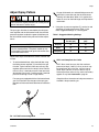
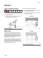
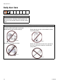
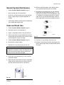
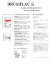
1
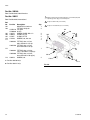
Instructions - Parts
Automatic XT Spray Guns
311051D
Airspray, HVLP, and Compliant guns for spraying paints and coatings.
See page 3 for model information.
100 psi (0.7 MPa, 7 bar) Maximum Working Fluid Pressure
100 psi (0.7 MPa, 7 bar) Maximum Working Air Pressure
Important Safety Instructions
Read all warnings and instructions in this manual.
Save these instructions.
TI8169a
Part No. 249377 Airspray Gun with fluid control
shown mounted on Part No. 288223 Manifold.
TI8085a
Part No. 249369 Airspray Gun shown mounted on
Part No. 288221 Manifold.
II 2 G c T6
Related Manuals
Contents
Related Manuals . . . . . . . . . . . . . . . . . . . . . . . . . . . 2
Models . . . . . . . . . . . . . . . . . . . . . . . . . . . . . . . . . . . 3
Warnings . . . . . . . . . . . . . . . . . . . . . . . . . . . . . . . . . 4
Selection Charts . . . . . . . . . . . . . . . . . . . . . . . . . . . 6
Proper Needle/Nozzle Selection . . . . . . . . . . . . . 8
Gun Selection . . . . . . . . . . . . . . . . . . . . . . . . . . . 8
Air Flow . . . . . . . . . . . . . . . . . . . . . . . . . . . . . . . . . . 9
Installation . . . . . . . . . . . . . . . . . . . . . . . . . . . . . . . 10
Ventilate Spray Booth . . . . . . . . . . . . . . . . . . . . 10
Configure Gun and Manifold . . . . . . . . . . . . . . . 10
Install Air Fittings . . . . . . . . . . . . . . . . . . . . . . . . 11
Ground System . . . . . . . . . . . . . . . . . . . . . . . . . 11
Mount Gun . . . . . . . . . . . . . . . . . . . . . . . . . . . . 12
Setup . . . . . . . . . . . . . . . . . . . . . . . . . . . . . . . . . . . . 13
Connect Air Line . . . . . . . . . . . . . . . . . . . . . . . . 13
Connect Fluid Hose . . . . . . . . . . . . . . . . . . . . . 13
Flush Spray Gun . . . . . . . . . . . . . . . . . . . . . . . . 14
Position Air Cap . . . . . . . . . . . . . . . . . . . . . . . . 14
Adjust Spray Pattern . . . . . . . . . . . . . . . . . . . . . 15
Operation . . . . . . . . . . . . . . . . . . . . . . . . . . . . . . . . 17
Pressure Relief Procedure . . . . . . . . . . . . . . . . 17
Apply Fluid . . . . . . . . . . . . . . . . . . . . . . . . . . . . . 17
Daily Gun Care . . . . . . . . . . . . . . . . . . . . . . . . . . . . 18
General System Maintenance . . . . . . . . . . . . . . 19
Clean and Flush Gun . . . . . . . . . . . . . . . . . . . . . 19
Troubleshooting . . . . . . . . . . . . . . . . . . . . . . . . . . . 20
General Troubleshooting . . . . . . . . . . . . . . . . . . 20
Spray Pattern Troubleshooting . . . . . . . . . . . . . 22
Service . . . . . . . . . . . . . . . . . . . . . . . . . . . . . . . . . . 23
Replace Fluid Packings and Air Seals . . . . . . . . 23
Reassembly . . . . . . . . . . . . . . . . . . . . . . . . . . . . 25
Parts . . . . . . . . . . . . . . . . . . . . . . . . . . . . . . . . . . . . 26
Accessories . . . . . . . . . . . . . . . . . . . . . . . . . . . . . . 33
Dimensions . . . . . . . . . . . . . . . . . . . . . . . . . . . . . . . 34
Mounting Hole Layout . . . . . . . . . . . . . . . . . . . . . . 35
Mounting Hole Layout . . . . . . . . . . . . . . . . . . . . . . 36
Technical Data . . . . . . . . . . . . . . . . . . . . . . . . . . . . 37
Graco Standard Warranty . . . . . . . . . . . . . . . . . . . 38
Graco Information . . . . . . . . . . . . . . . . . . . . . . . . . 38
Related Manuals
The Automatic XT Spray Guns manual is available in the following languages. See the following chart for specific language and part number.
2
Manual
Language
311644
Japanese
Manual
Language
311051
English
311645
Korean
311637
Chinese
311646
Norwegian
311638
Danish
311647
Polish
311639
Dutch
311648
Russian
311640
Finnish
311649
Spanish
311641
French
311650
Swedish
311642
German
311643
Italian
311051D
Models
Models
A manifold is required for each gun to be installed.
Refer to the Parts section for manifold information.
Orifice Size
in. (mm)
HVLP
Compliant
Airspray
.030 (0.75)
249388
249407
249369
.042 (1.0)
249389
249408
249370
.055 (1.4)
249390
249409
249371
.070 (1.8)
249391
249410
249372
*.042 (1.0) Hardened SST
249394
288049
249375
*.055 (1.4) Hardened SST
249395
288050
249376
.030 (0.75) with Fluid Control Knob
249396
249411
249377
.042 (1.0) with Fluid Control Knob
249397
249412
249378
.055 (1.4) with Fluid Control Knob
249398
249413
249379
.070 (1.8) with Fluid Control Knob
249399
249414
249380
* Hardened SST needle tip/nozzle (not recommended for thin fluids). All other models have PEEK needle tip.
311051D
3
Warnings
Warnings
The following warnings are for the setup, use, grounding, maintenance, and repair of this equipment. The exclamation point symbol alerts you to a general warning and the hazard symbol refers to procedure-specific risk. Refer back
to these warnings. Additional, product-specific warnings may be found throughout the body of this manual where
applicable.
WARNING
EQUIPMENT MISUSE HAZARD
Misuse can cause death or serious injury.
• Do not operate the unit when fatigued or under the influence of drugs or alcohol.
• Do not exceed the maximum working pressure or temperature rating of the lowest rated system
component. See Technical Data in all equipment manuals.
• Use fluids and solvents that are compatible with equipment wetted parts. See Technical Data in all
equipment manuals. Read fluid and solvent manufacturer’s warnings. For complete information
about your material, request MSDS forms from distributor or retailer.
• Check equipment daily. Repair or replace worn or damaged parts immediately with genuine manufacturer’s replacement parts only.
• Do not alter or modify equipment.
• Use equipment only for its intended purpose. Call your distributor for information.
• Route hoses and cables away from traffic areas, sharp edges, moving parts, and hot surfaces.
• Do not kink or over bend hoses or use hoses to pull equipment.
• Keep children and animals away from work area.
• Comply with all applicable safety regulations.
FIRE AND EXPLOSION HAZARD
Flammable fumes, such as solvent and paint fumes, in work area can ignite or explode. To help prevent
fire and explosion:
• Use equipment only in well ventilated area.
• Eliminate all ignition sources; such as pilot lights, cigarettes, portable electric lamps, and plastic drop
cloths (potential static arc).
• Keep work area free of debris, including solvent, rags and gasoline.
• Do not plug or unplug power cords, or turn power or light switches on or off when flammable fumes
are present.
• Ground all equipment in the work area. See Grounding instructions.
• Use only grounded hoses.
• Hold gun firmly to side of grounded pail when triggering into pail.
• If there is static sparking or you feel a shock, stop operation immediately. Do not use equipment
until you identify and correct the problem.
• Keep a working fire extinguisher in the work area.
PRESSURIZED EQUIPMENT HAZARD
Fluid from the gun/dispense valve, leaks, or ruptured components can splash in the eyes or on skin and
cause serious injury.
• Follow Pressure Relief Procedure in this manual, when you stop spraying and before cleaning,
checking, or servicing equipment.
• Tighten all fluid connections before operating the equipment.
• Check hoses, tubes, and couplings daily. Replace worn or damaged parts immediately.
4
311051D
Warnings
WARNING
TOXIC FLUID OR FUMES HAZARD
Toxic fluids or fumes can cause serious injury or death if splashed in the eyes or on skin, inhaled, or
swallowed.
• Read MSDS’s to know the specific hazards of the fluids you are using.
• Store hazardous fluid in approved containers, and dispose of it according to applicable guidelines.
PERSONAL PROTECTIVE EQUIPMENT
You must wear appropriate protective equipment when operating, servicing, or when in the operating
area of the equipment to help protect you from serious injury, including eye injury, inhalation of toxic
fumes, burns, and hearing loss. This equipment includes but is not limited to:
• Protective eyewear
• Clothing and respirator as recommended by the fluid and solvent manufacturer
• Gloves
• Hearing protection
311051D
5
Selection Charts
Selection Charts
TERMS:
Light Fluid: Up to 18 seconds with No. 2 Zahn cup (20
centipoise)
Medium Fluid:19 to 28 seconds with No. 2 Zahn cup
(20-64 centipoise)
Heavy Fluid:Greater than 28 seconds with No. 2 Zahn
cup (greater than 64 centipoise) -- 2.8 Volatile Organic
Compounds, High-solid Polyurethanes, Heavy Waterborne Enamels
HVLP Spray Gun Assemblies
Includes:
Gun Assy.
Needle/
Nozzle Kit
Part No.
Material Usage
321 Air Cap
Orifice Size
Viscosity
Flow
Part No.
Reorder
Part No.
in. (mm)
249388
15F829
288134
.030 (0.75)
light
4-10 (0.12-0.30)
249389
15F830
288134
.042 (1.0)
light-medium
8-14 (0.24-0.42)
249390
15F831
288134
.055 (1.4)
medium
12-18 (0.36-0.54)
oz./min. (l/min.)
249391
15F832
288134
.070 (1.8)
medium-heavy
16-20 (0.48-0.60)
249394*
15F835*
288134
.042 (1.0)
light-medium
8-14 (0.24-0.42)
249395*
15F836*
288134
.055 (1.4)
medium
12-18 (0.36-0.54)
249396†
15F829
288134
.030 (0.75)
light
4-10 (0.12-0.30)
249397†
15F830
288134
.042 (1.0)
light-medium
8-14 (0.24-0.42)
249398†
15F831
288134
.055 (1.4)
medium
12-18 (0.36-0.54)
249399†
15F832
288134
.070 (1.8)
medium-heavy
16-20 (0.48-0.60)
* Hardened SST needle tip/nozzle (not recommended for thin fluids). All other models have PEEK needle tip.
† With Fluid Control Knob (for fine adjustment of fluid flow).
6
311051D
Selection Charts
Compliant Spray Gun Assemblies
Includes:
Gun Assy.
Needle/
Nozzle Kit
Part No.
Material Usage
006 Air Cap
Orifice Size
Part No.
Reorder
Part No.
in. (mm)
249407
15F829
288132
.030 (0.75)
light
4-10 (0.12-0.30)
249408
15F830
288132
.042 (1.0)
light-medium
8-14 (0.24-0.42)
249409
15F831
288132
.055 (1.4)
medium
12-18 (0.36-0.54)
Viscosity
Flow
oz./min. (l/min.)
249410
15F832
288132
.070 (1.8)
medium-heavy
16-20 (0.48-0.60)
288049*
15F835*
288132
.042 (1.0)
light-medium
8-14 (0.24-0.42)
288050*
15F836*
288132
.055 (1.4)
medium
12-18 (0.36-0.54)
249411†
15F829
288132
.030 (0.75)
light
4-10 (0.12-0.30)
249412†
15F830
288132
.042 (1.0)
light-medium
8-14 (0.24-0.42)
249413
15F831
288132
.055 (1.4)
medium
12-18 (0.36-0.54)
249414†
15F832
288132
.070 (1.8)
medium-heavy
16-20 (0.48-0.60)
* Hardened SST needle tip/nozzle (not recommended for thin fluids). All other models have PEEK needle tip.
† With Fluid Control Knob (for fine adjustment of fluid flow).
Airspray Gun Assemblies
Includes:
Gun Assy.
Needle/
Nozzle Kit
Part No.
Material Usage
315 Air Cap
Orifice Size
Viscosity
Flow
Part No.
Reorder
Part No.
in. (mm)
249369
15F829
288133
.030 (0.75)
light
249370
15F830
288133
.042 (1.0)
light-medium
8-14 (0.24-0.42)
249371
15F831
288133
.055 (1.4)
medium
12-18 (0.36-0.54)
249372
15F832
288133
.070 (1.8)
medium-heavy
16-20 (0.48-0.60)
249375*
15F835*
288133
.042 (1.0)
light-medium
8-14 (0.24-0.42)
oz./min. (l/min.)
4-10 (0.12-0.30)
249376*
15F836*
288133
.055 (1.4)
medium
12-18 (0.36-0.54)
249377†
15F829
288133
.030 (0.75)
light
4-10 (0.12-0.30)
249378†
15F830
288133
.042 (1.0)
light-medium
8-14 (0.24-0.42)
249379†
15F831
288133
.055 (1.4)
medium
12-18 (0.36-0.54)
249380†
15F832
288133
.070 (1.8)
medium-heavy
16-20 (0.48-0.60)
* Hardened SST needle tip/nozzle (not recommended for thin fluids). All other models have PEEK needle tip.
† With Fluid Control Knob (for fine adjustment of fluid flow).
311051D
7
Selection Charts
Proper Needle/Nozzle Selection
Gun Selection
The spray gun's needle/nozzle kits range in size to provide different fluid flow rates.
HVLP Guns
As a general guideline, use the fluid nozzle that will give
the required flow with the needle fully triggered at a fluid
pressure of 5-20 psi (0.035 MPa, 3.5 bar - 0.14 MPa. 14
bar)
For low flow rates or light viscosity fluid, select the
smaller nozzle sizes.
For high flow rates or high viscosity fluid, select the
larger nozzle sizes.
For thicker, abrasive fluids, hardened SST needle tips
and nozzles are recommended.
An HVLP gun is a high transfer efficiency gun that limits
the air pressure at the air cap to 10 psi (0.07 MPa, 0.7
bar) maximum. In some areas, an HVLP gun is required
for compliance with environmental standards.
Compliant Guns
A compliant gun is a high transfer efficiency gun that has
been tested to have a transfer efficiency greater than or
equal to HVLP guns. In addition, the compliant air cap
consumes much less air than the HVLP air cap.
The Graco compliant guns have no restrictions on air
cap pressures, but the gun inlet pressure must remain
under 30 psi (0.21 MPa, 2.1 bar) to remain in compliance.
Airspray Guns
An airspray gun has excellent atomization and high production rates typically with some reduction in transfer
efficiency.
Air Caps
The chart below lists the air caps available for pressure
feed, gravity, and siphon feed guns.
Spray Gun
Air Cap ID
Typical Pattern
Width*
in. (mm)
HVLP
321A
15 (381)
Pressure Feed
.030-.070
(.75-1.8)
288134
HVLP
322
15 (381)
Pressure Feed
.086 (2.2)
234754†
HVLP
323
15 (381)
Pressure Feed
.110 (2.8)
234755†
Compliant
006A
11 (279)
All Models
.030-.070
(.75-1.8)
288132
Airspray
315A
13 (330)
Pressure Feed
.030-.070
(.75-1.8)
288133
Airspray
318
10 (254)
Pressure Feed
.086 (2.2)
234760†
Airspray
319
10 (254)
Pressure Feed
.110 (2.8)
234761†
Airspray
313
10 (254)
Pressure Feed
.030-.070
(.75-1.8)
234756†
Airspray
316
10 (254)
Pressure Feed
.030-.070
(.75-1.8)
234758†
Gun Feed
Nozzle Orifice
in. (mm)
Part Number
* Measured with gun nozzle 8 in. (203 mm) from target surface.
† Caps do not have alignment pin feature.
8
311051D
Air Flow
Air Flow
All tests were completed with the 0.055 in. (1.4
mm) nozzle and standard air cap for each gun
model.
HVLP Aircap Pressures
12
11
Aircap Pressure in psi
10
9
8
HVLP Atomization Air
Pressure at Cap
7
6
HVLP Fan Air Pressure at
Cap
5
4
3
2
1
0
0
5
10
15
20
25
30
35
40
45
50
Manifold Inlet Pressure psi
FIG. 1: HVLP Gun Air Cap Pressure
Automatic Gun Air Consumption
20
18
Air Flow in SCFM
16
14
Airspray Atom. Flow
12
HVLP Atom. Flow
Compliant Atom. Flow
10
Airspray Fan Flow
8
HVLP Fan Flow
6
Compliant Fan Air Flow
4
2
0
0
10
20
30
40
50
60
Manifold Inlet Pressure psi
FIG. 2: Automatic Gun Air Consumption
311051D
9
Installation
Installation
The Automatic XT spray guns were designed to produce
the highest quality finish with today's fluids as well as
the low V.O.C. (volatile organic compound) fluids of
tomorrow.
This spray gun can spray most coatings or finishes currently being used for automotive, industrial, aerospace,
marine, wood, plastic and architectural applications,
while easily operating from paint delivery systems, such
as pressure pots or remote pumps for production line
operation.
The air regulator must have a minimum air flow capacity
of 30 scfm at 100 psi (0.7 MPa, 7 bar) air pressure.
Ventilate Spray Booth
Non-circulating System
1. See FIG. 3. See Apply anti-seize lubricant 222955 to
the threads and mating faces of the manifold (101),
plug (109), and elbow (107), supplied unassembled.
2. Install an elbow (107) in one fluid port of the manifold (101), and a plug (109) in the other port.
3. Install the internal plug (5) in the gun fluid port on
the same side as the manifold plug.
4. Connect the fluid supply line to the fluid inlet elbow
(107).
5. Install the gun on the manifold, using the four
screws (13). Start the threads of all four screws.
Tighten the front two screws first, and then tighten
the back two. Torque all four screws evenly to 65
in-lb (7.3 N•m).
Check and follow all National, State, and Local
codes regarding air exhaust velocity requirements.
1
Remove when used in circulating systems.
2
Replace with elbow (107) when used in circulating systems.
Check and follow all local safety and fire codes.
21
Configure Gun and Manifold
20
The gun is supplied with an internal fluid plug and seals
(19, 20, 21). To use the gun in a circulating system,
remove the internal plug. In a non-circulating system,
leave the plug in place to minimize flush time.
1
2
Circulating System
1. Apply anti-seize lubricant to the threads and mating
faces of the manifold (101) and the elbows (107),
supplied unassembled.
19
109
101
107
TI8587b
FIG. 3: Non-Circulating Setup Shown (cutaway view)
2. Install the elbows (107) in both fluid ports of the
manifold (101).
3. Connect the fluid supply line to one elbow and the
fluid return line to the other. The manifold fluid ports
are reversible.
4. Install the gun on the manifold, using the four
screws (13). Start the threads of all four screws.
Tighten the front two screws first, and then tighten
the back two. Torque all four screws evenly to 65
in-lb (7.3 N•m).
10
311051D
Installation
Install Air Fittings
Ground Fluid Supply Container
1. Install the supplied 1/4 in. tube fitting into the cylinder (CYL) air port.
2. Install 3/8 in. tube fittings into the atomization
(ATOM) air port and the fan (FAN) air port.
CYL
Ground Object Being Sprayed
Ground the object that is being sprayed according to
local code.
Ground Solvent Pails
Ground all solvent pails that are used when flushing
according to local code. Use only metal pails, which are
conductive. Do not place the pail on a non-conductive
surface, such as paper or cardboard, which interrupts
the grounding continuity.
ATOM
FAN
Ground the fluid supply container according to local
code.
TI8211a
FIG. 4: Air Fittings
Ground System
The following grounding instructions are minimum
requirements for a system. Your system may include
other equipment or objects that must be grounded.
Check your local electrical code for detailed grounding
instructions for your area and type of equipment. Your
system must be connected to a true earth ground.
Ground Pump/Fluid Supply
Ground the pump by connecting a ground wire and
clamp between the fluid supply and a true earth ground
as instructed in your separate pump instruction manual.
Ground Air Compressors and Hydraulic
Power Supplies
Ground the air compressors and hydraulic power supplies according to the manufacturer recommendations.
Ground Spray Gun
Ground the spray gun by mounting the manifold to a
properly grounded reciprocator, robot, or stationary
mount. Check the electrical resistance between the
manifold and a true earth ground. The resistance must
be less than 1 megohm.
311051D
11
Installation
Mount Gun
2. Secure the gun to the support with two M5 x 0.8
capscrews (C). The screws must be long enough to
engage the threaded holes in the gun manifold to a
depth of 1/4 in. (6 mm).
Reciprocating Arm Rod Mount
To mount the gun on a reciprocating arm rod [0.5 in. (13
mm) diameter maximum]:
1. Insert the mounting bar (A) through the hole in the
manifold as shown in FIG. 5.
Use the 1/8 in. alignment pin (P) to assist in orienting the gun.
2. Secure the gun to the bar by tightening the mounting screw (B).
C
TI8095 a
B
FIG. 6: Stationary Support Mount
P
Retrofit Adapter Plate
The retrofit adapter plate enables the manifold to be
attached to a variety of bolt patterns.
To mount the gun using the retrofit adapter plate (kit
288197):
A
FIG. 5: Reciprocating Arm Mount
TI8094a
Stationary Support
1. Mount adapter plate to manifold using the three
screws provided with the kit (FIG. 7).
2. Bolt plate to mounting surface using four M5 x 0.8
capscrews. Refer to the Mounting Hole Layout,
page 36.
To mount the gun on a stationary support (refer to FIG. 6
and Mounting Hole Layout, page 35):
1. Align the manifold with the alignment pins. Locate
alignment pins and holes per the Mounting Hole
Layout illustration, page 35.
TI8180a
FIG. 7: Retrofit Adapter Plate Mount
12
311051D
Setup
Setup
Connect Air Line
Connect Fluid Hose
You must install an air pressure regulator (F) on
each gun air line to control air pressure to the gun.
See FIG. 8.
If your regulated air source does not have a filter,
install an air filter (G) on each air line to ensure a
dry, clean air supply to the gun. Dirt and moisture
can ruin the appearance of your finished workpiece. See FIG. 8.
Install a bleed type air shutoff valve (E) on each
gun air supply line, downstream of the gun air regulator, to shut off air to the gun.
1. For manifolds with a separate ATOM and FAN port,
the gun cylinder, fan, and atomization air must be
supplied and regulated separately. For the manual
fan valve manifold, only one supply line is required
for both atomization and fan air.
The gun atomizing and fan air inlets are 3/8 in. O.D.
tubing. The cylinder air inlet accepts 1/4 in. (6.3
mm) O.D. tubing. Use 3/8 in. (9.5 mm) O.D. tubing
for fan and atomization air to minimize excessive
pressure drop in the hoses.
Before connecting the fluid line, blow it out with air
and flush it with solvent. Use solvent that is compatible with the fluid to be sprayed.
Install a fluid regulator (L) on the fluid line to control
fluid pressure to the gun. See FIG. 9.
Install a fluid shutoff valve (M) to shut off the fluid
supply to the gun. See FIG. 9.
Filter the fluid line of coarse particles and sediment
to avoid clogging the fluid nozzle and causing finishing defects.
1. Connect the fluid supply hose (J) to the gun fluid
inlet (S) 1/4 npsm thread. See FIG. 10.
2. Connect the other end of the fluid hose (J) to a regulated fluid supply outlet (M). See FIG. 9.
3. In a circulating system, connect a grounded fluid
return hose to the gun fluid outlet (T). See FIG. 10.
In a non-circulating system, remove the gun fluid
outlet fitting (T) and plug the outlet port with the pipe
plug supplied. See FIG. 10.
2. Connect each air hose (D) to a regulated air supply
line (H).
F
L
K
D
M
H
J
G
E
TI01990
FIG. 8: Connect Air Line
TI7016a
FIG. 9: Connect Fluid Hose
311051D
13
Setup
Flush Spray Gun
KEY
N Cylinder Air Inlet: accepts 1/4 in. (6.3 mm) O.D. tubing
P Atomization Air Inlet: 3/8 in, (9.5 mm) O.D. tubing
R Fan Air Inlet: 3/8 in. (9.5 mm) O.D, tubing
S Fluid Inlet: 1/4 npsm
T Fluid Outlet (circulating gun only): 1/4 npsm
Before running any paint through the spray gun:
Side Mounted Manifold Ports
1. Flush the gun with a solvent that is compatible with
the fluid to be sprayed, using the lowest possible
fluid pressure and a grounded metal container.
2. Perform Pressure Relief Procedure; see page 17.
N
T (or S)
S (or T)
FAN
ATOM
Position Air Cap
Air caps are factory-set with the alignment pin (A) set to
a vertical spray pattern. To change the air cap to a horizontal spray pattern, use a needle nos pliers to unscrew
the alignment pin (A) and relocate it to the horizontal
spray pattern hole. When relocating the pin use low
strength thread locker. Torque to 1.5-2.5 in-lb (0.2-0.3
N•m). Do not overtighten. Refer to FIG. 11.
CYL
TI8096a
R
P
Bottom Mounted Manifold Ports
TI8171a
Vertical Pattern
A
TI8170a
N
TI8172a
Horizontal Pattern
FIG. 11: Position Air Cap
R
FAN
ATOM
P
CYL
T (or S)
S (or T)
TI8097a
FIG. 10: Manifold Ports
14
311051D
Setup
Adjust Spray Pattern
Do not exceed 100 psi (0.7 MPa, 7 bar) maximum fluid
and air pressure. Higher pressures can cause parts to
rupture and result in serious injury.
The spray gun fluid flow is controlled by the fluid pressure regulator and the fluid control knob. Use the fluid
pressure regulator to adjust the general fluid flow and
the fluid control knob to make precise fluid flow adjustments.
CAUTION
Use caution when operating the fluid control valve
near the closed position. The plastic needle tip may
be damaged if forced too hard against the nozzle seat
by the fluid control valve.
A larger fluid nozzle at a reduced fluid pressure will
maintain the same flow rate, but the fluid stream
(velocity) will slow down. When air is applied, this
allows air to act on the fluid longer and improve the
atomization.
2. Using the air pressure regulator (F), set the fan and
atomizing air supply pressure per Table 1. Use
these suggested settings as a starting point.
Table 1: Suggested Starting Settings
Fan Air (psi)
Atomization Air
(psi)
Airspray
35
35
HVLP
25
25
Compliant
18
25
Follow these steps to establish the correct fluid flow and
air flow:
HVLP and Compliant Gun Limits
1. To achieve desired flow, adjust the fluid flow using
the fluid pressure regulator (L) installed in the gun
fluid line. Typical industrial flow rates will vary with
regulator pressures from 5 to 30 psi (34 to 210 kPa,
0.3 to 2.1 bar). If the fluid pressure is too low at the
desired flow rate, install a smaller nozzle. If the fluid
pressure is too high, install a larger nozzle.
For spray guns equipped with the fluid control knob,
you can make flow rate changes at the spray gun.
Rotate the fluid control knob clockwise to reduce the
flow.
HVLP Guns: local laws may limit the maximum
pressure to 10 psi (70 kPa, 0.7 bar) at the air cap
for compliance. 35 psi (25 kPa, 2.5 bar) inlet air
yields 10 psi (70 kPa, 0.7 bar) at the air cap. To
measure pressure at the air cap, use the accessory
tapped air cap. See Accessories, page 33.
Compliant Guns: the maximum inlet pressure to the
manifold is 30 psi atomizing air.
L
TI7019a
FIG. 12: Fluid Pressure Regulator
311051D
15
Setup
F
TI01997
FIG. 13: Air Pressure Regulator
3. Test the spray pattern atomization while keeping the
gun a consistent distance, about 6 to 8 inches (150
to 200 mm), from the test piece.
Check the atomization quality. Increase the gun
atomizing air supply pressure with the air pressure
regulator in 5 psi (34 kPa, 0.3 bar) increments until
you obtain the desired atomization.
For the best transfer efficiency, use the lowest setting needed to achieve desired finish quality.
4. If the spray pattern is too wide or split, reduce the
fan air pressure (or slightly close the fan adjustment
valve on manifold 288223).
To further control the spray pattern of airspray guns
only, use an alternate air cap. For a list of available
air caps, refer to Accessories, page 33.
Reducing the fan air pressure to 0 psi (or fully closing the fan adjustment valve) will produce a round
pattern.
16
311051D
Operation
Operation
Pressure Relief Procedure
1. Turn off all bleed type air valves and all other air and
fluid supplies to the gun.
2. Trigger the gun into a grounded metal waste container to relieve air and fluid pressure.
To achieve best results when applying fluid:
•
Keep gun perpendicular and 6 to 8 in. (150 to 200
mm) from object being sprayed.
•
Use smooth, parallel strokes across surface to be
sprayed with 50% overlap.
Incorrect
TI8174a
FIG. 14: Pressure Relief
Apply Fluid
TI8098a
Correct
The spray gun has a built-in lead and lag operation.
When triggered, the gun begins emitting air before the
fluid is discharged. When the trigger actuation air is
stopped, the fluid stops before the air flow stops. This
helps ensure that the spray is atomized and prevents
fluid buildup on the air cap and tip.
Adjust the system control device, if it is automatic, so the
gun starts spraying just before meeting the part and
stops as soon as the part has passed. Keep the gun a
consistent distance, 6 to 8 in. (150 to 200 mm), from the
surface of the object being sprayed.
TI8099a
FIG. 15: Correct Spray Method
311051D
17
Daily Gun Care
Daily Gun Care
CAUTION
Methylene chloride with formic or propionic acid is not
recommended as a flushing or cleaning solvent with
this gun as it will damage aluminum and nylon components.
CAUTION
Solvent left in gun air passages could result in a poor quality paint finish. Do not use any cleaning method which
may allow solvent into the gun air passages.
Do not point the gun up while cleaning it.
Do not wipe the gun with a cloth soaked in solvent;
ring out the excess.
TI8100a
TI4827a
Do not immerse the gun in solvent.
Do not use metal tools to clean the air cap holes as
this may scratch them; scratches can distort the
spray pattern.
TI8101a
TI8175a
18
311051D
Daily Gun Care
General System Maintenance
•
Perform Pressure Relief Procedure, page 17.
•
Clean the fluid and air line filters daily.
•
Check for any fluid leakage from the gun and fluid
hoses. Tighten fittings or replace equipment as
needed.
•
Flush the gun before changing colors and whenever
you are done operating the gun.
10. With the gun pointed down, clean the front of the
gun, using the soft-bristle brush and solvent.
11. Scrub the air cap retaining ring, air cap, and fluid
nozzle with the soft-bristle brush (see FIG. 17). To
clean out air cap holes, use a soft implement, such
as a toothpick, to avoid damaging critical surfaces.
Clean the air cap and fluid nozzle daily, minimum.
Some applications require more frequent cleaning.
Clean and Flush Gun
1. Perform Pressure Relief Procedure, page 17.
2. Shut off the gun fan and atomizing air.
3. Supply a compatible solvent to the gun fluid inlet.
TI8176a
4. Point the gun down into a grounded metal container,
and flush the gun with solvent until all traces of paint
are removed from the gun passages.
FIG. 17:
5. Perform Pressure Relief Procedure, page 17.
12. Install the air cap retaining ring and air cap.
6. Disconnect the solvent supply.
13. Dampen a soft cloth with solvent and wring-out the
excess. Point the gun down and wipe off the outside
of the gun.
7. Remove the air cap retaining ring and air cap.
CAUTION
Trigger the gun or remove the piston cap whenever
you tighten or remove the nozzle. This keeps the needle seat away from the nozzle seating surface and
prevents the seat from being damaged.
8. Clean the air cap retaining ring, air cap, and fluid
nozzle with solvent.
9. Dip the end of a soft-bristle brush into a compatible
solvent. Do not continuously soak the brush's bristles with solvent and do not use a wire brush.
TI4845a
FIG. 16:
311051D
19
Troubleshooting
Troubleshooting
Check all possible remedies in the troubleshooting
charts before disassembling the gun.
Some improper patterns are caused by the
improper balance between air and fluid. Refer to
Spray Pattern Troubleshooting, page 22.
General Troubleshooting
Problem
Fluid leakage through venting holes.
Cause
Worn packing (17) or needle (5).
Solution
Replace packing or needle.
Air leakage through venting hole.
Worn o-ring (9) or gasket (15).
Check and replace parts as needed.
Air leakage from back of gun.
Worn o-rings (8, 9).
Replace o-rings.
Air does not trigger.
Piston stem is disconnected from
main body of piston assembly (3).
Replace piston assembly.
Cylinder air pressure is too low.
Increase cylinder air pressure to 50
psi.
Air does not shut off.
Fluid leakage from front of gun.
Piston assembly not seating properly. Clean/service piston assembly.
Replace worn or swollen o-rings.
Broken return spring (7).
Replace return spring.
Swollen o-ring (8).
Replace o-rings.
Worn piston stem o-rings (10, 11).
Replace o-rings.
Bottom gasket (12) failed.
Replace gasket.
Fluid needle tip (5a) is dirty, worn, or Clean or replace fluid needle tip or
damaged.
entire needle (5).
Dirty or worn nozzle (23).
Fluid is present at air cap holes.
20
Clean or replace nozzle.
Nozzle (23) is insufficiently tightened Tighten or replace o-ring.
or sealing o-ring (36) is damaged.
311051D
Troubleshooting
Problem
Fluid needle will not trigger.
Fluid does not shut off.
311051D
Cause
Solution
Loose or missing fluid needle stop
(29) or setscrew (30).
Replace stop or tighten setscrew.
Air leaking around piston (3).
Replace o-ring (8) or piston.
Swollen piston o-ring (8).
Replace o-ring. Do not immerse piston in solvent.
Insufficient air pressure on trigger.
Increase air pressure or clean air
line.
Plug (19) is in incorrect fluid port.
Move plug to fluid port consistent with
manifold plumbing, unless you are
using gun in a circulating system. If
you are, all fluid ports in gun and on
manifold should be open.
Worn o-ring (11) or (9).
Replace o-ring.
Piston cap (4) not fully tightened.
Tighten piston cap until it bottoms
out.
Spring (6) not in place.
Check spring position.
Swollen piston o-ring (8).
Replace o-ring. Do not immerse piston in solvent
21
Troubleshooting
Spray Pattern Troubleshooting
Problem
Cause
Fluid flow is fluttering while spraying. Fluid nozzle is not tight enough.
Solution
Tighten fluid nozzle to 60 in-lb (6.8
N•m).
O-ring (36) is missing or damaged.
Replace o-ring.
Fluid filter is clogged.
Check fluid filter.
Fluid flow fades while spraying high
viscosity fluids.
Fluid pressure is too low, causing
fluid flow to reduce when gun is elevated.
Raise fluid pressure at source or use
a smaller fluid nozzle.
Pattern becomes off-set of heavy on
ends.
Air cap horn holes plugged or damaged.
Clean air cap horn holes with
non-metallic item such as a toothpick,
or replace air cap.
Gun fluid pressure is too high with
gun triggered.
Using needle/nozzle kit with too small Use needle/nozzle kit with larger oriorifice.
fice.
Fluid system will not operate at low
enough fluid pressure [below 10 psi
(70 kPa, 0.7 bar)].
There is no fluid regulator, or air reg- Add low pressure fluid regulator, or
ulator on pressure pot is not sensitive add more sensitive low pressure air
enough at low pressures.
regulator on pressure pot.
22
311051D
Service
Service
5. Using a 1/16 in. hex wrench loosen the fluid needle
set screw (30). Remove the needle stop (29).
Items Needed for Service
•
1/16 in. Hex Wrench - provided
•
3 mm Hex Wrench
•
Adjustable Wrench
•
4 mm Hex Wrench
•
Pliers
•
Lubricant part no. 111265; see Accessories, page
33, to order
•
Compatible Solvent
6. Pull the fluid needle (5) out the back of the gun.
7. Check the fluid needle (5) for damage or excessive
wear. Replace the needle tip (5a) or the entire needle if necessary.
8. Remove nozzle (23). Check nozzle and o-ring (36)
for damage. You may need to use a pick to remove
o-ring from housing (2).
Replace Fluid Packings and Air
Seals
36
TI8198a
Air Section Repair Kit 288171 and Fluid Section
Repair Kit 288135 are available. Purchase the kits
separately.
1. Perform Pressure Relief Procedure, page 17.
2. Unscrew the four screws (13) and remove the gun
from the manifold.
FIG. 19
9. Remove the piston. Using a pliers, pull the piston (3)
out of the piston housing (1). See FIG. 20.
10. Unscrew the two screws (14) and separate the fluid
housing (2) and the piston housing (1). Remove
gasket (12) only if it needs to be replaced. See FIG.
20.
3. Remove the air cap retainer (25) and air cap (24).
See FIG. 18.
14
23
2
4
13
14
1
24, 25
TI8102a
FIG. 18
4. Remove the piston cap (4) from the piston housing
(1). Remove the springs (6, 7).
311051D
TI8173a
FIG. 20
11. Remove the packing nut (16) with a wrench.
12. Remove the fluid packing (17) from the nut (16).
Discard the old fluid packing.
23
Service
b.
13. Remove all o-rings from the piston (3) and stems
(T). Check that the stems are solidly in place. If they
are loose, replace the entire piston assembly (3).
15. Clean all parts and replace any worn parts. When
assembling, lubricate the threads with anti-seize
lubricant.
14. Perform the following applicable step:
a. Non-circulating guns: Remove the fluid outlet
port plug (19), and gasket (22) from the fluid
housing (2). Remove the o-ring (21) and backup
(20) from the plug.
1
Circulating guns: Remove the gasket (22) from
the fluid housing (2).
2
4
8* 3
T
2
4
6
11* 3
2
16
25
23
1
10*
2
3
8
2
7
24
29
30
9
5a
9
7
3
3
17
6
3
12*
TI8103a
3
5
Cutaway View:
Part No. 249388 Gun Shown
36
SERVICE NOTES:
1
Torque to 35-45 in-lb (4.0-5.1 N•m)
2
Lubricate threads with anti-seize lubricant
3
Lubricate with light-weight oil
4
Tighten cap (4) until it bottoms out
6
Apply semi-permanent anaerobic sealant
7
Torque to 4-5 in-lb (0.45-0.57 N•m)
8
Torque to 95-105 in-lb (10.7-11.8 N•m)
9
Apply semi-permanent anaerobic sealant to two
threads at end of needle shaft.
TI8199a
Alternate Fluid Control Shown
FIG. 21
24
311051D
Service
Reassembly
1. Non-circulating guns only: Lubricate the backup ring
(20†) and o-ring (21†) and install them on the fluid
outlet port plug (19). Install the plug in the fluid outlet port of the fluid housing (2). See FIG. 22.
2. All guns: Reinstall the gasket (22) in the fluid housing (2).
3. Install the o-rings (8*, 9*) on the piston (3). Install
the two o-rings (10*, 11*) on each of the piston
stems (T). Lubricate all the o-rings, the piston, and
the piston stems.
4. Remove the protective paper from the sticky side of
the gasket (12*) and adhere the gasket to the bottom of the piston housing (1), making sure the three
holes in the gasket are properly aligned with the
matching holes in the housing.
ant and install the screw into the needle stop.
Torque to 4-5 in-lb (0.45-0.56 N•m). Pull on the needle to make sure it seats fully.
10. Install the springs (6, 7).
11. Lubricate the threads of the piston housing (1).
Screw the cap (4) onto the housing until it bottoms
out.
12. Install the air cap (24) and air cap retainer (25).
13. Reinstall the gun on the manifold using the four
screws (13). Start the threads of all four screws.
Tighten the front two screws first, and then tighten
the back two. Torque all four screws evenly to 65
in-lb (7.3 N•m).
5. Lubricate the new fluid packing (17†) and insert it
into the packing nut (16). Insert the packing nut into
the fluid housing (2) and torque to 95-105 in-lb
(10.7-11.8 N•m).
6. Align the gasket (15*) as shown in the exploded
view in FIG. 22. Place the gasket on the piston housing (1), then install the fluid housing (2) onto the piston housing. Torque the two screws (14) to 30 in-lb
(3.4 N•m).
a. Insert the piston (3) into the piston housing (1).
b.
Ensure nozzle sealing o-ring (36) is installed in
fluid housing (2).
7. To avoid galling of the fluid nozzle seat in the fluid
housing, apply a thin film of lubricant to the threads.
Install the nozzle into the fluid housing. Torque the
nozzle securely to 60 in-lb (6.8 N•m).
If you are replacing the needle tip (5a), apply
semi-permanent anaerobic sealant to two threads
at the end of the needle shaft. Assemble the needle
tip to the shaft and hand tighten. Allow adequate
time for the sealant to cure before installing the
needle assembly into the gun.
8. Lubricate and install the needle (5) into the back of
the gun assembly. Push it straight in through the piston.
9. Install the needle stop (29) on the needle. Coat the
setscrew (30) with semi-permanent anaerobic seal311051D
25
Parts
Parts
16
17†
8
15*
3
13
2
2
Alternate Fluid
Control
5
5a
23
1
21†
9
10
3
4
2
24
20†
39
25
10
3
10
6
19
7
6
22†
36†
8* 3
24a
30
7
T
25a
3
9*
29
13
5 (ref)
14
1
10*
3
11* 3
3
3
2
TI8086a
12*
SERVICE NOTES:
1
Torque to 35-45 in-lb (4.0-5.1 N•m)
2
Lubricate threads with anti-seize lubricant
3
Lubricate with light-weight oil
4
Tighten cap (4) until it bottoms out
6
Apply semi-permanent anaerobic sealant
7
Torque to 4-5 in-lb (0.45-0.57 N•m)
8
Torque to 95-105 in-lb (10.7-11.8 N•m)
9
Apply semi-permanent anaerobic sealant to two
threads at end of needle shaft.
10
Used on non-circulating guns only
Exploded View:
Part No. 249369 Gun Shown
FIG. 22
26
311051D
Parts
Parts
Ref.
No.
1
2
3
4
5★
5a★
6
7
8*
9*
10*
11*
12*
13
14
15*
16
17†
19
20†
21†
Part No. Description
Qty.
BODY
1
15H321 HOUSING, fluid
1
240895 PISTON, assy
1
CAP, piston
1
192453 standard models
288091 fluid control models
NEEDLE, assy
1
TIP, needle
1
114139 SPRING, compression
1
114138 SPRING, compression
1
115066 PACKING, o-ring, fluoroelastomer
1
111450 PACKING, o-ring, fluoroelastomer
1
111504 PACKING, o-ring, fluoroelastomer
2
112319 PACKING, o-ring, fluoroelastomer
2
114134 GASKET, polyethylene (bottom)
1
15H317 SCREW, mounting manifold (M5)
4
15H318 SCREW, SHC
2
15H316 GASKET, polyethylene (front)
1
195222 NUT, packing
1
115347 PACKING, u-cup
1
192687 PLUG, fluid
1
114340 RING, back-up, PTFE
1
114244 PACKING, o-ring, fluoroelastomer
1
Ref.
No.
22†
23★
24★
24a
25
25a
29
30
34❄
36†
38❄
39
Part No. Description
192443 GASKET, fluid
NOZZLE, fluid, 0.030 in.
CAP, air
288133‡ Airspray (315 cap)
288134‡ HVLP (321 cap)
288132‡ Compliant (006 cap)
15G618 PIN, locating, threaded
239953 RETAINER, ring, assy
192760 PACKING, u-cup
192452 STOP, needle
114137 SCREW, set
114141 WRENCH, hex
113137 PACKING, o-ring
PIN, dowel
15H702 INSERT, plastic
Qty.
2
1
1
2
1
1
1
1
1
1
1
1
★ See spray gun assemblies table (page 28) for part
number.
† Included in Fluid Seal Repair Kit 288135.
* Included in Air Seal Repair Kit 288171.
❄ Not shown.
Air Caps
Orifice Size
Large
Pattern (315)
Air Spray
HVLP
(321)
Compliant
(006)
Medium
Pattern (316)
Air Spray
Small Pattern
(313) Air
Spray
0.030-0.070 (0.8-1.8)
288133
288134
288132
234758
234756
0.086 (2.2)
234760
234754
N/A
N/A
N/A
0.110 (2.8)
234761
234755
N/A
N/A
N/A
311051D
27
Parts
Spray Gun Assemblies (all models)
Item 5
Needle Assy.
Needle/Nozzle Kit
Includes items
Includes item 5a
Gun Part No.
5 & 23
Item 5a
Needle Tip
Item 23
Nozzle
Item 24
Nozzle
Orifice Size
in. (mm)
Pack of 5
249388
249407
249369
249396†
249411†
249377†
15F829
288175
288183
234741
0.030 (0.75)
249388
249407
249369
249397†
249412†
249378†
15F830
288176
288184
234742
0.042 (1.0)
249390
249409
249371
249398†
249413†
249379†
15F831
288177
288185
234744
0.055 (1.4)
249391
249410
249372
249399†
249414†
249380†
15F832
288178
288187
234746
0.070 (1.8)
249394*
288049*
249375*
15F835
288181*
234749
0.042 (1.0)
Hardened SST
249395*
288050*
249376*
15F836
288182*
234750
0.055 (1.4)
Hardened SST
234781
(Qty. 1)
234782
(Qty. 1)
Alternate nozzle sizes are also available. See Accessories, page 33.
* Guns with stainless steel needle tip, which is not recommended for thin fluids.
† Guns with Fluid Control Knob.
28
311051D
Parts
Part No. 288221
Manifold with bottom fluid ports
Ref.
No.
101
103
Part No. Description
Qty.
MANIFOLD, bottom fluid ports
1
120388 FITTING, tube, air inlet;
1
1/4 in. OD tube x 1/8 npt(m)
105 114246 SCREW, set; 5/16;0.437 in. long
1
107 166846 NIPPLE, SST; 1/4 npsm, straight
2
pipe thread x 1/4 npt
108 120389 FITTING, tube, air line;
2
3/8 in.OD tube x 1/4 npt
109❄ 101970 PLUG, pipe, SST; 1/4-18 ptf, sup1
plied to plug fluid outlet port in
non-circulating applications
2
Apply anti-seize lubricant (222955) to threads and mating faces
of manifold (101) and any fittings and/or plugs used in fluid
ports.
101
103
107
2
❄ Not shown.
105
108
TI9398b
FIG. 23: Manifold with Bottom Fluid Ports
311051D
29
Parts
Part No. 288217
North America Manifold with side fluid ports
Part No. 288218
2
International Manifold with side fluid ports
Ref.
No.
101
103
105
107
Apply anti-seize lubricant (222955) to threads and mating faces
of manifold (101) and any fittings and/or plugs used in fluid
ports.
107
Part No.
Description
MANIFOLD, side fluid ports
120388❖ FITTING, tube, air inlet;
1/4 in. OD tube x 1/8 npt(m)
120538◆ FITTING, tube, air inlet;
6 mm OD tube x 1/8 npt(m)
114246
SCREW, set; 5/16;0.437 in. long
Qty.
1
1
107
2
1
2
101
115335❖ ELBOW, street, 1/4 in. npt
114247◆ FITTING, elbow, male;
#5 JIC x 1/4 npt
108
120389❖ FITTING, tube, air line;
3/8 in.OD tube x 1/4 npt
120537◆ FITTING, tube, air line;
8 mm OD tube x 1/4 npt
109❄ 101970
PLUG, pipe, SST; 1/4-18 ptf, supplied to plug fluid outlet port in
non-circulating applications
103
2
105
108
1
TI8148b
FIG. 24: Manifold with Side Fluid Ports
❄ Not shown.
❖ Part No. 288217 only.
◆ Part No. 288218 only.
30
311051D
Parts
Part No. 288223
North America Manifold with side fluid ports and fan
adjustment valve
Ref.
No.
101
102
103
Part No.
196559
243949
120388
104
120389
Description
Qty.
MANIFOLD, fan adjustable
1
VALVE, fan, assy.
1
FITTING, tube, air inlet;
1
1/4 in. OD tube x 1/8 npt(m)
FITTING, tube, air line;
1
3/8 in.OD tube x 1/4 npt
SCREW, set; 5/16;0.437 in. long
1
ELBOW, male, 1/4 - 18 npt
2
1
PLUG, pipe, SST; 1/4-18 ptf,
supplied to plug fluid outlet port
in non-circulating applications
SCREW, SCHS, M3 x 18
1
107 114246
108 114342
109❄ 101970
110❄ 120453
❄ Not shown.
2
Apply anti-seize lubricant (222955) to threads and mating faces
of manifold (101) and any fittings and/or plugs used in fluid
ports.
3
Install with valve turned fully counterclockwise to outermost
position.
4
Torque to 125-135 in-lb (14-15 N•m).
108
2
108
104
3
101
103
TI0556b
107
FIG. 25: Side Fluid Ports and Fan Adjustment Valve
102
4
311051D
31
Parts
Part No. 288160
Rear Port Manifold, North America
Part No. 288211
1
Apply sealant to threads and mating faces of manifold (101) and
any fittings and/or plugs used in fluid ports.
2
Torque to 30-42 in-lb (3.4-4.7 N•m).
3
Torque to 110-130 in-lb (12.3- 14.7 N•m).
Rear Port Manifold, International
Ref.
No.
101
103
105
106
107
110
111
Part No.
Description
MANIFOLD, aluminum
FITTING, fluid path
15H521❖ 1/4 npsm
15J003◆ #5 JIC
116475
SCREW, SHCS, M4 x 12
120353
O-RING, PTFE
15J077
O-RING, PTFE
114246
SCREW, set, hex soc
Qty.
1
2
107
2
2
2
1
2
120389❖ FITTING, tube, air line;
3/8 in.OD tube x 1/4 npt
120537◆ FITTING, tube, air line;
8 mm OD tube x 1/4 npt
112
113
1
120388❖ FITTING, tube, air inlet;
1/4 in. OD tube x 1/8 npt(m)
120538◆ FITTING, tube, air inlet;
6 mm OD tube x 1/8 npt(m)
103253
SCREW, set
105
32
103
1
3
113
112
1
101
2
110
111
❖ Part No. 288160 only.
◆ Part No. 288211 only.
106
1
TI8200a
FIG. 26:
311051D
Accessories
Accessories
Cleaning Brush 105749
Part No.
234736
234737
234738
For use in cleaning gun.
Lubricant 111265
Orifice in. (mm)
0.030 - 0.070 (0.8 - 1.8)
0.086 (2.2)
0.110 (2.8)
One 4 oz. (113 gram) tube sanitary (non-silicone) lubricant for fluid seals and wear areas.
Fluid Hose Parts Breakdown
Part No. Description
239629 FITTING, assy, swivel
061345 TUBING, 1000 ft. (305 m) roll
TI7637a
FIG. 27: HVLP Pressure Verification Kit
Alternate Nozzle Sizes
Needle/ Needle
Nozzle
Orifice Size Nozzle Kit Assy.
Needle Nozzle
Tip
in. (mm)
Fluid Control Knob Repair Kit 288138
Includes spring, ball, and retaining clip.
Qty. 1
0.059 (1.5)
N/A
288177
234778
234745
0.086 (2.2)
15F833
288179
234779
234747
0.110 (2.8)
15F834
288180
234780
234748
0.070 (1.8)
Hardened SST
N/A
288182
N/A
234751
Retrofit Adapter Plate 288197
The retrofit adapter plate enables the manifold to be
attached to a variety of bolt patterns.
HVLP Pressure Verification Kit
For use in checking air cap atomizing or pattern air pressure at various supply air pressures. Not to be used for
actual spraying.
Install the kit air cap on the gun. Turn on the air to the
gun, then trigger the gun and read the air pressure on
the gauge.
To be “HVLP compliant”, the atomizing air pressure
must not exceed 10 psi (70 kPa, 0.7 bar).
311051D
33
Dimensions
Dimensions
2.0 in. (50.8 mm)
TI8104a
3.86 in. (98.0 m)
5.3 in. (134.6 mm)
6.41 in. (162.81 mm) with fluid control knob
3.0 in.
(76.2 mm)
1.395 in.
(35.43 mm)
0.5 in. (12.7 mm)
mounting hole
TI8181a
2.76 in. (70.1 mm)
Part No. 249407 Gun Shown
FIG. 28
34
311051D
Mounting Hole Layout
Mounting Hole Layout
0.5 in. (12.7 mm)
mounting hole
2.02 in.
(51.31 mm)
TI8181a
0.4 in.
(10.2 mm)
0.805 in. (20.5 mm)
0.187 in. (4.8 mm)
Two M5 x 0.8 x 0.25 in.
(6.3 mm) holes
1.375 in.
(35 mm)
2.125 in.
(54 mm)
1.750 in.
(44.5 mm)
Two 0.128 diameter x
0.31 in. (7.8 mm) holes
Use 1/8 in. pin for
alignment
TI8107a
FIG. 29: Manifold Mounting Hole Layout
311051D
35
Mounting Hole Layout
Mounting Hole Layout
Rear Port Manifold
0.205 in.
(5.21 mm)
1.010 in.
(25.65 mm)
1.375 in.
(34.93 mm)
TI8226a
0.875 in.
(22.23 mm)
0.400 in.
(10.16 mm)
Rear Port Manifold
3.200 in.
(81.28 mm)
0.375 in.
(9.5 mm)
2.710 in.
(68.83 mm)
Retrofit Adapter Plate
3.730 in.
(94.74 mm)
1.765 in.
(44.83 mm)
2.325 in.
(59.06 mm)
TI8232a
Gun with Retrofit
Adapter Plate
2.007 in.
(50.98 mm)
1.375 in.
(34.93 mm)
0.736 in.
(18.69 mm)
TI8178a
2.27 in.
(57.66 mm)
TI8177a
FIG. 30: Mounting Hole Layouts
36
311051D
Technical Data
Technical Data
Maximum Working Fluid Pressure . . . . . . . . . . . . . . . . . .
Maximum Working Air Pressure . . . . . . . . . . . . . . . . . . . .
Maximum HVLP Inbound Air Pressure. . . . . . . . . . . . . . .
Maximum Compliant Gun Inlet Pressure . . . . . . . . . .
Maximum Working Fluid Temperature . . . . . . . . . . . . . . .
Minimum Air Cylinder Actuation Pressure . . . . . . . . . . . .
Weight . . . . . . . . . . . . . . . . . . . . . . . . . . . . . . . . . . . . . . .
Wetted Parts. . . . . . . . . . . . . . . . . . . . . . . . . . . . . . . . . . .
100 psi (0.7 MPa, 7 bar)
100 psi (0.7 MPa, 7 bar)
35 psi (25 kPa, 2.5 bar)
30 psi (21 kPa, 2.1 bar)
120° F (49° C)
50 psi (0.34 MPa, 3.4 bar)
1.5 lbs (992 g)
Stainless Steel, Ultra High Molecular Weight Polyethylene, Chemically Resistant Fluoroelastomer, Acetal,
PTFE, PEEK
Loctite® is a registered trademark of the Loctite Corporation.
Triggering Speed
These values apply to a new gun with a 12 ft. (3.6 m), 1/4 in. (6.3 mm) OD cylinder air line and a 0.055 in. nozzle.
These values will vary slightly with use and with variations in equipment.
Cylinder Air Pressure
psi (kPa, bar)
Fluid Pressure
psi (kPa, bar)
Air Pressure
psi (kPa, bar)
msec to fully open
msec to fully close
50 (0.35, 3.5)
50 (0.35, 3.5)
100 (0.7, 7.0)
58.4
50.4
Sound Data (dBa)
Air Cap
Part No.
Nozzle Part No.
and Size
288134
234744, 0.055 in.
Atomizing Air
Pressure
psi (kPa, bar)
Fan Air Pressure
psi (kPa, bar
Sound Pressure
dB(A)†
Sound Power
dB(A)‡
35 (250, 2.5)
100 (0.7, 7.0)
35 (250, 2.5)
100 (0.7, 7.0)
85.9
97
86.7
92.8
† Sound pressure measured 3.28 ft. (1 m) from equipment.
‡ Sound power measured per ISO 9614-2.
311051D
37
Graco Standard Warranty
Graco warrants all equipment referenced in this document which is manufactured by Graco and bearing its name to be free from defects in
material and workmanship on the date of sale to the original purchaser for use. With the exception of any special, extended, or limited warranty
published by Graco, Graco will, for a period of twelve months from the date of sale, repair or replace any part of the equipment determined by
Graco to be defective. This warranty applies only when the equipment is installed, operated and maintained in accordance with Graco’s written
recommendations.
This warranty does not cover, and Graco shall not be liable for general wear and tear, or any malfunction, damage or wear caused by faulty
installation, misapplication, abrasion, corrosion, inadequate or improper maintenance, negligence, accident, tampering, or substitution of
non-Graco component parts. Nor shall Graco be liable for malfunction, damage or wear caused by the incompatibility of Graco equipment with
structures, accessories, equipment or materials not supplied by Graco, or the improper design, manufacture, installation, operation or
maintenance of structures, accessories, equipment or materials not supplied by Graco.
This warranty is conditioned upon the prepaid return of the equipment claimed to be defective to an authorized Graco distributor for verification of
the claimed defect. If the claimed defect is verified, Graco will repair or replace free of charge any defective parts. The equipment will be returned
to the original purchaser transportation prepaid. If inspection of the equipment does not disclose any defect in material or workmanship, repairs will
be made at a reasonable charge, which charges may include the costs of parts, labor, and transportation.
THIS WARRANTY IS EXCLUSIVE, AND IS IN LIEU OF ANY OTHER WARRANTIES, EXPRESS OR IMPLIED, INCLUDING BUT NOT LIMITED
TO WARRANTY OF MERCHANTABILITY OR WARRANTY OF FITNESS FOR A PARTICULAR PURPOSE.
Graco’s sole obligation and buyer’s sole remedy for any breach of warranty shall be as set forth above. The buyer agrees that no other remedy
(including, but not limited to, incidental or consequential damages for lost profits, lost sales, injury to person or property, or any other incidental or
consequential loss) shall be available. Any action for breach of warranty must be brought within two (2) years of the date of sale.
GRACO MAKES NO WARRANTY, AND DISCLAIMS ALL IMPLIED WARRANTIES OF MERCHANTABILITY AND FITNESS FOR A
PARTICULAR PURPOSE, IN CONNECTION WITH ACCESSORIES, EQUIPMENT, MATERIALS OR COMPONENTS SOLD BUT NOT
MANUFACTURED BY GRACO. These items sold, but not manufactured by Graco (such as electric motors, switches, hose, etc.), are subject to
the warranty, if any, of their manufacturer. Graco will provide purchaser with reasonable assistance in making any claim for breach of these
warranties.
In no event will Graco be liable for indirect, incidental, special or consequential damages resulting from Graco supplying equipment hereunder, or
the furnishing, performance, or use of any products or other goods sold hereto, whether due to a breach of contract, breach of warranty, the
negligence of Graco, or otherwise.
FOR GRACO CANADA CUSTOMERS
The Parties acknowledge that they have required that the present document, as well as all documents, notices and legal proceedings entered into,
given or instituted pursuant hereto or relating directly or indirectly hereto, be drawn up in English. Les parties reconnaissent avoir convenu que la
rédaction du présente document sera en Anglais, ainsi que tous documents, avis et procédures judiciaires exécutés, donnés ou intentés, à la suite
de ou en rapport, directement ou indirectement, avec les procédures concernées.
Graco Information
TO PLACE AN ORDER, contact your Graco distributor or call to identify the nearest distributor.
Phone: 612-623-6921 or Toll Free: 1-800-328-0211, Fax: 612-378-3505
All written and visual data contained in this document reflects the latest product information available at the time of publication.
Graco reserves the right to make changes at any time without notice.
This manual contains English. MM 311051
Graco Headquarters: Minneapolis
International Offices: Belgium, China, Japan, Korea
GRACO INC. P.O. BOX 1441 MINNEAPOLIS, MN 55440-1441
Copyright 2006, Graco Inc. is registered to I.S. EN ISO 9001
www.graco.com
Revised 02/2008