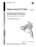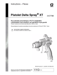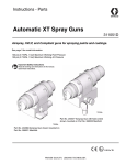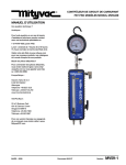
1
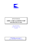
Instructions - Parts
Delta
®
Spray
XT Gun
310692D
For Airspray, HVLP, and Compliant guns with pressure, siphon, and
gravity feeds.
300 psi (2.1 MPa, 21bar) Maximum Working Fluid Pressure
100 psi (0.7 MPa, 7 bar) Maximum Working Air Pressure
Important Safety Instructions
Read warnings and instructions in this manual.
Save these instructions.
See page 4 for selection list of models.
ti4819
Graco Inc. P.O. Box 1441 Minneapolis, MN 55440-1441
Copyright 2004, Graco Inc. is registered to I.S. EN ISO 9001
II 2 G
Related Manuals
Contents
Related Manuals . . . . . . . . . . . . . . . . . . . . . . . . . . . 2
Manual Conventions . . . . . . . . . . . . . . . . . . . . . . . . 2
Warnings . . . . . . . . . . . . . . . . . . . . . . . . . . . . . . . . . 3
Selection Charts . . . . . . . . . . . . . . . . . . . . . . . . . . . 4
Gun Selection . . . . . . . . . . . . . . . . . . . . . . . . . . . . . 6
Air Caps . . . . . . . . . . . . . . . . . . . . . . . . . . . . . . . . . . 6
Nozzle, Needle, and Tip Selection . . . . . . . . . . . . . 7
Installation . . . . . . . . . . . . . . . . . . . . . . . . . . . . . . . . 8
Setup . . . . . . . . . . . . . . . . . . . . . . . . . . . . . . . . . . . . . 9
Operation . . . . . . . . . . . . . . . . . . . . . . . . . . . . . . . . 13
Daily Gun Maintenance . . . . . . . . . . . . . . . . . . . . . 14
Troubleshooting . . . . . . . . . . . . . . . . . . . . . . . . . . . 18
Service . . . . . . . . . . . . . . . . . . . . . . . . . . . . . . . . . . 19
Parts . . . . . . . . . . . . . . . . . . . . . . . . . . . . . . . . . . . . 26
Accessories . . . . . . . . . . . . . . . . . . . . . . . . . . . . . . 30
Technical Data . . . . . . . . . . . . . . . . . . . . . . . . . . . . 33
Graco Standard Warranty . . . . . . . . . . . . . . . . . . . 34
Graco Information . . . . . . . . . . . . . . . . . . . . . . . . . 34
Related Manuals
The Delta Spray XT manual is also available in the following languages. See chart below for specific language and
part number.
French
310779
Norwegian
310785
German
310780
Swedish
310786
Italian
310781
Dutch
310787
Spanish
310782
Japanese
310788
Finnish
310783
Korean
310789
Danish
310784
Chinese
310790
Manual Conventions
WARNING
WARNING indicates a potentially hazardous situation
which, if not avoided, could result in death or serious
injury.
Warnings included in instructions generally have a
symbol indicating the hazard. Follow the instructions
and read the hazard section on warning page 3 for
additional information.
2
CAUTION
CAUTION indicates a potentially hazardous situation
which, if not avoided, may result in property damage
or destruction of equipment.
Note
A note indicates additional helpful information.
310692D
Warnings
Warnings
The following warnings include general safety information for this equipment. More specific warnings are included in
the text where applicable.
WARNING
FIRE AND EXPLOSION HAZARD - FE CED/IND General
Flammable fumes, such as solvent and paint fumes, in work area can ignite or explode. To help prevent
fire and explosion:
• Use equipment only in well ventilated area.
• Eliminate all ignition sources; such as pilot lights, cigarettes, portable electric lamps, and plastic drop
cloths (potential static arc).
• Keep work area free of debris, including solvent, rags and gasoline.
• Do not plug or unplug power cords, or turn power or light switches on or off when flammable fumes
are present.
• Ground equipment and conductive objects in work area. See Grounding instructions.
• Use only grounded hoses.
• Hold gun firmly to side of grounded pail when triggering into pail.
• If there is static sparking or you feel a shock, stop operation immediately. Do not use equipment
until you identify and correct the problem.
PRESSURIZED EQUIPMENT HAZARD
Fluid from the gun/dispense valve, leaks, or ruptured components can splash in the eyes or on skin and
cause serious injury.
• Follow Pressure Relief Procedure in this manual, when you stop spraying and before cleaning,
checking, or servicing equipment.
• Tighten all fluid connections before operating the equipment.
• Check hoses, tubes, and couplings daily. Replace worn or damaged parts immediately.
EQUIPMENT MISUSE HAZARD
Misuse can cause death or serious injury.
• Do not exceed the maximum working pressure or temperature rating of the lowest rated system
component. See Technical Data in all equipment manuals.
• Use fluids and solvents that are compatible with equipment wetted parts. See Technical Data in all
equipment manuals. Read fluid and solvent manufacturer’s warnings.
• Check equipment daily. Repair or replace worn or damaged parts immediately.
• Do not alter or modify equipment.
• For professional use only.
• Use equipment only for its intended purpose. Call your Graco distributor for information.
• Route hoses and cables away from traffic areas, sharp edges, moving parts, and hot surfaces.
• Do not use hoses to pull equipment.
• Comply with all applicable safety regulations.
TOXIC FLUID OR FUMES HAZARD
Toxic fluids or fumes can cause serious injury or death if splashed in the eyes or on skin, inhaled, or
swallowed.
• Read MSDS’s to know the specific hazards of the fluids you are using.
• Store hazardous fluid in approved containers, and dispose of it according to applicable guidelines.
310692D
3
Selection Charts
Selection Charts
Pressure feed spray guns
Orifice Size
in. (mm)
HVLP
Compliant
Airspray
.030 (0.75)
234647
234693
234636
.042 (1.0)
234648
234694
234637
.055 (1.4)
234649
234695
234638
.070 (1.8)
234650
234696
234639
.086 (2.2)
234651
234640
.110 (2.8)
234652
234641
.042 (1.0)
234653*
234644*
.055 (1.4)
234654*
234645*
.070 (1.8)
234655*
234646*
.030 (0.75)
249856†
.042 (1.0)
249857†
.055 (1.4)
249858†
.070 (1.8)
249589†
* Guns included with hardened SST needle tips, and nozzles.
† Clear chromate gun body.
Pressure feed spray guns with 1 quart pressure feed cup 239802
Orifice Size
in. (mm)
HVLP
.042 (1.0)
234709
.055 (1.4)
234710
.070 (1.8)
234711
.086 (2.2)
234712
Siphon feed spray guns
4
Spray Gun with 1 quart
SST cup
Spray Gun Only
Orifice Size
in. (mm)
Compliant
Airspray
Compliant
Airspray
.055 (1.4)
234695
234642
234732
234718
.070 (1.8)
234696
234643
234733
234719
310692D
Selection Charts
Gravity feed spray guns (without gravity cup)
Orifice size
in. (mm)
HVLP
Compliant
Airspray
.055 (1.4)
234658
234685
234662
.070 (1.8)
234659
234686
234663
Gravity feed spray guns with 16 oz. gravity cup
Orifice size
in. (mm)
HVLP
Compliant
Airspray
.055 (1.4)
234713
234721
234705
.070 (1.8)
234714
234722
234706
Gravity feed spray guns with 3M™ PPS™ gravity cup
Orifice Size
in. (mm)
HVLP
Compliant
Airspray
.055 (1.4)
234681
234689
234677
.070 (1.8)
234682
234690
234678
310692D
5
Gun Selection
Gun Selection
HVLP Guns
Compliant Guns
An HVLP gun is a high transfer efficiency gun which limits the air pressure at the aircap to 10 psi maximum. In
some areas, an HVLP gun is required for compliance
with environmental standards.
A compliant gun is a high transfer efficiency gun which
has been tested to have a transfer efficiency greater
than or equal to HVLP guns. The Graco compliant guns
have no restrictions on aircap pressures, but the gun
inlet pressure must remain under 29 psi (21 MPa 2.1
bar) to remain in compliance.
Airspray Guns
Excellent atomization and high production rates typically
with some reduction in transfer efficiency.
Air Caps
The chart below lists the air caps available for pressure
feed, gravity, and siphon feed guns.
Spray Gun
Air Cap
ID
Typical Pattern
Width*
in. (mm)
Gun Feed
HVLP
321
15 (381)
HVLP
322
HVLP
Nozzle Orifice
in. (mm)
Part
Number
Pressure Feed
.030-.070
(.75-1.8)
234753
15 (381)
Pressure Feed
.086 (2.2)
234754
323
15 (381)
Pressure Feed
.110 (2.8)
234755
HVLP
320
12 (305)
Gravity/Siphon
Feed
.030-.070
(.75-1.8)
234752
Compliant
006
11 (279)
All Models
.030-.070
(.75-1.8)
234762
Airspray
315
13 (330)
Pressure Feed
.030-.070
(.75-1.8)
234757
Airspray
318
10 (254)
Pressure Feed
.086 (2.2)
234760
Airspray
319
10 (254)
Pressure Feed
.110 (2.8)
234761
Airspray
317
9 (229)
Gravity/Siphon
Feed
.030-.070
(.75-1.8)
234759
Airspray
313
10 (254)
Pressure Feed
.030-.070
(.75-1.8)
234756
Airspray
316
10 (254)
Pressure Feed
.030-.070
(.75-1.8)
234758
* Measured with gun nozzle 8 in. (203 mm) from target
surface.
6
310692D
Nozzle, Needle, and Tip Selection
Nozzle, Needle, and Tip Selection
The chart below lists the available nozzle sizes and
required fluid needle and nozzles for the Delta Spray XT
guns. The HVLP, Compliant, and Airspray guns all use
the same nozzle design and fluid needles. When spraying high flow rates and high viscosity materials use the
larger nozzle sizes and when spraying light materials or
low flow rates, use the smaller nozzle sizes.
Nozzle
Orifice
in.
(mm)
Nozzle
Fluid
Needle
Assy.
Needle
Tip
Needle/Nozzle
Kit
Typical
Uses
.030
(.75)
234741
234765
234777
234829
Light
Stains
.042
(1.0)
234742
234765
234777
234830
.051
(1.3)
234743
234767
234778
234831
.055
(1.4)
234744
234767
234778
234832
.059
(1.5)
234745
234767
234778
234833
.070
(1.8)
234746
234767
234778
234834
.086
(2.2)
234747
234769
234779
234835
.110
(2.8)
234748
234770
234780
234836
.042
(1.0)
234749
234766
234781*
234774
.055
(1.4)
234750
234768
234782*
234775
.070
(1.8)
234751
234768
234782*
234776
low flow
Low
Viscosity
Medium
Viscosity
High
ViscosityAdhesives
high flow
Nozzle
and
needle tip
made from
hardened
stainless
steel for
longer life
* Use with shut off spring 110402, see parts page 26.
310692D
7
Installation
Installation
Top and bottom feed guns
G
E
A
D
C
H
F
B*
ti4819
FIG. 1
Key:
A
B
C
D
8
Delta Spray XT Gun
Fluid Inlet, 3/8 npsm (R3/8-19)*
Air Inlet
Air Hose
recommended 5/16 in. (7.9 mm) ID hose
optional 3/8 in. (9.5 mm) ID hose
E
F
G
H
Air Shutoff Valve
Air Regulator
Air Filter
Air Supply Line
*Pressure and siphon feed guns will have bottom feed
insert. Gravity feed guns will have a top feed insert.
310692D
Setup
Setup
Flushing the gun
3. Install an air filter (G). See FIG. 1.
4. Use a 5/16 inch (7.9 mm) I.D. air hose to minimize
excessive pressure drop in the hose.
Flush the spray gun before putting any paint
through the gun.
5. Connect the air hose (D) to the 1/4 npsm gun air
inlet (C).
WARNING
Read warnings, page 3. Follow Top and bottom feed
guns installation, page 8.
C
1. To flush the gun, use a solvent that is compatible
with paint to be sprayed. Hold a metal part of the
gun firmly to a grounded metal pail. Trigger the gun
to flush solvent through gun.
D
ti4837a
FIG. 3
6. Connect the other end of the air hose (D) to a regulated air supply line.
D
ti4836a
FIG. 2
ti4838a
Connecting the air line
FIG. 4
2. Install an air pressure regulator (F). See FIG. 1.
310692D
9
Setup
Connecting the fluid hose
Connecting the fluid supply
(Pressure feed guns only)
For packages that include fluid cups, use the following
chart for installation instructions.
1. To control fluid pressure to the gun, install a fluid
regulator on the fluid line.
Cup attachment
Instruction Manual
3M PPS
310693
Gravity Cup
308792
Siphon Cup
308792
Pressure Cups
308791
2. Connect the fluid hose (J) to the gun fluid inlet (B)
3/8-18 npsm [R 3/8-19] compound thread.
B
J
Positioning the Air Cap
Rotate the air cap as needed to achieve the desired
spray pattern direction. To create a round pattern, turn
the pattern air off by turning the pattern adjustment knob
(25) fully clockwise. See FIG. 7.
ti4854a
FIG. 5
3. Connect the other end of the fluid hose (J) to a regulated fluid supply line.
ti4839a
FIG. 6
10
310692D
Setup
Adjusting the Spray Pattern
1. To achieve full fan pattern, open the pattern adjustment valve (25) by turning the knob fully counterclockwise.
3. To establish the correct fluid flow, turn the fluid
adjustment knob (21) counterclockwise until no
restriction of the trigger movement is felt, then turn
out another half turn. When the knob is turned far
enough, the trigger should be able to touch the gun
handle when the gun is triggered.
(Close)
(Open)
(Open)
(Close)
25
21
ti4841a
FIG. 7
ti4840a
FIG. 8
2. Trigger gun and adjust gun air pressure:
Gun Inlet Air
Pressure
Hose Inlet Air
Pressure
PSI (kpa, bar)
PSI (kPa, bar)
25 ft 5/16 in.
(7.9 mm) ID hose
HVLP Gravity
29 (210, 2.1)
50 (345, 3.4)
HVLP
Pressure
40 (280, 2.8)
72 (480, 4.8)
Compliant
29 (210, 2.1)
41 (280, 2.8)
Airspray
gravity feed
40 (280, 2.8)
52 (345, 3.4)
Airspray
pressure feed
40 (280, 2.8)
56 (410 4.1)
4. Pressure feed only: Adjust fluid pressure to achieve
desired fluid flow rate
5. To reduce fluid flow, turn the fluid adjustment knob
(21) clockwise.
•
•
(Open)
WARINING
PRESSURIZED EQUIPMENT HAZARD
To avoid injury, never open the fluid adjustment
knob (21) beyond the one half turn indicated in
step 3 in Adjusting the Spray Pattern. If the red
band on the knob stem (21) is visible, the knob is
not adjusted correctly and could result in serious
injury. Repeat step 3 in Adjusting the Spray
Pattern.
If the fluid adjustment knob is turned clockwise
all the way, the gun will emit only air.
If you cannot achieve the correct fluid flow with
the fluid adjustment knob, a different sized nozzle may be necessary. For smaller fluid flow,
use the next size smaller nozzle. For a larger
fluid flow, use the next size larger nozzle.
(Close)
21
ti4840a
FIG. 9
6. Spray a test pattern. Evaluate the spray pattern size
and atomization.
310692D
11
Setup
7. To achieve a narrow spray pattern, turn pattern
adjustment valve (25) clockwise.
9. To improve atomization, reduce the fluid flow rate.
Increasing the air pressure can improve atomization
but may result in poor Transfer Efficiency (TE) or
non-compliant operation.
•
(Close)
(Open)
•
25
•
ti4841a
FIG. 10
8. For HVLP only: To measure the aircap atomizing
pressures, use the accessory aircap verification kit.
See Accessories on page 30.
12
•
For gravity feed HVLP guns, at 29 psi (200 kPa,
2.0 bar) gun inlet air pressure, the pressure at
the aircap will be 10 psi (70 kpa, 0.7 bar).
For pressre feed HVLP guns, at 40 psi (280
kPa, 2.8 bar) gun inlet air pressure, the pressure at the air cap will be approximately 10 psi
(70 kpa, 0.7 bar).
For HVLP guns, local laws may limit the maximum automatic air pressure to 10 psi (70 kPa,
0.7 bar) at the air cap for HVLP compliance.
The accessory Air Cap Verification Kit is available to measure the atomizing pressure at the
air cap. See Accessories on page 30.
For Compliant guns, to maintain compliant
operation (TE equal to HVLP) the gun inlet
pressure must not exceed 29 psi.
310692D
Operation
Operation
Pressure Relief Procedure
1. To achieve the best results when applying fluid:
•
WARNING
•
Keep the gun perpendicular and 6 to 8 inches
(150 to 200 mm) from the object being sprayed.
Use smooth, parallel strokes across the surface
to be sprayed with 50% overlap.
Incorrect
Follow Pressure Relief Procedure, page 13 when
you stop spraying and before cleaning, checking, servicing, or transporting equipment. Read warnings,
page 3.
1. Turn off air and fluid supply.
2. Hold a metal part of the gun firmly to a grounded
metal pail. Trigger the gun to relieve pressure.
ti4843a
Correct
ti4836a
FIG. 11
Applying the Fluid
When using the HVLP spray gun, instead of a conventional airspray gun, you may need to use a slightly
slower hand movement and make fewer passes with the
gun to coat a part. This is due to the reduced spray
velocity produced by lower HVLP air pressures, along
with a larger fluid particle size because there is less air
to blow off solvents than what is produced by conventional airspray. Take care to avoid runs or sags as you
spray.
310692D
ti4842a
FIG. 12
13
Daily Gun Maintenance
Daily Gun Maintenance
WARNING
Follow Pressure Relief Procedure, page 13 when
you stop spraying and before cleaning, checking, servicing, or transporting equipment. Read warnings,
page 3.
CAUTION
Methylene chloride with formic or propionic acid is not
recommended as a flushing or cleaning solvent with
this gun as it will damage aluminum and nylon components.
CAUTION
Solvent left in gun air passages could result in a poor quality paint finish. Do not use any cleaning method which
may allow solvent into the gun air passages.
Do not point the gun up while cleaning it.
Do not wipe the gun with a cloth soaked in solvent;
ring out the excess.
Do not immerse the gun in solvent.
Do not use metal tools to clean the air cap holes as
this may scratch them; scratches can distort the
spray pattern.
General maintenance
✓
Relieve the pressure.
✓
Clean the fluid and air line filters daily.
14
✓
Check for any fluid leakage from the gun and fluid
hoses.
✓
Flush the gun before changing colors and whenever
you are done operating the gun.
310692D
Daily Gun Maintenance
Flushing and cleaning
3. Connect the solvent supply hose to the gun.
Gravity and Siphon Feed Guns
1. For packages that include fluid cups, use the following chart for flushing and cleaning instructions.
Cup attachment
Instruction Manual
3M™ PPS™
310693
Gravity Cup
308792
Siphon Cup
308792
Pressure Cups
308791
2. Continue to step 8 to perform daily cleaning of the
Delta Spray XT gun.
ti4854a
FIG. 14
4. Hold metal part of gun against a grounded metal
container, trigger, and flush the gun with solvent
until all traces of paint are removed from the gun
passages.
Pressure Feed Guns
WARNING
Follow Pressure Relief Procedure, page 13 when
you stop spraying and before cleaning, checking, servicing, or transporting equipment. Read warnings,
page 3.
ti4836a
1. Relieve the pressure, page 13.
FIG. 15
2. Disconnect the fluid supply hose and air supply
hose from the gun.
5. Turn off the solvent supply.
6. Relieve the pressure.
7. Disconnect the solvent supply hose from the gun.
ti4944a
ti4944a
FIG. 16
ti4945a
FIG. 13
310692D
15
Daily Gun Maintenance
8. Remove the air cap retaining ring assembly (15)
and air cap (14).
12. Scrub the air cap retaining ring, air cap, and fluid
nozzle with the soft-bristle brush.
9. Trigger the gun while you remove the fluid nozzle
(12) from the gun with the gun tool (28)
14, 15
12
28
ti4847a
FIG. 20
ti4844b
FIG. 17
•
CAUTION
Trigger the gun whenever you tighten or remove the
nozzle. This keeps the needle seat away from the
nozzle seating surface and prevents the seat from
being damaged.
10. Dip the end of a soft-bristle brush into a compatible
solvent. Do not continuously soak the brush's bristles with solvent and do not use a wire brush.
•
•
To clean out air cap holes, use a soft implement, such as a toothpick, to avoid damaging
critical surfaces.
Clean the air cap and fluid nozzle daily, minimum. Some applications require more frequent
cleaning.
Do not soak the air cap retaining ring in solvent
for prolonged periods of time.
13. Trigger the gun while you install the fluid nozzle (12)
with the gun tool (28). Tighten the nozzle securely to
40 in-lb (4.5 N•m) to obtain a good seal.
28
14,
15
ti4845a
12
FIG. 18
ti4844b
FIG. 21
11. With the gun pointed down, clean the front of the
gun, using the soft-bristle brush and solvent.
14. Install the air cap retaining ring assembly (15) and
air cap (14).
ti4846a
FIG. 19
16
310692D
Daily Gun Maintenance
15. Dampen a soft cloth with solvent and wring-out the
excess. Point the gun down and wipe off the outside
of the gun.
16. After cleaning the gun, lubricate the following parts
with lubricant 111265 daily:
•
•
•
Fluid adjustment knob threads
Trigger pivot pin
Fluid needle shaft
Lubricate
ti4848a
FIG. 22
Lubricate
ti4819a
FIG. 23
310692D
17
Troubleshooting
Troubleshooting
WARNING
Follow Pressure Relief Procedure, page 13 when
you stop spraying and before cleaning, checking, servicing, or transporting equipment. Read warnings,
page 3.
Problem
Cause
Fluid flow is fluttering while spraying. 1. Fluid nozzle not tight enough.
Solution
1. Tighten fluid nozzle to 40 in-lb
(4.5 N•m).
2. Fluid filter clogged.
2. Check fluid filter.
3. Fluid source empty.
3. Refill
Fluid flow fades while spraying high
viscosity fluids.
1. Air hose size is too restricted for
higher air flow being used.
1. Use 5/16 in. (7.9 mm) I.D. air
hose if the hose is 25 ft. (7.6 m)
long. If longer hose is needed,
use a 3/8 in. (9.5 mm) I.D. hose.
Pattern becomes off-set or heavy on
ends.
1. Air cap horn holes plugged or
damaged.
1. Clean air cap horn holes with
non-metallic item such as a
toothpick, or replace air cap.
2. Nozzle tip dirty or damaged.
2. Clean or replace nozzle.
Gun fluid pressure is too high with
gun triggered (cannot achieve
desired flow rate).
Using needle/nozzle kit with too small Use needle/nozzle kit with larger oriorifice.
fice.
Using a low fluid pressure setting, the Using needle/nozzle kit with too large Use needle/nozzle kit with smaller
orifice.
fluid flow is too high, making it neces- orifice.
sary to restrict needle travel to
reduce fluid flow.
Fluid system will not operate at low
enough fluid pressure [below 10 psi
(70 kPa, 0.7 bar)].
18
There is no fluid regulator, or air reg- Add low pressure fluid regulator, or
ulator or pressure pot is not sensitive add more sensitive low pressure air
enough at low pressures.
regulator on pressure pot.
310692D
Service
Service
Replacing the air and fluid
packings
2. Flush the spray gun, page 9.
3. Remove the air cap retaining ring (15A), seal (15B),
and air cap (14).
Tools needed:
•
Gun Tool - provided
•
Packing Installation Tool - provided
•
Adjustable Wrench
•
Screw Driver
•
Lubricant part no. 111265; see Accessories, page
28, to order
•
Compatible Solvent
15A 15B
28
12
14
ti4849b
•
•
•
Order Repair Kit 234828. See Parts starting on
page 25.
Clean parts with a solvent that is compatible
with the parts and the fluid being sprayed.
FIG. 24
4. Trigger the gun while you remove the fluid nozzle
(12) with the gun tool (28). See FIG. 24.
5. Remove the screw (11), pin (17), wave washer (18),
and trigger (10).
Lightly lubricate the parts indicated with lubricant 111265.
17
Disassembling the gun
18
WARNING
Follow Pressure Relief Procedure, page 13 when
you stop spraying and before cleaning, checking, servicing, or transporting equipment. Read warnings,
page 3.
11
10
1. Relieve the pressure, page 13.
ti4828a
FIG. 25
310692D
19
Service
6. Loosen the hex nut (9) with the gun tool (28).
Replacing the spray housing o-rings and
packings
1. With the spray housing (2A) removed from the insert
(4), use a mechanical pick to remove the o-ring (2B)
from the housing (2A).
9
2A
36
4
2B
ti4978a
FIG. 26
7. Remove the spray housing (2A) and insert (4).
ti4829b
FIG. 28
2A
4
2. Remove o-ring (34) from the insert (4).
O-ring (2B) is slightly larger than o-ring (34).
3. Install a new o-ring (34) into the insert (4). Install a
new o-ring (2B) into the housing (2A).
NOTE: To ease o-ring installation, place the insert
(4) into the spray housing (2B) to plug the end.
Install one end of the o-ring into the groove in the
housing, then press the rest of the o-ring into place.
ti4830b
FIG. 27
20
310692D
Service
4. Unscrew the packing screw (8) from the insert (4)
with the gun tool (28).
1. Unscrew the pattern adjustment valve assembly (25
A-D).
7
6
5
Replacing the pattern adjustment valve
packings
4
25B
25A
25C
25D
8
ti4834a
FIG. 29
ti4857a
5. Using a mechanical pick, push the three fluid packings (5, 6, 7) out of the insert (4). Be careful not to
damage the insert. Discard the old fluid packings.
6. Place the new fluid packings (5, 6, 7) and packing
screw (8) onto the needle (13). Note the orientation
of the parts.
5
6
7
8
FIG. 31
2. Using a needle nose pliers, remove the retaining
ring (25D) and unscrew the pattern adjustment
valve (25C).
3. Using a mechanical pick, remove the u-cup packings (25B) from the pattern adjustment nut (25A).
Be careful not to damage the seal surface or the
nut's internal threads.
13
4. One at a time, install the new u-cup packings (25B)
with the packing installation tool (29); the u-cup lips
must face toward the tool.
4
29
25A
25B
ti4834a
FIG. 32
FIG. 30
7. Insert the fluid needle (13) into the back of the insert
(4) to install the fluid packings (5).
8. Tighten the packing screw (8) just enough to hold
the packings (5) in the insert (4). The needle (13)
must move freely. Remove the needle.
310692D
5. Push each u-cup packing (25B) into the pattern
adjustment nut (25A) until a definite snap is felt.
6. Lubricate the pattern adjustment valve (25C)
threads and install the valve into the nut (25A).
Install the retaining ring (25D), then back out the
pattern adjustment valve as far as the retaining ring
allows it to go.
21
Service
Replacing the fluid valve packings
1. Remove the fluid adjustment knob (21) and fluid
spring (23).
4. Place the new u-cup packing (16) on the packing
installation tool (29), with the u-cup lips facing the
tool as shown.
2. Pull the fluid needle (13) out the back of the gun.
16
26
13
21
16
29
ti4851a
FIG. 34
5. Push the packing (16) into the back of the gun until
a definite snap is felt.
23
22
37
20
19
ti4850a
FIG. 33
3. Remove the fluid valve nut (19), air valve spring
(22), and air valve assembly (26). Discard the air
valve assembly. Using a mechanical pick, remove
the u-cup packing (16) from the gun body.
6. Using a mechanical pick, remove the u-cup packing
(20) and spacer (37) from the fluid valve nut (19). Be
careful not to damage the seal surface or the nut's
internal threads.
7. Using the packing installation tool (29), install the
new u-cup packings (20) into the fluid valve nut (19).
The u-cup lips must face toward the tool as shown.
This will help apply even pressure to the u-cup lips
and avoid damaging them.
19
20
ti4852a
FIG. 35
8. Push the u-cup packings (20) into the fluid valve nut
(19) until a definite snap is felt.
22
310692D
Service
Reassembling the gun
sary. If replacing needle tip, use low strength thread
adhesive on needle tip threads.
To ensure proper alignment of the parts, assemble
parts in the exact order given in the following steps.
1. Slide the insert (4) into the spray housing (2A), and
install them onto the gun body (1). Align the housing
with the slot and lip (A) on the gun body.
2A
4
4. Lubricate the outside of the new air valve assembly
(26) and place it on the fluid needle (13), against the
nut (B). See FIG. 38.
5. Install the fluid needle (13) and the air valve assembly (26) into the back of the gun.
A
13
26
B
ti4853a
FIG. 38
ti4830a
FIG. 36
2. Tighten the hex nut (9) onto the insert (4) hand-tight,
then loosen the nut about one turn so the insert (4)
and spray housing sit loosely in the gun body.
6. With u-cup (20) and spacer (37) already installed
into fluid nut (19), point gun down and install spring
(22) and fluid nut (19). Tighten the fluid nut (19) to
125-135 in-lb (14-15 N•m).
21
9
23
ti4978a
FIG. 37
3. Check the fluid needle (13) for damage or excessive
wear. Replace needle tip or entire needle if neces-
310692D
22
37
20
19
ti4850a
FIG. 39
7. Install needle spring (23). Install fluid adjustment
knob (21).
23
Service
8. Install the trigger (10), pivot pin (17), wave washer
(18), and screw (11). Torque the screw to 20-30 in-lb
(2.3-3.4 N•m).
12. Install the pattern adjustment valve assembly
(25A-D). Torque the nut (25A) to 125-135 in-lb
(14-15 N•m).
17
18
25A-D
ti4832a
11
10
ti4828a
FIG. 40
9. Apply a thin film of lubricant to the fluid nozzle seat
and threads.
10. Trigger the gun while you install the fluid nozzle (12)
with the gun tool (28). Torque the nozzle securely to
40 in-lb (4.5 N•m).
28
12
FIG. 42
13. Tighten the packing screw (8) by turning the screw
in until it touches the fluid packings, then tighten one
full turn to pre-set the packings. Loosen the screw,
then turn it in until it touches the packings again.
Tighten the screw 1/12 turn more (equal to half the
distance between points on the hex head). See FIG.
41.
14. Trigger the gun to test the needle movement. If the
needle does not return after the trigger is released
or is slow in returning, loosen the packing screw (8)
until the needle returns freely.
15. Replace seal (15B). Install the air cap (14), air cap
retaining ring (15A), and seal (15B). Hand-tighten
the ring.
8
14
15A
15B
9
ti4849i
FIG. 41
ti4980a
11. Tighten the hex nut (9) securely to 125-135 in-lb
(14-15 N•m).
FIG. 43
16. Make sure the gun fluid packings are sealing properly by spraying solvent at low pressure before fully
pressurizing the gun with the fluid to be sprayed.
17. If the fluid packings leak, tighten the packing screw
(8) slightly and retest until the packings and fluid
needle seal completely.
24
310692D
Service
310692D
25
Parts
Parts
Airspray, HVLP, and Compliant Guns
With Pressure, Gravity, and Siphon Feeds
25D 25B*
15A
15B*
14
12
17
25C
25A
1
13
16*
7*
26*
13A
8
6*
5*
35
23
22
37* 20* 19
21
9
2B*
2A
36*
4†
24
11
ti4821a
29
10
28
ti4831b
26
† Insert (4) appears for top or
bottom feed depending on application.
310692D
Parts
Airspray, HVLP, and Compliant Guns
With Pressure, Gravity, and Siphon Feed
Ref.
No
1
2
Part No. Description
Qty.
234740 BODY, gun
1
SPRAY HOUSING ASSY., includes
1
items 2A-B; For part number, see
chart below
2A
HOUSING, spray;
1
2B*
O-RING
1
4
15D661 INSERT, fluid; pressure and siphon
1
feed guns only
15C463 INSERT, fluid; gravity feed guns
1
only
5*
188494 PACKING, spreader
1
6*
188495 PACKING, u-cup
1
7*
192351 PACKING, spacer
1
8
192352 SCREW, packing
1
9
192348 NUT, hex; 1/2 - 20 UNF
1
10
15D993 TRIGGER
1
11
203953 SCREW, trigger lock
1
12★
NOZZLE, fluid;
1
13★
NEEDLE ASSY.; includes item 13A
1
13A★
TIP, needle
1
14★
AIR CAP
1
15
239953 RETAINING RING ASSY., includes
1
items 15A-B
15A
RING
1
15B*
SEAL
1
16*
188493 U-CUP
1
17
192272 PIN, pivot
1
19
15C468 NUT, fluid valve
1
20*
110453 U-CUP
1
21
15E245 KNOB, fluid adjustment
1
22
114069 SPRING, air valve
1
23
114072 SPRING, needle
1
110402 SPRING, needle; for SST needle
1
tips
24
195065 INLET, air;
1
15C518 INLET, air;
1
HVLP gravity feed guns only
310692D
Ref.
No
25
Part No. Description
Qty.
234379 VALVE ASSY., pattern adjustment;
1
includes items 25A-D; airspray
guns only
234297 VALVE ASSY., pattern adjustment;
1
includes items 25A-D; compliant
and HVLP guns only
25A 15C468 NUT, pattern adjustment
1
25B* 110453 U-CUP
2
25C 15C877 VALVE; Airspray gun
1
15C469 VALVE; HVLP and Compliant guns
25D 114068 RING, retaining
1
26*
234363 AIR VALVE ASSY.
1
28
15E581 TOOL, gun
1
29
192282 TOOL, seal installation
1
35
15C480 WAVE WASHER
1
36*
113137 O-RING
1
37*
15E246 SPACER
1
★ See chart on pages 6 and 7 for part number.
*
Parts included in Kit 234828 (purchase separately).
Gun
Spray Housing
Assembly
HVLP Gravity Feed
234632
HVLP Pressure Feed
234591
Compliant Pressure/Siphon Feed
234635
Compliant Gravity Feed
234634
Airspray Pressure/Siphon Feed
234592
Airspray Gravity Feed
234633
27
Parts
234788 Spatter or Specking Airspray Gun
25
15A
15B*
1
17
14 37 12
13
16*
26*
8
7*
6*
5*
35
23
22
20* 19
21
9
2B*
2A
36*
4
24
11
ti3652482aa
29
10
28
ti4831b
28
310692D
Parts
234788 Spatter or Specking Airspray Gun
Ref.
No
1
2
Part No. Description
Qty.
234740 BODY, gun
1
234592 SPRAY HOUSING ASSY., includes
1
items 2A-B;
2A
HOUSING, spray;
1
2B*
O-RING
1
4
15D661 INSERT, fluid;
1
5*
188494 PACKING, spreader
1
6*
188495 PACKING, u-cup
1
7*
192351 PACKING, spacer
1
8
192352 SCREW, packing
1
9
192348 NUT, hex; 1/2 - 20 UNF
1
10
15D993 TRIGGER
1
11
203953 SCREW, trigger lock
1
12
15E139 NOZZLE, fluid
1
13
239644 NEEDLE ASSY.
1
14
196109 AIR CAP
1
15
239953 RETAINING RING ASSY., includes
1
items 15A-B
15A
RING
1
15B*
SEAL
1
310692D
Ref.
No
16*
17
19
20*
21
22
23
24
25
26*
28
29
35
36*
37
*
Part No.
188493
192272
15C468
110453
15E245
114069
114072
195065
15E138
234363
15E581
192282
15C480
113137
196111
Description
U-CUP
PIN, pivot
NUT, fluid valve
U-CUP
KNOB, fluid adjustment
SPRING, air valve
SPRING, needle
INLET, air
CAP
AIR VALVE ASSY.
TOOL, gun
TOOL, seal installation
WAVE WASHER
O-RING
BAFFLE
Qty.
1
1
1
2
1
1
1
1
1
1
1
1
1
1
1
Parts included in Kit 234828 (purchase separately).
29
Accessories
Accessories
Cleaning Brush 105749
Air Control Valve 234784
For use in cleaning gun
Comes with gauge. Allows
for air pressure adjust-
ment at gun inlet.
Lubricant 111265
One 4 oz. (113 gram) tube sanitary (non-silicone) lubricant for fluid seals and wear areas.
Air Control Valve Kit 243670
Install on the gun air inlet to control both the atomizing
air and the pressure in the spray gun cup (if used).
1/4 npsm x 1/4-19 BSPT.
HVLP Air Pressure Verification
Kit
For use in checking HVLP air cap atomizing air pressure
at various supply air pressures. Not to be used for actual
spraying.
Install the kit air cap on the gun. Turn on the air to the
gun, then trigger the gun and read the atomizing air
pressure on the gauge.
30
310692D
Accessories
Gun Air Regulator Assy. 235119
0-100 psi (0-0.7 MPa, 0-7 bar) air regulator to control air
pressure to gun.
Installing the gun air regulator adds a pressure
drop that could limit the air cap pressure.
Gravity Cup Holder Bracket
192407
Fits both gravity cup sizes.
SST Pressure Cup Kit 239802
with single air regulator
1 qt. (0.95 liter) capacity, 304 stainless steel cup.
Includes a pressure relief valve and a single air regulator and gauge.
Gravity Cup
For use with gravity feed gun. Nylon cup, 304 stainless
steel 3/8 npsm(f) fluid inlet fitting, fluid filter cartridge
included.
Part Number
Size
239714
16 oz. (474 cc)
239715
8 oz. (237 cc)
1 Quart Remote SST Pressure
Cup 239804
1 qt. (0.95 liter) capacity, 304 stainless steel cup.
Includes air pressure regulator and gauge, 4 ft. (1.2 m)
length air and fluid hose with 1/4 npsm(f) swivel ends,
pressure relief valve, and rigid hook handle.
310692D
31
Accessories
SST Pressure Cup Kit 239803
with double air regulator
1 qt. (0.95 liter) capacity, 304 stainless steel cup.
Includes a pressure relief valve, a 0-100 psi (0-0.7 MPa,
0-7 bar) air regulator for gun atomization, and a 0-15 psi
(0-104 kPa, 0-1.0 bar) air regulator for the 1 qt. pressure
cup supply air.
Installing the pressure cup kit adds a pressure
drop that could limit the air cap pressure.
3M™ PPS™ Paint Preparation
System
Gravity Feed 234837
Siphon Feed 234773
For use with gravity feed gun.Includes PPS cup, liner,
and adapter. See instruction manual 310693 for more
information.
Gravity Feed
Disposable Polythylene Cup
Liners
Paint and solvent resistant. 40 Liners per box.
Siphon Feed
Fluid Shut Off Spring 110402
Replaces standard spring 114072 when using SST needle tips, and provides increased shut off force in difficult
applications.
112490 - 1 Quart Size
112491 - 2 Quart Size
32
310692D
Technical Data
Technical Data
Category
Maximum Working Fluid Pressure
Maximum Working Air Pressure
Maximum Compliant Inbound Air Pressure
HVLP Gravity/Siphon Feeds
HVLP Pressure Feed
Fluid and Air Operating Temperature Range
Weight
Air Inlet
Fluid Inlet
Wetted Parts
Noise Data*
Sound Pressure
Sound Power
Air Consumption Gravity/Siphon Feed:
Airspray at 50 psi inlet
HVLP at 29 psi inlet
Compliant at 29 psi inlet
Air Consumption Pressure Feed:
Airspray at 40 psi inlet
HVLP at 40 psi inlet
Compliant at 29 psi inlet
Data
300 psi (2.1 MPa, 21 bar)
100 psi (0.7 MPa, 7 bar)
29 psi (200 kPa, 2.0 bar)
29 psi (200 kPa, 2.0 bar)
40 psi (280 kPa, 2.8 bar)
32°F to 109°F (0°C to 43°C)
22.3 oz. (632 g)
1/4-18 npsm
3/8 npsm
304, 303,17-4 PH Stainless Steel, PEEK, Acetal, Ultra
High Molecular Weight Polyethylene
84.4 Db(A)
94.0 Db(A)
14.1 scfm
15.5 scfm
11.2 scfm
12.5 scfm
21.0 scfm
11.2 scfm
*All readings were taken with the gun controls fully open and with 40 psi (280 kPa, 2.8 bar). Sound pressure was
tested to CAGI-PNUEROP-1969. Sound power was tested to ISO 3744-1981.
310692D
33
Graco Standard Warranty
Graco warrants all equipment referenced in this document which is manufactured by Graco and bearing its name to be free from defects in material
and workmanship on the date of sale to the original purchaser for use. With the exception of any special, extended, or limited warranty published by
Graco, Graco will, for a period of twelve months from the date of sale, repair or replace any part of the equipment determined by Graco to be
defective. This warranty applies only when the equipment is installed, operated and maintained in accordance with Graco’s written
recommendations.
This warranty does not cover, and Graco shall not be liable for general wear and tear, or any malfunction, damage or wear caused by faulty
installation, misapplication, abrasion, corrosion, inadequate or improper maintenance, negligence, accident, tampering, or substitution of
non-Graco component parts. Nor shall Graco be liable for malfunction, damage or wear caused by the incompatibility of Graco equipment with
structures, accessories, equipment or materials not supplied by Graco, or the improper design, manufacture, installation, operation or maintenance
of structures, accessories, equipment or materials not supplied by Graco.
This warranty is conditioned upon the prepaid return of the equipment claimed to be defective to an authorized Graco distributor for verification of
the claimed defect. If the claimed defect is verified, Graco will repair or replace free of charge any defective parts. The equipment will be returned
to the original purchaser transportation prepaid. If inspection of the equipment does not disclose any defect in material or workmanship, repairs will
be made at a reasonable charge, which charges may include the costs of parts, labor, and transportation.
THIS WARRANTY IS EXCLUSIVE, AND IS IN LIEU OF ANY OTHER WARRANTIES, EXPRESS OR IMPLIED, INCLUDING BUT NOT LIMITED
TO WARRANTY OF MERCHANTABILITY OR WARRANTY OF FITNESS FOR A PARTICULAR PURPOSE.
Graco’s sole obligation and buyer’s sole remedy for any breach of warranty shall be as set forth above. The buyer agrees that no other remedy
(including, but not limited to, incidental or consequential damages for lost profits, lost sales, injury to person or property, or any other incidental or
consequential loss) shall be available. Any action for breach of warranty must be brought within two (2) years of the date of sale.
GRACO MAKES NO WARRANTY, AND DISCLAIMS ALL IMPLIED WARRANTIES OF MERCHANTABILITY AND FITNESS FOR A
PARTICULAR PURPOSE, IN CONNECTION WITH ACCESSORIES, EQUIPMENT, MATERIALS OR COMPONENTS SOLD BUT NOT
MANUFACTURED BY GRACO. These items sold, but not manufactured by Graco (such as electric motors, switches, hose, etc.), are subject to
the warranty, if any, of their manufacturer. Graco will provide purchaser with reasonable assistance in making any claim for breach of these
warranties.
In no event will Graco be liable for indirect, incidental, special or consequential damages resulting from Graco supplying equipment hereunder, or
the furnishing, performance, or use of any products or other goods sold hereto, whether due to a breach of contract, breach of warranty, the
negligence of Graco, or otherwise.
FOR GRACO CANADA CUSTOMERS
The Parties acknowledge that they have required that the present document, as well as all documents, notices and legal proceedings entered into,
given or instituted pursuant hereto or relating directly or indirectly hereto, be drawn up in English. Les parties reconnaissent avoir convenu que la
rédaction du présente document sera en Anglais, ainsi que tous documents, avis et procédures judiciaires exécutés, donnés ou intentés, à la suite
de ou en rapport, directement ou indirectement, avec les procédures concernées.
Graco Information
TO PLACE AN ORDER, contact your Graco distributor or call to identify the nearest distributor.
Phone: 612-623-6921 or Toll Free: 1-800-328-0211, Fax: 612-378-3505
All written and visual data contained in this document reflects the latest product information available at the time of publication.
Graco reserves the right to make changes at any time without notice.
MM 310692
Sales Office: Minneapolis
International Offices: Belgium, China, Japan, Korea
GRACO INC. P.O. BOX 1441 MINNEAPOLIS, MN 55440-1441
www.graco.com
Printed in USA 310692D
8/2005