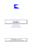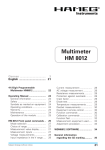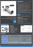
1
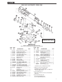
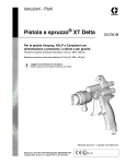
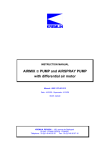
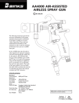
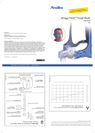
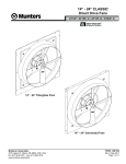
Mag HVLP Automatic AIRSpray Gun II 2 G X The following instructions provide the necessary information for the proper operation and preventive maintenance of the Binks MAG HVLP Manifold Mounted Airspray Gun. Please read and understand all information in this document in order to get the maximum performance from your new MAG HVLP airspray gun. Specifications: The automatic MAG HVLP gun is a conventional style airspray gun with special nozzle and modifications that allow it to operate at high transfer efficiencies in compliance with the “California South Coast Air Quality Management District” regulations as a “high volume, low pressure” airspray gun. Gun Body:Stainless Steel, Aluminum High pressure, low volume airflow is converted to high volume, low pressure within the gun body. Special air and fluid nozzle enable the gun to atomize fluid at low air pressure and velocities, creating the “soft spray” effect for high transfer efficiencies. ! Caution Before removing any components from spray gun, shut off air and material pressure. NOTE IMPORTANT REGULATORY NOTE regarding the use of this product appears on page 6. If you have any questions or do not understand the information presented, call your nearest service representative. Max. Air Pressure:100 psi/6.8 bar For HVLP compliance:See page 5 Max. Fluid Pressure:120 psi/8.3 bar Min./Max. Cylinder 50 psi/3.4 bar (min.), Actuating Pressure: 100 psi/6.8 bar (max.) Fluid Path:Stainless Steel Fluid Inlet and Outlet Size:1/4" NPT(F) thread Air Inlet Size:Atomizing Air: 1/4" NPT(F) manifold body, 1/4" NPT x 1/4" NPS(M) fitting (loose) Fan Air: 1/4" NPT(F) manifold body, 1/4" soc head plug (M) fitting (loose) Cylinder Air: 1/8" NPT(F) manifold body, 1/8" NPT x 1/4" O.D. tube fitting (loose) Gun Weight with Manifold:2.8 lbs. (1.27 kg) Gun Mounting Hole: 1/2" Dia. The MAG HVLP is approved to ATEX level II 2 G X and is suitable for use in Zones 1 and 2. CA PROP 65 PROP 65 WARNING WARNING: This product contains chemicals known to the State of California to cause cancer and birth defects or other reproductive harm. Replaces Part Sheet 77-2803R-10 Part Sheet 77-2803R-11 ! Warning High Pressure Can cause serious injury if equipment is installed or used incorrectly— Read, Understand, and observe all Warnings and Instructions in this Manual. Operate equipment only after all instructions are clearly understood. Flammable, Explosive and Toxic Vapors In this part sheet, the words WARNING, CAUTION and NOTE are used to emphasize important safety information as follows: ! WARNING Hazards or unsafe practices which could result in severe personal injury, death or substantial property damage. Toxic fluid Hazard • Know the specific hazards of the fluid you are using. This information is on the MSDS for the material being used. Read all fluid manufacturer warnings. • Store hazardous fluids in approved containers only. Dispose of all hazardous fluids in accordance with all state, local and national guidelines. • Wear the appropriate protective clothing, gloves, eyewear and respirator. Equipment misuse can cause the equipment to fail, malfunction, or start unexpectedly and result in serious injury. FIRE AND EXPLOSION HAZARD • Ground the equipment and object being sprayed. • Provide fresh air ventilation to avoid the build up of flammable fumes from the material being sprayed or from solvent. • Extinguish all open flames or pilot lights in spray area. • Electrically disconnect all equipment in the spray area. ! Caution Hazards or unsafe practices which could result in minor personal injury, product or property damage. •K eep the spray area free from all debris, including solvent rags. • If there is any static sparking while using the equipment, STOP SPRAYING IMMEDIATELY. Identify and correct the problem. EQUIPMENT MISUSE HAZARD • This equipment is for professional use only. •R ead and understand all instructional manuals, tags, and labels before operating equipment. •U se the equipment only for its intended purpose. If you are unsure about its purpose call your local Binks distributor. • Do not alter or modify this equipment. Use only genuine Binks parts. • Do not exceed the maximum working pressure of the lowest rated system component. THE MAXIMUM RATING OF THE MAG HVLP GUN IS 120 P.S.I. DO NOT EXCEED THE FLUID PRESSURE RATING. •R oute all hoses away from all sharp edges, moving parts, hot surfaces and high traffic areas. NOTE Important installation, operation or maintenance information. • Do not use hoses to pull the equipment. • Use only Binks approved hoses. •U se only solvents compatible with hoses and wetted parts of the equipment used. • Comply with all applicable local, state and national fire, electrical and other safety regulations. • Improper grounding, poor air ventilation, open flame or sparks can cause a hazardous condition and result in fire or explosion and cause serious injury. NOISE LEVELS • The A-weighted sound level of spray guns may exceed 85 dB(A) depending on the setup being used. It is recommended that ear protection is worn at all times when spraying. PROP 65 WARNING •W ARNING: This product contains chemicals known to the State of California to cause cancer and birth defects or other reproductive harm. The automatic Spray Gun models listed in the following declaration of conformity may be used in some potentially explosive atmospheres ONLY when the special conditions for safe installation and operation have been followed as expressed in this user manual (Part Sheet). These models are approved to ATEX regulations 94/9/EC, protection level: II 2 G X: Suitable for use in Zones 1 and 2. EC Declaration of Conformity Manuf. By:Finishing Brands 195 Internationale Blvd. Glendale Heights, IL 60139 Type/Series: Manifold Mounted Automatic Spray Guns Model: MAG HVLP: 4006-, 4007-, 4008-, 4009The equipment to which this document relates is in conformance with the following standards or other normative references: EN ISO 12100-1&2:2003 and BS EN 1953:1999 and thereby conform to the protection requirements of Council Directive 98/37/ EC relating to Machinery Safety Directive, and; EN 13463-1:2001, Council Directive 94/9/EC relating to Equipment and Protective Systems for use in Potentially Explosive Atmospheres, protection level II 2 G X. April 17. 2006 Approved By: ______________________________ Date:_____________ Chuck McCulloch, Finishing Brands Finishing Brands reserves the right to modify equipment specification without prior notice. 2 MAG HVLP AUTOMATIC Spray Gun Set-Up INSTRUCTIONS — SPRAY INSTRUCTIONS TO CHANGE FROM COMBINED FAN AND AIR TO SEPARATE FAN AND ATOMIZING AIR. 1.Remove item (31) side port control by turning counter-clockwise with a 9/16 wrench. 2.Install item (37) allen head set screw into thread at the bottom of tapered cavity of where the side port was. 3.Install item (38) side port plug into the upper part of the threaded cavity of where the side port was. 4.Remove item (34) 1/4 NPT plug from the fan air port and replace it with item (35) D.M. nipple. NOTE When fan and atomizing air is separated, they both activate “ON” and “OFF” with cylinder air control. SET UP FOR SPRAYING Safe connection. • Verify that the gun is grounded per the automated machine manufacturer’s recommendations. Connect fluid hose to the manifold. • Use 3/8" diameter material hose. • Fluid fitting from hose assembly to 1/4" NPT(f) fluid inlet on manifold is not furnished. • 1/4" diameter hose is recommended for low viscosity materials. Connect atomizing air to the manifold. • Install 1/4 NPS(m) x 1/4 NPT(m) fitting (furnished loose) in atomizing air port. • Use 5/16” diameter or larger Air hose. Connect cylinder air hose to manifold. • Install 1/8 NPT(m) x 1/4 tube fitting (furnished loose) in cylinder air port. Controlling the material flow. • Increasing the material pressure will increase the flow rate. • Correct fluid tip size helps insure correct material flow. Adjusting the spray pattern. • By adjusting the side port control you can get the full range of pattern adjustment when you have proper fluid and air flow. • When set-up for remote fan air you achieve a larger pattern by increasing the air pressure to the fan port. GENERAL SPRAY INSTRUCTIONS 1.Minimum cylinder actuating pressure is 50 PSI. 2.To reduce overspray and obtain maximum efficiency, always spray with the lowest possible fluid/air pressure that produces an acceptable pattern. 3.Cylinder air line (from the gun manifold to the solenoid valve) should be kept as short as possible for quick triggering. 4.All the air used in the gun should be dirt and moisture free. This is accomplished by using an oil and water extractor. 5.Shut off all the fluid and air lines to the gun if the gun is to stand idle for any length of time. This is to prevent build-up or accumulation of minute leaks in the system from turning the gun on. 6.The distance between gun and surface should be 6 to 12 inches depending on material and the atomizing pressure. The material deposited should always be even and wet. Lap each stroke over the proceeding stroke to obtain a uniform finish. 7.CONTROLLING THE MATERIAL FLOW If necessary, fluid can also be adjusted by adjusting the amount of needle travel. This is done by loosening lock nut (2) and adjusting control knob (1) until the correct needle travel is achieved. 8.ADJUSTING THE SPRAY PATTERN The width of the spray pattern is controlled by the side port control assembly (31). Turning this control clockwise until it is closed will give a round spray; turning it counterclockwise will widen the spray into a fan shape. The fan shape can be turned anywhere through 360 by positioning the air cap (20) relative to the gun. To effect this: loosen retainer ring, position nozzle, then re-tighten retainer ring. 3 MAG HVLP AUTOMATIC SPRAY GUN Maintenance/Troubleshooting and service instructions NOTE Disassemble spray gun and remove all o-rings before immersing gun in or subjecting it to a flood-wash of cleaning solvent. Contact with solvents may induce o-ring swelling beyond their specification sizes and cause subsequent malfunction of the gun. Use white lithium based grease to lubricate all o-rings and moving parts before reassembly into the gun body. To further protect the environment, avoid storing solvents or solvent-soaked wipes, such as those used for surface preparation and cleanup, in open or absorbent containers. 2. Turn retaining ring (19) counter clockwise and remove. SERVICING/REPLACING OPTIONAL FILTER 3. Remove air cap (20). Service symptoms: • Fluid tip clogging or restriction in fluid flow 4. Turn fluid nozzle (21) counterclockwise and remove. 5. Service or replace and reassemble in reverse order. REPLACING FLUID CARTRIDGE ASSEMBLY Service symptoms: • Fluid leaking from weep port 1. Turn end cap (3) counterclockwise and remove it with the piston and needle return spring from the piston body (25). TROUBLESHOOTING 2. Remove fluid needle assembly (8). Numbers in parentheses refer to individual items shown on the exploded drawing on page 7. 3. Using the two 8-32 screws (41) provided in loose parts bag, thread the 8-32 screw into the two threaded holes in the back of the piston. Pull the two threaded screws and remove the piston. ! Caution Never use metal instruments to clean or scrape fluid or air nozzles. These parts have been carefully machined and altering their shape will cause faulty spray. ! WARNING Be sure to follow all safety precautions described on page 2 before working on the spray gun. Never work on the spray gun until fluid pressure has been relieved throughout the system and the power or air supply for the fluid pump has been disconnected. Always test the repaired gun for leaks with low pressure fluid before use. SERVICING/REPLACING FLUID NOZZLE AND FLUID NEEDLE ASSEMBLY Service symptoms: • Build-up on air cap or clogged fluid nozzle assembly • Fluid nozzle not sealing properly. 1. Remove valve control (1). Lock-nut (2) and needle return spring (4). Pull item (8) needle assembly back or remove it so you don’t damage the needle when servicing or replacing fluid nozzle. Service or replace fluid nozzle assembly and reassemble in reverse order. Lubricate needle with Copper PTFE Grease 540395 before inserting through fluid cartridge. 4 4. Place the supplied 3/8" deep socket over fluid cartridge assembly (18) and turn it counter clockwise. 5. Remove and reassemble in reverse order using the new fluid cartridge assembly. REPLACING O-RINGS ON PISTON ASSEMBLY Service symptoms: • Atomizing air not cycling off • Air not actuating fluid 1. Turn end cap (3) counterclockwise and remove it with the piston return spring (7) and needle return spring (4) from the piston body (25). 2. Remove fluid needle assembly (8). 3. Using the two 8-32 screws (41) provided in loose parts bag, thread the two 8-32 screws into the two threaded holes in the back of the piston. Pull the two threaded screws and remove the piston. 4. Replace o-rings (13, 14, 16 and 17) using standard piston o-ring repair kit 54-5303 or high performance piston o-ring repair kit 54-5307. 5. Apply MG75 PTFE based lubricant provided in the o-ring repair kits to o-rings and reassemble in reverse order. 1. Using a 3/4" inch wrench, turn filter retainer (40) counterclockwise and remove. 2. Place a standard screwdriver inside the cavity where the filter (39) is housed and dislodge it by lifting up with the screwdriver. Remove filter and clean or replace as required. Most of the time you can dislodge the filter using your finger. 3. Reassemble in reverse order. NOTE O-ring (28) does not require replacement when servicing filter. Replace o-ring (28) if a leak develops around filter retainer (27). REMOVING/REPLACING GUN ASSEMBLY MODULE ONLY FROM INLET MANIFOLD ASSEMBLY 1. Using a 9/64" Allen wrench, turn retaining cap screw (22) counterclockwise typical 4 places and remove gun sub module. NOTE O-rings (24 & 26) must be replaced when replacing gun sub module. 2. Mount the new gun module, tightening the retaining screws (22). This will allow fluid and air passages to seal with no contamination. Spray Pattern troubleshooting ! Caution Do not exceed 100 psi gun inlet pressure. Use air nozzle test gauge assembly to determine and verify exact nozzle operating air pressure. ProblemCauseAction F luttering Insufficient fluid supply. Spray Pattern Adjust fluid regulator or fill fluid supply tanks. Air in paint supply line.Check and tighten pump siphon hose connections, bleed air from paint line. Striping Spray – Fingers Tip partially plugged. Clean or replace tip assembly. Irregular Pattern Fluid builds up on tip, or tip partially plugged. Clean tip. On defective side of pattern, air horn holes are plugged. Clean air horn holes with solvent and a soft brush. Pattern pushed to one side, same side of air cap gets dirty On defective side of pattern, air horn holes are plugged. Clean air horn holes with solvent and a soft brush or toothpick. Nozzle and needle selections—HVLP Air nozzle HVLP AIR NOZZLES 90P HVLP AIR NOZZLES 93P HVLP AIR NOZZLES 95P GUNNOZZLE NOZZLE INLETAIR FLOWATOMIZING PSISCFM PSI GUNNOZZLE NOZZLE INLETAIR FLOWATOMIZING GUNNOZZLE NOZZLE INLETAIR FLOWATOMIZING PSISCFM PSI 5.0 7.0 10.0 12.0 15.0 4.0 4.5 5.0 5.5 6.0 PSI 8.0 11.5 14.5 17.0 18.0 3.0 5.0 7.0 9.0 10.0 SCFM 5.5 7.0 8.0 9.5 10.0 PSI 3.0 5.0 7.0 9.0 10.0 20.0 30.0 38.0 45.0 50.0 11.0 15.7 17.5 19.6 22.5 3.0 5.0 7.0 9.0 10.0 HVLP AIR NOZZLES 92P HVLP AIR NOZZLES 94P HVLP AIR NOZZLES 100P GUNNOZZLE NOZZLE INLETAIR FLOWATOMIZING GUNNOZZLE NOZZLE INLETAIR FLOWATOMIZING GUNNOZZLE NOZZLE INLETAIR FLOWATOMIZING PSI 6.0 8.5 11.0 13.5 15.0 SCFM 4.5 6.0 6.8 7.5 8.0 PSI 3.0 5.0 7.0 9.0 10.0 PSI 14.0 21.0 27.0 30.0 33.0 SCFM 7.0 9.0 11.0 12.0 13.0 PSI 3.0 5.0 7.0 9.0 10.0 PSI 3.0 6.1 9.0 11.6 14.3 SCFM 3.2 4.8 6.0 6.9 8.0 PSI 2.0 4.0 6.0 8.0 10.0 AIR NOZZLE TEST GAUGE ASSEMBLY Part No.Description Part No.Description 54-3902 92P Nozzle 54-393595P Nozzle 54-4066 94P Nozzle 54-4345 54-4356 54-5650 90P Nozzle 93P Nozzle 100P Nozzle 59-299 GAUGE FLUID NOZZLES—STANDARD NOZZLES Part Fluid Orfice SizeOrfice SizeApplicable MaterialNumberNozzle No. (inches) (mm)Air NozzleCompatiable Fluid Needle Ultra Light: Reduced Flow 45-8900 45-8902 89 89A 0.020 0.025 0.5 0.6 90P, 92P, 93P, 54-5360 – "90PF" Feathering Delrin Tip 94P, 95P 54-5365 – "90SF" Feathering S.S. Tip Very Light: 45-900090 0.030 0.8 100P Reduced Flow Light: less than 15 to 20 seconds in ZAHN 2 Cup, e.g., stains, varnishes, thin lacquers, automotive refinishing materials. 45-9100 45-9200 45-9400 45-9700 91 92 94 97 0.040 0.046 0.055 0.070 1.0 1.2 90P, 92P, 93P, 1.4 94P, 95P 1.7 100P 54-5370 – "AB" Delrin Tip 54-5375 – "ABSS" Stainless Steel Tip 5 IMPORTANT REGULATORY NOTE Some regulatory agencies prohibit the operation of HVLP spray guns above 10 PSI nozzle atomizing pressure. Users subject to this type of regulation should not exceed 10 PSI. It is recommended that the air nozzle test gauge assembly be used to confirm actual nozzle operation pressure. It may also be a requirement of some regulatory agencies that user have this gauge nozzle available on site to verify that the gun is being operated within the limits of applicable rules. MAG HVLP Automatic GUN SPECIFICATIONS fLUid RetURn nG zi Mi SPRA Y GU ai ATOMIZING AIR REGULATOR o at N cY Lin R de Ra iR PLUG CYLINDER AIR SOLENOID (3-WAY) GROUND MAG HVLP Automatic HOSE HOOK-UPSfLUid SUPPLY Hose Hook-Up with Atomizing/Fan Air COMBINED FILTER Hose Hook-Up with Atomizing/Fan Air SEPARATED fLUid RetURn fLUid RetURn R G zin i oM SPRA Y GU N at cY Lin de PLUG GROUND Ra iR G R ai 6 fLUid RetURn o at N cYLindeR aiR fa n ai R CYLINDER AIR SOLENOID (3-WAY) fLUid SUPPLY i M SPRA Y GU ATOMIZING AIR REGULATOR ai n zi ATOMIZING AIR REGULATOR CYLINDER AIR SOLENOID (3-WAY) GROUND FILTER fLUid SUPPLY FAN AIR REGULATOR FILTER MAG HVLP AUTOMATIC SPRAY GUN 17 16 11 15 14 13 12 8 19 22 20 10 21 9 7 4 6 24 25 23 5 22 3 2 1 24 41 27 40 18 26 30 24 39 34 38 32 33 37 31 36 35 MANIFOLD INCLUDES: 30, 34, 35, 36, 37, 38, 40 34 Parts List When ordering, please specify Part No. (Not all part numbers are available for purchasing.) ITEM PART NO.NO.DESCRIPTION QTY. 1 54-3731 Material Valve Control Screw............. 1 2 54-3732 Control Screw Locknut....................... 1 3 54-5356 End Cap (HVLP Automatic)................ 1 4 54-5357 Needle Return Spring......................... 1 5 20-6783• Special O-Ring (029) (white).............. 1 6 — • Piston Impact Ring.............................. 1 7 54-5332 Piston Return Spring........................... 1 8— Needle Assembly................................. 1 9 54-3603 Needle Cap.......................................... 1 10 54-3604 Needle Locknut................................... 1 11 54-5355 Piston Assembly................................... 1 12 54-5318 Atomizing Air Valve........................... 2 13 20-6785•★ Special O-Ring (2-004) (white)............. 2 14 20-6786•★ Special O-Ring (2-003) (white)................2 15 — Piston Body.......................................... 1 16 20-6783•★ Special O-Ring (2-029) (white)............ 1 17 20-6784•★ Special O-Ring (2-015) (white)............ 1 18 54-5350Low Pressure Fluid Cartridge Assy.... 1 19 54-3531 Retaining Ring..................................... 1 20 — Air Nozzle............................................ 1 21 — Fluid Nozzle......................................... 1 22 — ‡Retaining Ring Screw......................... 4 23 54-5353MAG HVLP Fluid Manifold Assy ....... 1 24 20-4615-5 O-Ring (2-008) PTFE (5 Pack).............. 5 25 54-5324 Automatic Piston Housing................. 1 26 20-3467• O-Ring (2-010) PTFE............................ 2 27 54-5326 Fluid Manifold Port Plug.................... 2 28 54-3918* Gun Wrench (not shown).................. 1 30 20-5921•▲ O-Ring (2-017) PTFE............................ 1 ITEM PART NO.NO.DESCRIPTION QTY. 31 54-3720 ▲ Side Port Control Assembly............... 1 32 54-5358 Air/Fluid Inlet Junction Assy.............. 1 33 54-4945Tube Connector (1/8 NPT(M) x 1/4 Tubing)............... ➀ 34 20-6131 1/4 NPT Plug HEX Skt Hd S.S............... ➁ 35 57-13-1 1/4 NPS x 1/4 NPT DM Nipple.............. ➁ 36 20-1359-1 Screw Sq Hd 5/16-18 x 5/8................. ➀ 37 — Screw 10-32 x 1/4 Flathead Allen Hd Pltd...................................... ➀ 38 102-2839 Side Port Plug..................................... ➀ 39 54-1835*100 Mesh Filter Assembly.................. 1 (higher pressure) 40 54-5340 ▲Filter Retaining Assembly.................. 1 41 — ‡ Allen Socket HD 8-32 x 1-3/4 Lg....2+➁ — 20-3586 Allen Wrench...................................... ➀ — 20-6751 3/8 Socket (Deep Well)...................... ➀ •Available as part of Rebuild Kit 54-5307. ★May also be purchased separately. ‡Available as part of 54-5333-K6. ▲ I tem Nos. 30, 31 & 40 are part of 32 Manifold and are shipped loose. ➀➁Items shipped loose. Available as Dual Port Conversion Kit 54-5308. *Optional. Tools provided with spray gun: 20-3586 ALLEN WRENCH (9/64") 20-6571 SOCKET WRENCH (3/8") 7 MAG HVLP AUTOMATIC SPRAY GUN HOW TO ORDER GUN COMBINATIONS AVAILABLE AS STANDARD WITHOUT AIR CAPS (ORDER AIR NOZZLES SEPARATELY) SUPPLIED WITH GUN FLUID FLUIDNOZZLE DESIGNATIONNOZZLEORIFICEFLUIDFLUID NUMBER WITHORIFICEAPPROX.NOZZLENEEDLEAPPLICABLE MANIFOLD (INCHES) (MM)DESIGNATIONDESIGNATIONNEEDLE TYPE AIR NOZZLES* 4006-1100-0 4006-1200-0 4006-1300-0 4006-1400-0 4006-1500-0 4006-1600-0 4006-4900-0 4008-1100-0 4008-1200-0 4008-1300-0 4008-1400-0 4008-1500-0 4008-1600-0 4008-4900-0 0.040 0.055 0.070 0.030 0.020 0.045 0.025 0.040 0.055 0.070 0.030 0.020 0.045 0.025 1.02 1.40 1.78 0.76 0.51 1.14 0.64 1.02 1.40 1.78 0.76 0.51 1.14 0.64 91 94 97 90 88 92 89A 91 94 97 90 89 92 89A AB AB AB AB 90PF AB 90PF ABSS ABSS ABSS 90SF 90SF ABSS 90SF STANDARD – DELRIN TIP STANDARD – DELRIN TIP STANDARD – DELRIN TIP STANDARD – DELRIN TIP STANDARD – DELRIN TIP STANDARD – DELRIN TIP STANDARD – DELRIN TIP STANDARD – STAINLESS STANDARD – STAINLESS STANDARD – STAINLESS STANDARD – STAINLESS STANDARD – STAINLESS STANDARD – STAINLESS STANDARD – STAINLESS 90P, 92P, 94P, 100P 90P, 92P, 94P, 100P 90P, 92P, 94P, 100P 90P, 92P, 94P, 100P 90P, 92P, 94P, 100P 90P, 92P, 94P, 100P 90P, 92P, 94P, 100P 90P, 92P, 94P, 100P 90P, 92P, 94P, 100P 90P, 92P, 94P, 100P 90P, 92P, 94P, 100P 90P, 92P, 94P, 100P 90P, 92P, 94P, 100P 90P, 92P, 94P, 100P *Air caps are selected based on fluid flow rates and fluid viscosities. Consult Binks Tech Support team for further details. FLUIDNOZZLE DESIGNATIONNOZZLEORIFICEFLUIDFLUID NUMBER LESSORIFICEAPPROX.NOZZLENEEDLEAPPLICABLE MANIFOLD** (INCHES) (MM)DESIGNATIONDESIGNATIONNEEDLE TYPEAIR NOZZLES 4007-0000-0 NOT SUPPLIED NOT SUPPLIED NOT SUPPLIED NOT SUPPLIED NOT SUPPLIED NOT SUPPLIED **NOTE: Order fluid nozzles, needles and air cap separately. Standard Needles: • 90PF—Feathering (DELRIN) • AB—Standard (DELRIN) Optional Needles: • 90SF—Feathering (S.S.) • ABSS—Standard (S.S.) Cleaning Kit part No. description 54-4994Cleaning Kit: includes one standard stiff nylon pipe cleaning brush, full-size nylon brush, tip cleaner, and Binks Gunners Mate Lubricant REPAIR Kit 54-5307REBUILD 2 EA 1 EA 4 EA 2 EA 1 EA 2 EA 2 EA 1 EA KIT CONSISTS 20-3467 20-6784 20-4615 20-6786 20-5921 20-6785 20-6783 54-5331 OF: RING O 1/4 ID X 3/8 OD O-RING O-RING O-RING O-RING O-RING O-RING PISTON IMPACT RINGS ACCESSORIES part No. description 54-380 Gun Mounting Bracket 54-1835100 Mesh Filter 54-183660 Mesh Filter 54-5340 Filter Retainer Assembly 54-3918 Gun Wrench 6-428 Gun Lube (2 oz. bottle) 6-429 Gun Lube (20 bottles ref only) 83-2484 Fluid Inlet Stainless Nipple 1/4 NPT x 3/8 NPS 54-5303 Standard Performance Seal Kit 54-5307 High Performance Seal Kit 54-5308 Dual Port Conversion Kit WARRANTY This product is covered by Binks’ 1 Year Limited Warranty. Binks Sales and Service: www.binks.com U.S.A./Canada Customer Service 195 Internationale Blvd. Glendale Heights, IL 60139 630-237-5000 Toll Free Customer Service and Technical Support 800-992-4657 77-2803R-11 Revisions: Trademark updates; (P8) Updated contact information. Toll Free Fax 888-246-5732 2/13 ©2013 Binks All rights reserved. Printed in U.S.A.