1
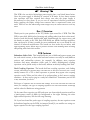
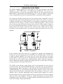
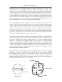
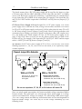
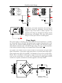
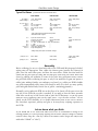
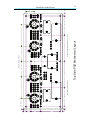
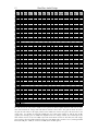
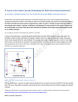
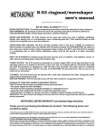
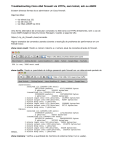
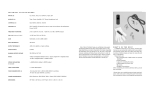
Aikido Stereo 9-Pin PCB
Revision C
USER GUIDE
Introduction
Overview
Schematics
Recommended Configurations
Tube Lists
Assembly Instructions
05/29/2008
GlassWare
AUDIO DESIGN
Copyright 2006-2008© All Rights Reserved
GlassWare Audio Design
A
Warning!
@
This PCB is for use with a high-voltage power supply; thus, a real shock hazard exists.
Once the power supply is attached, be cautious at all times. In fact, always assume
that capacitors will have retained their charge even after the power supply is
disconnected or shut down. If you are not an experienced electrical practitioner,
before applying the B-plus voltage have someone who is experienced review your
work. There are too few tube-loving solder slingers left; we cannot afford to lose any
more.
Rev. C Overview
Thank you for your purchase of the TCJ Aikido 9-pin stereo Rev. C PCB. This FR-4
PCB is extra thick, 0.094 inches (inserting and pulling tubes from their sockets won’t
bend or break this board), double-sided, with plated-through 2oz copper traces, and
the boards are made in the USA. Each PCB holds two Aikido line-stage amplifiers;
thus, one board is all that is needed for stereo unbalanced use or one board for one
channel of balanced amplification. The boards are four inches by ten inches, with
eight mounting holes, which help to prevent excessive PCB bending while inserting
and pulling tubes from their sockets.
PCB Features
Redundant Solder Pads This board holds two sets of differently-spaced solder pads
for each critical resistor, so that radial and axial resistors can easily be used (bulk-foil
resistors and carbon-film resistors, for example). In addition, most capacitor
locations find many redundant solder pads, so wildly differing-sized coupling
capacitors can be placed neatly on the board, without excessively bending their leads.
Dual Coupling Capacitors The boards hold two coupling capacitors, each finding
its own 1M resistor to ground. Why? The idea here is that you can select (via a rotary
switch) between C1 or C2 or both capacitors in parallel. Why again? One coupling
capacitor can be Teflon and the other oil or polypropylene or bee’s wax or wet-slug
tantalum…. As they used to sing in a candy bar commercial: “Sometimes you feel like
a nut; sometimes you don't.”
Each type of capacitor has its virtues and failings. So use the one that best suits the
music; for example, one type of coupling capacitors for old Frank Sinatra recordings
and the other for Beethoven string quartets.
Or the same flavor capacitor can fill both spots: one lower-valued capacitor would set
a low-frequency cutoff of 80Hz for background or late night listening; the other
higher-valued capacitor, 5Hz for full range listening.
Or if you have found the perfect type of coupling capacitor, the two capacitors could
be hardwired together on the PCBs via jumpers J8 and J9, one smaller one acting as a
bypass capacitor for the lager coupling capacitor.
GlassWare Audio Design
2
Introduction to the Aikido
The Aikido amplifier delivers the sonic goods. It offers low distortion, low output
impedance, a great PSRR figure, and feedback- free amplification. The secret to its
superb performance— in spite not using global feedback— lies in its internal symmetry,
which balances imperfections with imperfections. As a result, the Aikido circuit works
at least a magnitude better than the equivalent SRPP or grounded-cathode amplifier.
For example, the Aikido circuit produces far less distortion than comparable circuits by
using the triode’s own nonlinearity against itself. The triode is not as linear as a resistor,
so ideally, it should not see a linear load, but a corresponding, complementary, balancing
non- linear load. An analogy is found in someone needing eyeglasses; if the eyes were
perfect, then perfectly flat (perfectly linear) lenses would be needed, whereas imperfect
eyes need counterbalancing lenses (non-linear lenses) to see straight. Now, loading a
triode with the same triode— under the same cathode-to-plate voltage and idle current
and with the same cathode resistor— works well to flatten the transfer curve out of the
amplifier.
B+
C
6922
Rk
in
Rgs
6922
R15
Rk
out
Rgs
Rg
6922
6922
Rk
Rk
R16
Aikido Amplifier
In the schematic above, the triodes are so specified for example only. Although they
would never fit on the printed circuit board (PCBs), 211 and 845 triodes could be used
to make an Aikido amplifier. The circuit does not rely on 6922 triodes or any other
specific triodes to work correctly. It’s the topology, not the tubes that make the Aikido
special. (Far too many believe that a different triode equals a different topology; it
doesn't. Making this mistake would be like thinking that the essential aspect of being a
seeing-eye dog rested in being a Golden Lab.)
The Aikido circuit sidesteps power supply noise by incorporating the noise into its
normal operation. The improved PSRR advantage is important, for it greatly unburdens
the power-supply. With no tweaking or tube selecting, you should easily be able to get a
-30dB PSRR figure (a conventional grounded-cathode amplifier with the same tubes
and current draw yields only a -6dB PSRR); with some tweaking of resistor R15’s value,
-60dB or more is possible. Additionally, unless regulated power supplies are used for
the plate and heater, these critical voltages will vary at the whim of the power company
and your house’s and neighbors’ house’s use, usually throwing the once fixed voltage
relationships askew. Nevertheless, the Aikido amplifier will still function flawlessly, as it
tracks these voltage changes symmetrically.
GlassWare Audio Design
3
Remember, tubes are not yardsticks that never change, being more like car tires— they
wear out. Just as a tire’s weight and diameter decrease over time, so too the tube’s
conductance. So the fresh 6DJ8 is not the same as that same 6DJ8 after 2,000 hours of
use. But as long as the two triodes age in the same way— which they are inclined to do,
as they do the same amount of work and share the same materials and environment—
the Aikido amplifier will always bias up correctly, splitting the B+ voltage between the
triodes. Moreover, the Aikido amplifier does not make huge popping swings at start
up, as the output does not start at the B+ and then swing down a hundred or so volts
when the tube heats up, as it does in a ground-cathode amplifier.
This circuit eliminates power- supply noise from the output, by injecting the same
amount of PS noise at the top and bottom of the two-tube cathode follower circuit.
The way it works is that the input stage (the first two triodes) define a voltage divider
of 50%, so that 50% of the PS noise is presented to the CF's grid; at the same time the
100k resistors also define a voltage divider of 50%, so the bottom triode's grid also
sees 50% of the PS noise. Since both of these signals are equal in amplitude and phase,
they cancel each other out, as each triodes sees an identical increase in plate current
(imagine two equally strong men in a tug of war contest).
If the output connection is taken from the output cathode follower's cathode, then the
balance will be broken. The same holds true if the cathode follower's cathode resistor
is removed. (Besides, this resistor actually makes for a better sounding cathode
follower, as it linearizes the cathode follower at the expense of a higher output
impedance. Unfortunately, it should be removed and the bypass capacitor C3 should
be used when driving low-impedance headphones, 32- ohms for example. When used
as a line stage amplifier, no cathode resistor bypass capacitors should be used, as these
capacitors are very much in the signal path and very few do not damage the sound,
unless high quality capacitors are used.)
How do I wire up a rotary switch for switching between the two coupling
capacitors? We need a four- pole, three-position switch and some hookup wire. All
four coupling capacitors attach to the input contacts and the two channels of output
can receive either coupling capacitors C1’s or C2’s or both capacitors’ outputs. The
drawing below shows the knob on the faceplate and the rotary switch from behind.
(The switch is shown on the "C1 + C2" position.)
Right Output
C1
Lt C2
Rt C1
C2
Switch Rear
Lt C1
Rt C2
C1 & C2
Switch Front
Left Output
4
GlassWare Audio Design
Heater Issues
The board assumes that a DC 12V power supply will be used for the heaters, so that
6.3V heater tubes (like the 6FQ7 and 6DJ8) or 12.6V tubes (like the 12AU7 or 12AX 7)
can be used. Both types can be used exclusively, or simultaneously; for example 6GC7
for the input tube and a 12BH7 for the output tube. For example, if the input tube (V2
and V3) is a 12AX 7 and the output tube is a 6H30 (V1 and V4), then use jumpers J1, J5
and J6.
6V Heater Power Supply Although designed for a 12V power supply, a 6V heater
power supply can be used with the PCB, as long as all the tubes used have 6.3V heaters
(or 5V or 8V or 18V power supply can be used, if all the tubes share the same 5V or 8V
or 18V heater voltage). Just use jumpers J1 and J4 only. Note: Perfectly good tubes with
uncommon heater voltages can often be found at swap meets, eBay, and surplus stores
for a few dollars each. Think outside 6.3V box. (A 25V heater power supply can be
used, if only 12.6V tubes are used. Just use the jumper settings that are listed on the
PCB for 6V use. For example, if the input tube [V2 and V3] is a 12AX 7 and the output
tube is a 12AU7 [V1 and V4], then use jumpers J1 and J4. )
AC Heaters An AC heater power supply (6.3V or 12.6V) can be used, if the heater
shunting capacitors C7, C8, C9, C10 are left off the board, or are replaced by 0.01µF
ceramic capacitors.
Filament Jumper Wire Schedule
-H
+H
J3
J1 J2
5
V1
4
5
V2
4
J6
J5
4
V3
5
5
V4
4
J4
C8
C7
With a 6.3V PS
Use J2, J3, J5, and J6 only
and all tubes must be
6.3V types.
C9
C10
With a 12.6V PS
Output Tubes V1 and V4:
If tubes are 6V, use J1 only.
If tubes are 12V, use J2 and J3 only.
Input Tubes V2 and V3:
If tubes are 6V, use J4 only.
If tubes are 12V, use J5 and J6 only.
Do not use capacitors, C7, C8, C9, or C10 with an AC heater PS
Since one triode stands atop another, the heater-to-cathode voltage experienced differs
between triodes. The safest path is to reference the heater power supply to a voltage
equal to one fourth the B+ voltage; for example, 75V, when using a 300V power supply.
The ¼ B+ voltage ensures that both top and bottom triodes see the same magnitude of
heater-to-cathode voltage. The easiest way to set this voltage relationship up is the
following circuit:
GlassWare Audio Design
5
B+
DC
Heater
PS
B+
300k
2W
300k
2W
AC
B+
4
0.1µF
250V
B+
4
0.1µF
250V
100k
1/2W
100k
1/2W
Alternatively, you might experiment with floating the
heater power supply, by “grounding” the heater power
supply via only a 0.1µF film or ceramic capacitor. The
capacitor will charge up through the leakage current
between heater and cathodes. Not only is this method
cheap, it is often quite effective in reducing hum.
100
100
B+
4
Power Supply
The power supply is external to the Aikido PCB and can be mounted in, or outside,
the chassis that houses the PCB. The optimal power supply voltage depends on the
tubes used. For example, 6GM8s (ECC86) can be used with a low 24V power supply,
while 6FQ7s work better with a 250-300V B-plus voltage. The sky is not the limit here,
as the heater-to-cathode voltage sets an upward limit of about 400V.
The genius of the Aikido circuit is found in both its low distortion and great PSRR
figure. Nonetheless, a good power supply helps (there is a practical limit to how large a
power-supply noise signal can be nulled). I recommend you use at least a solid, chokefiltered tube or fast-diode rectified power supply. If you insist on going the cheap
route, try the circuit below, as it yields a lot of performance for little money. FRED
rectifiers are expensive, but make an excellent upgrade to the lowly 1N4007.
.01µF
1KV
.01µF
1KV
100mA
high-DCR
.01µF
1KV
.01µF
1KV
All Diodes = 1N4007
All Resistors = 1 ohm 1/2W
6
GlassWare Audio Design
Jumper J7 connects the PCB’s ground to the chassis through the top centermost
mounting hole. If you wish to float the chassis or capacitor couple the chassis to ground,
then either leave jumper J7 out or replace it with a small-valued capacitor (0.01 to
0.1µF). Warning: if rubber O-rings are used with PCB standoffs, then the ground
connection to the chassis is not likely to be made.
Tube Selection
Unlike 99.9% of tube circuits, the Aikido amplifier defines a new topology without fixed
part choices, not an old topology with specified part choices. In other words, an Aikido
amplifier can be built in a nearly infinite number of ways. For example, a 12AX 7 input
tube will yield a gain close to 50 (mu/2), which would be suitable for a phono preamp or
a SE amplifier’s input stage; a 6FQ7 (6CG7) input tube will yield a gain near 10, which
would be excellent for a line stage amplifier; the 6DJ8 or 6H30 in the output stage
would deliver a low output impedance that could drive capacitance-laden cables or even
high-impedance headphones. In other words, the list of possible tubes is a long one:
6AQ8, 6BC8, 6BK7, 6BQ7, 6BS8, 6DJ8, 6FQ7, 6GC7, 6H30, 6KN8, 6N1P, 12AT7,
12AU7, 12AV7, 12AX 7, 12BH7, 12DJ8, 12FQ7, 5751, 5963, 5965, 6072, 6922,
E188CC, ECC88, ECC99… The only stipulations are that the two triodes within the
envelope be similar and that the tube conforms to the 9A or 9AJ base pin-out. Sadly, the
12B4 and 5687 cannot be used with this PCB.
Internal Shields
If the triode’s pin 9 attaches to an internal shield, as it does with the 6CG7 and 6DJ8,
then capacitors, C11 and C12 can be replaced with a jumper, which will ground the
shield. However, using the capacitors will also ground the shield (in AC terms) and allow
using triodes whose pin-9 attaches to the center tap of its heater, such as the 12AU7.
Cathode Resistor Values
The cathode resistor sets the idle current for the triode: the larger the value of the
resistor, the less current. In general, high-mu triodes require high-value cathode resistors
(1-2K) and low-mu triodes require low-valued cathode resistors (100-1k). I recommend
running the output tubes hotter than the input tubes; or put differently, run the input
tubes cooler than the output tubes. Interestingly enough, a lower idle current for the
input stage does not seem to incur the same large increase in distortion that one would
expect in other topologies (a testament to the Aikido’s principle of symmetrical loading).
For example, 1k cathode resistors for the input tube (V2 and V3) and 300-ohm resistors
for the output tubes (V1 and V4), when using 6FQ7s or 6CG7s throughout. Thus, the
output tubes will age more quickly than the input tubes, so rotating output for input
tubes can extend the useful life of the tubes.
Capacitor C3 allows the bottom output triode’s cathode resistor to be bypassed, when
resistor R8 is replaced with a jumper wire; this arrangement is useful when driving lowimpedance loads, such as 300-ohm or 32-ohm headphones, as it provides the lowest
possible output impedance from the Aikido amplifier. If used, C3 should be at least a
1kµF capacitor. On the other hand, if high-capacitance cable is to be driven, use a
higher idle current and retain the cathode resistor, R8, and leave capacitor C3 off.
Current is more important than the lowest possible output impedance.
GlassWare Audio Design
7
Configuring the PCB as a Line Amplifier
The Aikido topology makes a perfect line amplifier, as it offers low distortion, low
output impedance, and excellent power-supply noise rejection— all without a global
feedback loop. The key points are not to use capacitor C3. For guidance on part
values, look at the page 12, which lists several line-amplifier design examples.
Calculating R15’s value is easy; it equals R16 against [(mu -2)/(mu + 2)]. For example,
a triode with a mu of 20 results in R15 = 100k x (20 – 2)/(20 + 2) = 81.8k (82k)
B+
R6
C5
C6
R7
R9
C1
R4
R8
out
J8 (J9)
out
R15
C2
in
R3
R10
R1
C11
C12
R2
R5
(input) V2, V3
Typical Part Values
B+ Voltage =
Heater Voltage =
R1,5,6,7,12,13,14 =
R2,4 =
R3,9,10 =
R8,11 =
R15 =
R16 =
R11
C3
R12
R13
R14
R16
(output) V1, V4
() Parentheses denote recommended values
6CG7 & 6DJ8
6CG7 & 6CG7
12AU7 & 12AU7
12AU7 & 12BH7
170V - 250V (200V)
6.3V
200V - 300V (300V)
6.3V
200V - 300V (250V)
12.6V
200V - 300V (300V)
12.6V
1M
270 - 1k (470)*
100 - 1k (300)*
200 - 330 (200 10mA)*
87.5k
100k
1M
470 - 2k (870)*
Same
270 - 680 (270)*
83.2k
Same
1M
470 - 2k (680)*
Same
180 - 470 (200)*
80k
Same
1M
470 - 2k (1k)*
Same
200 - 470 (523)*
79.3k
Same
Same
"
"
"
"
"
None
Same
"
"
"
"
"
None
*High-quality resistors essential in this position
All resistors 1/2W or higher
C1 =
C2 =
C3 =
C5 =
C6 =
C7,8,9,10 =
C11,12 =
0.1 - 4µF* Film
0.1 - 4µF* Oil
none
1 - 10µF* Film or Oil
0.1 - 1µF* Film or Oil
47µF - 1kµF, 16V
0.1µF 160V(optional)
Same
"
"
"
"
"
Same
*Voltage rating must equal or exceed B+ voltage
(input) V2, V3 =
6CG7, 6FQ7
6CG7, 6FQ7
12AU7, 5814, 5963,
6189, ECC82
12AU7, 5814, 5963,
6189, ECC82
(output) V1, V4=
6DJ8, 6922,
7308, E88CC
6CG7, 6FQ7
12AU7, 5814, ECC82
12BH7, ECC99
GlassWare Audio Design
8
Configuring the PCB as a Headphone Amplifier
The standard Aikido is a thoroughly single-ended affair, nothing pulls while something
else pushes. Unfortunately, wonderful as single-ended mode is sonically, it cannot
provide the larger voltage and current swings that a push-pull output stage can. Singleended stages can only deliver up to the idle current into a load, whereas class-A pushpull stages can deliver up to twice the idle current; and class-AB output stages can
deliver many times the idle current. For a line stage, such big voltage and current swings
are seldom required; headphones, on the other hand, do demand a lot more power;
really, a 32-ohm load is brutally low impedance for any tube to drive. Unfortunately, a
heavy idle current is needed to ensure large voltage swings into low-impedance loads.
B+
C5
R6
C6
R7
R9
C1
R4
in
out
R8
J8 (& J9)
R15
C2
R3
R10
R1
C11
R5
R2
C12
R11
C3
R12
R13
R14
R16
High transconductance output tubes are best for driving headphones, for example, the
6DJ8, 6H30, 12BH7, and ECC99. A coupling capacitor of at least 33µF is required
when driving 300-ohm headphones; 330µF for 32-ohm headphones. Use a high-quality,
small-valued bypass capacitor in C2’s position. Capacitor C3 can be bypassed by placing
a small film capacitor across the leads of resistor R11.
Right HP
output
Left Line Output
Line
Lt C2
Mute
Headphones
Rt C1
Lt C1
Rt C2
Right Line Output
Left HP
Switch Front
GlassWare Audio Design
Typical Part Values
9
() Parentheses denote recommended values
6CG7 & 6DJ8
6CG7 & 6CG7
12AU7 & 6H30
B+ Voltage =
Heater Voltage =
170V - 250V (250V)
6.3V or 12.6V
200V - 300V (300V)
6.3V or 12.6V
200V - 300V (150V)
12.6V
R1,5,6,7,12,13 =
R2,4 =
R3,9,10 =
R8,11 =
R15 =
R16 =
1M
270 - 1k (640 5mA)*
100 - 1k (300)*
200 - 330 (291 10mA)*
87.3k
100k
1M
470 - 2k (640 5mA)*
100 - 1k (300)*
200 - 470 (240 10mA)*
83.2k
100k
1M
470 - 2k (741 3mA)*
100 - 1k (300)*
200 - 470 (74 30mA)*
76.5k
1 00k
*High-quality resistors essential in this position
All resistors 1/2W or higher
C1 =
C2 =
C3 =
C5 =
C6 =
C7,8,9,10 =
C11,12 =
47µF* Film for 300-ohm HP
Same
470µF* for 32-ohm HP
Not recommended
0.47µF* Film or oil
Same
10 - 1kµF, 10V Electrolytic "10 - 1kµF, 16V Electrolytic
1 - 10µF*
"
0.047µF - 1µF* Film or oil
"
10µF-1kµF, 16V Electrolytic
"
0.1µF 160V(optional)
"
Same
470µF* for 32-ohm HP
Same
"
"
Same
None
*voltage rating must equal or exceed B+ voltage
(input) V2, V3 =
6CG7, 6FQ7
6CG7, 6FQ7
12AU7, 5814, 5963,
6189, ECC82
(output) V1, V4 =
6DJ8, 6922,
7308, ECC88
6CG7, 6FQ7
6H30
Assembly
Before soldering, be sure to clean both sides of the PCB with 90% isopropyl alcohol,
wiping away all fingerprints. First, solder the shortest parts (usually the resistors) in
place, then the next tallest parts, and then the next tallest... Make sure that both the
solder and the part leads are shiny and not dull gray. Steel wool can restore luster and
sheen by rubbing off oxidation. If some of the parts have gold-plated leads, remove
the gold flash before soldering the part, as only a few molecules of gold will poison a
solder joint, making it brittle; use sandpaper, steel wool, or a solder pot. NASA forbids
any gold-contaminated solder joints; you should as well. (Yes, there are many quality
parts with gold-flashed leads, but the use of gold is a marketing gimmick.)
Normally, such as when the PCB sits on the floor of its chassis, all the parts sit on the
top side of the PCB (the top side is marked). If you wish to have the tubes protrude
from holes on the top of the chassis (and to place the PCB within 1" of the top panel
with the aid of standoffs), then all the other parts— ex cept the tube sockets— can be
placed on the PCB’s backside; it is a double-sided board after all (be sure to observe
the electrolytic capacitors' polarity and glue or tie-wrap heavy coupling capacitors to
the PCB).
Let me know what you think
If you would like to see some new audio PCB or kit or recommend a change to an
existing product or if you need help figuring out the heater jumper settings or cathode
resistor values, drop me a line by e-mail to the address above (begin the subject line
with either “Aikido” or “tube”).
R1
in
9
7
C11
R3
V3
R2
6
8
R4
R5
R9
C12
9
V4
R11
1
R8
8
3
C3
R10
out
out
out
out
R15
C6
J7
R14
J8 C2
C1
C3
R10
R7
7
9-Pin Aikido Schematic (Rev. C)
2
C2 J8
C1
R12
3
R7
R13
7
C5
R14
6
R16
R6
R13
2
1
R12
B+
8
6
R11
R8
3
1
C12
9
V1
2
R5
R9
3
V2
R6
R2
1
8
R4
R3
7
C11
9
2
6
R1
in
GlassWare Audio Design
.25"
2.00"
1.00"
.50"
.25"
.125R, 4 PLCS
7
8
9
1
2.00"
V1
6 5 4
8 MOUNTING HOLE LOCATIONS
2
3
2.30"
7
9
V2
2.75"
1
2
3
7
9
V3
2.75"
8
1
6 5 4
2
3
2.30"
OVERALL PC BOARD DIMENSIONS: 4.00" x 10.0"
1.60"
Top Side PCB Mechanical Layout
8
6 5 4
1.60"
4 VACUUM TUBE LOCATIONS
7
9
V4
2.00"
8
1
6 5 4
2
3
.25"
0.85"
GlassWare Audio Design
11
GlassWare Audio Design
12
Tube
6AQ8
6BK7
6BQ7
6BS8
6CG7
6CG7
6CG7
6CG7
6CG7
6CG7
6CG7
6DJ8
6DJ8
6DJ8
6DJ8
6DJ8
6DJ8
6DJ8
6FQ7
6GM8
6H30
6H30
6H30
6H30
6H30
6N1P
6N1P
6N1P
6N27P
9AQ8
12AT7
12AU7
12AU7
12AU7
12AU7
12AU7
12AV7
12AV7
12AZ7
12AX7
12AX7
12BH7
12BH7
12BH7
12BH7
12BH7
12BZ7
12DJ8
12FQ7
5687
5687
5687
5687
5751
5963
5965
6072
7119
ECC81
ECC82
ECC83
ECC85
ECC86
B+
Ik(mA)
mu
300V
10.0
57.0
300V
10.0
43.0
300V
10.0
38.0
300V
10.0
36.0
150V
3.0
20.5
200V
5.0
21.1
250V
5.0
21.0
300V
4.5
20.8
300V
7.3
21.4
300V
10.0
21.9
350V
10.0
21.8
100V
5.0
30.2
150V
10.0
30.7
200V
10.0
30.0
250V
10.0
29.6
250V
5.0
28.6
300V
5.0
28.3
300V
8.0
28.9
See 6CG7 and 6SN7
24V
2.0
14.0
100V
20.0
15.4
150V
30.0
15.9
200V
20.0
15.4
250V
20.0
15.4
300V
15.0
15.0
200V
3.0
39.8
250V
5.0
36.0
300V
5.0
35.0
24V
2.0
14.0
See 6AQ8
200V
3.7
60.0
100V
2.5
17.0
150V
3.0
16.6
200V
4.0
16.7
250V
8.0
17.9
300V
10.0
18.1
200V
9.0
37.0
300V
18.0
41.0
See 12AT7
200V
0.5
100.0
300V
1.0
100.0
100V
4.0
16.1
150V
4.0
15.7
200V
5.0
15.9
250V
10.0
17.4
300V
15.0
18.4
300V
100.0
See 6DJ8
See 6SN7
150V
24.0
18.1
200V
20.0
17.5
250V
20.0
17.4
300V
15.0
16.9
200V
0.8
70.0
250V
10.0
21.0
300V
8.2
47.0
300V
2.0
44.0
300V
15.0
21.7
See 12AT7
See 12AU7
See 12AX7
See 6AQ8
See 6GM8
rp
9700
4600
5900
5000
10200
8960
9250
9840
8370
7530
7680
3670
2870
2960
3060
3980
4080
3400
Rk
100
200
191
220
583
397
626
1000
470
243
352
182
124
205
291
673
845
481
R15
93.2k
91.1k
90.0k
89.5k
82.2k
82.7k
82.6k
82.5k
82.9k
83.3k
83.2k
87.6k
87.8k
87.5k
87.3k
86.9k
86.8k
87.1k
R16
100k
100k
100k
100k
100k
100k
100k
100k
100k
100k
100k
100k
100k
100k
100k
100k
100k
100k
R17
170
107
155
139
498
425
440
473
391
344
352
122
93
99
103
139
144
118
Input
Gain
28.1
21.2
18.7
17.8
10.0
10.4
10.3
10.1
10.5
10.8
10.7
15.0
15.2
14.9
14.6
14.0
13.8
14.2
Input
Output
Gain dBs Gain
29.0
0.97
26.5
0.97
25.5
0.96
25.0
0.96
20.0
0.93
20.3
0.93
20.2
0.94
20.1
0.94
20.4
0.94
20.7
0.93
20.6
0.94
23.5
0.96
23.7
0.96
23.4
0.96
23.3
0.96
22.9
0.96
22.8
0.96
23.0
0.96
Output
in dBs
-0.24
-0.27
-0.32
-0.33
-0.59
-0.59
-0.56
-0.53
-0.56
-0.60
-0.57
-0.39
-0.39
-0.37
-0.36
-0.35
-0.34
-0.35
Zo Line
Amp.
248
279
311
321
827
657
820
1063
686
489
576
273
199
274
350
667
787
511
Zo HP
Amp
85
53
78
69
249
212
220
237
196
172
176
61
47
49
52
70
72
59
3400
1140
1040
1310
1380
1670
12200
9480
956
3400
187
69
74
221
294
530
328
221
642
187
75.0k
77.0k
77.7k
77.0k
77.0k
76.5k
90.4k
89.5k
89.2k
75.0k
100k
100k
100k
100k
100k
100k
100k
100k
100k
100k
243
74
65
85
90
111
307
263
27
243
7.0
7.7
7.9
7.7
7.7
7.4
19.4
17.7
17.1
7.0
16.8
17.7
18.0
17.7
17.7
17.4
25.8
25.0
24.7
16.8
0.90
0.91
0.92
0.92
0.93
0.93
0.96
0.96
0.97
0.90
-0.90
-0.80
-0.75
-0.68
-0.66
-0.65
-0.32
-0.36
-0.25
-0.90
357
127
124
267
330
528
539
422
569
357
121
37
33
43
45
56
153
132
14
121
15000
9560
9570
9130
7440
7120
6100
4800
270
427
741
768
336
328
120
56
93.5k
78.9k
78.5k
78.6k
79.9k
80.1k
89.7k
90.7k
100k
100k
100k
100k
100k
100k
100k
250
562
577
547
416
393
165
117
29.1
8.4
8.1
8.2
8.8
8.9
18.3
20.4
29.3
18.4
18.2
18.2
18.9
19.0
25.3
26.2
0.98
0.92
0.92
0.92
0.92
0.92
0.96
0.96
-0.21
-0.75
-0.71
-0.69
-0.71
-0.70
-0.36
-0.35
457
757
959
959
601
581
258
160
125
281
288
273
208
197
82
59
80000
62500
5480
6090
6140
4870
4300
31800
2000
1100
340
706
787
383
267
96.1k
96.1k
77.9k
77.4k
77.7k
79.4k
80.4k
96.1k
100k
100k
100k
100k
100k
100k
100k
100k
800
625
340
388
386
280
234
318
39.0
42.6
8.0
7.7
7.8
8.6
9.1
48.5
31.8
32.6
18.0
17.7
17.8
18.7
19.2
33.7
0.99
0.99
0.92
0.92
0.92
0.93
0.93
0.98
-0.11
-0.12
-0.76
-0.71
-0.68
-0.67
-0.65
-0.17
1719
1238
549
826
877
541
422
292
400
313
170
194
193
140
117
159
1760
1970
2060
2440
58000
6600
7250
25000
2390
37
132
198
397
1250
200
220
1250
324
80.1k
79.5k
79.4k
78.8k
94.4k
82.6k
91.8k
91.3k
83.1k
100k
100k
100k
100k
100k
100k
100k
100k
100k
97
113
118
144
829
314
154
568
110
9.0
8.7
8.7
8.4
30.5
10.4
23.1
20.3
10.7
19.1
18.8
18.7
18.5
29.7
20.3
27.3
26.2
20.6
0.91
0.92
0.93
0.93
0.98
0.93
0.97
0.97
0.95
-0.78
-0.68
-0.65
-0.62
-0.17
-0.63
-0.26
-0.25
-0.48
119
216
276
455
1407
433
337
1272
377
49
56
59
72
414
157
77
284
55
The table above lists many triodes suitable for the 9-pin-based Aikido amplifier PCB. The table lists the same
tube under different B+ voltages and with different cathode resistor values. Two gains are listed: the first is
the gain the tube realizes in the input position in the Aikido; the second is the gain of the same tube in the
output stage. To calculate the final gain multiply the two voltage gains together (or add the gain in dBs
together). For example, given an Aikido line amplifier with a B+ voltage of 300V, and a 6CG7 input tube
with cathode resistors of 1k, and a 6DJ8 output tube with cathode resistors of 481 ohms, the final voltage
gain equals 10.1 from the 6CG7 against the 0.96 gain of the 6DJ8, with a product of 9.7. or, working with dB
instead, 20.1dB plus -.35dB, for a total of 19.75dB. (Aren’t decibels great?)