1
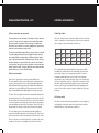
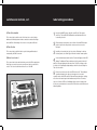
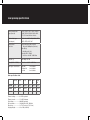
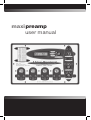
maxipreamp
user manual
introduction
Thank you for your purchase of the MaxiPreamp Digital Tube Tester,
a multi-function measurement station for preamplifier vacuum
tubes. This instrument is the result of over 6 years of engineering
development and has a combination of testing capabilities never
before achieved in such a compact package. The Maxi-Preamp is
simple to use and quick to understand, and a few minutes spent
reading this manual will familiarize you with the operation of the
instrument.
The Maxi-Preamp is an entirely new approach to preamplifier tube
measurement and it is the most comprehensive tester yet in its
testing capabilities. It mounts up to four tubes at a time, and can
simultaneously measure one tube while heating and stabilizing three
others. The instrument uses two proprietary high-performance current
sources, an independent circuit for each section of a tube under test,
to create the most accurate results possible for today’s demanding
listeners. Measurements are scanned by a single precision analog to
digital converter to keep crosstalk and destabilization to a minimum.
Operational control of the unit and test-result calculations are
accomplished by a custom-programmed microprocessor feeding the
backlit LCD display.
The instrument has separate controls for Measurement Function,
Gain Type, Socket Select, Audio Output Level and Section Listen. The
Function control selects the type of test, while the Gain type calibrates
the tester for high, medium and low Mu tube types. The Output Level
controls the audio level at the dual RCA jacks, and the Section Listen
switch allows you to audition each amp in a dual triode individually.
The Noise Test is calibrated in absolute dBV = 1 Vrms and is an audiobandwidth True RMS measurement.
introduction, cont.
measurement functions
Each test socket has in front of it two dual-color LEDs indicating
operational status for the two amp sections in a dual triode - you
get eight individual testers in one package! All tests are continuously
sampled, averaged and then updated to give the most accurate
measurements. Test results are displayed simultaneously for both
sections in the LCD display and updated 4 times each second.
what is measurement?
The Maxi-Preamp can be used by the electronics tech, music store
sales-person or audiophile enthusiast to quickly test a tube for
quality and function. Each of the four test sockets has two bi-color
LEDs indicating operational status for the two amp sections in a dual
triode - you get eight individual testers in one package! All tests are
continuously sampled, averaged and then updated to give the most
accurate measurements. Test results are displayed simultaneously for
both sections in the LCD display and updated 4 times each second.
• Measure preamp tubes for Gain, Transconductance and Noise
• Test any common dual or single preamp triode
• Audition tubes with dual-RCA Direct Audio Output
• Scanning Digital Sampling Converter for highest accuracy
• Continuously sampled/averaged/updated measurements
• Displays both results on LCD simultaneously
• Bi-color operational status LEDs for each tube section
• Two proprietary matched current-source drive circuits
• An entirely new approach to signal tube testing
Vacuum tubes are active devices that are dependent on the circuits
in which they work. The factors they exhibit change depending on how
they are measured. We have all seen the various graphs showing tube
data curves. These graphs represent a tube’s behavior at various operating points of plate voltage, current, input voltage etc. Note that the graphs
are curves - tube behavior varies depending on which operating points are
chosen as test constants.
The function of a tube tester is to provide a common environment in which
to compare different tubes with each other. Any given tube tester has its
specific operating points that it presents to a tube. Thus, measurements
can and usually do differ between testers. This does not mean the data
are incorrect. It only means that the testers are using different standards
to measure a tube.
Published data for tubes showing a certain number, say for transconductance, must also show the other circuit values it was achieved with, or it
is meaningless.
1) Gain Measurement
Gain is the factor by which an amplifier multiplies a signal. It is the product of the output voltage at the plate divided by the input voltage at the
control grid. Gain is a unit-less factor since both measured signals are
voltages.
The MaxiPreamp uses a resistance-coupled voltage gain circuit with a
constant current feature for gain measurement. Each triode element is
furnished with a constant current (1, 2, or 4 milli-amps as set by the
Gain Type switch). A calibrated signal is applied to each control grid and
the resulting change in plate voltage across the load resistor is measured.
Samples are captured every 150 milliseconds, and the microprocessor
then calculates the signal gain as Mu (µ) = change in Vplate / change in
Vgrid. Data are averaged and then updated 4 times per second in the
LCD display.
measurement functions, cont.
switches and controls
2) Transconductance measurement
1) Gain Type switch
Transconductance is a measurement of the ability of a tube to transmit
current. It is the product of the output current in amps divided by the
input voltage at the control grid. Transconductance is significant in
that it shows us the difference in current capability that is generated by
variations in plate impedance between tubes.
This control changes the plate current and cathode resistor in each triode
circuit to compensate for various tube types. Here is a chart showing the
various voltages, currents and cathode resistors in use.
This function in the Maxi-Preamp utilizes a cathode-follower circuit with
a constant voltage low impedance plate supply. Each triode plate in a
pair is supplied with a constant voltage. A calibrated signal is applied
to the control grid inputs and the resulting change in cathode current is
measured. Samples are captured at the tube cathode every 150 milliseconds, and the microprocessor then calculates the transconductance
as Gm = change in Iplate / change in Vgrid. Data are averaged and then
updated 4 times per second in the LCD display.
3) Noise measurement
Each triode is configured as a resistance-coupled amplifier with
the control grid AC coupled to ground. Microphonics and thermal (Johnson) noise are expressed across the output resistor and amplified by a
differential instrumentation amp with a gain of 1000. The amplified noise
signal is fed to a precision RMS-to-DC converter where the true RMS
value of the bandwidth-limited (20Hz–20kHz) noise signal is measured.
The value of the noise signal is referenced to absolute dBV and represented as decibels below 1 Vrms. The measurement is presented on the LCD
for one triode (A or B) at a time using the Tube Section switch. A peak detector circuit captures the maximum signal value within any given update
period and displays that value until the next update. Therefore if a tube is
tapped during noise testing, the peak value of that noise is displayed.
The noise signal is also fed to the adjustable gain audio amplifier for
output at the dual RCA output jacks on the front panel. The Tube Section
switch controls which triode is being auditioned at the RCA jacks. The audio level at the jacks is controlled by the Noise Level knob. Audio output
and tube section select are only available in the Noise Test function.
Gain Ip
Gain Vc
Gm Vp
Gm Rk
Noise
Rp
Noise
Rk
High Mu
1 mA
-1 VDC
200 VDC
1KΩ
100 K Ω
1kΩ
Med Mu
2 mA
-3 VDC
200 VDC
1.5k Ω
100 K Ω
1.5k Ω
Low Mu
4 mA
-6 VDC
200 VDC
1.5k Ω
100 K Ω
1.5k Ω
Ω
It is recommended that suggested Gain Type settings be used. While
other Gain Type settings than what is recommended on the front panel
may be used, spurious or out of range data may result. For instance,
measuring a medium-Mu triode such as a 12AU7 in the High range
setting results in an out of range statement. Using a low or medium gain
setting for a hi-gain triode such as a 12AX7 results in a mismatch of tube
impedance and power supply input resulting in incorrect measurement.
However, neither the tube nor the MaxiPreamp will be damaged by this
action, so it is possible to explore the various combinations of gain and
triode type.
2) Function switch
This switch controls which measurement and which circuit configuration
is being applied to each tube under test. Note that the audio output is
disabled in either the Transconductance or Gain test.
switches and controls, cont.
tube testing procedures
3) Tube Select switch
1
Insert provided IEC power cable into rear AC inlet. Turn power
switch on. The backlit LCD will illuminate and indicate which test
is currently selected.
2
If listening tests are desired, connect either of the dual RCA output
jacks to any line-level input device such as a mixer or receiver
line input.
3
4
Install up to four tubes into the test sockets. Referring to chart on
the front panel, select Gain Type. Allow for 2 minutes warm-up time.
This control selects which socket of the four test sockets is being
addressed. Switching between tubes can be done under all settings
and conditions. No damage to the tester or to any tube will result.
4) Tube Section
This control selects which triode of a pair is being auditioned and
measured by the RMS converter.
5) Noise Level control
This control selects the audio level being sent to the RCA output jacks.
Note that some noise is present even when no tube is mounted in a
socket. The tester has an internal noise floor of -92 dBV.
Select desired measurement function. Results will appear in the LCD
display. For Gain and Transconductance testing, results for both A
and B section are displayed at the same time. For Noise testing, results
for either A or B are displayed depending on which is selected using the
Tube Section switch.
5
Each test socket has two bi-color LEDs in front of it. These indicate
operational status for the tube section under test. In normal
operation mode, both LEDs are lit in Gain and Transconductance testing,
as both sections are being tested simultaneously. In Noise Test mode,
only one of the two LEDs is lit, indicating which section is being tested.
In the event a shorted tube is sensed, the LED on that section will turn red
indicating failure.
maxi preamp specifications
Directly testable tube
types (base 9A)
12AX7, 12AU7, 12AT7, 12AY7, 12DW7,
12BH7, ECC81, ECC82, ECC83, 7025,
5751, 5814 and all other 9A tubes
Optional tube types
(with adaptor)
6DJ8, 6922, 6CW7, 6AQ8, 6GM8, 6EU7,
6CG7, 6FQ7, 6N1P, 5687
Measurement
Functions
Transconductance (Gm, mA/Volt)
Range 0 – 5000 µmhos (Siemens)
Gain (Mu, µ)
Gain Range 0 – 120
Noise (0 dBV = 1VRMS)
Noise floor -92 dBV – 0 dBV Max
Gain (Mu, µ)
Gain Range 0 – 120
Noise (0 dBV = 1VRMS)
Noise floor -92 dBV – 0 dBV Max
Gain Types – dual triodes
High Mu
Medium Mu
Low Mu
1 mA Icathode
2 mA Icathode
4 mA Icathode
Gain specification chart
Gain Ip
Gain Vc
Gm Vp
Gm Rk
Noise
Rp
Noise
Rk
High Mu
1 mA
-1 VDC
200 VDC
1KΩ
100 K Ω
1kΩ
Med Mu
2 mA
-3 VDC
200 VDC
1.5k Ω
100 K Ω
1.5k Ω
Low Mu
4 mA
-6 VDC
200 VDC
1.5k Ω
100 K Ω
1.5k Ω
Filament voltage................ 6.3 VDC regulated
Filament current................ 1.5 A DC Maximum
Plate Voltage..................... 200 VDC regulated
AC input mains.................. 120 (240 Euro) VAC / 50 Watts
Dimensions........................ 12.5” (317 mm) x 8.5” (215 mm)
Shipping Weight................ 9 lbs. 4 Oz. (4.20 kilo)
92
<
h
g
i
H
7
X
A
12
17>
<
w
o
L
7
U
A
12
0>
5
<
d
e
M
7
T
A
12
0>
4
<
d
e
M
12AY7
/20>
0
9
<
d
i/Me
H
7
W
Maxi-Test
12DLLC
6>
1
<
125 North 36th Street | Seattle WA USA 98103
w
o
L
phone 206-633-5190 fax H
206-633-0803
7
B
12
www.maximatcher.com
ECC81
ECC82
ECC83
7025
6DJ8
6922
60>
<
d
e
M
17
<
w
o
L
2
High < 9
2
High < 9
2
Med <
2
Med <