1
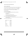
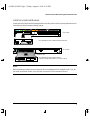
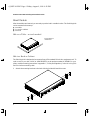
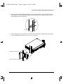
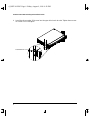
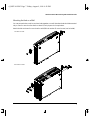
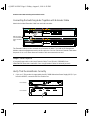
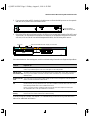
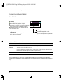
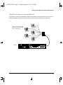
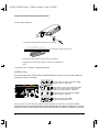
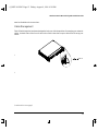
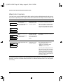
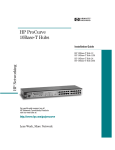
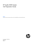
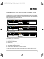
0_INSTAL.FM5 Page 1 Friday, August 9, 1996 4:28 PM
HP AdvanceStack 10BT Switching Hubs Installation Guide
The Switching Hubs are a family of multiport repeaters. With these hubs you can connect computers,
printers, and servers together to exchange files. This guide shows you how to install your Switching
Hub. The three models of the Switching Hubs are:
HP J3200A Switching Hub-12R
HP J3202A Switching Hub-24R
HP J3204A Switching Hub-24T
This installation guide describes how to:
1.
Verify included parts.
2.
Install any optional modules.
3.
Mount the hub.
4.
Connect the hubs together with Extender Cables.
5.
Verify that the hub operates correctly.
6.
Connect network cables using RJ-45 and telco connectors.
Throughout the manuals, these hubs will be abbreviated as the Hub-12R, Hub-24R, and Hub-24T.
1
0_INSTAL.FM5 Page 2 Friday, August 9, 1996 4:28 PM
HP AdvanceStack 10BT Switching Hubs Installation Guide
Verify Included Parts
Each of the three HP Switching Hubs has the following components shipped with it:
■
HP AdvanceStack 10BT Switching Hubs Installation Guide (5964-4661)
■
HP AdvanceStack 10BT Switching Hubs Reference Manual (5964-4662)
■
Topology Examples for the HP Switching Hubs (5182-9815)
■
Warranty booklet
■
Extender Cable (5182-9814)
■
Accessory kit (5063-8570) (shipped with the Hub-12R and Hub-24R):
■
•
two mounting brackets
•
two cable ties
•
four M3 screws to attach brackets to hub
•
four 5/8-inch number 12-24 screws to attach hub to rack
Accessory kit (5063-8603) (shipped with the Hub-24T):
•
■
2
all of the above plus two telco mounting hooks and two 4-40 screws to attach a telco
hook to a telco plug
Power cord, one of the following:
Australia/New Zealand
(8120-6810)
Denmark
(8120-6814)
Europe
(8120-6811)
Japan
(8120-6798)
South Africa
(8120-6813)
Switzerland
(8120-6815)
United Kingdom
(8120-6809)
United States/Canada
(8120-6812)
0_INSTAL.FM5 Page 3 Friday, August 9, 1996 4:28 PM
HP AdvanceStack 10BT Switching Hubs Installation Guide
Install Any Optional Modules
Install optional modules into the Management Slot or the Expansion Slot by following the instructions
in the manuals that accompany these products:
Front of Hub
Management Slot
HP J3210A AdvanceStack 10BT Management Module
Active
Base MAC Address
Back of Hub
Expansion Slot
HP J3212A AdvanceStack Switch Module
(requires Management Module in same hub or stack)
Xcvr
Fault
Requires HP J3210A Management Module
Note
Before installing a module into the Expansion Slot or Management Slot, unplug the hub. If you do
not install an optional module, verify that the cover plate is still screwed into the slot.
3
0_INSTAL.FM5 Page 4 Friday, August 9, 1996 4:28 PM
HP AdvanceStack 10BT Switching Hubs Installation Guide
Mount the Hub
After the modules are inserted, you are ready to put the hub in a stable location. The Switching Hub
can be mounted in three ways:
■ on a table
■ in a rack or cabinet
■ on a wall
Hub on a Table - no tools needed
Sturdy table in an
isolated area.
Hub in a Rack or Cabinet
The Switching Hub is designed to be mounted in any EIA-standard 19-inch telco equipment rack. To
order a rack for your hub, call HP at 1-800-538-8787 to order product number HP 46298D. For your
safety, read the mounting precautions in appendix C, “Safety and Regulatory” in the Switching Hub
Reference before mounting a hub.
1.
4
Attach the mounting brackets to the hub with the included 10-mm M4 screws.
0_INSTAL.FM5 Page 5 Friday, August 9, 1996 4:28 PM
HP AdvanceStack 10BT Switching Hubs Installation Guide
2.
Partially install a screw (5/8-inch number 12-24) into the top hole of a pair of holes 0.5 inches
apart in each rack/cabinet upright. Tighten each screw two turns. Ensure that the screws in
each upright are at the same level.
3.
Place the hub in the rack and lower it so the notches in the bottom of the bracket slide onto the
screws. Tighten these screws-be careful not to overtighten.
Upper hole in the bracket
Lower notch in the bracket
5
0_INSTAL.FM5 Page 6 Friday, August 9, 1996 4:28 PM
HP AdvanceStack 10BT Switching Hubs Installation Guide
4.
Install the other number 12-24 screw into the upper hole in each bracket. Tighten these screwsbe careful not to overtighten.
Install additional screw
6
0_INSTAL.FM5 Page 7 Friday, August 9, 1996 4:28 PM
HP AdvanceStack 10BT Switching Hubs Installation Guide
Mounting the Hub on a Wall
You can put one hub on a wall or stack two hubs together on a wall. Note that a hub should be mounted
only to a wall or wood surface that is at least 1/2-inch plywood or its equivalent.
Attach the hub to the wall or wood surface with 5/8-inch number 12 wood screws (not included):
One hub on a wall:
Two hubs on a wall:
7
0_INSTAL.FM5 Page 8 Friday, August 9, 1996 4:28 PM
HP AdvanceStack 10BT Switching Hubs Installation Guide
Connecting the Switching Hubs Together with Extender Cable
Attach the included Extender Cable from one hub to another:
Extender Cable
(can be installed
in this orientation
only)
The Extender Cable provides communication between the hubs. If you add an HP Management
Module, network management travels over this cable also. You can connect an Extender Cable when
the power is on or off. Never leave an Extender Cable unconnected at one end.
Longer Cables Option
If you need longer cable, order Long Extender Cable 71 cm (28 inch) (5182-9869) from
1-800-538-8787. Note that a maximum of two Long Extender Cables are allowed per stack.
Verify That the Hub Works Correctly
1.
(Optional.) This product is supported by the HP J2962A Redundant Power Supply (RPS). If you
have this HP RPS, connect the RPS to the hub now.
Back of Hub
Back of RPS
8
0_INSTAL.FM5 Page 9 Friday, August 9, 1996 4:28 PM
HP AdvanceStack 10BT Switching Hubs Installation Guide
2.
If you are not using an RPS, plug the included power cord into the hub’s power cord receptacle
and into an AC power source as shown below.
power receptacle
on the back of the hub
3.
Check the LEDs during self test. Initially, all LEDs are on except the Expansion Slot LEDs and
Transceiver if an Expansion Slot Module or transceiver is not installed. After the two second
self test (or 10 second self test with Management Module), the following LEDs are on:
Power on
RPS on if Redundant Power Supply is connected
If the above behavior does not happen, use this troubleshooting information to diagnose the problem:
Condition
Diagnostic Tip
Power LED is OFF Check power cord and power source connections. If connections are secure, then try a different
outlet, or try a different power cord to see if the power cord is the problem.
RPS LED is OFF
The hub is not receiving power from the Redundant Power Supply (RPS) or the cable connection is
and should be ON loose. If you have an RPS connected, check the cable connections. Try connecting the RPS to a
different outlet.
Module Fault LED Turn off the hub and reinsert this module making sure the screws are tightened. If the Fault LED is
is ON
still on, insert the module into a different hub.
Hub Fault LED is
ON
A hub or slot module hardware failure was detected during self-test. Self-test does not complete so
the LEDs will stay on longer than 60 seconds. If you have installed a Switch Module in the stack, verify
that a Management Module is also installed in that stack.
Power cycle the hub. If this condition persists, the hub may have to be replaced. Contact your
HP-authorized dealer or HP representative for assistance.
Hub Fault LED is
flashing
Corresponding LED (such as RPS or port) will also flash at the same time. Make sure SQE is disabled
for the transceiver module if the AUI/Xcvr LED is flashing.
If the above tips do not help, see chapter 3, “Troubleshooting” in the Switching Hubs Reference
Manual for additional information.
9
0_INSTAL.FM5 Page 10 Friday, August 9, 1996 4:28 PM
HP AdvanceStack 10BT Switching Hubs Installation Guide
Connecting Network Cables
Using RJ-45 Connectors
To connect:
Push the RJ-45 plug into the RJ-45 jack
until the tab on the plug clicks into place.
When power is on for the hub and the connected
device, the Port LED should light to confirm
a powered-on device (e.g., end node) is at the
other end of the cable.
RJ-45 plug
To disconnect:
Press the small tab on the plug and
pull the plug out of the jack.
unshielded twisted-pair cable
Category 3, 4, or 5
Cat 3, 4 maximum distance: 100 meters
Cat 5 maximum distance: 150 meters
If the Port LED is not on, use this table to solve the problem:
Condition
Diagnostic Tip
Port LED is still off Try:
when a cable is
- For the indicated port, verify that both ends of the cabling are snug: hub and end node.
connected
- Verify the end node and hub are both on.
- A different port or a different cable.
If you have installed the Management Module, use the ASCII console or HP AdvanceStack Assistant
to determine the state of the port and re-enable the port if desired.
Note
Do not use twisted-pair, thin coax, or fiber cables to make a Switching Hub to Switching Hub
connection across the stack. The Extender Cable is for Switching Hub to Switching Hub connections
only.
10
0_INSTAL.FM5 Page 11 Friday, August 9, 1996 4:28 PM
HP AdvanceStack 10BT Switching Hubs Installation Guide
Using Telco Connectors with the Hub-24T
If you prefer to make your twisted-pair connections through a cross-connect block, wiring closet, or
other intermediary connection, the Hub-24T has industry-standard 50-pin telco connectors.
Devices connected to the hub’s
50-pin telco connector through
a cross-connect block.
Hub-24T
11
0_INSTAL.FM5 Page 12 Friday, August 9, 1996 4:28 PM
HP AdvanceStack 10BT Switching Hubs Installation Guide
To use a telco connector:
1. Attach the mounting hook with the 1/2-inch 4-40 screw.
2. Insert hook in slot on the hub’s face.
3. Pivot the telco plug onto the connector and press into place.
4. Tighten the screw on the telco plug. Be careful not to overtighten the
screw.
To remove a telco connector, reverse this process.
AUI/Xcvr Slot
An optional transceiver module can be installed in the hub’s AUI/Xcvr slot to provide additional
connectivity choices, including:
HP Fiber-Optic Transceiver Module (HP J2606A)
Maximum Distance: 1000 meters
HP Twisted-Pair Transceiver Module (HP J2607A
Category 3, 4 maximum Distance: 100 meters
Category 5 maximum Distance: 150 meters
HP ThinLAN Transceiver Module (HP J2608A)
Maximum distance: 185 meters
HP AUI Port Module (HP J2609A)
(to attach external transceivers)
Do not use this port for Switching Hub to Switching Hub connections in the stack. See the
documentation accompanying the optional transceiver modules for cabling configurations for those
modules. To use an external transceiver on a hub, the SQE Test and Loopback Test options, if present,
12
0_INSTAL.FM5 Page 13 Friday, August 9, 1996 4:28 PM
HP AdvanceStack 10BT Switching Hubs Installation Guide
must be disabled on the transceiver.
Cable Management
The HP Switching Hubs have been designed to help you with the problem of managing your network
cables. On both sides of the front of each hub are two holes that accept a cable tie to tie-wrap your
cables:
cable tie
(continued on next page)
13
0_INSTAL.FM5 Page 14 Friday, August 9, 1996 4:28 PM
HP AdvanceStack 10BT Switching Hubs Installation Guide
Where to Go From Here
Your hub is now correctly installed and is able to send and receives data between end nodes, servers,
and printers. Depending on your setup, use this table to determine what steps need to be taken next.
Your Hub Setup
Mgmt.
Detailed Description
Communication Status
What You Need to Do
One hub or stack of 2 or
more hubs with:
- No Management Module
- No Switch Module
All users are on segment 1 and can communicate together.
No software configuration needed.
Stack of 2 or more hubs
with:
- Management Module
- Switch Module
All users are distributed evenly over segments 1, 2, 3, and 4 and
can communicate together.
No software configuration or optimization needed.
Stack of one or more hubs
with Management Module
only
All users are on segment 1 and can communicate together.
If Act and Col LEDs are on most of the
time, segment your stack by either:
-adding a Switch Module
-adding more LAN adapters to the
servers.
- adding an external switch.
If Act or Col LEDs are on all of the time,
add a Management Module and external switch or Switch Module to distribute ports evenly over the four segments.
Switch in back
Mgmt
If you only add a Management Module
and move the ports to other segments in
software, remember that users cannot
communicate between the segments.
Add an external switch or Switch Module to this stack for communication between all the segments.
If you need to set the IP address, see the Management Module manual for information on how to use
the ASCII console or HP AdvanceStack Assistant. For a Novell Netware network, no configuration
is necessary.
14
0_INSTAL.FM5 Page 15 Friday, August 9, 1996 4:28 PM
0_INSTAL.FM5 Page 16 Friday, August 9, 1996 4:28 PM
Technical information in this document is
subject to change without notice.
All rights reserved. Reproduction, adaptation, or translation without prior written permission is prohibited except as allowed
under the copyright laws.
© 1996 Hewlett-Packard Company
HP Part Number: 5964-4661
Edition 1, August 1996
Printed in Singapore.
*5964-4661*