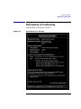
1
HP-PB 100VG-AnyLAN Network Adapter
Installation and Service
HP 3000 MPE/iX Computer Systems
Edition 1
B5426-90001
E0897
Printed in: U.S.A. August 1997
Notice
The information contained in this document is subject to change without
notice.
Hewlett-Packard makes no warranty of any kind with regard to this
material, including, but not limited to, the implied warranties of
merchantability or fitness for a particular purpose. Hewlett-Packard
shall not be liable for errors contained herein or for direct, indirect,
special, incidental or consequential damages in connection with the
furnishing or use of this material.
Hewlett-Packard assumes no responsibility for the use or reliability of its
software on equipment that is not furnished by Hewlett-Packard.
This document contains proprietary information which is protected by
copyright. All rights reserved. Reproduction, adaptation, or translation
without prior written permission is prohibited, except as allowed under
the copyright laws.
Restricted Rights Legend
Use, duplication, or disclosure by the U.S. Government is subject to
restrictions as set forth in subparagraph (c) (1) (ii) of the Rights in
Technical Data and Computer Software clause at DFARS 252.227-7013.
Rights for non-DOD U.S. Government Departments and Agencies are as
set forth in FAR 52.227-19 (c) (1,2).
Hewlett-Packard Company
3000 Hanover Street
Palo Alto, CA 94304 U.S.A.
© Copyright 1997 by Hewlett-Packard Company
2
Contents
HP-PB 100VG-AnyLAN Network Adapter Installation at a Glance 9
Installation Overview . . . . . . . . . . . . . . . . . . . . . . . . . . . . . . . . . . . . . . . .10
Product Description . . . . . . . . . . . . . . . . . . . . . . . . . . . . . . . . . . . . . . . .10
Product Contents . . . . . . . . . . . . . . . . . . . . . . . . . . . . . . . . . . . . . . . . . .10
Tools and Accessories . . . . . . . . . . . . . . . . . . . . . . . . . . . . . . . . . . . . . . .10
In This Book. . . . . . . . . . . . . . . . . . . . . . . . . . . . . . . . . . . . . . . . . . . . . . . .11
1. Installation Procedure
1. Prepare to Install the Adapter . . . . . . . . . . . . . . . . . . . . . . . . . . . . . . .14
Observe Antistatic Precautions . . . . . . . . . . . . . . . . . . . . . . . . . . . . . . .14
Verify Product Contents . . . . . . . . . . . . . . . . . . . . . . . . . . . . . . . . . . . . .14
Record Adapter Information . . . . . . . . . . . . . . . . . . . . . . . . . . . . . . . . .15
Gather Tools and Accessories . . . . . . . . . . . . . . . . . . . . . . . . . . . . . . . .16
2. Shut Down the Operating System and Switch Off the Computer . . .17
3. Install the Adapter . . . . . . . . . . . . . . . . . . . . . . . . . . . . . . . . . . . . . . . .18
a. Access the adapter slot(s). . . . . . . . . . . . . . . . . . . . . . . . . . . . . . . . . .18
b. Select an available slot. . . . . . . . . . . . . . . . . . . . . . . . . . . . . . . . . . . .18
c. Insert the adapter into the slot . . . . . . . . . . . . . . . . . . . . . . . . . . . . .18
d. Switch on the power to the computer. . . . . . . . . . . . . . . . . . . . . . . . .19
4. Attach the Adapter to the Network . . . . . . . . . . . . . . . . . . . . . . . . . . .20
5. Configure the Adapter into the System . . . . . . . . . . . . . . . . . . . . . . . .21
6. Verify Operation . . . . . . . . . . . . . . . . . . . . . . . . . . . . . . . . . . . . . . . . . .22
2. Service Information
Field Replaceable Units . . . . . . . . . . . . . . . . . . . . . . . . . . . . . . . . . . . . . .24
Exchange Assembly . . . . . . . . . . . . . . . . . . . . . . . . . . . . . . . . . . . . . . . .24
Troubleshooting Tools . . . . . . . . . . . . . . . . . . . . . . . . . . . . . . . . . . . . . . . .25
Card LEDs . . . . . . . . . . . . . . . . . . . . . . . . . . . . . . . . . . . . . . . . . . . . . . .25
3
Contents
Removal/Replacement Instructions. . . . . . . . . . . . . . . . . . . . . . . . . . . . . 27
Removal/Replacement of the Adapter . . . . . . . . . . . . . . . . . . . . . . . . . 28
Reshipment Guidelines . . . . . . . . . . . . . . . . . . . . . . . . . . . . . . . . . . . . . . 29
Technical Specifications . . . . . . . . . . . . . . . . . . . . . . . . . . . . . . . . . . . . . . 30
Declaration of Conformity . . . . . . . . . . . . . . . . . . . . . . . . . . . . . . . . . . . . 31
Glossary
4
Figures
Figure 1-1 . Address Location . . . . . . . . . . . . . . . . . . . . . . . . . . . . . . . . . .15
Figure 1-2 . Inserting and Securing Adapter . . . . . . . . . . . . . . . . . . . . . .19
Figure 1-3 . Port Connection . . . . . . . . . . . . . . . . . . . . . . . . . . . . . . . . . . .20
Figure 2-1 . Declaration of Conformity. . . . . . . . . . . . . . . . . . . . . . . . . . .31
5
Figures
6
Tables
Table 1-1. LED Patterns . . . . . . . . . . . . . . . . . . . . . . . . . . . . . . . . . . . . . .22
Table 2-1. Troubleshooting Checklist . . . . . . . . . . . . . . . . . . . . . . . . . . . .26
Table 2-2. 100VG Network Adapter Technical Specifications. . . . . . . . .30
7
Tables
8
HP-PB 100VG-AnyLAN Network
Adapter Installation at a Glance
The following figure shows how to install the HP-PB 100VG-AnyLAN
Network Adapter.
9
Installation Overview
The installation procedure includes the following major steps:
1. Prepare to install the adapter.
2. Shut down the operating system and switch off the power to the
computer.
3. Install the adapter.
4. Attach the adapter to the network.
5. Configure the adapter.
6. Verify operation.
Product Description
The HP-PB 100VG-AnyLAN Network Adapter provides the hardware
needed to interface an HP-PB backplane to a 100VG-AnyLAN Network.
The HP-PB 100VG-AnyLAN Network Adapter has the following
features:
• one built-in connector: an RJ-45 connector, for attachment to the hub
• 10 or 100-Mbit per second operation
• single-high form factor
Product Contents
• HP-PB 100VG-AnyLAN Network Adapter — A3496-60001
• Installation and Service Manual — B5426-90001
Tools and Accessories
Before installation, gather these tools and accessories:
• screwdrivers necessary for opening your computer and installing
adapters
• grounding wrist strap
• cable for attachment to hub, UTP category 3 or 5
10
In This Book
This book is the installation and service manual for the HP-PB
100VG-AnyLAN Network Adapter that connects an HP 3000 computer
using the HP-PB backplane to a 100VG-AnyLAN network.
The installation procedure section contains the installation instructions.
It explains in detail the steps necessary to install the adapter into your
computer.
The service information section defines the steps and procedures to
follow if you experience trouble with the adapter. It explains diagnostics
to be used for troubleshooting, removal/replacement instructions,
reshipment guidelines, and technical specifications.
NOTE
This manual is limited to installation of the HP-PB 100VG-AnyLAN
Network Adapter only. It is assumed network hubs and cabling are in
place and the appropriate HP-PB 100VG-AnyLAN network software and
operating system have already been installed on the computer.
11
12
1
Installation Procedure
This section contains installation instructions for the HP-PB
100VG-AnyLAN Network Adapter. The instructions are organized into
six primary steps listed below. Each step is described in detail in this
section. If the adapter has already been installed at the factory, you may
proceed directly to step 4.
1. Prepare to install the adapter.
2. Shut down the operating system and switch off the computer.
3. Install the adapter.
4. Attach the adapter to the network.
5. Configure the adapter into the system.
6. Verify operation.
13
Installation Procedure
1. Prepare to Install the Adapter
1. Prepare to Install the Adapter
Before installing the adapter, you should perform the following steps:
1. Observe antistatic precautions.
2. Verify product contents.
3. Record adapter identification information.
4. Gather tools and accessories.
Observe Antistatic Precautions
This product contains electronic components that can easily be damaged
by small amounts of static electricity. To avoid damage, follow these
guidelines:
• Store adapters in their conductive plastic bags until you are ready to
install them.
• If possible, work in a static-free area.
• Handle adapters only by the edges. Do not touch electronic
components or electrical traces. We strongly recommend that you use
a grounding wrist strap that is connected to the metallic chassis of
the computer. If you do not have a wrist strap, touch the chassis
before handling adapters, and frequently or continuously thereafter,
to equalize any static charge.
Verify Product Contents
Unpack and identify all items supplied with the products:
Part Numbers
• HP-PB 100VG-AnyLAN Network Adapter
A3496-60001
• Installation and Service Manual
B5426-90001
14
Chapter 1
Installation Procedure
1. Prepare to Install the Adapter
Record Adapter Information
Record the relevant information from the card here for future reference.
If your adapter requires service in the future this information will be
needed by HP service personnel.
Card
Information
Example
Motherboard Model and Revision number
__________________
H05000-003, REVB02
Daughter Card Model and Revision number
__________________
H04522-001, REVC00
Daughter Card Serial number
__________________
615385
Daughter Card Station Address
__________________
0060B0D52EFC
Information to Record
This information is provided on stickers affixed to various locations on
the adapter cards. Use Figure 1-1, for the locations of the relevant
information.
Figure 1-1
Address Location
Chapter 1
15
Installation Procedure
1. Prepare to Install the Adapter
Gather Tools and Accessories
Check the hardware installation manual of your computer model for
special tools and accessories required to access the I/O adapter slot(s).
The following common tools are helpful:
• screwdrivers necessary for opening your computer and installing
adapters
• grounding wrist strap
NOTE
You should have all of your system and peripheral device manuals
available for reference. There may be special system or device dependent
requirements that are not noted here.
16
Chapter 1
Installation Procedure
2. Shut Down the Operating System and Switch Off the Computer
2. Shut Down the Operating System and
Switch Off the Computer
1. Before installing the HP-PB 100VG-AnyLAN Network Adapter,
ensure that the operating system is shut down. Refer to your
computer system manuals for proper shutdown procedures to avoid
corruption or loss of data.
2. Ensure that power to the host computer is switched off and
disconnected from the source power supply.
WARNING
Unless otherwise noted in your computer system manuals,
failure to properly shut down the system and remove power may
create a personnel hazard, or may result in hardware damage or
data corruption.
Chapter 1
17
Installation Procedure
3. Install the Adapter
3. Install the Adapter
To install the adapter in the host computer, perform the following steps:
a. Access the adapter slot(s).
b. Select an available adapter slot.
c. Insert the adapter into the slot.
d. Switch on the power to the computer.
a. Access the adapter slot(s)
Because computer models vary, there may be different procedures to
access and select an adapter slot. Before you install the adapter, you
should refer to the manuals that apply to your particular computer for
instructions. Identify the following information:
• authorized or recommended adapter configurations and limitations,
if any
• how to access the computer’s adapter slot(s)
• proper orientation of the adapter in its slot
b. Select an available slot
Select an available HP-PB adapter slot. Remove the slot cover for that
slot. Refer to your computer system administrator’s documentation.
Retain the cover for possible future use.
Verify you can see an adapter connector at the back of the slot.
Record the slot number for future reference. If there are no other
adapters to install, reassemble the computer.
c. Insert the adapter into the slot
Insert the adapter into the adapter slot connector and press in firmly
until the adapter is fully seated into the connector. Refer to Figure 1-2.
1. With both hands, grasp the adapter by its edges or faceplate. Do not
touch electronic components or electrical traces.
18
Chapter 1
Installation Procedure
3. Install the Adapter
2. Insert the adapter into the slot. Be sure the contacts and adapter
guides are properly aligned.
3. Fold in the extractor levers.
4. Press the adapter firmly until you feel the connector mate fully.
5. Secure the adapter in its slot by securing the retaining screws.
Figure 1-2
Inserting and Securing Adapter
d. Switch on the power to the computer.
1. Reconnect the source power supply to the computer.
2. Switch on the computer power switch.
Chapter 1
19
Installation Procedure
4. Attach the Adapter to the Network
4. Attach the Adapter to the Network
Use the RJ-45 connector for connecting a UTP category 3 or 5 cable
(not supplied) to a 100VG-AnyLAN hub or 10Base-T hub/switch. Refer to
Figure 1-3..
Figure 1-3
Port Connection
Attach the cable to the RJ-45 connector by following these steps:
a. Plug the cable into the RJ-45 connector.
b. Secure the other end of the cable to the 100VG-AnyLAN hub or
10Base-T hub/switch.
c. If necessary, reconfigure the hub/switch port to operate at the desired
speed and duplex settings.
NOTE
All of the LEDs on the adapter (except the Power LED) are initialized by
software when the link is started on the system. Therefore, until
software initializes the adapter, the state of the LEDs cannot be reliably
interpreted.
20
Chapter 1
Installation Procedure
5. Configure the Adapter into the System
5. Configure the Adapter into the System
On MPE systems you will need to configure the adapter into the system.
In particular you must specify link speed and duplex settings to match
those of the network hub/switch port to which you attached the adapter.
For more information on MPE systems, refer to:
• NS3000/iX NMMGR Screens Reference Manual (36922-61003)
• HP3000/iX Network Planning and Configuration Guide
(36922-61023)
• System Startup, Configuration, and Shutdown Reference Manual
(32650-90042)
Chapter 1
21
Installation Procedure
6. Verify Operation
6. Verify Operation
Verify proper operation of the HP-PB 100VG-AnyLAN Network Adapter
by checking the LEDs on the card. When the computer is switched on,
the Power LED will come on. At this point, the rest of the LEDs are in an
uninitialized state, and cannot be used until the driver on the system has
been started. After the driver has been started, the following Table 1-1,
may be used to interpret the LED patterns.
Table 1-1
LED Patterns
LED
LED on
LED off
Test
Driver has detected a
fatal condition and is no
longer operating.
Adapter is functioning
correctly.
10
Adapter is operating at
10Mbps.
Adapter is not operating at
10Mbps.
100
Adapter is operating at
100Mbps.
Adapter is not operating at
100Mbps.
Link
Adapter is correctly
receiving a link signal
from the hub/switch.
Adapter is not receiving a
link signal from the
hub/switch.
Activity
Adapter is sending or
receiving a packet to/from
the hub/switch.
No packet is currently being
transferred to/from the
hub/switch.
Power
Adapter is receiving
power from the system.
The system is not supplying
power, or the adapter is not
seated properly in the slot.
22
Chapter 1
2
Service Information
This section provides the following service information:
• Field Replaceable Units
• Troubleshooting Tools
• Removal/Replacement Instructions
• Reshipment Guidelines
• Technical Specifications
23
Service Information
Field Replaceable Units
Field Replaceable Units
Field Replaceable Units (FRUs) are assemblies or components that are
authorized for field replacement.
There are no FRUs on this adapter. If there should be a problem the
entire adapter is replaceable.
Exchange Assembly
The HP-PB 100VG-AnyLAN Network Adapter may be replaced under
the HP board exchange program. Adapter part numbers are listed below:
24
New Adapter
A3496-60001
Exchange Adapter
A3496-69001
Chapter 2
Service Information
Troubleshooting Tools
Troubleshooting Tools
Troubleshooting tools are used to identify faulty adapters. For this
product, the following tools are available:
• troubleshooting checklist (see Table 2-1)
• VGPBA online diagnostic (has online help)
Card LEDs
The 6 LEDs on the back of the card can be used to determine the state of
the adapter while the driver on the system is running.
NOTE
All of the LEDs on the card (except the Power LED) are initialized by the
driver when the link is started on the system. Therefore, until the driver
initializes the card, the state of the LEDs cannot be reliably interpreted.
The Power LED will be on at any time power is applied to the system. To
interpret the other LEDs, the driver must be running. The following
Table 2-1, can be used to determine a possible problem.
Chapter 2
25
Service Information
Troubleshooting Tools
Table 2-1
Troubleshooting Checklist
LED state
Power LED off
Possible cause
Solution
No power applied to card
Check power to HP-PB bus/system,
verify adapter is properly seated in
its slot.
Blown fuse
Replace the adapter
Test LED on
Driver has detected a fatal
hardware or software condition
Consult console and/or log files for
error messages. Retry the
operation. If necessary, contact HP
or replace the adapter.
Link LED off
Card is not receiving link signals
from hub/switch
Verify link has been started by the
operator. If so, verify proper
configuration of the link and the
hub/switch port. Check/replace the
cable.
Activity LED off
Card is not sending or receiving
data to/from the hub/switch
This condition is normal when the
link LED is off or when the hub is
not sending or receiving data
to/from the adapter. If you believe
data is being sent/received, check
the hub/switch port configuration,
and also the network and/or MAC
address configuration for the link.
26
Chapter 2
Service Information
Removal/Replacement Instructions
Removal/Replacement Instructions
This section describes removal and replacement for the
HP-PB 100VG-AnyLAN Network Adapter.
WARNING
Unless otherwise noted in your system manuals, removal of the
network adapter should only be done with power removed from
the host computer. Failure to comply may result in an electrical
shock hazard, or in damage to the hardware.
CAUTION
The adapter contains electronic components that can be damaged by
static electricity. To avoid damage, follow these guidelines:
• Store adapters in their conductive plastic bags.
• If possible, work in a static-free area.
• Handle adapters only by the edges. Do not touch electronic
components or electrical traces. We strongly recommend that you use
a grounding wrist strap that is connected to the metallic chassis of
the computer. If you do not have a wrist strap, touch the chassis
before handling adapters, and frequently or continuously thereafter,
to equalize any static charge.
Chapter 2
27
Service Information
Removal/Replacement Instructions
Removal/Replacement of the Adapter
For adapter removal, follow the procedures below:
1. Before removing the card, ensure that the operating system is shut
down and power to the host computer is switched off. Consult your
computer documentation for proper shutdown procedures to avoid file
corruption or loss of data.
2. Disconnect all cabling from the adapter.
3. Consult your computer documentation for instructions on the best
method for accessing the adapter slots.
4. Unscrew the two retaining screws and pull extractor levers out.
5. While holding extractor levers, slide the adapter out of its slot.
6. Place adapter in an antistatic bag.
7. Install a slot cover for proper cooling and RFI suppression.
To install a replacement adapter, follow the procedures described in the
installation section.
28
Chapter 2
Service Information
Reshipment Guidelines
Reshipment Guidelines
If any item of the product is to be returned to Hewlett-Packard for any
reason, contact your HP Sales and Support Office to coordinate the
return.
When returning the item, attach a tag that identifies the owner and
indicates the reason for shipment. Include all relevant information,
which includes model, serial, station, and revision numbers.
Pack the item in the original factory packaging material if available, or a
suitable substitute. Provide antistatic protection to applicable
components or assemblies.
Chapter 2
29
Service Information
Technical Specifications
Technical Specifications
The network adapter technical specifications are provided in Table 2-2.
Table 2-2
Specifications
100VG Network Adapter Technical Specifications
Safety
• UL 1950, 2nd Edition
• CSA 22.2 No 950, 2nd Edition
• IEC 950 (1991)/EN 60950 (1992)
Communication
Standards
• IEEE 802.12 (1995) 100 Mb/s Ethernet framing
Immunity
Standards
• ESD: IEC 801-2: 1991 4kV CD, 8 kV AD
• IEEE 802.3 Type 10Base-T 10 Mb/s
• Radiated Immunity: IEC 801-3: 10 V/m
• EFT/Burst: IEC 801-4: (1988) 0.5 kV signal lines,
1.0 kV power line
Electrical
Characteristics:
3.30 A @ 5 V typical; 3.40 A @ 5 V maximum
Physical
Dimensions:
18 cm. by 8.9 cm. (7.4 in. by 3.5 in.)
Weight:
290 g. (10.2 oz.)
Temperature
Operating: 0˚C (32˚ F) to 55˚C (131˚F)
Environmental
Storage: -40˚C (-40˚F) to 70˚C (158˚F)
Humidity
Operating: 15% to 80% Relative, non-condensing
Storage: 5% to 95% Relative, non-condensing
Altitude:
Operating: 3,050 meters (10,000 feet)
Storage: 4,600 meters (15,000 feet)
Emissions
Standards:
• FCC Class A
• CISPR 22 (1993) Class A
• VCCI Class A
30
Chapter 2
Service Information
Declaration of Conformity
Declaration of Conformity
A declalaration of conformity is shown in .
Figure 2-1
Declaration of Conformity
Chapter 2
31
Service Information
Declaration of Conformity
32
Chapter 2
Glossary
Numbers
C
100VG-AnyLAN Refers to the
100Mbit/s network technology over
voice grade cable that is
compatible with the IEEE 802.12
standard. This technology
guarantees access to any end node
that request to transmit, which
ensuring priority access to end
nodes that require consistent,
continuous access for application
such as full-motion video or video
conferencing. See also: Demand
Priority Protocol.
CAT Category A cable quality
rating. 100VG-AnyLAN supports
CAT-3 or 5 UTP cable. See LAN
cable.
A
adapter An add-on computer
interface card and circuitry that
provides the physical connection
and data translation between the
host computers’s I/O bus and
external devices or networks.
adapter slot The location where
adapters attach to the backplane.
B
backplane For an I/O bus. The
computer’s circuitry and
connectors to which adapter cards
connect.
Glossary
collision The result of two or
more nodes on an 802.3 network
transmitting at the same time,
producing a garbled transmission.
D
Demand Priority Protocol A
request-based protocol that is
deterministic—a network end node
connected to a 100VG hub makes a
request (or “demand”) to transmit,
and then can transmit only when
authorized by the hub. Under hub
control, the Demand Priority
Protocol guarantees network
access for any end node that
requests to transmit data.
driver A portion of system code
that allows communication
between the operating system and
the network card.
E
Ethernet A LAN that uses the
CSMA/CD method of access and
transmits at 10Mbit/s on a bus or
33
Glossary
star topology. The IEEE 802.3
standard evolved from Ethernet,
but they are not exactly the same.
Network devices based on both
standards can co-exist on the same
medium, but they cannot exchange
data directly without special
“bilingual” software that can
decode packets of both types. The
drivers for the HP3000 network
cards fit this requirement if
configured correctly.
Ethernet address See station
address.
H
HP-PB HP Precision Bus. Refers
to the hardware I/O architecture.
The precision bus is the bus thru
which these cards communicate
with the CPU and memory.
Ethernet, but the two networks are
not fully compatible with each
other.
IEEE 802.5 standard Part of the
institute of Electrical and
Electronics Engineers 802 family
of LAN standards. The 802.5
standard defines the physical layer
(layer 1) and the Medium Access
Control (MAC) portion of the data
link layer (layer 2). Used with
Token Ring networks.
IEEE 802.12 standard Part of
the institute of Electrical and
Electronics Engineers 802 family
of LAN standards. The 802.12
standard defines the physical layer
(layer 1) and the Medium Access
Control (MAC) portion of the data
link layer (layer 2).
L
I
LAN See local area network.
IEEE 802.3 standard Part of the
institute of Electrical and
Electronics Engineers 802 family
of LAN standards. The 802.3
standard defines the physical layer
(layer 1) and the Medium Access
Control (MAC) portion of the data
link layer (layer 2). The IEEE
802.3 standard evolved from
34
LAN cable The medium through
which data moves in a LAN, LAN
cables come in many types. For
example, thick (10 mm) coaxial
cable, thin (5 mm) coaxial cable,
fiber-optic cable, and shielded or
unshielded twisted-pair cable. The
100VG-AnyLAN cables are
typically UTP CAT-3 or CAT-5.
Glossary
Glossary
LED See light emitting diode.
light emitting diode A small
light on a device that is often used
to provide status information.
link beat A periodic signal
transmitted in Ethernet and
IEEE 802.3 Type 10Base-T
networks to inform one station of
device of the presence of another. It
also helps verify the integrity of
the network link between them.
(Also called “link test pulse”.)
local area network A generalpurpose communications network
that interconnects a variety of
devices within a limited
geographical area. A LAN might
connect computers on adjacent
desks, within a building, or within
several buildings of a campus.
M
MAC address See station
address.
Mbits/ Megabits per second
defined as (1,000,000 bits per
second).
cables (fiber-optic or copper),
although radio and other broadcast
media are possible.
N
node A station; a physical device
that allows for the transmission of
data within a network.
P
packet A bit stream consisting of
predefined fields that contain data,
addresses, and control
information. In the IEEE 802.3
environment this structure is often
referred to as the ‘MAC frame”.
Packet is the more commonly used
term, and originated in the
Ethernet environment.
Precision Bus See HP-PB.
protocol The set of rules
governing the operation of
functional units of a
communication system that must
be followed if communication is to
be achieved.
medium, media The
transmission connection between
nodes. Most current LANs use
Glossary
35
Glossary
R
ring network A network
configuration where a series of
attaching devices are connected by
unidirectional links to form a
closed path.
ring topology A logically circular,
unidirectional transmission path
without defined ends. Control can
be distributed or centralized. See
topology.
RJ-45 A standard defining the pin
assignments for an 8-pin modular
plug for 4-pair twisted wire
network cable.
S
slot The physical place in the back
of the computer where a card plugs
in. Each slot has a number.
star topology A logically starshaped network layout where all
traffic is passed through a single
point (usually a hub). Hubs can
then be connected to form multiple
starts.
Station address A 12-digit
hexadecimal number that
identifies a specific network node,
and allows messages to be directed
36
to that node only. The first 6 digits
are the same for all cards from a
particular manufacturer. Each
manufacturer is assigned a
different 6-digit value. Then each
card produced by that
manufacturer has a different last
6 digits. This ensures that all cards
from all manufacturers have a
unique station address. HP
manufactures cards with the first
6 digits being 080009 or 0060B0. A
default value is permanently coded
into each card, but this default can
be overridden by the configuration.
T
token ring A network with a ring
topology that uses a token for the
purpose of establishing control.
Control of the network is passed
with the token from one network
device to another.
topology Topology can be physical
or logical. Physical topology is the
configuration of network nodes and
links; a description of the physical
geometric arrangement of the links
and nodes. Logical topology is a
description of the possible logical
connections between network
nodes indicating which pairs of
nodes are able to communicate
whether or not they have a direct
physical connection.
Glossary
Glossary
U
UTP Unshielded Twisted Pair. See
LAN cable.
V
VG See 100VG-AnyLAN.
Glossary
37
Glossary
38
Glossary
Index
Numerics
100VG-AnyLAN hub, 20
10Base-T hub/switch, 20
G
grounding wrist strap, 10, 14,
16, 27
A
adapter configurations and
limitations, 18
adapter part numbers, 24
adapter slot connector, 18
antistatic precautions, 14, 27,
28
attach adapter to network, 20
H
HP-PB 100VG-AnyLAN
Network Adapter, 10
HP-PB backplane, 10
hub/switch, 20, 21, 22, 26
B
backplane, 10
before installing, 14, 17
before removing, 28
C
category 3 or 5 cable, 20
configurations and limitations,
18
configure adapter to system, 21
D
daughter card model and
revision number, 15
declaration of conformity, 31
E
exchange assembly, 24
extractor levers, 19
I
inserting and securing adapter,
18
install the adapter, 9, 10, 13, 14,
18
L
LAN
HP-PB 100VG-AnyLAN
Network Adapter Local
Area Network, 10
LED patterns, 22
LEDs, 20, 22, 25, 26
R
removal/replacement of adapter,
28
reshipment guidelines, 23, 29
retaining screws, 19
RFI suppression, 28
RJ-45 connector, 10, 20
S
select adapter slot, 18
serial number, 15
service information, 23
shutdown procedures, 17, 28
station address, 15
storage of adapters, 27, 30
switch/hub, 20, 21, 22, 26
T
technical specifications, 23, 30
tools and accessories, 10, 16
troubleshooting, 23, 25, 26
V
verify operation, 22
M
MAC address, 15, 26
motherboard model and revision
number, 15
MPE systems, 21
N
network
connecton to, 20
F
faulty adapters, 25
Field Replaceable Units, 23, 24
FRU
Field Replaceable Units, 23
FRUs, 24
Index
P
part numbers, 14, 24
port connection, 20
product contents, 10, 14
product description, 10
product numbers, 14, 24
39