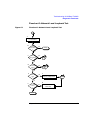
1
Using Dual Port 100Base-TX and Dual
Port Wide Ultra2 SCSI
Version B.11.00.01
Manufacturing Part Number:
E1099
U. S. A.
© Copyright 1999 Hewlett-Packard Company.
Legal Notices
The information in this document is subject to change without notice.
Hewlett-Packard makes no warranty of any kind with regard to this
manual, including, but not limited to, the implied warranties of
merchantability and fitness for a particular purpose. Hewlett-Packard
shall not be held liable for errors contained herein or direct, indirect,
special, incidental or consequential damages in connection with the
furnishing, performance, or use of this material.
Warranty. A copy of the specific warranty terms applicable to your
Hewlett- Packard product and replacement parts can be obtained from
your local Sales and Service Office.
Restricted Rights Legend. Use, duplication or disclosure by the U.S.
Government is subject to restrictions as set forth in subparagraph (c) (1)
(ii) of the Rights in Technical Data and Computer Software clause at
DFARS 252.227-7013 for DOD agencies, and subparagraphs (c) (1) and
(c) (2) of the Commercial Computer Software Restricted Rights clause at
FAR 52.227-19 for other agencies.
HEWLETT-PACKARD COMPANY
3000 Hanover Street
Palo Alto, California 94304
U.S.A.
Use of this manual and flexible disk(s) or tape cartridge(s) supplied for
this pack is restricted to this product only. Additional copies of the
programs may be made for security and back-up purposes only. Resale of
the programs in their present form or with alterations, is expressly
prohibited.
Copyright Notices. ©copyright 1999 Hewlett-Packard Company, all
rights reserved.
Reproduction, adaptation, or translation of this document without prior
written permission is prohibited, except as allowed under the copyright
laws.
2
Contents
1. Installing and Configuring PCI 10/100 Base-TX
Compatibility and Installation Requirements . . . . . . . . . . . . . . . . . . . . .10
Manual Speed and Duplex Mode Configuration . . . . . . . . . . . . . . . . . . .11
Autonegotiation and Autosensing. . . . . . . . . . . . . . . . . . . . . . . . . . . . . . .14
What Manuals are Available. . . . . . . . . . . . . . . . . . . . . . . . . . . . . . . . . . .15
Software Availability in Native Languages . . . . . . . . . . . . . . . . . . . . . . .16
2. Configuring Network Connectivity Using SAM
Step 1: Configuring Network Connectivity . . . . . . . . . . . . . . . . . . . . . . .19
Step 2: Deleting a Default Gateway . . . . . . . . . . . . . . . . . . . . . . . . . . . . .21
3. SCSI Parameter and Termination Information
Configuring SCSI Parameters. . . . . . . . . . . . . . . . . . . . . . . . . . . . . . . . . .24
SCSI Termination Information . . . . . . . . . . . . . . . . . . . . . . . . . . . . . . . . .25
4. Troubleshooting SCSI
Troubleshooting . . . . . . . . . . . . . . . . . . . . . . . . . . . . . . . . . . . . . . . . . . . . .28
5. 10/100Base-TX Resources
HP-UX Manual Reference Pages . . . . . . . . . . . . . . . . . . . . . . . . . . . . . . .46
Error Messages . . . . . . . . . . . . . . . . . . . . . . . . . . . . . . . . . . . . . . . . . . . . .48
Logging Messages . . . . . . . . . . . . . . . . . . . . . . . . . . . . . . . . . . . . . . . . . . .49
Manual Installation and Configuration . . . . . . . . . . . . . . . . . . . . . . . . . .51
Contacting Your HP Representative. . . . . . . . . . . . . . . . . . . . . . . . . . . . .52
iii
Contents
6. Troubleshooting 10/100Base-TX/9000
Performance Troubleshooting . . . . . . . . . . . . . . . . . . . . . . . . . . . . . . . . . 57
Corrective Action. . . . . . . . . . . . . . . . . . . . . . . . . . . . . . . . . . . . . . . . . . 58
Troubleshooting Overview . . . . . . . . . . . . . . . . . . . . . . . . . . . . . . . . . . . . 60
Diagnostic Flowcharts . . . . . . . . . . . . . . . . . . . . . . . . . . . . . . . . . . . . . . .
Flowchart 1: Network Level Loopback Test . . . . . . . . . . . . . . . . . . . .
Flowchart 2: 10/100Base-TX Connections/LED Test . . . . . . . . . . . . .
Flowchart 3: Configuration Test . . . . . . . . . . . . . . . . . . . . . . . . . . . . .
Flowchart 4: Configuration Test. . . . . . . . . . . . . . . . . . . . . . . . . . . . . .
Flowchart 4A: Configuration Test . . . . . . . . . . . . . . . . . . . . . . . . . . . .
Flowchart 5: Configuration Test . . . . . . . . . . . . . . . . . . . . . . . . . . . . .
Flowchart 6: Network Level Loopback Test . . . . . . . . . . . . . . . . . . . .
Flowchart 7: Link Level Loopback Test . . . . . . . . . . . . . . . . . . . . . . . .
Flowchart 8: Transport Level Loopback Test (using ARPA). . . . . . . .
Flowchart 9: Bridge/Gateway Loopback Test . . . . . . . . . . . . . . . . . . .
61
63
65
67
72
74
76
79
81
84
86
A. 10/100Base-TX Interface Card Statistics
LAN Interface Status Display . . . . . . . . . . . . . . . . . . . . . . . . . . . . . . . . . 90
RFC 1213 MIB II . . . . . . . . . . . . . . . . . . . . . . . . . . . . . . . . . . . . . . . . . . . 92
RFC 1284 Ethernet-Like Interface Statistics . . . . . . . . . . . . . . . . . . . . . 95
Create a Record or Map of Your Internetwork . . . . . . . . . . . . . . . . . . . . 97
B. Hardware Reference Information
Basic Troubleshooting Tips . . . . . . . . . . . . . . . . . . . . . . . . . . . . . . . . . . 100
Connector Information . . . . . . . . . . . . . . . . . . . . . . . . . . . . . . . . . . . . . .
PCI 10/100Base-TX Card Twisted-Pair Connector . . . . . . . . . . . . . .
Connector Pin Usage for 10-Mbit/s Twisted-Pair Connector . . . . . .
Connector Pin Usage for 100-Mbit/s Twisted-Pair Connector . . . . .
iv
101
101
101
102
Contents
Cabling Information . . . . . . . . . . . . . . . . . . . . . . . . . . . . . . . . . . . . . . . .104
Cable Lengths . . . . . . . . . . . . . . . . . . . . . . . . . . . . . . . . . . . . . . . . . . . .104
Dual Port 100Base-TX and Dual Port Wide
Ultra 2 SCSI Specifications. . . . . . . . . . . . . . . . . . . . . . . . . . . . . . . . . . .105
C. Hardware Regulatory Statements
FCC Statement (For U.S.A.) . . . . . . . . . . . . . . . . . . . . . . . . . . . . . . . . . .108
Canada . . . . . . . . . . . . . . . . . . . . . . . . . . . . . . . . . . . . . . . . . . . . . . . . . . .108
EMI Statement (European Community) . . . . . . . . . . . . . . . . . . . . . . . .109
Glossary . . . . . . . . . . . . . . . . . . . . . . . . . . . . . . . . . . . . . . . . . . . . . . . . 111
v
Contents
vi
Preface
The information in this manual is intended for network managers who
install and administer 10/100Base-TX networks and Wide Ultra2 SCSI
devices. It is assumed the reader is experienced with the basics of local
and wide area networking and SCSI technology.
This manual describes how to install, configure, and troubleshoot the 10/
100Base-TX and SCSI software and hardware product on HP 9000 PCI
systems.
The manual is organized as follows:
Chapter 1 , “Installing and Configuring PCI 10/100 Base-TX,” describes
how to install and configure 10/100Base-TX software and hardware. Also
it includes regulatory statements for the USA, Japan, and the European
community.
Chapter 2 , “Configuring Network Connectivity Using SAM,” describes
the steps to configure remote connectivity automatically using the
System Administration Manager (SAM).
Chapter 3, “SCSI Parameter and Termination Information” describes the
steps to configure remote connectivity automatically using the System
Administration Manager (SAM).
Chapter 4, “Troubleshooting SCSI” describes the steps to troubleshoot
the SCSI ports on the card.
Chapter 5 , “10/100Base-TX Resources,” provides references to other
useful tools for installing, configuring, and maintaining HP
10/100Base-TX software.
Chapter 6 , “Troubleshooting 10/100Base-TX/9000,”' provides flowcharts
to help diagnose 10/100Base-TX.
Appendix A , “10/100Base-TX Interface Card Statistics,” defines the
terms listed in the lanadmin(1M) command display.
Appendix B , “Hardware Reference Information,” provides information
about card specifications and cabling requirements.
7
8
1
Installing and Configuring PCI
10/100 Base-TX
This document contains information on the PCI 10/100Base-TX/9000
amd Wide Ultra2 SCSI cards for use with the 11.0 operating systems.
9
Installing and Configuring PCI 10/100 Base-TX
Compatibility and Installation Requirements
Compatibility and Installation Requirements
Following are the limits of the current PCI 10/100Base-TX/9000:
• The PCI 10/100Base-TX/9000 ports support autonegotiation and
autosensing. You should not normally need to manually configure the
speed, autonegotiation, or duplex mode of the card. If your switch does
not support autonegotiation but is set to full-duplex mode, there may
be a mismatch between the card and the switch, because the card
defaults to half-duplex for switches that do not support
autonegotiation. You can determine what the card is set to by using
lanadmin -x and reset it if necessary using lanadmin -X. See
“Manual Speed and Duplex Mode Configuration” for details.
If you manually set the speed and duplex mode of the Base-TX card,
autonegotiation will be turned off.
• Both full- and half-duplex modes are supported. If your hub or switch
does not support autonegotiation, ensure that your hub or switch is
set to the desired duplex mode.
• The PCI 0/100Base-TX/9000 LAN software is for use with only the
following protocols: TCP/IP, ARPA, and NFS.
• When using the ioscan -f command to verify installation, the last digit
of the H/W Path (hardware path) will show the port number of the
card. The other fields of the output will show the driver as btlan , and
the Hardware Type Description will be PCI.
10
Chapter 1
Installing and Configuring PCI 10/100 Base-TX
Manual Speed and Duplex Mode Configuration
Manual Speed and Duplex Mode
Configuration
Because the PCI 10/100Base-TX/9000 LAN ports support
autonegotiation, you should not normally need to manually set the
duplex mode. Sometimes you may need to manually set the duplex mode
of the card—for example, if the switch is operating at full-duplex but
does not autonegotiate. Because the card defaults to half-duplex when
autonegotiation is turned off, this could cause a mismatch between the
card and switch (at either 10 or100 Mbits/s). To fix this, use the
lanadmin -X command as described later in this section.
The CSMA/CD media access method used in IEEE 802.3u-1995 is
inherently a half-duplex mechanism. That is, at any one time, there can
be only one sender of data on the link segment. It is not possible for
devices on either end of the link segment to transmit simultaneously.
Since Category 5 UTP contains multiple pairs of wires, it is possible to
have devices on both ends of a link segment sending data to each other
simultaneously. This is known as full-duplex operation. While the details
of full-duplex operation are not currently defined by IEEE 802.3u-1995
(full-duplex mode essentially involves “turning off” the CSMA/CD access
method which is the foundation of IEEE 802.3), the autonegotiation
mechanism defined in IEEE 802.3u-1995 allows devices to advertise and
configure themselves to operate in a full-duplex mode which is
essentially vendor-specific. Devices that do not support autonegotiation
can sometimes be manually configured to operate in full-duplex mode.
Full-duplex mode is most commonly found in, and indeed only makes
sense for, switches rather than hubs. It may be found in either 10 Mbit/s
or 100 Mbit/s switch devices. Full-duplex mode may provide a
throughput advantage under some circumstances, but the degree of the
advantage is application-dependent.
The PCI 10/100Base-TX ports support both half- and full-duplex
operation.
Ensure that the speed, duplex mode, and autonegotiation of the
associated switch are configured the same as on the PCI 10/100Base-TX
card. If the switch supports autonegotiation on the ports connected to the
cards, this should be enabled as explained in “Autonegotiation and
Autosensing”.
Chapter 1
11
Installing and Configuring PCI 10/100 Base-TX
Manual Speed and Duplex Mode Configuration
To manually set the duplex mode of the PCI ports, first ensure that your
computer has the latest applicable patches installed as listed in the
Required and Optional Patches section of this release note.
To list the current speed and duplex mode of the PCI
10/100Base-TX/9000 ports, use the -x option (NOTE: lowercase x) of the
lanadmin command. Determine the speed and duplex mode of your hub
or switch before performing manual configuration as follows:
lanadmin -x ppa (HP-UX 11.0)
To manually set the duplex mode of the interface, install one of the
patches above and then use the -X option of lanadmin as follows:
lanadmin -X mode ppa (on HP-UX 11.0)
where:
mode can be any one of the following strings (and the fd or hd are
case-insensitive):
10fd =10 full-duplex
10hd =10 half-duplex
100fd =100 full-duplex
100hd =100 half-duplex
and
lanadmin -X auto_on ppa (turns autonegotiation on for HP-UX 11.0)
The ppa is the physical point of attachment on HP-UX 11.0. You can get
the ppa from the output of the lanscan command.
Example:
If the ppa of the 100Base-TX interface is 5, the command to set the card
to 10Mbits/s and full-duplex mode would be:
lanadmin -X 10fd 5
After issuing the lanadmin -X, you must wait at least 11 seconds before
attempting to use the specified network interface.
If you want the Duplex Mode setting to be effective in all subsequent
reboots, you must enter the information in the following file:
/etc/rc.config.d/hpbtlanconf
Manually configuring the speed or duplex setting of a switch port on
12
Chapter 1
Installing and Configuring PCI 10/100 Base-TX
Manual Speed and Duplex Mode Configuration
some switches may disable that switch port from doing autonegotiation.
Verify that both the card and the switch port are operating in the same
speed and duplex mode as desired.
If you use manual configuration to change the card to a different speed
and duplex mode, you may need to turn autonegotiation on first before
the manual setting takes place.
NOTE
Mismatches between the speed, autonegotiation, or duplex mode of the
card and switch will cause incorrect operation.
Chapter 1
13
Installing and Configuring PCI 10/100 Base-TX
Autonegotiation and Autosensing
Autonegotiation and Autosensing
Autonegotiation is a mechanism defined in the IEEE 802.3u specification
whereby devices sharing a link segment can exchange information and
automatically configure themselves to operate at the highest capability
mode shared between them.
Autonegotiation is like a rotary switch that automatically switches to the
correct technology such as 10Base-T or 100Base-TX or between half- and
full-duplex modes. Once the highest performance common mode is
determined, auto-negotiation passes control of the link to the
appropriate technology, sets the appropriate duplex mode, and then
becomes transparent until the link is broken.
Following is the IEEE 802.3u-defined hierarchy for resolving multiple
common abilities for a 10/100Base-TX card. The PCI
10/100Base-TX/9000 ports provide the means for interfacing various
types of HP 9000 workstations and servers to either a 10Base-T or
100Base-TX network. 100Base-TX is a subset of 100Base-T networking
defined by the IEEE 802.3u-1995 standard. 100Base-TX provides 100
Mbit/s data transmission over category 5 unshielded twisted-par (UTP)
cable. Two pairs of wires in the cable are used—one wire pair is for
receiving data, and one wire pair is for transmitting data. The same card
port that supports 100Base-TX operation can also support 10Base-T
operation.
• 100Base-TX full-duplex
• 100Base-TX half-duplex
• 10Base-T full-duplex
• 10Base-T half-duplex
For example, if both devices on the link support 10Base-T (half-duplex)
and 100Base-TX (half-duplex), autonegotiation at both ends will connect
the 100Base-TX (half-duplex) instead of the 10Base-T (half-duplex).
Most Fast Ethernet devices on the market today such as hubs and
switches do not support autonegotiation. Either the speed and duplex
mode of the device are fixed (as is usually the case with hubs), or they are
often manually configured at the desired speed and duplex (as is often
the case for switches). However, switches that support autonegotiation
are starting to be offered.
14
Chapter 1
Installing and Configuring PCI 10/100 Base-TX
What Manuals are Available
If a PCI 10/100Base-TX/9000 port is connected to a device, such as a
switch, that is autonegotiating, the PCI card will autonegotiate with the
device to mutually determine the highest possible speed and duplex
settings between them.
NOTE
If a PCI 10/100Base-TX/9000 port is connected to a device that does not
support autonegotiation or a device that has autonegotiation disabled, the
PCI port will autosense the speed of the link and set itself accordingly.
The duplex mode of the card will be set to half-duplex in this
case. If you want the card to operate in full-duplex mode, you have to set
it using the method described in Manual Speed and Duplex Mode
Configuration.
The PCI 10/100Base-TX port will sense when the connection between
itself and a hub or switch on the other end of a link has been broken. If a
connection is made to another (or the same) device, the autonegotiation
and autosensing process will be done again automatically.
Autonegotiation and autosensing are also done whenever the interface is
reset.
What Manuals are Available
The following documents summarize installation, configuration,
verification and troubleshooting of the Dual Port 100Base-TX and Dual
Port Wide Ultra2 SCSI card:
Dual Port 100Bas-TX and Dual Port Wide Ultra2 SCSI Quick
Installation
Chapter 1
15
Installing and Configuring PCI 10/100 Base-TX
Software Availability in Native Languages
Software Availability in Native Languages
The commands used with this product are the ones supported by the
Native Language Support Catalog of HP-UX.
16
Chapter 1
2
Configuring Network
Connectivity Using SAM
This chapter describes how to configure remote connectivity using SAM.
It contains the following sections:
17
Configuring Network Connectivity Using SAM
• Step 1: Configuring Network Connectivity
• Step 2: Deleting a Default Gateway (Optional)
18
Chapter 2
Configuring Network Connectivity Using SAM
Step 1: Configuring Network Connectivity
Step 1: Configuring Network Connectivity
Your system may not be able to communicate with other systems, for
example, PCs, workstations, servers, etc., until you configure
system-to-system connections by adding an entry in hosts for the remote
system. You can use SAM to do this automatically by completing the
following steps:
1. At the HP-UX prompt, type: sam
2. Double click Networking and Communications at the SAM main
window.
3. Double click Internet Addresses to enable your system to
communicate with other systems using the TCP/IP protocol.
SAM displays the remote system names and Internet addresses that
are already configured.
4. Choose Add from the “Actions” menu to open the Add Internet
Address window to add the internet address and system name of a
remote system.
Use the SAM online help system for information about adding remote
system connections.
a. Enter the Internet address for the remote system.
Upon exiting the Internet Address field, SAM checks to make
sure you have entered a valid IP/Internet address. SAM also
determines if a gateway is required for the connection (see step
4c).
b. Enter the remote system name.
Upon exiting the Remote System Name field, SAM checks to make
sure that connectivity has not already been configured for this
system. If it has, SAM displays an error message.
c. Optionally, choose Add Aliases to open the Add Aliases window if
you want to configure aliases for a remote system.
You can modify or remove alias names for a remote system on this
menu
Activate the OK button to perform the task and return to the Add
Chapter 2
19
Configuring Network Connectivity Using SAM
Step 1: Configuring Network Connectivity
Internet Addresses window.
Proceed to step 5 if a gateway is not required for this remote
connection.
SAM displays fields for entering gateway information if a gateway
is required for this remote system connection. Use the SAM online
help system for information about gateways.
5. Activate the OK button to enable your system to communicate with
this system and return to the System-to-System Connectivity object
list.
SAM updates the object list to include the remote system you
configured.
NOTE
You can modify or remove remote systems and modify default gateways
by highlighting the Remote System Name from the object list and
choosing Modify, Remove, or Modify Default Gateway from the “Actions”
menu.
6. Choose Exit from the “File” menu.
7. At the Networking Communications window, choose Exit SAM from
the “File” menu to leave SAM.
8. Verify remote system configuration.
a. View the list of remote systems you can communicate with using a
symbolic name by typing the following command at the HP-UX
prompt:
more /etc/hosts
b. View the configured destinations reached through gateways and
the gateways used to reach those destinations by typing the
following command at the HP-UX prompt:
netstat -r
To verify that you can communicate with a remote system via the
10/100Base-TX product, return to chapter 1, “Step 8: Verify the
Installation.”
20
Chapter 2
Configuring Network Connectivity Using SAM
Step 2: Deleting a Default Gateway
Step 2: Deleting a Default Gateway
To delete a default gateway that you have added with SAM, do the
following:
1. Enter the following command at the HP-UX prompt:
route
delete
default
gateway_hostname
where gateway_hostname is the hostname of the default gateway you
want to delete.
2. Edit the /etc/rc.config.d/netconf file to remove the corresponding
internet routing configuration parameter values for the gateway. For
example:
ROUTE_DESTINATION [0] = ROUTE_GATEWAY [0] =
ROUTE_COUNT [0] =
Chapter 2
21
Configuring Network Connectivity Using SAM
Step 2: Deleting a Default Gateway
22
Chapter 2
3
SCSI Parameter and
Termination Information
23
SCSI Parameter and Termination Information
Configuring SCSI Parameters
Configuring SCSI Parameters
In order to change the SCSI ID, the path for the card of interest must
first be determined. Once the path is known, the SCSI ID may be
changed. The example below lists the commands used to determine the
path for the card of interest, change the SCSI ID of the A5838A, and also
some of the other parameters of the card.
The machine should be booted to the BCH prompt before beginning this
procedure.
The path for the A5838A SCSI card is determined as follows:
- at the Main Menu, type "in" (for information menu)
- at the Information Menu, type "io" (to display I/O interface information)
The information displayed should be similar to the following:
PCI DEVICE INFORMATION
Path
Description
-----------
Vendor Device Bus Slot
(dec)
-----
Id
----
Id
#
#
---- --- ---
.
.
SCSI bus cntlr
0/2/0/0
0x1000 0xb
16 6
.
.
.
The path for the card in this example is '0/2/0/0'.
Once the path for the card is known:
- type "main" (to return to main menu)
- type "ser" (to display service menu)
- type "scsi" (to display current status of SCSI devices)
The information displayed should be similar to the following:
24
Chapter 3
SCSI Parameter and Termination Information
SCSI Termination Information
Path (dec)
Initiator ID
SCSI Rate
------------ -------------- ----------
Auto Term
---------------
.
.
0/2/0/0
7
Fast
ON
.
.
.
The SCSI bus speed (rate) can be changed as follows:
- if at the Main Menu, type "ser" (to display service menu)
- type "scsi rate <path> <speed>"
(where <path> is the path obtained as shown above, and <speed> is 'fast'
or 'ultra')
The SCSI ID of the controller card can be changed as follows:
- if at the Main Menu, type "ser" (to display service menu)
- type "scsi init <path> <new ID>"
(where <path> is the path obtained as shown above, and
<new ID> is a single digit, 0 - 7)
SCSI Termination Information
The A5838A card is shipped from the factory with autotermination
enabled. If the A5838A is placed at the end of a SCSI bus,
autotermination is enabled, so there is no need for external terminators.
If the A5838A card is installed in the middle of a SCSI bus, you must
change its SCSI ID and disable autotermination for the port by placing a
jumper across two-pins on the card. Refer to the Quick Installation
Guide for details.
Chapter 3
25
SCSI Parameter and Termination Information
SCSI Termination Information
26
Chapter 3
4
Troubleshooting SCSI
27
Troubleshooting SCSI
Troubleshooting
Troubleshooting
The A5838A host bus adapter is a single field-replaceable unit (FRU) and does not
contain any field-serviceable parts. Troubleshooting procedures described in this
section are limited to verifying that the controller is operational and a valid
connection is established.
General Procedure
1.
Check the connection.
Make sure that the correct cable is used, connected, and operating properly and
that there are no bent pins in any of the connectors.
2.
Check SCSI bus compatibility.
Ensure transfer rate compatibility with the attached devices using the SCSI boot
menu command.
3.
Check the controller.
Inspect the controller to make sure it is seated properly in the PCI bus slot. If
necessary, power down the system, reseat the controller, and restart the system.
4.
Run diagnostics.
If a visual inspection of the controller and cable does not reveal any problems,
or if an action taken as a result of the inspection does not produce a working
controller, you may want to run diagnostics to determine whether the controller
can communicate and respond to PCI bus instructions. Diagnostics are
described in the next section.
28
Chapter 4
Troubleshooting SCSI
Troubleshooting
If diagnostics determine that the controller is defective, you must replace it. Contact
your local Hewlett-Packard customer representative or call the HP Response Center.
SCSI Bus Compatibility
Use the SCSI command to ensure SCSI controller and SCSI device compatibility by
displaying and selecting SCSI bus parameters.
The SCSI command is available from the boot menu displayed after the test station
has booted, provided autoboot is disabled.
Command
Description
----------------AUto [BOot|SEArch ON|OFF]
Display or set the specified flag
BOot [PRI|ALT|<path> <args>]
Boot from a specified path
BootTimer [time]
Display or set boot delay time
CLEARPIM
Clear PIM storage
CPUconfig [<proc>] [ON|OFF]
Configure/Deconfigure Processor
DEfault
Set the sytem to defined values
DIsplay
Display this menu
ForthMode
Switch to the Forth OBP interface
IO
List the I/O devices in the system
LS [<path>|flash]
List the boot or flash volume
OS [hpux|sppux]
Display/Select Operating System
PASSword
Set the Forth password
PAth [PRI|ALT|CON] [<path>]
Display or modify a path
PDT [CLEAR|DEBUG]
Display/clear Non-Volatile PDT state
PIM_info [cpu#] [HPMC|TOC|LPMC] Display PIM of current or any CPU
RESET [hard|debug]
Force a reset of the system
RESTrict [ON|OFF]
Display/Select restricted access
toForth
SCSI [INIT|RATE] [bus slot val] List/Set SCSI controller parms
SEArch [<path>]
Search for boot devices
SECure [ON|OFF]
Display or set secure boot mode
TIme [cn:yr:mo:dy:hr:mn[:ss]]
Display or set the real-time clock
VErsion
Display the firmware versions
Command:
Figure 1
Chapter 4
Boot Menu
29
Troubleshooting SCSI
Troubleshooting
SCSI Command
Use the SCSI command to ensure SCSI controller and SCSI device compatibility by
displaying and selecting SCSI bus parameters.
The SCSI command is available from the boot menu displayed after the test station
has booted, provided autoboot is disabled.
The SCSI parameters can be displayed and modified using the SCSI command. The
syntax for this command is:
SCSI rate bus# slot# rate
SCSI init bus# slot# id#
bus#
The bus number
slot#
The adapter’s slot number
rate
The adapter’s transfer rate
0: no limit
10: Fast SCSI
20: Ultra SCSI
id#
The SCSI ID number of the adapter
Display and Set SCSI Transfer Rates
1.
Display the SCSI transfer rate for an adapter using the SCSI command.
The following example lists the SCSI transfer rate for an adapter on bus 5 slot
2:
command: SCSI rate 5 2
PCI device /5.2 = no limit
Enter the command without specifying a bus or slot number to list transfer rates
for all bus and slot numbers:
command: SCSI rate
2.
Set the SCSI transfer rate for an adapter using the SCSI command.
The following example sets the adapter on bus 5 slot 2 to Fast SCSI and then
displays the results:
command: SCSI rate 5 2 10
30
Chapter 4
Troubleshooting SCSI
Troubleshooting
command: SCSI rate 5 2
PCI device /5.2 = fast scsi
Display and Set SCSI IDs
1.
Display the initiator (SCSI) IDs for all controllers, buses, and slots using the
SCSI command.
The following example shows the SCSI ID for the controller on bus 5 slot 2.
SCSI init 5 2
PCI device /5.2 = 7
Enter the command without specifying a bus or slot number to list initiator IDs
for all bus and slot numbers:
SCSI init
2.
Set the initiator (SCSI) ID of an adapter using the SCSI command.
The following example sets bus 5 slot 2 to initiator ID 6 and displays the
results:
SCSI init 5 2 6
SCSI init 5 2
PCI device /5.2 = 6
Chapter 4
31
Troubleshooting SCSI
Troubleshooting
Contacting Your HP Representative
If the equipment is covered by an HP service contract, document the problem as a
service request and forward it to your HP representative. Include the following
information where applicable:
•
Describe the problem, including the events and symptoms leading up to the
problem. Attempt to describe the source of the problem.
Include HP-UX commands, communication subsystem commands,
functionality of user programs, result codes and messages, and data that can
reproduce the problem.
•
Obtain the version, update, and fix information for all software. To check the
version of the kernel, enter this command:
uname -r
To check patches, enter:
what /stand/vmunix | grep scsi
This allows HP to determine if the problem is already known and the correct
software is installed at your site.
•
Illustrate as clearly as possible the context of any messages. Record all error
messages and numbers that appear at the user terminal and the system console.
•
Prepare the formatted output and a copy of the log file for the HP representative
to analyze.
•
Prepare a listing of the HP-UX I/O configuration being used for the HP
representative to analyze.
•
Try to determine the general area within the software where the problem may
exist. Refer to the appropriate reference manual and follow the guidelines on
gathering information for that product.
•
Document your interim (workaround) solution. The cause of the problem can
sometimes be found by comparing the circumstances in which the problem
occurs with the circumstances in which the problem does not occur.
32
Chapter 4
Troubleshooting SCSI
Troubleshooting
•
In the event of a system failure, obtain a full memory dump. If the directory
/var/adm/crash exists, the HP-UX utility /sbin/savecore automatically executes
during reboot to save the memory dump. HP recommends that you create the
/tmp/syscore directory after successfully installing this product. Send the output
of the system failure memory dump to the HP representative.
Chapter 4
33
Troubleshooting SCSI
Troubleshooting
If the equipment is not covered by an HP service contract, there may be a charge for
time and materials.
SCSI Sense Codes
The following example shows a typical SCSI error message.
[+6708 72410001 002a9858 0:7] scsi disk: CHECK CONDITION on
disk 0:6:5:0
Read of logical block 509856, count 128
disk sd45a, block 254920, 65536 bytes
Valid = 1, Error code = 0x70
Segment number = 0x00, Filemark = 0, EOM = 0, ILI = 0
Sense key = 0x1, "RECOVERED ERROR"
Information = 0x00 0x07 0xc7 0xe4
[+6709 72410001 002a9a10 0:7] scsi disk:
Additional sense
length = 0x0a
Command-specific information = 0x00 0x00 0x00 0x00
Additional sense = 0x18, Qualifier = 0x01
Field replaceable unit code = 0xea
SKSV = 1, C/D = 0, BPV = 0, Bit pointer = 0
Field pointer = 0x0003
The status (CHECK CONDITION) and sense key (RECOVERED ERROR) are
interpreted. The Additional sense and Qualifier codes require interpretation. Use
both codes to locate the interpretation. In the example, the Additional sense (0x18)
and Qualifier (0x01) codes are interpreted as “recovered data with error correction
and retries applied.” and list all possible status and sense key codes. interprets the
Additional sense and Qualifier codes contained in SCSI error messages reported by
the console.
34
Chapter 4
Troubleshooting SCSI
Troubleshooting
SCSI Status Codes
SCSI Status
Code
Name
0x00
good
0x02
check condition
0x04
condition met
0x08
busy
0x10
intermediate
0x14
intermediate - condition met
0x18
reservation conflict
0x22
command terminated
0x28
queue full
SCSI Sense Keys
Sense Key
Name
0
no sense
0x1
recovered error
0x2
not ready
0x3
medium error
0x4
hardware error
0x5
illegal request
0x6
unit attention
0x7
data protect
0x8
blank check
0x9
vendor-specific
0xa
copy aborted
0xb
aborted command
0xc
equal
Chapter 4
35
Troubleshooting SCSI
Troubleshooting
SCSI Sense Keys (Continued)
Sense Key
Name
0xd
volume overflow
0xe
miscompare
0xf
reserved
SCSI Additional Sense and Qualifier Codes
Additional
Sense Code
Qualifier
Code
Description
0x00
0x00
no additional sense information
0x00
0x01
filemark detected
0x00
0x02
end-of-partition/medium detected
0x00
0x03
setmark detected
0x00
0x04
beginning of partition/medium detected
0x00
0x05
end-of-data detected
0x00
0x06
i/o process terminated
0x00
0x11
audio play operation in progress
0x00
0x12
audio play operation paused
0x00
0x13
audio play operation successfully completed
0x00
0x14
audio play operation stopped due to error
0x00
0x15
no current audio status to return
0x01
0x00
no index/sector signal
0x02
0x00
no seek complete
0x03
0x00
peripheral device write fault
0x03
0x01
no write current
0x03
0x02
excessive write errors
0x04
0x00
logical unit not ready, cause not reportable
0x04
0x01
logical unit in process of becoming ready
0x04
0x02
logical unit not ready, initializing command required
0x04
0x03
logical unit not ready, manual intervention required
36
Chapter 4
Troubleshooting SCSI
Troubleshooting
SCSI Additional Sense and Qualifier Codes (Continued)
Additional
Sense Code
Qualifier
Code
Description
0x04
0x04
logical unit not ready, format in progress
0x05
0x00
logical unit does not respond to selection
0x06
0x00
reference position found
0x07
0x00
multiple peripheral devices selected
0x08
0x00
logical unit communication failure
0x08
0x01
logical unit communication time-out
0x08
0x02
logical unit communication parity error
0x09
0x00
track following error
0x09
0x01
tracking servo failure
0x09
0x02
focus servo failure
0x09
0x03
spindle servo failure
0x0a
0x00
error log overflow
0x0c
0x00
write error
0x0c
0x01
write error recovered with auto reallocation
0x0c
0x02
write error - auto reallocation failed
0x10
0x00
id crc or ecc error
0x11
0x00
unrecovered read error
0x11
0x01
read retries exhausted
0x11
0x02
error too long to correct
0x11
0x03
multiple read errors
0x11
0x04
unrecovered read error - auto reallocate failed
0x11
0x05
l-ec uncorrectable error
0x11
0x06
circ unrecovered error
0x11
0x07
data resynchronization error
0x11
0x08
incomplete block read
0x11
0x09
no gap found
0x11
0x0a
miscorrected error
0x11
0x0b
unrecovered read error - recommend reassignment
0x11
0x0c
unrecovered read error - recommend rewrite the data
Chapter 4
37
Troubleshooting SCSI
Troubleshooting
SCSI Additional Sense and Qualifier Codes (Continued)
Additional
Sense Code
Qualifier
Code
Description
0x12
0x00
address mark not found for id field
0x13
0x00
address mark not found for data field
0x14
0x00
recorded entity not found
0x14
0x01
record not found
0x14
0x02
filemark or setmark not found
0x14
0x03
end-of-data not found
0x14
0x04
block sequence error
0x15
0x00
random positioning error
0x15
0x01
mechanical positioning error
0x15
0x02
positioning error detected by read of medium
0x16
0x00
data synchronization mark error
0x17
0x00
recovered data with no error correction applied
0x17
0x01
recovered data with retries
0x17
0x02
recovered data with positive head offset
0x17
0x03
recovered data with negative head offset
0x17
0x04
recovered data with retries and/or circ applied
0x17
0x05
recovered data using previous sector id
0x17
0x06
recovered data without ecc - data auto-reallocated
0x17
0x07
recovered data without ecc - recommend reassignment
0x17
0x08
recovered data without ecc - recommend rewrite
0x18
0x00
recovered data with error correction applied
0x18
0x01
recovered data with error correction and retries applied
0x18
0x02
recovered data - data auto-reallocated
0x18
0x03
recovered data with circ
0x18
0x04
recovered data with lec
0x18
0x05
recovered data - recommend reassignment
0x18
0x06
recovered data - recommend rewrite
0x19
0x00
defect list error
0x19
0x01
defect list not available
38
Chapter 4
Troubleshooting SCSI
Troubleshooting
SCSI Additional Sense and Qualifier Codes (Continued)
Additional
Sense Code
Qualifier
Code
Description
0x19
0x02
defect list error in primary list
0x19
0x03
defect list error in grown list
0x1a
0x00
parameter list length error
0x1b
0x00
synchronous data transfer error
0x1c
0x00
defect list not found
0x1c
0x01
primary defect list not found
0x1c
0x02
grown defect list not found
0x1d
0x00
miscompare during verify operation
0x1e
0x00
recovered id with ecc
0x20
0x00
invalid command operation code
0x21
0x00
logical block address out of range
0x21
0x01
invalid element address
0x22
0x00
illegal function
0x24
0x00
invalid field in cdb
0x25
0x00
logical unit not supported
0x26
0x00
invalid field in parameter list
0x26
0x01
parameter not supported
0x26
0x02
parameter value invalid
0x26
0x03
threshold parameters not supported
0x27
0x00
write protected
0x28
0x00
not ready to ready transition (medium may have changed)
0x28
0x01
import or export element accessed
0x29
0x00
power on, reset, or bus device reset occurred
0x2a
0x00
parameters changed
0x2a
0x01
mode parameters changed
0x2a
0x02
log parameters changed
0x2b
0x00
copy cannot execute since host cannot disconnect
0x2c
0x00
command sequence error
0x2c
0x01
too many windows specified
Chapter 4
39
Troubleshooting SCSI
Troubleshooting
SCSI Additional Sense and Qualifier Codes (Continued)
Additional
Sense Code
Qualifier
Code
Description
0x2f
0x00
commands cleared by another initiator
0x30
0x00
incompatible medium installed
0x30
0x01
cannot read medium - unknown format
0x30
0x02
cannot read medium - incompatible format
0x30
0x03
cleaning cartridge installed
0x31
0x00
medium format corrupted
0x32
0x00
no defect spare location available
0x32
0x01
defect list update failure
0x33
0x00
tape length error
0x36
0x00
ribbon, ink, or tower failure
0x37
0x00
rounded parameter
0x39
0x00
saving parameters not supported
0x3a
0x00
medium not present
0x3b
0x00
sequential positioning error
0x3b
0x01
tape position error at beginning-of-medium
0x3b
0x02
tape position error at end-of-medium
0x3b
0x03
tape or electronic vertical forms unit not ready
0x3b
0x04
slew failure
0x3b
0x05
paper jam
0x3b
0x06
failed to sense top-of-form
0x3b
0x07
failed to sense bottom-of-form
0x3b
0x08
reposition error
0x3b
0x09
read past end of medium
0x3b
0x0a
read past beginning of medium
0x3b
0x0b
position past end of medium
0x3b
0x0c
position past beginning of medium
0x3b
0x0d
medium destination element full
0x3b
0x0e
medium source element empty
0x3d
0x00
invalid bits in identify message
40
Chapter 4
Troubleshooting SCSI
Troubleshooting
SCSI Additional Sense and Qualifier Codes (Continued)
Additional
Sense Code
Qualifier
Code
Description
0x3e
0x00
logical unit has not self-configured yet
0x3f
0x00
target operating conditions have changed
0x3f
0x01
microcode has been changed
0x3f
0x02
changed operating definition
0x3f
0x03
inquiry data has changed
0x40
0x00
ram failure
0x40
nn
diagnostic failure on component nn
0x41
0x00
data path failure
0x42
0x00
power-on or self-test failure
0x43
0x00
message error
0x44
0x00
internal target failure
0x45
0x00
select or reselect failure
0x46
0x00
unsuccessful soft reset
0x47
0x00
scsi parity error
0x48
0x00
initiator detected error message received
0x49
0x00
invalid message error
0x4a
0x00
command phase error
0x4b
0x00
data phase error
0x4c
0x00
logical unit failed self-configuration
0x4e
0x00
overlapped commands attempted
0x50
0x00
write append error
0x50
0x01
write append position error
0x50
0x02
position error related to timing
0x51
0x00
erase failure
0x52
0x00
cartridge fault
0x53
0x00
media load or eject failed
0x53
0x01
unload tape failure
0x53
0x02
medium removal prevented
0x54
0x00
scsi to host system interface failure
Chapter 4
41
Troubleshooting SCSI
Troubleshooting
SCSI Additional Sense and Qualifier Codes (Continued)
Additional
Sense Code
Qualifier
Code
Description
0x55
0x00
system resource failure
0x56
0x00
reserved
0x57
0x00
unable to recover table of contents
0x58
0x00
generation does not exist
0x59
0x00
updated block read
0x5A
0x00
operator request or state change input (unspecified)
0x5A
0x01
operator medium removal request
0x5A
0x02
operator selected write protect
0x5A
0x030
operator selected write permit
0x5B
0x00
log exception
0x5B
0x01
threshold condition met
0x5B
0x02
log counter at maximum
0x5B
0x03
log list codes exhausted
0x5C
0x00
rpl status change
0x5C
0x01
spindles synchronized
0x5C
0x02
spindles not synchronized
0x5D
0x00
reserved
0x5E
0x00
reserved
0x5F
0x00
reserved
0x60
0x00
lamp failure
0x61
0x00
video acquisition error
0x61
0x01
unable to acquire video
0x61
0x02
out of focus
0x62
0x00
scan head positioning error
0x63
0x00
end of user area encountered on this track
0x64
0x00
illegal mode for this track
0x65
0x00
reserved
0x66
0x00
reserved
0x67
0x00
reserved
42
Chapter 4
Troubleshooting SCSI
Troubleshooting
SCSI Additional Sense and Qualifier Codes (Continued)
Additional
Sense Code
Qualifier
Code
Description
0x68
0x00
reserved
0x69
0x00
reserved
0x6A
0x00
reserved
0x6B
0x00
reserved
0x6C
0x00
reserved
0x6D
0x00
reserved
0x6E
0x00
reserved
0x6F
0x00
reserved
Chapter 4
43
Troubleshooting SCSI
Troubleshooting
44
Chapter 4
5
10/100Base-TX Resources
In addition to this manual, use the following resources to maintain and
administer PCI 10/100Base-TX/9000.
45
10/100Base-TX Resources
HP-UX Manual Reference Pages
HP-UX Manual Reference Pages
While installing, configuring, or troubleshooting 10/100Base-TX, you
may need to refer to any of the following online manual reference pages
(man pages) for useful HP-UX operating system or 10/100Base-TX
commands. To display a man page, type the following at the system
prompt: man <command name>. For example, man arp.
• arp(1M) displays and modifies the Internet-to-station address
mapping tables used by the Address Resolution Protocol.
• hosts(4) is a database that contains a single line entry for each host
name entry.
• ifconfig(1M) assigns an address to a network interface, and configures
and displays network parameters.
• ioscan(1M) scans system hardware, usable I/O system devices, or
kernel I/O system data structures as appropriate, and lists the
results.
• lanadmin(1M) resets or reports the status of the LAN card.
• lanconfig(1M) sets/resets the packet encapsulation method for a
network interface.
• lanscan(1M) displays information about LAN cards that are
successfully bound to the system.
• linkloop(1M) verifies network connectivity through the Data Link
Layer (OSI Layer 2).
• netfmt(1M) formats common tracing and logging binary files.
• netstat(1) provides network statistics and information about network
connections.
• nettl(1M) logs network events and traces packets as they enter and
exit the 10/100Base-TX driver.
• ping(1M) verifies network connectivity through the Network Layer
(OSI Layer 3) and reports the round-trip time of communications
between the local and remote hosts.
• route(1M) adds and deletes entries to the network routing table.
• sam(1M) configures networking software.
46
Chapter 5
10/100Base-TX Resources
HP-UX Manual Reference Pages
• swinstall(1M) loads software filesets onto 10.x systems.
• swverify(1M) verifies software installation.
Chapter 5
47
10/100Base-TX Resources
Error Messages
Error Messages
PCI 10/100Base-TX comes with an online message catalog that is used to
report networking problems. You must use the nettl logging and tracing
utility to display the probable cause and action for a message.
48
Chapter 5
10/100Base-TX Resources
Logging Messages
Logging Messages
HP 100Base-TX/9000 uses the nettl(1M) logging and tracing facility
supplied with HP-UX. You may access the logging and tracing utility
using either the graphical user interface (GUI) version or the command
line interface.
Features of the GUI version, which are now a part of your HP 9000
system, include:
• An interface which guides you through logging and tracing tasks.
• An interface which allows you to create and format reports.
• The capability to collect logging and tracing subsystem-specific
information.
• Report screens which are updated instantaneously with current
logging and tracing information by the subsystem.
• Context-sensitive on-line help.
To access the GUI version of the logging and tracing utility, run the
command:
nettladm
See the nettladm(1M) man page for information on using the GUI
version, or the nettl(1M) manual (man) page for information on using the
command line interface.
Listed below are some example commands using the command line
interface.
• To examine the log file with cause and action descriptions.
netfmt
-v
-f /var/adm/nettl.LOG00 | more
The -v option enables the reporting of available cause and action
descriptions for each log message. A sample 10/100Base-TX log
message using the -v option is shown below.
******100 Mb/s LAN/9000 Networking**********************
Fri May 16 PDT 1997 15:08:07.091398 DISASTER
Subsys:LAN100 Loc:00000
Chapter 5
49
10/100Base-TX Resources
Logging Messages
<6011> HP PCI 10/100Base-T driver detected bad cable
connection between the adapter in slot 2 and the hub
or switch.
• To examine just the log messages in the log file.
netfmt
-f /var/adm/nettl.LOG00
• To check network logging and tracing status.
nettl
-status
• To start 10/100Base-TX tracing to the file /tmp/tracefile.TRC0.
nettl(1m) adds the .TRC0 postfix for you.
nettl -traceon all
/tmp/tracefile
-entity PCI100bt
-file
• To stop 100Base-TX tracing.
nettl
-traceoff
-entity PCI100bt
• To format the 10/100Base-TX trace file into the file /tmp/traceout.
netfmt
-f /tmp/tracefile.TRC0
>
/tmp/traceout
Refer to the netfmt(1M) man page for further information about this card
and how to create a filter for trace formatting.
50
Chapter 5
10/100Base-TX Resources
Manual Installation and Configuration
Manual Installation and Configuration
If you want to manually install and configure your 10/100Base-TX/9000
product, refer to the detailed instructions in the Installing and
Administering LAN/9000 Software manual.
You may need some of the following 10/100Base-TX/9000-specific
information when you follow those steps:
• HP 9000 PCI driver keyword: btlan
• The driver for the PCI 10/100Base-TX card has a floating major
number (that is, a major number assigned dynamically by the
operating system).
Chapter 5
51
10/100Base-TX Resources
Contacting Your HP Representative
Contacting Your HP Representative
If you have no service contract with HP, you may follow the procedure
described below, but you will be billed accordingly for time and materials.
If you have a service contract with HP, document the problem as a
Service Request (SR) and forward it to your HP representative. Include
the following information where applicable:
• A characterization of the problem. Describe the events leading up to
and including the problem. Attempt to describe the source and
symptoms of the problem.
Your characterization should include: HP-UX commands;
communication subsystem commands; job streams; result codes and
messages; and data that can reproduce the problem. You should also
provide a network map with the host name, IP/Internet address, and
station address of each system connected with the HP system.
Illustrate as clearly as possible the context of any message(s).
Prepare copies of information displayed at the system console and
user terminal.
• Obtain the version, update, and fix information for all software. To
check the 10/100Base-TX version number, execute what vmunix and
look for the keyword, vtlan1.
To check the version of your kernel, execute uname -r.
This allows HP to determine if the problem is already known and if
the correct software is installed at your site.
• Prepare copies of the /etc/hosts, and /etc/rc.config.d/netconf files.
• Execute the dmesg command and record messages about the status of
the 10/100Base-TX card.
• Execute the lanscan -v command and record the output.
• Execute the display command of the lanadmin diagnostic on the
10/100Base-TX interface and record the output.
• Record the troubleshooting flowchart number and step number where
you are unable to resolve the problem.
• Record all error messages and numbers that appear at the user
terminal and the system console.
52
Chapter 5
10/100Base-TX Resources
Contacting Your HP Representative
• Save all network log files. Make sure that ERROR and DISASTER log
classes are enabled when log files are collected.
Prepare the formatted output and a copy of the log file for your HP
representative to further analyze.
• Prepare a listing of the HP-UX I/O configuration you are using for
your HP representative to further analyze. Use the ioscan(1M)
command to help collect this information
• Try to determine the general area within the software where you
think the problem exists. Refer to the appropriate reference manual
and follow the guidelines on gathering information for that product.
• Document your interim, or “workaround,” solution. The cause of the
problem can sometimes be found by comparing the circumstances in
which it occurs with the circumstances in which it does not occur.
• Create copies of any Internet or 10/100Base-TX/9000 link trace files
that were active when the problem occurred for your HP
representative to further analyze.
• In the event of a system failure, a full memory dump must be
taken. Use the HP-UX utility savecore(1M) to save a core dump.
Send the output to your HP representative.
Chapter 5
53
10/100Base-TX Resources
Contacting Your HP Representative
54
Chapter 5
6
Troubleshooting
10/100Base-TX/9000
This chapter provides guidelines for troubleshooting 10/100Base-TX. It
contains the following sections:
55
Troubleshooting 10/100Base-TX/9000
• Troubleshooting Overview.
• Diagnostic Flowcharts.
56
Chapter 6
Troubleshooting 10/100Base-TX/9000
Performance Troubleshooting
Performance Troubleshooting
This section is intended to provide system administrators or
advanced users with detailed information on how to troubleshoot
performance related problems with the PCI 100BT product.
Below, a few key terms are defined to help in understanding the
troubleshooting information.
Key Terms:
Transmit Threshold:
The transmit threshold value determines how many bytes must be in the
PCI 100BT transmit FIFO before transmission of the bits onto the
ethernet cable will begin.
Transmit Underrun:
A transmit underrun error occurs when the PCI 100BT transmitter
encounters an empty transmit FIFO during the transmission of bits onto
the ethernet cable.
Memory Subsystem Latency:
The memory subsystem latency is defined to be the amount of time it
takes to move data from system memory to an I/O device. This time
includes the arbitration delay for the I/O device and for each bus bridge
between the system memory controller and the I/O device.
Arbitration Delay:
The time it takes an I/O device, or bus bridge to acquire the I/O bus for
data transfer.
Transmit FIFO:
The transmit FIFO is a buffer on the PCI 100BT card used to hold data
transferred from system memory to the PCI 100BT card.
The PCI 100BT product is currently optimized to achieve the best single
card performance. In order to achieve this performance the PCI 100BT
product has set the Transmit Threshold to an aggressive value. The
Transmit Threshold is set so that transmission will begin after 512 bytes
Chapter 6
57
Troubleshooting 10/100Base-TX/9000
Performance Troubleshooting
are in the transmit FIFO.
While the current Transmit Threshold value allows the PCI 100BT
product to achieve it's best performance, it also increases the probability
of Transmit Underrun errors. A large number of Transmit Underrun
errors (more than 1 out of every 1000 packets) can cause a noticeable
drop in networking performance.Transmit Underrun errors may occur
when there is sufficient bus contention from competing I/O devices.
These errors can be monitored in two ways:
1. Examine the output from the netstat -I interface command. If
the number of output errors is high (more than 1 out of every X
packets) then the system is most likely suffering from transmit
underruns on the specified network interface and corrective action
must be taken to resolve the problem.
2. Turn on nettl errors and warnings for the network interface being
monitored. The following command will turn on disasters, errors and
warnings for the network interface with Instance number 1. (NOTE:
It is highly recommended to always keep disasters and errors
enabled).
nettl -log 0xe -e PCI100bt -C 1
The nettl log file (by default is called /var/adm/nettl.LOG00) should then
be monitored for the following message:
HPPCI 10/100Base-T driver encountered a Transmit Underflow
If a significant number of these messages occur, and the timestamps for
each of the messages are within 30 seconds of each other, then the
specified networking interface will suffer a noticeable performance drop.
Corrective action must be taken to resolve this problem.
Corrective Action
The PCI 100BT product supports 3 levels of Transmit Threshold. These
3 levels are modified via the -S option of the lanadmin command as
follows:
lanadmin -S TransmitThreshold nmid
where:
a TransmitThreshold of 1024 is somewhat aggressive
a TransmitThreshold of 512 is most aggressive
58
Chapter 6
Troubleshooting 10/100Base-TX/9000
Performance Troubleshooting
a TransmitThreshold of 1500 is conservative
In all of the cases above after setting the Transmit Threshold mode as
specified, the lanadmin command will echo the current speed of the
interface as follows; this output may be ignored (output shown for 100
Mbits/s operation):
old speed= 100000000
new speed= 100000000
After issuing the lanadmin -S you must wait at least 5 seconds before
attempting to use the specified network interface.
If the desired Transmit Threshold setting needs to be effective in all
subsequent reboots, you must create an SD script and include it in the
/sbin/init.d directory so that it gets executed on each reboot.
Chapter 6
59
Troubleshooting 10/100Base-TX/9000
Troubleshooting Overview
Troubleshooting Overview
10/100Base-TX problems can be caused by problems in a variety of
hardware and software components. The problem impacting your system
may originate in another part of the 10/100Base-TX network.
As with any troubleshooting, a systematic approach is helpful. The
following two tables and the following flowcharts provide a logical
sequence of steps to follow when troubleshooting 10/100Base-TX/9000.
Using the diagnostic flowcharts provided in this chapter, identify
whether the problem is with 10/100Base-TX/9000 or any of the
connections to the hub or switch, or whether it is in some other part of
the network, verify your assumptions and, if it is limited to
10/100Base-TX/9000 software or hardware, correct the problem.
NOTE
To quickly isolate and diagnose 10/100Base-TX/9000 problems, follow the
steps in the troubleshooting flowcharts, beginning with Flowchart 1, and
stay with the flowcharts until the problems are resolved. Continue
sequentially through flowcharts 2, 3, 4, 5, 6, and 7, referring back to
flowchart 1 (ping) until you have corrected the problems.
If you cannot solve the problem on your own, contact your HP
representative. Use the guidelines at the end of chapter 3 to help you
effectively communicate what is wrong. The 10/100Base-TX product uses
diagnostic tools compatible with the HP LAN/9000 Link product.
60
Chapter 6
Troubleshooting 10/100Base-TX/9000
Diagnostic Flowcharts
Diagnostic Flowcharts
Below is a summary of the types of network tests in the diagnostic
flowcharts. Follow the flowcharts in sequence beginning with flowchart 1.
Continue sequentially through flowcharts 2, 3, 4, 5, 6, 7, 8, and 9,
referring back to flowchart 1 (ping), as indicated at the end of each
flowchart, until you have corrected the problem.
Table 6-1
Flowchart Descriptions
Flowchart
Description
1
Network Level Loopback Test
2
10/100Base-TX Connections/LED Test
3, 4, and 5
Configuration Test
6
Network Level Loopback Test
7
Link Level Loopback Test
8
Transport Level Loopback Test (using ARPA)
9
Bridge/Gateway Loopback Test
Network Level Loopback Test: Checks roundtrip communication
between Network Layers on the source and target host using the
ping(1M) command.
10/100Base-TX Connections/LED Test: Checks that all the hardware
connections between your system and the 10/100Base-TX network are
connected and operational.
Configuration Test: Verifies the configuration of the network interface
on a host using the lanscan(1M), netfmt -vf, lanadmin(1M), and
ifconfig(1M) commands.
Network Level Loopback Test (cont): Checks arp entries using the
arp(1M) command.
Link Level Loopback Test: Checks roundtrip communication between
Link Levels on the source and target host using the linkloop(1M)
diagnostic.
Chapter 6
61
Troubleshooting 10/100Base-TX/9000
Diagnostic Flowcharts
Transport Level Loopback Test: Checks roundtrip communication
between Transport Layers on the source and target host using ARPA
services telnet and ftp commands.
Bridge/Gateway Loopback Test: Checks general network connections
through a gateway.
62
Chapter 6
Troubleshooting 10/100Base-TX/9000
Diagnostic Flowcharts
Flowchart 1: Network Level Loopback Test
Figure 6-1
Flowchart 1: Network Level Loopback Test
1
A
Execute: ping
to remote host
B
ping
successful
?
yes
Stop
no
C
Network
unreachable
?
yes
3
no
D
Command
hangs
?
yes
2,3,4,5
6&7
no
E
F
Unknown
host
?
yes
Correct BIND, YP or
/etc/hosts configuration
1
no
H
G
No route
to host
?
yes
Add route
table entry
no
Call HP
Chapter 6
63
Troubleshooting 10/100Base-TX/9000
Diagnostic Flowcharts
Flowchart 1 Procedures
A.
Execute: ping to remote host. Using ping(1M), send
a message to the remote host to which you are having
problems connecting. For example:
ping spiff
B.
ping successful? A message is printed to stdout for
each ping packet returned by the remote host. If
packets are being returned, your system has network
level connectivity to the remote host. Note what
percentage of the total packets are lost, if any. Losing
ten percent or more may indicate the network or
remote host is extremely busy. You may also find it
useful to note the round-trip transmission times.
Periodically high transmission times may indicate that
the network or remote host is extremely busy.
Consistently high transmission times may indicate the
local host is extremely busy. If a message is not
returned after executing ping, ping is not successful.
Do Cntrl C to stop the ping output.
C.
Network unreachable? If yes, go to flowchart 3 to
display connection status using the lanscan(1M)
command.
D.
Command hangs. If a message is not returned after
executing ping, go to flowcharts 2 through 7, referring
back to flowchart 1 (ping) until you have corrected the
problem.
E.
Unknown host? If you receive this message, go to step
F.
F.
Correct BIND, YP or hosts configuration. Add the
missing host name and start again with flowchart 1.
G.
No route to host? If Error= Sendto: No route to
host, go to Step H. Otherwise, call your HP
representative for help.
H.
Add route table entry. Using route, add a route table
entry for that host. Refer to the route(1M) online man
page for more details. Start again with flowchart 1.
64
Chapter 6
Troubleshooting 10/100Base-TX/9000
Diagnostic Flowcharts
Flowchart 2: 10/100Base-TX Connections/LED Test
Figure 6-2
Flowchart 2: 10/100Base-TX Connections/LED Test
2
C
A
Check:
Power outlet
LED Display:
B
100
Mbit
LED=ON
Test
Errorport
Message
10onMbit
port
LED=OFF
Screen
(dmesg
ouput)
Check card installation.
yes
Reset card. Call HP if
problem persists.
?
no
1
D
Check status of
Link LED
F
E
yes
Link LED = OFF
?
Check connection to hub
or switch. Ensure switch
is autonegotiating.
Ensure hub/switch is
10Base-T or 100Base-TX.
Reset card.
no
1
H
LED Display:
G
100
port LED=ON
DoMbit
link speed
and duplex
10mode
Mbitmatch
port switch
LED=OFF
?
no
Set attached hub or switch
to correct speed, duplex mode,
and autonegotiation.
Reset card.
yes
3
Chapter 6
1
65
Troubleshooting 10/100Base-TX/9000
Diagnostic Flowcharts
Flowchart 2 Procedures
A.
Check Power outlet. Ensure the power cord is
plugged in to a live outlet.
B.
Test Error Message on Screen? At the HP-UX
prompt, type the dmesg command, and look for
an error message. Does the dmesg output show
an error message from btlan? If not, go to step D.
Note: even if the Test LED is OFF, a card problem is
still possible if either of the following two messages
appear:
btlan: Error: Motherboard failed to complete
reset.
btlan: Error: Motherboard failed selftest;error
code= 0x?
C.
Check card installation. If dmesg reported an
error message from btlan, reset card according
to Steps D through G in Flowchart 4. If problem
persists, call HP. Go back to flowchart 1.
D.
Check status of Link LED.
E.
Link LED = OFF? If it is off, proceed to step F.
If Link LED = ON, proceed to step G.
F.
If Link LED = OFF, check connection to hub or switch.
Ensure switch is not autonegotiating. Ensure hub or
switch is 10Base-T or 100Base-TX. Reset card
according to Steps D through G in Flowchart 4. Go
back to flowchart 1.
G.
Do link speed and duplex mode match switch? If
they do, proceed to flowchart 3.
H.
If Link speed and duplex mode do not match
what you expect, set attached hub or switch to
the correct link speed and duplex mode, and
enable autonegotiation. Reset card according to
Steps D through G in Flowchart 4. Go back to
flowchart 1.
66
Chapter 6
Troubleshooting 10/100Base-TX/9000
Diagnostic Flowcharts
Flowchart 3: Configuration Test
Figure 6-3
Flowchart 3: Configuration Test
3
A
Execute: lanscan
B
D
Is
your interface
displayed
?
yes
C
no
Run ioscan -f
E
Is driver in
kernel
?
yes
no F
G
yes
5
Install driver.
Verify or edit
/stand/system
to add driver keyword
btlan
Regen kernel.
H
Reboot the
system
Check
hardware
I
Hardware
up
?
no
Problem
fixed
?
yes
no
1
Stop
Chapter 6
67
Troubleshooting 10/100Base-TX/9000
Diagnostic Flowcharts
Flowchart 3 Procedures
NOTE
Check that your 10/100Base-TX connectors to the card and hub (or wall
plug) are fully connected before beginning this flowchart.
A.
Execute: lanscan. Enter the lanscan command to
display information about LAN cards that are
successfully bound to the system. See the lanscan
online manpage for more detailed information.
B.
Is your interface displayed? lanscan shows
information about every LAN card in the system
backplane. The Hardware Path of one of the entries
should correspond to the PCI 10/100Base-TX card slot
multiplied times 4. For example, a hardware path of 32
corresponds to an PCI 10/100Base-TX card in slot 8.
C.
Hardware up.The hardware state is operational if up is
displayed for the 10/100Base-TX card under the
Hardware State heading. If it is, continue to flowchart
5. If not, go to D.
D.
Run ioscan. ioscan will scan the system hardware
and list the results. If you execute ioscan -f, output
68
Chapter 6
Troubleshooting 10/100Base-TX/9000
Diagnostic Flowcharts
similar to the following will be displayed:
Chapter 6
69
Troubleshooting 10/100Base-TX/9000
Diagnostic Flowcharts
Class
I
H/W Path
Driver
S/W State H/W Type
Description
========================================================================
bc
0
root
CLAIMED
BUS_NEXUS
bc
1
8
ccio
CLAIMED
BUS_NEXUS I/O Adapter
bc
2
10
ccio
CLAIMED
BUS_NEXUS I/O Adapter
ext_bus
0
10/0
c720
CLAIMED
INTERFACE GSC built-in
Fast/Wide SCSI Interface
bc
3
10/4
bc
CLAIMED
BUS_NEXUS Bus Converter
tty
0
10/4/0
mux2
CLAIMED
INTERFACE MUX
lanmux
2
10/4/4
lanmux0
CLAIMED
INTERFACE HP J2146A - 802.3 LAN
lan
1
10/4/4.1
lan3
CLAIMED
INTERFACE
ba
0
10/8
GSCtoPCI
CLAIMED
BUS_NEXUS PCI Bus Bridge
lan
2
10/8/1/0
btlan CLAIMED
PCI (10110009)
lan
3
10/8/2/0
btlan CLAIMED
PCI (10110009)
ba
1
10/12
bus_adapter CLAIMED
BUS_NEXUS Core I/O Adapter
ext_bus
2
10/12/0
CentIf
CLAIMED
INTERFACE Built-in Parallel
Interface
ext_bus
1
10/12/5
c720
CLAIMED
INTERFACE Built-in SCSI
target
3
10/12/5.2
tgt
CLAIMED
DEVICE
disk
XM-5401TA
2
10/12/5.2.0
sdisk
CLAIMED
DEVICE
target
3
10/12/5.7
tgt
CLAIMED
DEVICE
ct1
1
10/12/5.7.0
sct1
CLAIMED
DEVICE
lan
0
10/12/6
lan2
CLAIMED
INTERFACE Built-in LAN
ps2
0
10/12/7
ps2
CLAIMED
TOSHIBA CD-ROM
Initiator
INTERFACE Built-in Keyboard/Mous
processor
0
32
processor
CLAIMED
PROCESSOR Processor
processor
1
34
processor
CLAIMED
PROCESSOR Processor
memory
0
49
memory
CLAIMED
MEMORY
70
Chapter 6
Memory
Troubleshooting 10/100Base-TX/9000
Diagnostic Flowcharts
E.
Is driver in kernel? If the driver has not been
generated into the kernel, ioscan output will be:
ioscan -f
Class
I
Description
H/W Path
Driver
S/W State H/W Type
===============================================================
====
unknown
-1 10/4/4
UNKNOWN
UNCLAIMED INTERFACE
The class and driver fields alone will indicate
“unknown” status if the kernel has not been generated.
If the driver has not been generated, continue to step
H. If the driver is in the kernel, go to step G.
F.
Verify or edit /stand/system and regen kernel.
Verify/edit /stand/system contains the btlan keyword.
If not, see “Creating a New Kernel” in chapter 3 of the
Installing and Administering LAN/9000 Software
manual for instructions on how to edit /stand/system
to create a new kernel.
G.
Check hardware. Verify that the network card is
seated correctly and that it is operational.
H.
Reboot the system.
I.
Problem fixed? If you have found the 10/100Base-TX
card problem, stop. If not, start again with flowchart 1.
Chapter 6
71
Troubleshooting 10/100Base-TX/9000
Diagnostic Flowcharts
Flowchart 4: Configuration Test
Figure 6-4
Flowchart 4: Configuration Test
4
A
Execute: netfmt
B
Check causes and
actions on display
in the formatted log
output
C
Problem
solved
?
yes
1
no
D
Execute: lanadmin
E
Select LAN from
Menu
F
Select NMID command
and enter 10/100
Base-TX nmid
G
Reset card
H
Reset
successful
yes
1
?
no
4A
72
Chapter 6
Troubleshooting 10/100Base-TX/9000
Diagnostic Flowcharts
Flowchart 4 Procedures
A.
Execute: netfmt. Use the netfmt command to view log
data (error and disaster messages). An example
command is shown below.
netfmt -v -f /var/adm/nettl.LOG00 | more
B.
Check causes and actions on display in the
formatted log output. Use the time stamp to find the
proper logs. Ensure that you are looking at the
10/100Base-TX information.
C.
Problem solved. If yes, go to flowchart 1. If not,
continue with step D.
D.
Execute lanadmin. Run lanadmin(1M). For a
complete description of this command, refer to the
lanadmin(1M) on-line manual page.
E.
Select LAN from Menu. Select lan from the menu to
enter LAN Interface Diagnostic.
F.
Select the NMID command and enter the
10/100Base-TX NMID. You can use the lanscan
command to find the current NMID for 10/100Base-TX.
The NMID you enter becomes the current device to be
tested.
G.
Reset the card according to Steps D through G in
Flowchart 4. Using the reset command in lanadmin
re-executes the LAN card self-test.
H.
Reset successful? The reset is successful if no errors
are displayed as a result of the reset command. If the
self-test was successful, the problem may be that you
are not connected to the 10/100Base-TX network.
Correct the problem and verify the resolution by
continuing with flowchart 1. Otherwise, go to flowchart
4A.
Chapter 6
73
Troubleshooting 10/100Base-TX/9000
Diagnostic Flowcharts
Flowchart 4A: Configuration Test
Figure 6-5
Flowchart 4A: Configuration Test
4A
A
Execute: netfmt
B
Check causes and
actions on display
in the formatted log
output
C
Problem
solved
yes
1
?
no
Call HP
Flowchart 4A Procedures
A.
Execute: netfmt. Use the netfmt command to view log
data (error and disaster messages). An example netfmt
command is shown below:
netfmt -v -f /var/adm/nettl.LOG00 | more
Extend the search to LOG01 as information may have
rolled (overflowed) into this file from LOG00.
B.
Check causes and actions on display in the
formatted log output. Use the time stamp to find the
proper logs. Ensure that you are looking at the
74
Chapter 6
Troubleshooting 10/100Base-TX/9000
Diagnostic Flowcharts
10/100Base-TX information.
C.
Chapter 6
Problem solved. If yes, go to flowchart 1. If not,
contact your HP representative.
75
Troubleshooting 10/100Base-TX/9000
Diagnostic Flowcharts
Flowchart 5: Configuration Test
Figure 6-6
Flowchart 5: Configuration Test
5
A
Execute
ifconfig <interface>
...<IP address> up
B
Execute:
ifconfig <interface>
E
C
ifconfig
successful
?
D
no
Are
flags correct
?
yes
H
Correct ifconfig
flag settings
5
yes
ifconfig
entry in
/etc/rc.config.d/netconf
:
?
yes
F
Any error
messages
returned
no
Call HP
?
yes
no
I
no
G
Add ifconfig
command to
/etc/rc.config.d/netconf
Correct problem
according to the
message received
1
5
Flowchart 5 Procedures
A.
76
Execute: ifconfig <interface> <IP address> up.
Chapter 6
Troubleshooting 10/100Base-TX/9000
Diagnostic Flowcharts
Execute ifconfig on the interface you want to configure
in order to ensure that the interface is enabled. For
example, to configure the 10/100Base-TX interface
lan1, enter:
ifconfig lan1 192.6.1.17 up
For more examples of the ifconfig command, refer to
the ifconfig(1M) online man page.
B.
Execute: ifconfig <interface>. Execute ifconfig
without the up parameter again on the interface you
want to test to check the flag setting for the up
parameter. For example, to check the 10/100Base-TX
interface lan1, enter:
ifconfig lan1
C.
ifconfig successful? ifconfig is successful if the
output shows the correct Internet address and the
flags: <UP,BROADCAST, NOTRAILERS, RUNNING>.
Note: Make sure the UP flag is displayed.
D.
Are flags correct? If flags are not correct, use the
ifconfig command to correct them. If they are correct,
go to step F.
E.
Correct ifconfig flag settings. If ifconfig returns an
incorrect flag setting, re-execute the command with the
proper setting. For more information, refer to the
ifconfig(1M) online man page. Start again with
flowchart 5, as necessary.
F.
Any error message returned? If ifconfig is not
successful, and an error message appears, go to Step G.
If no error messages appear, contact your HP
representative.
G.
Correct problem according to the message
received. If you received an error message, make the
appropriate corrections stated in the message and then
begin this procedure again.
H.
ifconfig entry in /etc/rc.config.d/netconf? Check
that there is an entry in the /etc/rc.config.d/netconf
file for your 10/100Base-TX card.
Chapter 6
77
Troubleshooting 10/100Base-TX/9000
Diagnostic Flowcharts
I.
78
Add ifconfig command to /etc/rc.config.d/netconf
file. Add the ifconfig command to
/etc/rc.config.d/netconf, and reboot. For more
information, refer to the ifconfig(1M) online man page.
Go to flowchart 1 to verify that the problem has been
solved.
Chapter 6
Troubleshooting 10/100Base-TX/9000
Diagnostic Flowcharts
Flowchart 6: Network Level Loopback Test
Figure 6-7
Flowchart 6: Network Level Loopback Test
6
A
Host entry
in ARP
cache
?
B
no
Remote
host up
?
yes
1
no
yes
C
Bring up
remote host
1
E
D
Entry
complete
?
no
Use arp to
complete entry
yes
F
ping local host
1
Chapter 6
79
Troubleshooting 10/100Base-TX/9000
Diagnostic Flowcharts
Flowchart 6 Procedures
A.
Host entry in ARP cache? Using arp, check that an
entry exists for the remote host in your system's ARP
cache. For example:
arp spiff
B.
Remote host up? If there is no ARP cache entry for
the remote host, first check that the remote host is up.
If not, the remote host has not broadcast an ARP
message, and that probably is why there is no entry in
the ARP cache.
C.
Bring-up remote host. Have the node manager of the
remote host bring that system up and start again with
flowchart 1.
D.
Entry complete? Perhaps there is an ARP cache
entry, but it is wrong or not complete. If the entry is
complete, go to step F.
E.
Use arp to complete entry. Using arp, enter the
correct Station Address. For more information, refer to
the arp(1M) online man page. Start again with
flowchart 1.
F.
ping local host. Using ping, do an internal loopback
on your own system. In other words, ping your own
system.
If the internal loopback is successful, your system is
operating properly to the Network Layer (OSI Layer 3).
In addition, you know an ARP cache entry for the
remote host exists on your system. Start again with
Flowchart 1.
80
Chapter 6
Troubleshooting 10/100Base-TX/9000
Diagnostic Flowcharts
Flowchart 7: Link Level Loopback Test
Figure 6-8
Flowchart 7: Link Level Loopback Test
7
A
Execute: linkloop
to remote host
B
yes
linkloop
successful
?
1
no
D
C
Loopback FAILED:
Address has bad
format
E
Loopback FAILED:
Not an individual
address
F
Loopback
FAILED
G
Choose a different
remote host;
re-execute
linkloop
Correct the link
address parameter
7
H
6
no
linkloop
successful
?
yes
I
Check remote host’s
connectivity to
100Base-TX
1
Chapter 6
81
Troubleshooting 10/100Base-TX/9000
Diagnostic Flowcharts
Flowchart 7 Procedures
A.
Execute: linkloop to remote host. Enter the NMID
of your 10/100Base-TX card and link level address
(station address) of the remote host in hexadecimal
form (preceded by “0x”). Execute lanscan (1M) on the
local system to find the NMID and obtain the link level
address (station address) of the remote host. For more
information on linkloop, refer to the linkloop(1M)
online man page.
B.
linkloop successful? If the test was successful, go to
flowchart 1 to verify that the problem is solved.
Network connectivity is o.k. through the Link Layer
(OSI Layer 2). If not successful, note which error was
returned and continue with this flowchart.
C.
Loopback failed: Address has bad format. The
link level address is not correct. Go to F.
D.
Loopback failed: Not an individual address. The
link level address is not correct. The first hexadecimal
digit has its high order bit set (if the value is equal to or
greater than 8, it is set). This means it is a multicast or
broadcast address, which is not allowed. The address
must be unique to one remote host. Go to F.
E.
Loopback failed. The remote host did not respond.
Go to G.
F.
Correct the link address parameter. Change the
link level address to an allowed value and start again
with flowchart 7.
G.
Choose a different remote host; re-execute
linkloop. Restart flowchart 7 using a different remote
host.
H.
linkloop successful? If the test was successful, go to
step I. Network connectivity is o.k. through the Link
Layer (OSI Layer 2). If not successful, the problem may
be with the remote system. Go to flowchart 6.
I.
Check remote host's connectivity to
10/100Base-TX. Contact the node manager of the
remote host. Check that the host is configured correctly
and that its network interface is up. If necessary, use
82
Chapter 6
Troubleshooting 10/100Base-TX/9000
Diagnostic Flowcharts
flowchart 1 to verify configuration of the remote host.
Chapter 6
83
Troubleshooting 10/100Base-TX/9000
Diagnostic Flowcharts
Flowchart 8: Transport Level Loopback Test (using
ARPA)
Figure 6-9
Flowchart 8: Transport Level Loopback Test (using ARPA)
8
A
Execute: telnet to
remote host
B
Successful
?
yes
Stop
no
C
Execute: ftp to
remote host
D
Successful
?
yes
Call HP
no
E
TCP
not configured
on local or
remote
host
?
G
yes
Configure
TCP
8
no
F
Network
congested
?
no
yes
Call HP
Call HP
84
Chapter 6
Troubleshooting 10/100Base-TX/9000
Diagnostic Flowcharts
Flowchart 8 Procedures
A.
Execute: telnet to remote host. Try to establish a
telnet connection to the remote host.
B.
Successful? If your telnet attempt was successful,
stop. The connection is o.k. through the Transport
Layer (OSI Layer 4).
C.
Execute: ftp to remote host. Unlike telnet, ftp does
not go through a pseudoterminal driver (pty) on your
system. This step tests to see if the pty is why telnet
failed.
D.
Successful? If ftp is successful, you likely have a
problem with a pty on your system. Contact your HP
representative.
E.
TCP not configured on local nor remote host?
Neither telnet or ftp will work if TCP is not configured
on either side of the connection. Check the
/etc/protocols file on both hosts to be sure TCP is
installed and configured.
F.
Network congested? If TCP is installed on both
hosts, do a file transfer to another remote host on the
network. Use netstat(1) to check for lost packets.
If network congestion is not the cause, more detailed
diagnostics are required. Again, contact your HP
representative.
G.
Chapter 6
Configure TCP. If necessary, install TCP on either or
both hosts. Start again with this flowchart.
85
Troubleshooting 10/100Base-TX/9000
Diagnostic Flowcharts
Flowchart 9: Bridge/Gateway Loopback Test
Figure 6-10
Flowchart 9: Bridge and Gateway Loopback Test
9
A
Execute: ping from
known good host
through gateway to
known good host
C
B
yes
Check route table
on problem host and
all hosts between
Successful
?
D
no
E
Examine
gateway
Correct route
tables
1
F
G
Non-HP 9000 or
other vendors.
Refer to networking
documentation
If HP 9000
execute: ifconfig
on gateway host
H
Network
interface up
?
yes
3
no
I
Configure interface
up
1
86
Chapter 6
Troubleshooting 10/100Base-TX/9000
Diagnostic Flowcharts
Flowchart 9 Procedures
A.
Execute: ping from known good host through
gateway to known good remote host. This will test
gateway connectivity to the remote network.
B.
Successful? If the executing ping returned
successfully, the problem may exist in the routing table
for the problem host. Go to C.
C.
Check route table on problem host and all hosts
in between. Execute netstat -r to examine a route
table.
D.
Examine gateway. If the gateway is an HP 9000, go
to G. If it is not, go to F.
E.
Correct route tables. Ensure that the proper
IP/Internet addresses are assigned in the Destination
and Gateway fields. If you are using subnetting, make
sure that the destination is what you expect: a network
or a host. Go to flowchart 1 to verify that the problem is
solved.
F.
Non-HP 9000 or other vendors. Refer to
networking documentation. Refer to the
documentation that came with the gateway for
additional diagnostics.
G.
If HP 9000, execute ifconfig on gateway host.
Execute ifconfig for all network interfaces on the
gateway.
H.
Network interface up? If the output from ifconfig
does not include the UP parameter, the network
interface is down. Execute netstat -i to check the status
of the network interfaces. An asterisk (*) indicates that
the interface is down. If the network interface is down,
go to I.
If the network interfaces are UP, start again with
flowchart 3. Using flowchart 3, test all network
interfaces on the gateway.
I.
Chapter 6
Configure interface up. Execute ifconfig on each
interface to bring it up. Start again with flowchart 1.
Using flowchart 1, test all network interfaces on the
87
Troubleshooting 10/100Base-TX/9000
Diagnostic Flowcharts
gateway.
88
Chapter 6
A
10/100Base-TX Interface Card
Statistics
89
10/100Base-TX Interface Card Statistics
LAN Interface Status Display
LAN Interface Status Display
This appendix contains descriptions of the RFC 1213 MIB II statistics
fields for LAN interface cards which are displayed on the screen with the
display command in lanadmin LAN Interface Test Mode. A description
of each field follows the display.
LAN INTERFACE STATUS DISPLAY
Tue, Nov 30,1999 11:45:17
Network Management ID
Description
Type (value)
MTU Size
Speed
Station Address
Administration Status (value)
Operation Status (value)
Last Change
Inbound Octets
Inbound Unicast Packets
Inbound Non-Unicast Packets
Inbound Discards
Inbound Errors
Inbound Unknown Protocols
Outbound Octets
Outbound Unicast Packets
Outbound Non-Unicast Packets
Outbound Discards
Outbound Errors
Outbound Queue Length
Specific
= 5
= btlan Hewlett-Packard
10/100Base-TX Full-Duplex
Hw Rev 0
= ethernet-csmacd(6)
= 1500
= 100000000
= 0x80009d40d69
= up(1)
= down(2)
= 0
= 0
= 0
= 0
= 0
= 0
= 0
= 0
= 0
= 0
= 0
= 0
= 0
= 655367
Ethernet-like Statistics Group
Index
Alignment Errors
FCS Errors
Single Collision Frames
Multiple Collision Frames
90
=
=
=
=
=
3
0
0
0
0
Appendix A
10/100Base-TX Interface Card Statistics
LAN Interface Status Display
Deferred Transmissions
Late Collisions
Excessive Collisions
Internal MAC Transmit Errors
Carrier Sense Errors
Frames Too Long
Internal MAC Receive Errors
Appendix A
=
=
=
=
=
=
0
0
0
0
0
0
= 0
91
10/100Base-TX Interface Card Statistics
RFC 1213 MIB II
RFC 1213 MIB II
For more detailed information about the fields described below, refer to
RFC 1213.
Field
Description
Network Management ID A unique ID assigned by the system for the
network management of each network interface.
Description
A textual string containing information about the
interface.
Type (value)
The type of interface, distinguished according to the
physical/link protocols, immediately below the network
layer in the protocol stack.
10/100Base-TX can have one of the following values:
ethernet-csmacd(6), or iso88023-csmacd(7).
The following values are for other networking products.
MTU Size
The size of the largest datagram which can be
sent/received on the interface specified in octets. This
value is 1500.
Speed in bits per second The speed of the 10/100Base-TX card, 10 Mbit/s
or 100 Mbit/s.
Station Address The interface address at the protocol layer immediately
below the network layer in the protocol stack. For
interfaces which do not have such an address, such as
serial line, this object contains an octet string of zero
length.
Administration Status The desired state of the interface. This
parameter is set to up(1) and is not configurable. It
will have one of the following values:
92
up(1)
Ready to pass packets
down(2)
Not operative
testing(3)
In test mode
Appendix A
10/100Base-TX Interface Card Statistics
RFC 1213 MIB II
Operation Status The current operational state of the interface. This
value is the same as the hardware status displayed by
lanscan(1M). It will have one of the following values.
Last Change
up(1)
Ready to pass packets
down(2)
Not operative (card is down)
testing(3)
In test mode
The value of SysUpTime at the time the interface
entered its current operational state. If the current
state was entered prior to the last reinitialization of the
local network management subsystem, then this object
contains a zero value.
Inbound Octets The total number of octets received on the interface,
including framing characters.
Inbound Unicast Packets The number of subnetwork-unicast packets
delivered to a high-layer protocol.
Inbound Non-Unicast Packets The number of non-unicast
(subnetwork-broadcast or subnetwork-multicast)
packets delivered to a higher-layer protocol.
Inbound Discards The number of inbound packets that were discarded
even though no errors had been detected, to prevent
their being delivered to a higher-layer protocol. One
possible reason for discarding such a packet could be to
free up buffer space.
Inbound Errors The number of inbound packets that contained errors
preventing them from being deliverable to a
higher-layer protocol.
Inbound Unknown Protocols The number of packets received via the
interface which were discarded because of an unknown
or unsupported protocol.
Outbound Octets The total number of octets transmitted out of the
interface, including framing characters.
Outbound Unicast Packets The total number of packets that
higher-level protocols requested be transmitted to a
subnetwork-unicast address, including those that were
discarded or not sent.
Appendix A
93
10/100Base-TX Interface Card Statistics
RFC 1213 MIB II
Outbound Non-Unicast Packets The total number of packets that
higher-level protocols requested be transmitted to a
non-unicast (a subnetwork-broadcast or
subnetwork-multicast) address, including those that
were discarded or not sent.
Outbound Discards The number of outbound packets that were
discarded even though no errors had been detected to
prevent their being transmitted. One possible reason
for discarding such a packet could be to free up buffer
space.
Outbound Errors The number of outbound packets that could not be
transmitted because of errors.
Outbound Queue Length The length of the output packet queue (in
packets).
94
Appendix A
10/100Base-TX Interface Card Statistics
RFC 1284 Ethernet-Like Interface Statistics
RFC 1284 Ethernet-Like Interface Statistics
Field
Description
Index
A value that uniquely identifies an interface to an
802.3 medium.
Alignment Errors A count of frames received on a particular interface
that are not an integral number of octets in length and
do not pass the FCS check.
FCS Errors
A count of frames received on a particular interface
that are not an integral number of octets in length and
do not pass the FCS check.
Single Collision Frames A count of successfully transmitted frames on a
particular interface for which transmission is inhibited
by exactly one collision.
Multiple Collision Frames A count of successfully transmitted frames on
a particular interface for which transmission is
inhibited by more than one collision.
Deferred Transmissions A count of frames for which the first
transmission attempt on a particular interface is
delayed because the medium is busy. The count
represented by an instance of this object does not
include frames involved in collisions.
Late Collisions
The number of times that a collision is detected on a
particular interface later than 512 bit-times into the
transmission of a packet.
Excessive Collisions A couple of frames for which transmission on a
particular interface fails due to excessive collisions in
10-Base-T mode. For 100Base-TX mode, excessive
collisions indicate the number of packets dropped.
Internal MAC Transmit Errors A count of frames for which
transmission on a particular interface fails due to an
internal MAC sublayer transmit error.
Carrier Sense Errors The number of times that the carrier sense
Appendix A
95
10/100Base-TX Interface Card Statistics
RFC 1284 Ethernet-Like Interface Statistics
condition was lost or never asserted when attempting
to transmit a frame on a particular interface.
Frames Too Long A count of frames received on a particular interface
that exceed the maximum permitted framer size.
Internal MAC Receive Errors A count of frames for which reception on a
particular interface fails due to an internal MAC
sublayer receive error.
96
Appendix A
10/100Base-TX Interface Card Statistics
Create a Record or Map of Your Internetwork
Create a Record or Map of Your Internetwork
Be sure to create or update a record of your network and internetwork
before attempting 10/100Base-TX installation. You may wish to create a
map showing how pieces of your internetwork are related. Your records
should include:
• Approximate dimensions of the building or room containing the
10/100Base-TX network.
• Location of, routers, bridges, and gateways
• Location of nodes and node connections.
• Location of network segments and subnets within each segment
• Hostname of each node.
• Internet Address and Alias of each node (in the case of gateways, each
10/100Base-TX card has its own Internet Address and Alias).
• Hardware Path of each card in the system including 10/100Base-TX
cards. You can use this information as part of a disaster recovery
plan.
• Version number of the operating system installed on each node.
Appendix A
97
10/100Base-TX Interface Card Statistics
Create a Record or Map of Your Internetwork
98
Appendix A
B
Hardware Reference Information
This appendix contains information about the card LEDs, cabling
specifications and card specifications.
99
Hardware Reference Information
Basic Troubleshooting Tips
Basic Troubleshooting Tips
Listed below are some tips on troubleshooting common hardware problems.
Refer to this information when you are trying to identify 10/100Base-TX
hardware problems.
• Check the network cables. Make sure the network cable connections are
secure and that the cables are not damaged. If you find any connections
that are loose, or cables that are damaged, fix the problem and then see if
your computer can communicate on the network
• Check the Link LED (10/00Base-TX) on the card bulkhead. If the LED is
OFF, or all LEDs on the card bulkhead are ON, then, at the HP-UX
command line, type: dmesg and view the output on your screen to see if any
error messages exist.
The possible causes of a fault condition could be:
• Defective cable
• Cable not connected to active hub or switch
• Defective card
100
Appendix B
Hardware Reference Information
Connector Information
Connector Information
This section includes pin usage information for the RJ-45 twisted pair
connector. Connectors on LAN adapters adhere to appropriate standards
agreed upon by various standards bodies and are widely available.
Incorrectly wired or installed cabling is the most common cause of
communications problems for local area networks. HP recommends that you
work with a qualified cable installer for assistance in your cabling
requirements.
CAUTION
The unshielded twisted-pair cables you use with the PCI 10/100Base-TX card
must comply with the IEEE 802.3u 100Base-TX standards in order to meet
emissions requirements. These standards support cabling up to 100 meters
only.
PCI 10/100Base-TX Card Twisted-Pair Connector
The same connector on the card is used for either 10Base-T or 100Base-TX
operation. The operating mode is determined by the setting of the hub or
switch to which the card is connected.
Connector Pin Usage for 10-Mbit/s Twisted-Pair
Connector
Use unshielded twisted-pair cables that comply with the IEEE 802.3 Type
10Base-T standard.
Table B-1
IEEE 802.3 Type 10Base-T Standard
Pins
Appendix B
Signal
1
(transmit +)
2
(transmit -)
3
(receive +)
6
(receive -)
101
Hardware Reference Information
Connector Information
Figure B-1
Pin Layout of RJ-45 Connector on PCI Card
8
1
Available HP Cables:
• HP 92268A - 4 meter with attached 8-pin connectors.
• HP92268B - 8-meter with attached 8-pin connectors.
• HP 92268C - 16-meter with attached 8-pin connectors.
• HP 92268D - 32-meter with attached 8-pin connectors.
• HP 92268N- 300-meter (no connectors supplied).
Connector Pin Usage for 100-Mbit/s Twisted-Pair
Connector
Use Category 5 unshielded twisted-pair cables that comply with the IEEE
802.3u 100Base-TX standard.
Table B-2
IEEE 802.3u 100Base-TX Standard
Pins
102
Signal TX End
Node
1
TX:1+
2
TX:1-
3
RX:1+
6
RX:1-
Appendix B
Hardware Reference Information
Connector Information
Table B-2
IEEE 802.3u 100Base-TX Standard
Pins
Signal TX End
Node
4
Unused
5
Unused
7
Unused
8
Unused
Available HP Cables:
• HP 92268A - 4 meter with attached 8-pin connectors.
• HP92268B - 8-meter with attached 8-pin connectors.
• HP 92268C - 16-meter with attached 8-pin connectors.
• HP 92268D - 32-meter with attached 8-pin connectors.
• HP 92268N- 300-meter (no connectors supplied).
Cable Lengths:
The maximum length of the cable from the hub to each node for 100Base-TX is
100 meters. The cable must be category 5 UTP for 100Base-TX operation. For
additional information on cable lengths and number of nodes supported by
10/100Base-TX, refer to the IEEE 802.3u Specification and Fast Ethernet,
Dawn of a New Network by Howard W. Johnson (published 1996 by Prentice
Hall PTR, Upper Saddle River, New Jersey 07458. Phone 800-382-3419. The
ISBN number is 0-13-352643-7).
Appendix B
103
Hardware Reference Information
Cabling Information
Cabling Information
Connectors on LAN adapters adhere to appropriate standards agreed upon by
various standards bodies and are widely available.
Incorrectly wired or installed cabling is the most common cause of
communications problems for local area networks. HP recommends that you
work with a qualified cable installer for assistance in your cabling
requirements.
Cable Lengths
Following are the maximum cable lengths from the switch to each node.
PCI 10/100Base-T
Table B-3
Operating Distances for Various Cable Types — 10/100Base-TX
Cable Description
10/100Base-TX/9000
Operating Distance
Cat 5 or Cat 5E UTP
100 meters
104
Appendix B
Hardware Reference Information
Dual Port 100Base-TX and Dual Port Wide Ultra 2 SCSI Specifications
Dual Port 100Base-TX and Dual Port Wide
Ultra 2 SCSI Specifications
A5838A
Specifications
Physical
Dimensions:
7.9 in by 4.2 in
Electrical
Power requirement (:
+15 watts max
Environmental
Temperature
Degrees F = (1.8 x Degrees C) + 32
Operating Temperature:
+5o C to 40o C
Storage Temperature:
-40o C to 70o C
Recommended Operating
Temperature:
+20o C to 30o C
Humidity
Operating Relative humidity
range@ 22o C
15 to 80% non-condensing
Non-operating/storage
Relative humidity:
5 to 90% non-condensing
Altitude
Operating:
10,000 ft (3.1KM)
Non-operating:
15,000 ft (4.6KM
Electromagnetic Compatibility
FCC Class A
USA
CISPR-22/EN55022 Class A
International and Europe
EN50082-1
Europe
For compliance to European directives and related specifications, see the
Declaration of Conformity statement in Appendix C.
Appendix B
105
Hardware Reference Information
Dual Port 100Base-TX and Dual Port Wide Ultra 2 SCSI Specifications
Cable Interfaces
• The 10/100Base-TX ports are compatible with IEEE 802.3u standard and
use RJ-45 connectors.
Communications Standards
• The physical layer of IEEE 802.3ustandard supports Cat 5 or Cat 5E UTP
cables.
106
Appendix B
C
Hardware Regulatory Statements
This section contains hardware regulatory statements for the Dual Port
100Base-TX and Dual Port Ultra2 SCSI product used in the United States,
Canada, and the European community. Refer to your Dual Port 100Base-TX
and Dual Port Ultra2 SCSI Quick Installation card for product installation
instructions.
107
Hardware Regulatory Statements
FCC Statement (For U.S.A.)
FCC Statement (For U.S.A.)
Federal Communications Commission Radio Frequency Interference
Statement
WARNING
This device complies with Part 15 of the FCC rules. Operation is
subject to the following two conditions:
(1) This device may not cause harmful interference and
(2) this device must accept any interference received, including
interference that might cause undesired operation.
This equipment has been tested and found to comply with the limits
for a Class A digital device, pursuant to Part 15 of the FCC rules.
These limits are designed to provide reasonable protection against
harmful interference when the equipment is operated in a
commercial environment. This equipment generates, uses and can
radiate radio frequency energy, and, if not installed and used in
accordance with the instruction manual, may cause harmful
interference to radio communications.
Operation of this equipment in a residential area is likely to cause
interference, in which case the user at his own expense will be
required to take whatever measures may be required to correct the
interference.
Hewlett-Packard’s system certification tests were conducted with HPsupported peripheral devices and cables, such as those received with
your system. Changes or modifications to this equipment not
expressly approved by Hewlett-Packard could void the user’s
authority to operate the equipment.
Canada
WARNING
This Class A digital apparatus meets all requirements of the Canadian
Interference-Causing Equipment Regulations.
Cet appareil numérique de la classe A respecte toutes les exigences du
règlement sur le matériel brouilleur du Canada.
108
Appendix C
Hardware Regulatory Statements
EMI Statement (European Community)
EMI Statement (European Community)
NOTE
This is a Class A product. In a domestic environment, this product may cause
radio interference, in which case you may be required to take adequate
measures.
Declaration of Conformity: The following Declaration of Conformity has been
issued per ISO/IEC Guide 22 and EN 45014 and identifies the product, the
manufacturer’s name and address, and the applicable specifications that are
recognized in the European community
.
Appendix C
109
Hardware Regulatory Statements
EMI Statement (European Community)
110
Appendix C
Glossary
10Base-T: A 10 Mbit/s communication method specified in the IEEE
802.3u-1995 standard.
100Base-T: A 100 Mbit/s communication method specified in the IEEE
802.3u-1995 standard. The official name for Fast Ethernet.
100Base-TX: A specific implementation of 100Base-T designed to
operate over Category 5 UTP cabling.
Address: A specific location in memory, designated either numerically or
by a symbolic name.
Alias: Name of the interface that corresponds to a given Internet
address on a system. Refer to the network map in appendix B for
example usage.
Asynchronous Data Transfer: One of the ways data is transferred
over the SCSI bus. It is slower than synchronous data transfer.
Autonegotiation: A mechanism defined in IEEE 802.3u-1995 whereby
devices sharing a link segment can exchange data and automatically
configure themselves to operate at the highest capability mode shared
between them.
Autosensing: The ability of the 10/100Base-TX card to detect a static
speed of a hub or switch and automatically configure itself to operate
accordingly. This does not require the two-way information exchange and
negotiation process of full autonegotiation.
BIOS (Basic Input/Output System): Software that provides basic
read/write capability. Usually kept as firmware (ROM based). The
system BIOS on the main board of a computer is used to boot and control
the system. The SCSI BIOS on the host adapter acts as an extension of
the system BIOS.
Bit A binary digit. The smallest unit of information a computer uses. The
value of a bit (0 or 1) represents a two-way choice, such as on or off, true
or false.
Bus A collection of wires in a cable or copper traces on a circuit board
111
used to transmit data, status, and control signals. EISA, PCI, and SCSI
are examples of buses.
Bus Mastering A high-performance way to transfer data. The host
adapter controls the transfer of data directly to and from system memory
without bothering the computer’s microprocessor. This is the fastest way
for multi-tasking operating systems to transfer data.
Byte A unit of information consisting of eight bits.
CSMA/CD: Carrier sense multiple access with collision detection. The
media access method implemented in IEEE 802.3u-1995.
Card Instance Number: A number that uniquely identifies a device
within a class. A class of devices is a logical grouping of similar devices.
Chain A topology in which every device is connected to two others,
except for two-end devices that are connected to only one other.
CISPR (Committee, International and Special, for Protection in Radio) An
international committee on radio frequency interference.
Configuration Refers to the way a computer is set up; the combined hardware
components (computer, monitor, key board, and peripheral devices) that make up a
computer system; or the software settings that allow the hardware components to
communicate with each other.
CPU (central processing unit)
The “brain” of the computer that performs the actual computations. The
term Micro Processor Unit (MPU) is also used.
Destination Address: A field in the message packet format identifying
the end node(s) to which the packet is being sent.
Device Driver A program that allows a microprocessor (through the operating
system) to direct the operation of a peripheral device.
Differential A hardware configuration for connecting SCSI devices. It uses a pair of
lines for each signal transfer (as opposed to single-ended SCSI which references
each SCSI signal to a common ground).
DLPI: Data Link Provider Interface. An industry-standard definition for
112
message communications to STREAMS-based network interface drivers.
DMA (direct memory access) A method of moving data from a storage device
directly to RAM, without using the CPU’s resources.
DMA Bus Master A feature that allows a peripheral to control the flow of data to
and from system memory by blocks, as opposed to PIO (Programmed I/O) where
the flow is byte by byte.
EEPROM (electronically erasable programmable read-only memory) A
memory chip typically used to store configuration information. See NVRAM.
EISA (Extended Industry Standard Architecture) An extension of the 16-bit
ISA bus standard. It allows devices to perform 32-bit data transfers.
Ethernet: A 10 Mbit/s LAN, developed by Digital Equipment
Corporation, Intel, and Xerox Corporation, upon which the IEEE 802.3
network is based.
External SCSI Device A SCSI device installed outside the computer cabinet.
External SCSI devices are connected in a chain using shielded cables.
Fast Ethernet: A commonly used name applied to 100Base-T.
FCC Federal Communications Commission.
File
A named collection of information, usually stored on a disk.
Firmware Software that is permanently stored in ROM. In the case of BIOS, it can
be accessed during boot time without the aid of an operating or file system.
Full-Duplex Mode: A mode of media utilization whereby data can flow
in both directions simultaneously across the multiple wire pairs of a
physical link. While full-duplex operation is not defined per se in the
IEEE 802.3u-1995 specification, the specification does define a
mechanism for this mode to be autonegotiated between devices on each
end of a link. Full-duplex mode is typically found on switches.
HSC: High speed connect bus.
Half-Duplex Mode: The media utilization mode of IEEE 802.3u-1995
113
networks whereby data can flow in only one direction at a time across the
multiple wire pairs of a physical link.
Hard Disk A rigid disk permanently sealed into a drive cartridge. A hard disk can
store very large amounts of information.
Hardware Path: An identifier assigned by the system according to the
physical location (slot) of the card in the hardware backplane. On Series
800 systems, the I/O subsystem identifies each LAN card by its hardware
path.
Host The computer system in which a SCSI host adapter is installed. It uses the
SCSI host adapter to transfer information to and from devices attached to the SCSI
bus.
Host Adapter A circuit board and/or integrated circuit device that provides a SCSI
bus connection to the computer system.
Hostname: Name of system on the network. Refer to the network map
in appendix B for example usage.
Hub: A network interconnection device that allows multiple devices to
share a single logical link segment. Hubs are generally either 10 Mbit/s
or 100 Mbit/s devices. Use either a 10Base-T or 100Base-TX hub with the
10/100Base-TX card.
IEEE: The Institute of Electrical and Electronics Engineers. A national
association, whose activities include publishing standards applicable to
various electronic technologies. The IEEE technical committees are
numbered and grouped by area. For example, the 800 committees study
local area network technologies. The 802.3 committee produced the
standard for a CSMA/CD local area network, which has been adopted by
ANSI.
IEEE 802.3u-1995 network: A 10 or 100 megabit-per-second LAN,
specified in the IEEE 802.3u-1995 Standard for Local Area Networks. It
uses the Carrier Sense Multiple Access/Collision Detection (CSMA/CD)
network access method to give every node equal access to the network.
Internal SCSI Device A SCSI device installed inside the computer cabinet.
These devices are connected in a chain using an unshielded ribbon cable.
114
Internet Address: The network address of a computer node. This
address identifies both which network the host is on and which host it is.
Refer to the Installing and Administering LAN/9000 Software manual
for detailed information about network addressing.
IP Address: See Internet Address glossary entry.
IRQ (interrupt request channel) A path through which a device can
get the immediate attention of the computer’s CPU. The PCI bus assigns
an IRQ path for each SCSI host adapter.
ISA (Industry Standard Architecture) A type of computer bus used in most PCs.
It allows devices to send and receive data 16 bits at a time.
KByte (kilobyte) A measure of computer storage equal to 1024 bytes.
LAN: See Local Area Network.
Local Area Network (LAN): A data communications system that
allows a number of independent devices to communicate with each other.
Local Bus A way to connect peripherals directly to the computer processor’s data
path. It bypasses the slower ISA and EISA buses. PCI is a local bus standard.
Local Network: The network to which a node is directly attached.
Logical Unit A subdivision, either logical or physical, of a SCSI device. Most
devices have only one logical unit, but up to sixteen are allowed for a 16-bit SCSI
bus and eight for an 8-bit SCSI bus.
LUN (logical unit number) An encoded three-bit number for the logical unit.
LVD (low-voltage differential) A robust design methodology that improves power
consumption, data integrity, cable lengths, and support for multiple devices while
providing a migration path for increased I/O performance.
Mainboard A large circuit board that holds RAM, ROM, the microprocessor,
custom integrated circuits, and other components that make a computer work. It also
has expansion slots for host adapters and other plug-in boards.
Main Memory The part of a computer’s memory that is directly accessible by the
CPU (usually synonymous with RAM).
115
Major Number: Unique value that identifies an individual hardware
device.The number for the 10/100Base-TX card floats.
Maximum Transmission Unit (MTU). Largest amount of data that
can be transmitted through that interface. This value does not include
the LLC or MAC headers.
MByte (megabyte) A measure of computer storage equal to 1024 kilobytes.
Motherboard See mainboard. In some countries, the term motherboard is not
appropriate.
Multi-tasking The initiation and control of more than one sequence of operations.
This allows programs to operate in parallel.
Multi-threading The simultaneous accessing of data by more than one SCSI
device. This increases the aggregate data throughput.
Network Interface: A communication path through which messages
can be sent and received. A hardware network interface has a hardware
device associated with it, such as a LAN or FDDI card. A software
network interface does not include a hardware device, for example the
loopback interface. For every IP address instance, there must be one
network interface configured.
Network Management Identifier (NMID): On HP-UX 10.x, it was a
unique ID assigned by the system for the network management of each
network interface. Replaced on HP-UX 11.x by the PPA or physical point
of attachment
Node: Any point in a network where services are provided or
communications channels are interconnected. A node could be a
workstation or a server processor.
NVRAM (Non-Volatile Random Access Memory) An EEPROM
(Electronically Erasable Read Only Memory chip) used to store configuration
information.
Operating System A program that organizes the internal activities of the computer
and its peripheral devices. An operating system performs basic tasks such as moving
data to and from devices, and managing information in memory. It also provides the
user interface.
116
Packet: A sequence of binary digits that is transmitted as a unit in a
computer network. A packet usually contains control information plus
data.
Parity Checking A way to verify the accuracy of data transmitted over the SCSI
bus. One bit in the transfer is used to make the sum of all the 1 bits either odd or
even (for odd or even parity). If the sum is not correct, an error message appears.
SCSI uses odd parity.
PCI: Peripheral component interconnect. A local bus specification that
allows connection of integrated peripheral controller components,
peripheral add-in boards, and processor/memory systems. It bypasses
the slower ISA and EISA busses.
Peripheral Devices A hardware device (such as a video monitor, disk drive,
printer, or CD-ROM) used with a computer and under the computer’s control. SCSI
peripherals are controlled through a SCSI host adapter.
Pin-1 Orientation The alignment of pin 1 on a SCSI cable connector and the pin 1
position on the SCSI connector into which it is inserted. External SCSI cables are
keyed to ensure proper alignment, but internal SCSI ribbon cables may not be.
PIO (programmed input/output) A way the CPU can transfer data to and from
memory via the computer’s I/O ports. PIO can be faster than DMA, but requires
CPU time.
Port Address Also Port Number. The address through which commands are sent
to a host adapter board. This address is assigned by the PCI bus.
Port Number See Port Address.
PPA: Physical point of attachment.
Protocol: A specification for coding messages exchanged between two
communications processes.
Queue Tags A way to keep track of multiple commands while allowing increased
throughput on the SCSI bus.
RAM (Random Access Memory) Generally, the computer’s primary working
memory in which program instructions and data are stored and are accessible to the
CPU. Information can be written to and read from RAM. The contents of RAM are
117
lost when the computer is turned off.
RISC Core Symbios SCSI chips contain a RISC (Reduced Instruction Set
Computer) processor, programmed through microcode scripts.
RJ-45: The name for the connector type used with UTP cabling.
ROM (Read-Only Memory) Memory from which information can be read but
not changed. The contents of ROM are not erased when the computer is turned off.
SCAM (SCSI Configured AutoMatically) A method to automatically allocate
SCSI IDs via software when SCAM compliant SCSI devices are attached.
SCSI (small computer system interface) A specification for a high-performance
peripheral bus and command set. The original standard is now referred to as SCSI-1.
SCSI-2 The current SCSI specification that adds features to the original SCSI-1
standard.
SCSI-3 The next SCSI specification, that adds features to the SCSI-2 standard.
SCSI Bus A host adapter and one or more SCSI peripherals connected by cables in
a linear chain configuration. The host adapter may exist anywhere on the chain,
allowing connection of both internal and external SCSI devices. A system may have
more than one SCSI bus by using multiple host adapters.
SCSI Device Any device conforming to the SCSI standard that attaches to the SCSI
bus by means of a SCSI cable. This includes SCSI host adapters and SCSI
peripherals.
SCSI ID A unique identification for each SCSI device on the SCSI bus. Each SCSI
bus has fifteen available SCSI IDs numbered 0 through 15 for Wide SCSI or 0-7 for
8-bit SCSI. The host adapter is assigned ID 7, which gives it priority to control the
bus.
SDMS (SCSI Device Management System) A Symbios software product
that manages SCSI system I/O.
Single-Ended SCSI A hardware specification for connecting SCSI devices. It
references each SCSI signal to a common ground, as opposed to differential SCSI
and low-voltage differential SCSI, which use a separate return for each signal.
Subnetwork: Small discrete physical networks connected via gateways
118
which share the same network address space. Refer to the Installing and
Administering LAN/9000 Software manual for detailed information
about subnetworks and subnet addressing.
Subnet mask: A 32-bit mask which, when AND'd with an internet
address, determines a subnetwork address. When the internet address is
AND'd with the subnet mask, the ones in the host portion of the subnet
mask will “overwrite” the corresponding bits of the host portion of the
internet address, resulting in the subnet address. Refer to the Installing
and Administering LAN/9000 Software manual for detailed information
about subnet masks.
Switch: A network interconnection device that allows multiple
connected senders and receivers to communicate simultaneously in
contrast to a hub (repeater) where only one device can send at a time.
Some switches have fixed port speeds (10 Mbit/s or 100 Mbit/s) while
others allow port speeds to be configured or autonegotiated.
Synchronous Data Transfer One of the ways data is transferred over
the SCSI bus. Transfers are clocked with fixed-frequency pulses.
System BIOS Controls the low level POST (Power On Self Test) and
basic operation of the CPU and computer system.
Termination The electrical connection required at each end of the SCSI
bus, composed of a set of resistors.
Topology: The physical and logical geometry governing placement of
nodes in a computer network. Also, the layout of the transmission
medium for a network.
Ultra SCSI A standard for SCSI data transfers. It allows a transfer rate of up to 20
MBytes/sec over an 8-bit SCSI bus, and up to 40 MBytes/sec over a 16-bit SCSI
bus. STA (SCSI Trade Association) supports using the term “Ultra SCSI” over the
older term “Fast-20.”
Ultra2 SCSI A standard for SCSI data transfers. It allows a transfer rate of up to 40
MBytes/sec over an 8-bit SCSI bus, and up to 80 MBytes/sec over a 16-bit SCSI
bus. STA (SCSI Trade Association) supports using the term “Ultra2 SCSI” over the
older term “Fast-40.”
UTP (Unshielded Twisted Pair) Cabling: A data cable type
119
consisting of pairs of wires twisted together without an electrically
shielding jacket.
VCCI Voluntary Control Council for Interference.
VHDCI Very High Density Cable Interconnect.
Wide SCSI A SCSI-2 feature allowing 16 or 32-bit transfers on the SCSI bus. This
dramatically increases the transfer rate over the standard 8-bit SCSI bus.
Wide Ultra SCSI The SCSI Trade Association term for SCSI bus width 16 bits,
SCSI bus speed maximum data rate 40 MBytes/sec.
Wide Ultra2 SCSI The SCSI Trade Association term for SCSI bus width 16 bits,
SCSI bus speed maximum data rate 80 MBytes/sec.
120