1
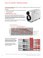
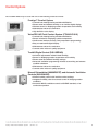
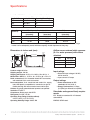
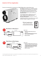
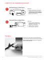
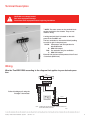
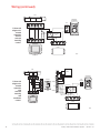
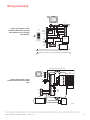
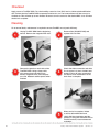
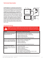
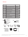
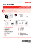
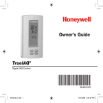
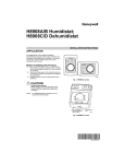
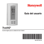
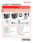
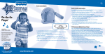
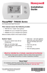
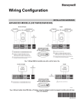
TrueDRY™ DR90
PROFESSIONAL INSTALLATION GUIDE
Included in this Box
C
B
D
E
A
F
OPTIONAL CONTROLS SOLD SEPARATELY
G
TrueDRY™ DR90
PROFESSIONAL INSTALLATION GUIDE
INCLUDED IN THIS BOX
B
C
D
E
A
F
OPTIONAL CONTROLS SOLD SEPARATELY
G
TrueDRY™ DR90
PROFESSIONAL INSTALLATION GUIDE
INCLUDED IN THIS BOX
B
C
D
E
A
F
OPTIONAL CONTROLS SOLD SEPARATELY
G
G1
Tools required to install TrueDRY DR90
3/8-in. hex drive
Drill or duct cutting tool
Wire stripper/cutter
Standard screwdriver
Duct tape
10-in. round duct and starter collar
18-22 gauge, 5 band thermostat wire
1/2-in. diameter drain line (8 ft.)
1/2-in. drain clamps (2)
Options
1/2-in. drain p-trap (may be required by local code)
Drain pan
G2
G3
A
B
C
D
E
F
G4
TrueDRY™ DR90 (1)
10-in. duct collar (1)
6-in. duct collar (1)
MERV II Filter (1)
Filter Door (1)
Installation Guide
G1
Prestige Comfort System (wireless)
G2
TruelAQ
G3
H8908 Manual Dehumidistat
G4
VisionPRO IAQ control (included with
DR90VPIAQ)
69-2407-01
G1
Tools required to install TrueDRY DR90
3/8-in. hex drive
Drill or duct cutting tool
Wire stripper/cutter
Standard screwdriver
Duct tape
10-in. round duct and starter collar
18-22 gauge, 5 band thermostat wire
1/2-in. diameter drain line (8 ft.)
1/2-in. drain clamps (2)
Options
1/2-in. drain p-trap (may be required by local code)
Drain pan
G2
G3
A
B
G4
TrueDRY™ DR90 (1)
10-in. duct collar (1)
C
6-in. duct collar (1)
D
MERV II Filter (1)
E
Filter Door (1)
F
Installation Guide
G1
Prestige Comfort System (wireless)
G2
TruelAQ
G3
H8908 Manual Dehumidistat
G4
VisionPRO IAQ control (included with
DR90VPIAQ)
69-2407-01
G1
G2
G3
G4
Tools required to install TrueDRY DR90
A
TrueDRY™ DR90 (1)
B
10-in. duct collar (1)
C
6-in. duct collar (1)
D
MERV II Filter (1)
E
Filter Door (1)
F
Installation Guide
G1
Prestige Comfort System (wireless)
G2
TruelAQ
G3
H8908 Manual Dehumidistat
G4
VisionPRO IAQ control (included with
DR90VPIAQ)
3/8-in. hex drive
Drill or duct cutting tool
Wire stripper/cutter
Standard screwdriver
Duct tape
10-in. round duct and starter collar
18-22 gauge, 5 band thermostat wire
1/2-in. diameter drain line (8 ft.)
1/2-in. drain clamps (2)
Options
1/2-in. drain p-trap (may be required by local code)
Drain pan
69-2407-01
Installation Checklist
Included in This Box
A TrueDRY™ DR90 (1)
B 10-in. duct collar (2)
C 6-in. duct collar (1)
D MERV II Filter (1)
E Filter Door (1)
F Installation Guide
Control Options (Sold separately)
G1Prestige Comfort System
G2True IAQ
G3H8908 Manual Dehumidistat
G4VisionPro IAQ Control
(included with DR90VPIAQ)
Tools Required (Not Supplied)
• 3/8-in. hex drive
• Drill or duct cutting tool
• Wire stripper/cutter
• Standard screwdriver
• Duct tape
• 10-in. round duct and starter
collar
• 18-22 gauge, 5 band
thermostat wire
• 1/2-in. diameter drain line (8 ft.)
• 1/2-in. drain clamps (2)
Options
• 1/2-in. drain p-trap (may be
required by local code)
• Drain pan
Warning: Installation must be
performed by a qualified service
technician and must comply
with local codes.
Remove power to the device
before installing or servicing the
device.
Failure to connect the device
according to these instructions
may result in damage to the
device or the controls.
INSTALLATION INSTRUCTIONS
BEGIN ON PAGE 1
TrueDRY
TM
ABOUT YOUR NEW DEHUMIDIFIER
Benefits . . . . . . . . . . . . . . . . . . . . . . . . . . . . . . . . . . .
Maintaining Ideal Humidity . . . . . . . . . . . . . . . . . . . .
Control Options . . . . . . . . . . . . . . . . . . . . . . . . . . . . .
Specifications. . . . . . . . . . . . . . . . . . . . . . . . . . . . . . .
2
2
3
4
INSTALLATION
Install to Fit Your Application. . . . . . . . . . . . . . . . . . . 5
Plumbing. . . . . . . . . . . . . . . . . . . . . . . . . . . . . . . . . . . 6
Terminal Description. . . . . . . . . . . . . . . . . . . . . . . . . . 7
Wiring . . . . . . . . . . . . . . . . . . . . . . . . . . . . . . . . . . . 7
Checkout. . . . . . . . . . . . . . . . . . . . . . . . . . . . . . . . . . 10
MAINTENANCE
Cleaning. . . . . . . . . . . . . . . . . . . . . . . . . . . . . . . . . .
Technical Description. . . . . . . . . . . . . . . . . . . . . . . .
Troubleshooting. . . . . . . . . . . . . . . . . . . . . . . . . . . .
Refrigerant Charging . . . . . . . . . . . . . . . . . . . . . . . .
Compressor/Capacitor Replacement. . . . . . . . . . .
Parts List. . . . . . . . . . . . . . . . . . . . . . . . . . . . . . . . . .
5-Year Limited Warranty. . . . . . . . . . . . . . . . . . . . . .
10
11
11
12
12
13
14
• The TrueDRY™ DR90 is designed to be installed indoors in a space that is protected from rain and
flooding.
• Install the unit with space to access the front panel for maintenance and service.
• Avoid directing the discharge air at people, or over the water in pool areas.
• If used near a pool or spa, be certain there is no chance the unit could fall into the water or be splashed,
and that it is plugged into a ground fault interrupt (GFI) outlet.
• To ensure quiet operation, do not place the device directly on the structural supports of the home.
• A drain pan must be placed under the unit if installed above a living area or above an area where water
leakage could cause damage.
?
NEED HELP? For assistance with this product please visit http://yourhome.honeywell.com
or call Honeywell Customer Care toll-free at 1-800-468-1502.
Read and save these instructions.
® U.S. Registered Trademark. Patents pending. Copyright © 2010 Honeywell International Inc. All rights reserved.
TrueDRY™ DR90 Dehumidification System
69-2407—01
1
About the TrueDRY™ DR90 Dehumidifier
The Honeywell TrueDRY DR90 ensures the home is maintained at proper humidity levels through its high
performance and efficiency.
Benefits
• Removes up to 90 pints of water per day from the indoor air.
• Built-in fresh air supply
• Energy Star Rated
Maintaining Ideal Humidity
Dew points and relative humidity (RH) affect the way your
body senses heat. Higher humidity levels cause the air to feel
much hotter than the actual temperature. When maintained
properly, your cooling equipment may not run as much because
dehumidified air feels cooler.
Ideal humidity is defined by industry experts* as being between
40-60% on an average annual basis.
WHAT THE AIR FEELS LIKE
HOW HOT THE HEAT-HUMIDITY COMBINATION MAKES IT FEEL.
EXAMPLE: AIR AT 90ºF WITH 50% RH FEELS LIKE 96ºF TO THE HUMAN BODY!
AIR TEMPERATURE
(DEGREES FAHRENHEIT)
RELATIVE HUMIDITY (PERCENTAGE)
0
5
10
15
20
25
100
91
93
95
97
99 101 104 107 110 115 120 126 132 138 144
30
35
40
45
50
55
60
65
70
75
80
95
87
88
90
91
93
94
96
98 101 104 107 110 114 118 124 130 136
85
90
95 100
90
83
84
85
86
87
88
90
91
93
95
96
98
100 102 106 109 113 117 122
85
78
79
80
81
82
83
84
85
86
87
88
89
90
91
93
95
97
99 102 105 108
80
73
74
75
76
77
77
78
79
79
80
81
81
82
83
85
86
86
87
88
89
EXTREME DANGER
91
DANGER
75
69
69
70
71
72
72
73
73
74
74
75
75
76
76
77
77
78
78
79
79
80
EXTREME CAUTION
70
64
64
65
65
66
66
67
67
68
68
69
69
70
70
70
71
71
71
71
71
72
CAUTION
SOURCE: TEMPERATURE - HUMIDIY INDEX WAS DERIVED BY R.G. STEADMAN, JOURNAL OF APPLIED METEOROLOGY, JULY 1979.
When indoor humidity exceeds 60%,
the home is more susceptible to
mold and mildew growth. TrueDRY
DR90 safeguards against excessive
humidity in the home year-round.
*American Society of Heating,
Refrigerating and Air Conditioning
Engineers (ASHRAE).
M27328
OPTIMUM
ZONE
ASHRAE RECOMMENDED WINTER DESIGN LEVEL
BACTERIA
VIRUSES
FUNGI
MITES
RESPIRATORY
INFECTIONS
ALLERGIC RHINITIS
AND ASTHMA
CHEMICAL
INTERACTIONS
OZONE
PRODUCTION
0
10
20
30
40
50
60
70
80
90
100
MCR24780
2
TrueDry DR90 Dehumidification System
69-2407—01
Control Options
The TrueDRY DR90 may be used with one of the following external controls:
Prestige™ Comfort System
• Controls both heating/cooling and dehumidification.
• Shows actual and desired humidity on an intuitive digital display.
• Wireless sensor for displaying outdoor temperature and humidity.
• Maintenance and service reminders.
• High definition color display.
VisionPRO IAQ Total Comfort System (YTH9421C1010)
• Controls both heating/cooling and dehumidification.
• Sensor included for displaying outdoor temperature.
• Intuitive user interface for easy 7-day temperature programming.
• Easy-to-read backlit digital display.
• Maintenance and service reminders.
• Controls other indoor air quality equipment.
TrueIAQ Digital Control (DG115EZIAQ)
• Automatic adjustments maintain ideal humidity.
• Sensor for displaying outdoor temperature and humidity.
• Shows actual and desired humidity settings.
• Advanced ventilation programming includes economizing and extreme
condition shutdown.
• Maintenance and service reminders.
• Controls other indoor air quality equipment.
Manual Dehumidistat (H8908DSPST) and Automatic Ventilation
Controls (W8150A1000)
• Manual humidity control with intuitive comfort settings.
• Integrated humidity chart for accurate control in changing outdoor
conditions.
• Automatic W8150 ventilation control to ASHRAE standard, or for
continuous operation.
TrueDry DR90 Dehumidification System
69-2407—01
3
Specifications
Install TrueDRY DR90 according to National Electric Codes.
Dry-Bulb Temp
Intake Humidity Capacity (Pints/Day)
80°F
60% RH
90
70°F
60% RH
77
60°F
60% RH
47
Home Size
(square ft)
Dehumidifier Capacity Required to Maintain Desired Indoor RH*
60% RH Indoor
(pints/day)
50% RH Indoor
(pints/day)
40% RH Indoor
(pints/day)
2080
49–54
55–58
71–78
2600
61–68
65–72
90–97
3120
75–82
79–86
95–110
* Based on extreme climates where outdoor humidity is 70-90% RH. For less extreme climates, larger
homes can be adequately served with less capacity. Actual requirements may vary.
Dimensions in inches and (mm):
14 3/8 (365)
3 3/16
(81)
33 7/16 (849)
3 3/16
(81)
21 9/32
(541)
Airflow versus external static pressure
(0–1 in. water pressure) with collars
attached
0 in.
235 CFM
0.2 in.
210 CFM
0.4 in.
195 CFM
0.6 in.
175 CFM
M28840
Product weight: 92.2 lbs.
Shipping weight: 102 lbs.
Shipping dimensions: 21.5 in. H x 18.5 in. W x 40.2 in. L
Media Filter: MERV 11, 13.75 in. H x 13.75 in. W x .75 in. D
Drain connection: 3/4-in. threaded female NPT connection,
with attached 3/4-in. male connection.
Duct connections: 10-in. round inlet and outlet. 6-in. supply
inlet. ABS plastic, compatible for connection to rigid or
flexible ducting with sheet metal screws and/or tape.
Cabinet: 20 gauge galvanized steel powder-coat painted.
Insulation: R value 1
Compressor: Rotary-style, 6.8 KBTU
Refrigerant: R-410A, 1.0 lbs.
Operating Temp Range (outside cabinet):
34ºF to 135ºF (1.1ºC to 57.2ºC)
Operating Humidity Range: 0-99% RH
4
Input ratings
• Electrical input voltage: 120 VAC,
60 Hz nominal
• Input current: 6.7 amps
Output ratings
• Power transformer to R/C
terminals: 24 VAC, 0.85 A
• Energy Performance: 2.5 liters
(5.3 pints) per kilowatt hour (KWH)
Standards and approval body requirements
ETL Tested per standard UL 474 ducted
dehumidifier.
ENERGY STAR rated.
TrueDry DR90 Dehumidification System
69-2407—01
Install to Fit Your Application
Flex duct is recommended in connecting to the TrueDRY DR90 collars to reduce vibration noise.
Duct Sizing: Use minimum 10-in. diameter round for
duct lengths up to 25 ft. Minimum 12-in. required for
lengths longer than 25 ft. Duct branches from the
main inlet/exhaust should be minimum 10-in. round
for 2-3 branches, and 12-in. round or larger for 4
branches or more.
For the optional fresh air ventilator port, use 6-in.
round, insulated duct for lengths up to 50 ft.
Use 8-in. round duct for more than 50 ft. of if more
than 100 CFM is required.
Isolated Areas: Effective dehumidification may require
ducting to isolated or stagnant air flow areas.
Electrical requirements:
115 VAC outlet. Ground fault
interrupter (GFI) recommended.
M24745
A
Main Return to Main Return
Ideal when…
AIR HANDLER
RETURN
SUPPLY
• Running TrueDRY DR90 with A/C
operation.
• Minimizing discharge air temperature
(DAT) increase is preferred.
M27325
TrueDRY
B
• Space dictates.
Main Return to Main Supply
Ideal when…
AIR HANDLER
RETURN
SUPPLY
TrueDRY
• Running TrueDRY DR90 opposite A/C
operation. Running with A/C operation
requires damper on the exhaust port
to minimize backdraft when TrueDRY
DR90 is not on but A/C is.
BACKDRAFT
DAMPER
• Space dictates.
M27324
TrueDry DR90 Dehumidification System
69-2407—01
5
Install to Fit Your Application (continued)
C
Dedicated Return to Main Supply
Ideal when…
AIR HANDLER
RETURN
SUPPLY
• Drying a specific area of the house.
• Running with A/C operation requires
backdraft damper on the exhaust port
to minimize backdraft when TrueDRY
DR90 is not on but A/C is.
SEPARATE
RETURN
TrueDRY
D
BACKDRAFT
DAMPER
M27326
Dedicated Return to Main Return
AIR HANDLER
RETURN
SUPPLY
Ideal when…
• Drying a specific conditioned or
unconditioned area, such as attic,
basement, or crawl space.
• Running with A/C operation.
• Minimizing DAT is preferred.
SEPARATE
RETURN
TrueDRY
M27601
Plumbing
Connect 1/2-in. drain tube to male connection drain
outlet. Secure drain tube to connector with hose clamp.
Run drain hose continuously downhill to an approved
drain or condensate pump.
6
TrueDry DR90 Dehumidification System
69-2407—01
Terminal Description
CAUTION: Low voltage hazard.
Can cause equipment damage.
Disconnect HVAC equipment before beginning installation.
* NOTE: The outer screws on the terminal block
secure the block to the chassis. They are not
used for wiring.
A wiring terminal block is located on the side
panel of the TrueDRY unit.
The four terminals for the terminal block (reading
from left to right in the photo) are:
DHUM: Compressor and fan operation for
dehumidification
R: DR90 24V output
FAN: Fan activation only for ventilation
C: DR90 24V output
External 24V devices can be powered from R and
C terminals (20VA max.)
Wiring
Wire the TrueDRY DR90 according to the diagram that applies to your desired operation.
HVAC
R
C
W
Y
G
W
Follow this diagram if using the
Prestige™ thermostat.
W2
C
Y
Rc
Y2
R
G
H
TrueDRY
H
DH
K
THERMOSTAT
+
+
DH
DHUM R FAN C
NOTE: THERMOSTAT MUST BE CONFIGURED TO DRIVE FURNACE FAN
DURING DEHUMIDIFICATION CALL.
M29839
TrueDry DR90 Dehumidification System
69-2407—01
7
Wiring (continued)
HVAC
MECHANICAL
DEHUMIDISTAT
R
W
Y
G
DRY
CONTACTS
DPDT RELAY,
2.6A
Rc
W
Y
G
+
R
+
Follow this
diagram for
ducted
operation
with an
external
humidity
control.
C
DHUM
R
FAN
TrueDRY
C
M29840
THERMOSTAT
HVAC
AT120
EARD-6
R
C
W
Y
G
G
R
W8150A
C
DRY
CONTACTS
DAMPER
C
C
AUX
W
G
Rc W
Y
G
+
R
DPDT
RELAY,
2.6A
REMOTE
+
Follow this
diagram for
ducted
operation
with
external
humidity
and
ventilation
control.
MECHANICAL
DEHUMIDISTAT
R
DHUM
R
FAN
TrueDRY
C
THERMOSTAT
M29841
8
TrueDry DR90 Dehumidification System
69-2407—01
Wiring (continued)
THERMOSTAT
1
R Rc C W Y
Follow this diagram if using
TrueDRY DR90 with a powered
dehumidistat such as TrueIAQ
(DG115EZIQ).
HVAC
G
R
TrueIAQ
68 40
76 55
SENSOR
SENSOR
In
C
OUTDOOR
SENSOR
(PROVIDED)
W
Y
SWITCH
%
Out
2
R
C
%
G
W
12:15
PM
G
VENT
EARD-6
VENT
DEHUM
DEHUM
C
R
FAN
+
DHUM
HUM
TrueDRY
+
HUM
1
IF A THERMOSTAT OTHER THAN A TH5110, TH5220, TH5320, TH6110, TH6220, TH6320, TH8110,
TH8320, OR TH8321 IS USED, A RELAY MAY BE REQUIRED TO ISOLATE THE G WIRE.
2
PROGRAM ISU SETTING 60 TO Ø TO FORCE SYSTEM FAN ON WITH DEHUMIDIFICATION CALL.
M29842
EQUIPMENT INTERFACE MODULE (EIM)
D-1
R-2
C-3
VISIONPRO IAQ
Follow this diagram if using
TrueDRY DR90 with a VisionPRO
IAQ).
DHUM
+
FAN
C
CONV. HP
2
W1
O/B
3
W2
AUX
C
W3
AUX2
R
Y
Y
RC
Y2
Y2
RH
G
G
HEAT 1 RELAY
HEAT 2 RELAY
HEAT 3 RELAY
COOL 1 RELAY
COOL 2 RELAY
G
FAN RELAY
H1
U
M2
D1
H
M2
R
+
C
FAN
FURNACE BOARD
1
OR
V1
N
T2
TrueDRY
EARD-6
M29843
TrueDry DR90 Dehumidification System
69-2407—01
9
Checkout
Apply power to TrueDRY DR90. Turn the humidity control to a low RH% level to initiate a dehumidification
call. Confirm that the TrueDRY DR90 compressor and fan turn on. The furnace blower will also turn on to
circulate air. This will take up to two minutes. Be sure to turn the control to the desired RH% or to Off when
checkout is complete.
Cleaning
On an annual basis, maintenance is required to ensure TrueDRY runs at peak efficiency.
1
3
Unplug TrueDRY DR90 before beginning
service. Remove the magnetic filter door.
Remove the panels on each side of the
TrueDRY DR90. Using a damp cloth,
wipe excess dust and debris from
blower, refrigerant coils, and compressor coils. Reattach cabinet panels when
finished.
2
4
5
10
Remove filter (50049537-005) and
replace with new filter.
Check the drain connection and drain
line to ensure it is clear of debris and
sludge. Ensure all hose connections
are secure once maintenance of the
drain lines is complete.
When service is complete, initiate
a call for dehumidification and
check that the compressor and fan
activate. If using the VisionPRO IAQ or
TrueIAQ controls, reset maintenance
reminders.
TrueDry DR90 Dehumidification System
69-2407—01
Technical Description
TrueDRY DR90 uses a refrigeration system similar to
an air conditioner to remove heat and moisture from
incoming air and add heat to the air that is discharged.
Hot, high-pressure refrigerant gas is routed from the
compressor to the condenser coil. The refrigerant is
cooled and condensed by giving up its heat to the
air that is about to be discharged from the unit. The
refrigerant liquid then passes through a filter drier and
capillary tubing which causes the refrigerant pressure
and temperature to drop. It next enters the evaporator
coil where it absorbs heat from the incoming air and
evaporates. The evaporator operates in a flooded
condition, which means that all the evaporator tubes
contain liquid refrigerant during normal operation. A
flooded evaporator should maintain nearly constant
pressure and temperature across the entire coil, from
inlet to outlet.
STRAINER/FILTER
DRIER
COMPRESSOR
CONDENSER
CAPILLARY
TUBES
EVAPORATOR
ACCUMULATOR
M27404
Troubleshooting
CAUTION: Servicing the TrueDRY DR90 with its high pressure refrigerant system and high
voltage circuitry presents a health hazard which could result in death, serious bodily injury,
and/or property damage. Service should only be performed by a qualified service technician.
Problem
Recommended Troubleshooting Steps
No dehumidification. Neither
fan nor compressor run and the
ventilation timer is OFF.
1.
2.
3.
4.
5.
6.
Unit unplugged or no power to outlet.
Humidity control set too high or defective.
Loose connection in internal or control wiring.
Defective Compressor relay.
Defective control transformer.
Optional Condensate Pump Safety Switch open.
No dehumidification. Compressor
does not run but fan runs when
there is a call for dehumidification
and the ventilation control is OFF.
1.
2.
3.
4.
5.
6.
Defective compressor run capacitor.
Bad connection in compressor circuit.
Defective compressor overload.
Defective compressor.
Defrost thermostat open.
Optional Condensate Pump Safety Switch open.
Fan runs when there is a call
for dehumidification and the
ventilation control is OFF, but the
compressor cycles on and off too
frequently.
1. Low ambient temperature and/or humidity causing unit to cycle
through defrost mode.
2. Defective compressor overload.
3. Defective compressor.
4. Defrost thermostat defective.
5. Dirty air filter(s) or airflow restricted.
6. Low refrigerant charge, causing defrost control to cycle.
7. Bad connection in compressor circuit..
TrueDry DR90 Dehumidification System
69-2407—01
11
Troubleshooting (continued)
Problem
Recommended Troubleshooting Steps
Fan does not run with
ventilation activated.
Compressor runs briefly
but cycles on & off with
humidity control turned to
ON.
1.
2.
3.
4.
5.
Evaporator coil frosted
continuously, low dehumidifying capacity.
1. Defrost thermostat loose or defective.
2. Low refrigerant charge.
3. Dirty air filter(s) or airflow restricted.
Unit not providing
ventilation.
1. Check control wire connections (check connections at fresh air damper
also).
2. Defective fresh air damper.
3. Dirty air intake. Clean outside intake hood.
Unit removes some
water, but not as much as
expected.
1. Air temperature and/or humidity have dropped.
2. Humidity meter and or thermometer used are out of calibration.
3. Unit has entered defrost cycle.
4. Air filter dirty.
5. Defective defrost thermostat.
6. Low refrigerant charge.
7. Air leak such as loose cover or ducting leaks.
8. Defective compressor.
9. Restrictive ducting.
10.Optional Condensate Pump Safety Switch open.
Unit Test to determine
problem:
1. Detach field control wiring connections from main unit.
2. Connect the R and FAN contacts from the main unit together; only the
impeller fan should run. Disconnect the wires.
3. Connect the R and DHUM contacts from the main unit together; the
compressor and impeller fan should run.
4. If these tests work, the main unit is working properly. You should check
the control panel and field control wiring for problems next.
5. Remove the control panel from the mounting box and detach it from the
field installed control wiring. Connect the blue, yellow, and green wires
from the control panel directly to the corresponding colored pigtails on
the main unit. Leave the violet, white, and red wires disconnected!
6. Turn on the humidity control. The compressor and impeller fan should
run.
7. If these tests work, the problem is most likely in the field control wiring.
Loose connection in fan circuit.
Obstruction prevents fan rotation.
Defective fan.
Defective fan relay.
Defective fan capacitor.
Refrigerant Charging
If the refrigerant charge is lost due to service or a leak, a new charge must be accurately weighed in. If any
of the old charge is left in the system, it must be recovered before weighing in the new charge. Refer to the
unit nameplate for the correct charge weight and refrigerant type.
Compressor/Capacitor Replacement
This compressor is equipped with a two terminal external overload and a run capacitor, but no start
capacitor or relay.
12
TrueDry DR90 Dehumidification System
69-2407—01
Parts List
Figure
Reference
1
Description
Part Number
1
TrueDRY with no controls
DR90A1000
2
TrueDRY with VisionPRO IAQ Control
DR90VPIAQ
3
Prestige Comfort System
YTHX9321R5003
4
VisionPRO IAQ Total Comfort Control
YTH9421C1010
5
TrueIAQ Digital IAQ Control
DG115EZIAQ
6
H8908D Manual Dehumidistat
H8908DSPST
7
Automatic ventilation control
W8150A1001
8
Motorized ventilation damper
EARD 6
Compressor run capacitor
50049536-001
Blower assembly
50027976-001
9
Filter
50049536-003
10
6-in. Duct collar
50049536-004
11
10-in. Duct collar
50049536-005
12
Magnetic door
50049536-006
Compressor relay, SPST, 24 Vac, 30A
50035445-014
Fan relay, SPDT, 24 Vac, 15A
50035445-011
Transformer 120/24 Vac, 40 VA
50035445-013
2
3
4
5
9
6
10
7
11
8
12
M28837
TrueDry DR90 Dehumidification System
69-2407—01
13
5-Year Limited Warranty
Honeywell warrants this product to be free from defects in the workmanship or materials, under normal use
and service, for a period of five (5) years from the date of purchase by the consumer. If at any time during
the warranty period the product is determined to be defective or malfunctions, Honeywell shall repair or
replace it (at Honeywell’s option).
If the product is defective,
(i) return it, with a bill of sale or other dated proof of purchase, to the place from which you purchased it; or
(ii) call Honeywell Customer Care at 1-800-468-1502. Customer Care will make the determination whether
the product should be returned to the following address: Honeywell Return Goods, Dock 4 MN10-3860,
1885 Douglas Dr. N., Golden Valley, MN 55422, or whether a replacement product can be sent to you.
This warranty does not cover removal or reinstallation costs. This warranty shall not apply if it is shown by
Honeywell that the defect or malfunction was caused by damage which occurred while the product was in
the possession of a consumer.
Honeywell’s sole responsibility shall be to repair or replace the product within the terms stated above.
HONEYWELL SHALL NOT BE LIABLE FOR ANY LOSS OR DAMAGE OF ANY KIND, INCLUDING ANY
INCIDENTAL OR CONSEQUENTIAL DAMAGES RESULTING, DIRECTLY OR INDIRECTLY, FROM ANY
BREACH OF ANY WARRANTY, EXPRESS OR IMPLIED, OR ANY OTHER FAILURE OF THIS PRODUCT. Some
states do not allow the exclusion or limitation of incidental or consequential damages, so this limitation may
not apply to you.
THIS WARRANTY IS THE ONLY EXPRESS WARRANTY HONEYWELL MAKES ON THIS PRODUCT. THE
DURATION OF ANY IMPLIED WARRANTIES, INCLUDING THE WARRANTIES OF MERCHANTABILITY AND
FITNESS FOR A PARTICULAR PURPOSE, IS HEREBY LIMITED TO THE FIVE-YEAR DURATION OF THIS
WARRANTY. Some states do not allow limitations on how long an implied warranty lasts, so the above limitation may not apply to you.
This warranty gives you specific legal rights, and you may have other rights which vary from state to state.
If you have any questions concerning this warranty, please write Honeywell Customer Relations, 1985
Douglas Dr, Golden Valley, MN 55422 or call 1-800-468-1502. In Canada, write Retail Products ON15-02H,
Honeywell Limited/Honeywell Limitée, 35 Dynamic Drive, Toronto, Ontario M1V4Z9.
Automation and Control Solutions
Honeywell International Inc.
1985 Douglas Drive North
Golden Valley, MN 55422
Honeywell Limited-Honeywell Limitée
35 Dynamic Drive
Toronto, Ontario M1V 4Z9
http://yourhome.honeywell.com
® U.S. Registered Trademark.
© 2010 Honeywell International Inc.
69-2407—01 M.S. 01-10
Printed in U.S.A