1
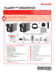
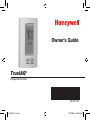
Owner’s Guide
TrueIAQ®
Digital IAQ Control
69-2072-05
69-2072_C.indd 1
7/31/2008 2:04:24 PM
Table of contents
User Information
®
About TrueIAQ ............................... 1
Operation..................................... 2
Display screen reference............ 3
Adjusting IAQ settings
Changing humidifier settings...... 4
Changing dehumidifier settings.... 6
Changing ventilation settings....... 6
Changing time of day.................. 7
Service timers.............................. 7
Installer Information
Installation................................... 8
Wiring......................................... 10
Mounting the outdoor sensor......16
Advanced programming........... 17
Appendices
Standards.................................. 21
Warranty information................. 22
Need Help?
For assistance with this product please visit http://yourhome.honeywell.com
or call Honeywell Customer Care toll-free at 1-800-468-1502
Read and save these instructions.
® U.S. Registered Trademark. Patents pending. Part number DG115EZIAQ.
Copyright © 2008 Honeywell International Inc. All rights reserved.
69-2072_C.indd 2
7/31/2008 2:04:24 PM
About TrueIAQ®
The TrueIAQ® monitors and automatically adjusts operation of your whole-house humidifier, dehumidifier, ventilator, or bath fan.
Maintaining proper indoor humidity minimizes the potential for unhealthy airborne pollutants to grow. Having too little humidity can leave you vulnerable to infections and
uncomfortable dry skin. Too much humidity creates ideal breeding grounds for mold,
mildew and dust mites. Humidified air also feels warmer in the winter, and dry air feels
cooler in the summer.
TrueIAQ can adjust humidity with or without dependency on HVAC equipment operation. If you have both a humidifier and dehumidifier installed, the TrueIAQ can automatically change over to the appropriate equipment based on your comfort settings and the
changing outdoor conditions.
TrueIAQ can also deliver fresh air with or without dependency on HVAC equipment
operation. Today’s building codes require homes to be built more tightly for energy efficiency, but that tightness can also trap indoor air pollutants, such as cooking odors,
cleaning agents, radon, and carbon dioxide/monoxide. TrueIAQ provides cost-effective
ventilation in accordance to industry standards. In addition, the TrueIAQ can be programmed to deliver ventilation during set times of the day or night.
69-2072_C.indd 1
1
69-2072—05
7/31/2008 2:04:24 PM
Operation
TrueIAQ® can be used to control the humidity levels in your home, and control fresh air
intake in accordance to industry recommendations (ASHRAE 62.2).
Comfort Settings: Feedback
on your indoor IAQ conditions.
1
Outdoor Conditions : Actual
outdoor temperature and
humidity.
Indoor Conditions: Actual
indoor temperature and
humidity.
68 40
76 55
In
Programmable Clock:
Displays time and allows
IAQ equipment programming
based on time.
%
Out
%
12 : 15
Maintenance Reminders:
Notifies you when your equipment needs service.
PM
Equipment Operation:
Displays what equipment is
operating at a given time.
Done: Saves changes.
More: Advances between
installed IAQ equipment control
options.
Toggle Arrows: Changes the
comfort levels of your IAQ
equipment operation.
M24931
1
Actual outdoor temperature and humidity will only be displayed if the outdoor sensor is installed.
69-2072—05
69-2072_C.indd 2
2
7/31/2008 2:04:24 PM
Display screen reference
Wet: Indoor
humidity levels are
above 60% RH.
Dry: Indoor humidity levels
are below 20% relative
humidity (RH.)
68 40
76 55
In
%
Out
De Humidify: If “Humidify” is displayed, the control is calling for
more humidity. If “DeHumidify” is
displayed, the control is calling for
humidity removal.
%
12 : 15
PM
Window Frost: The control is
protecting your home against too
much humidity based on outdoor
conditions. Humidity levels in your
home may not reach your desired
RH% setting as a result.
Indoor temperature
and humidity.
Outdoor temperature
and humidity.
Ventilate: Fresh air ventilation
is on.
M24932
Service Reminders: All are timer-based
and will be displayed to indicate what
service is needed.
69-2072_C.indd 3
3
69-2072—05
7/31/2008 2:04:24 PM
Changing humidifier settings
Note: These items will appear only if a humidifier is installed on your system.
1.Set humidifier by pressing UP/DOWN arrows.
35
Tables below are recommended initial humidity settings based on
outdoor temperature. If window frost setting (see next page) is not
being used, the humidity setting should be adjusted manually when
outdoor conditions change.
Outdoor Temp.
Setting
-20°F (-29°C)
15%
0°F (-18°C)
25%
20°F (-7°C)
35%
%
Humidify
Set
M24831
Red font is
blinking on
screen.
If both humidifier (hum) and dehumidifier (dehum) are installed:
Dehum setpoint can only be equal to or higher than Hum setpoint. If equal, equipment
changeover will be at least 5% higher (dehum) or lower (hum).
If not equal, changeover occurs at setpoint plus 2% RH (control’s deadband).
69-2072—05
69-2072_C.indd 4
4
7/31/2008 2:04:24 PM
Changing humidifier settings
2.Press “More” to enter Window Frost Protection. Use the UP/DOWN
arrows to set frost protection level.
MORE HUMIDITY
LESS HUMIDITY
TIGHT HOME/TRIPLE-PANE WINDOWS
LOOSE HOME/SINGLE-PANE WINDOWS
1
2
3
4
5
6
7
8
9
Window Frost
7
Humidify
M24830
On the first cold day after TrueIAQ is installed, look for condensation
on windows. If present, lower Frost Protection by one. Once set for your
home, Frost Protection does not need to be changed again.
3.Press “More” again to enter operation style. Press the UP/DOWN
arrows to set.
M24832
®
• “Auto” runs humidifier automatically according to settings.
• “Off” turns the humidifier off.
Auto
Humidify
Off
M24833
4.Press “Done” to save settings, or “More” to enter dehumidifier
settings.
69-2072_C.indd 5
5
69-2072—05
7/31/2008 2:04:24 PM
Changing dehumidifier and ventilation settings
Note: These items will appear only if a dehumidifier is installed. If both a humidifier
and dehumidifier are installed, these settings will appear after pushing “More” from the
humidifier operation style screen.
%
1.Set dehumidifier by pressing the UP/DOWN arrows. RH% will change
in increments of five.
DeHumidify
2.Press “More” to enter operation style. Press the UP/DOWN arrows to
Set
set.
60
• “Auto” runs dehumidifier automatically according to your RH%
settings.
• “Off” turns the dehumidifier off.
M24834
Auto
DeHumidify
Off
3.Press “Done” to save settings, or “More” to enter ventilation settings.
Note: These items will appear only if a ventilator is installed.
1.Use the UP/DOWN arrows to run ventilation temporarily. Range is
from 20 to 480 minutes, in 20-minute increments.
2.Press “More” again to enter operation style.
• “Auto” runs ventilation according to installer settings.
• “ON” runs ventilation continuously.
• “OFF” turns ventilation off. In this mode, ventilation will only
run if turned on by a remote switch.
3.Press “Done” to save settings, or “More” to enter time settings.
69-2072—05
69-2072_C.indd 6
M24835
Time On
Ventilate
00 20
M24836
Auto
On Off
Ventilate
M24837
6
7/31/2008 2:04:25 PM
68 40
Changing time of day and service timers 76 55
In
%
Out
%
12 : 00
Set
1.Press “More.” Adjust hour using the the UP/DOWN
arrows.
2.Press “More.” Adjust minutes using the UP/DOWN
arrows.
3.Press “Done” to save settings.
68 40
76 55
In
%
Out
%
M24934
12 : 00
Set
68 40
76 55
In
%
Out
Service Timers
%
12 : 15
PM
Service timers appear when the humidifier, dehumidifier,
ventilator, air filter, and/or UV bulbs need service. Your HVAC
technician will set these timers during installation.
M24935
Resetting Service Timers
Press and hold the DOWN arrow for 5 seconds to reset your
service timers.
M24933
69-2072_C.indd 7
7
69-2072—05
7/31/2008 2:04:25 PM
Installation
CAUTION: ELECTRICAL HAZARD. Can cause electrical shock or
equipment damage. Disconnect power before beginning installation.
1.Turn system power off.
2.Choose a location. TrueIAQ® can be mounted to a wall or directly to the return duct.
ELECTRON
IC
AIR
CLEANER
M24787
69-2072—05
69-2072_C.indd 8
8
7/31/2008 2:04:25 PM
Installation
3.Loosen the cover screw.
4.Separate the front housing from the base.
M24814
5.For wall mounting, run wires through
the back hole to the terminals. Wire
size for all connectors:
2 x 18 AWG to 1 X 22 AWG.
Install the mounting plate using two
screws.
M24818
A
6.For duct mounting, (A) snap out side wall clip and attach
as shown. Run wires through the side wall hole, under
the clip, to the terminals. (B) Snap in sensor cap.
7.Reinstall the front housing on the power base, and
secure with screw.
Note: If duct mounted, ensure sensor cap tip aligns with
air flow in duct.
8.Apply power to the system.
B
69-2072_C.indd 9
9
M24854
69-2072—05
7/31/2008 2:04:25 PM
Wiring
Pin
R
Pin description
Pin capacity
24V supply. Must be common to G output. 24Vac±20% 1.5
amp max
C
24V supply common.
24Vac±20%
Sensor Communication and supply bus to remote 24Vdc 64mA max
out
Sensor sensors (sensor pins not polarized).
Switch Override switch input. Active when R is
24Vac±20%,
applied
10mA max in
W
W input to sense when the thermostat is
24Vac±20%,
calling for heat. Active when R is applied. 10mA max in
G
G input to sense fan calls. Active when R is 24Vac±20%,
applied. Fan output to activate system fan. 10mA max in
R8222 Isolation Relay may be required if G 24Vac from R,
is not isolated through the thermostat.
1Amp max out
Vent 1
Dry contact output. Opens the vent
24Vac from R,
damper of an HRV or the bathroom fan
1Amp max out
Vent 2
and Damper.
Dehum 1 Dry contact output. Starts the
24Vac from R,
1Amp max out
Dehum 2 Dehumidifier or an alternate fan speed.
Hum 1
Dry contact output. Starts the Humidifier.
24Vac from R,
1Amp max out
Hum 2
M24819
69-2072—05
69-2072_C.indd 10
10
7/31/2008 2:04:26 PM
Wiring
Wiring TrueIAQ® with a non-powered humidifier.
R
C
TrueIAQ
68 40
76 55
In
%
SENSOR
+
24V
– TRANSFORMER
THERMOSTAT
R
SENSOR
C
SWITCH
W
W
Y
Out
%
12:15
PM
G
G
VENT
HVAC
HE225
BYPASS
HUMIDIFIER
VENT
DEHUM
DEHUM
HUM
HUM
M27340
69-2072_C.indd 11
11
69-2072—05
7/31/2008 2:04:26 PM
Wiring
Wiring TrueIAQ® with a
powered humidifier.
HVAC
R
C
W
TrueIAQ
Y
G
HUM
HUM
68 40
76 55
In
%
Out
%
12:15
PM
24V
24V
24V
RECOMMENDED
PRESSURE
SWITCH
24V
HUM
HUM
C
GT
R
RT
GF
R
NOTE:
69-2072—05
69-2072_C.indd 12
Rc
W
Y
G
EXT
FACTORY
INSTALLED
JUMPER
TrueSTEAM - INTERNAL
THERMOSTAT
IF PRESSURE SWITCH IS USED, ENSURE DIP 5 IS IN ON POSITION. M27341
12
7/31/2008 2:04:26 PM
Wiring
Wiring TrueIAQ® with a dehumidifier and ventilation damper.
TH8110U
1 R Rc C W Y G
TrueIAQ
68 40
76 55
In
%
Out
12:15
PM
1
69-2072_C.indd 13
%
R
C
SENSOR
SENSOR
SWITCH
W
G
VENT
VENT
DEHUM
DEHUM
HUM
HUM
OUTDOOR
SENSOR
(PROVIDED)
R
C
W
Y
G
HVAC
EARD-6
DH90 DEHUMIDIFIER
GRAY DAMPER CONTROL
(NOT USED)
RED +24VAC POWER
YELLOW
COMPRESSOR
CONTROL COMM.
BLUE FAN AND
COMPRESSOR CONTROL
GREEN FAN ONLY
CONTROL
IF A THERMOSTAT OTHER THAN A TH5110, TH5220, TH5320, TH6110,
TH6220, TH6320, TH8110, TH8320 OR TH8321 IS USED, A RELAY MAY BE
REQUIRED TO ISOLATE THE G WIRE.
M27390
13
69-2072—05
7/31/2008 2:04:26 PM
Wiring
Wiring TrueIAQ® with a
humidifier and HRV/ERV
ventilator.
TrueIAQ
68 40
76 55
In
%
Out
12:15
PM
1
2
69-2072—05
69-2072_C.indd 14
TH8110U
R Rc C W Y G
1
%
R
C
SENSOR
SENSOR
SWITCH
W
G
VENT
VENT
DEHUM
DEHUM
HUM
HUM
R
C
W
Y
G
OUTDOOR
SENSOR
(PROVIDED)
HVAC
ERV/HRV
RED
BLACK
GREEN
HE265
R
C
2
24 VOLT/40VA
TRANSFORMER
L2
L1
IF A THERMOSTAT OTHER THAN A TH5110, TH5220, TH5320, TH6110, TH6220,
TH6320, TH8110, TH8320 OR TH8321 IS USED, A RELAY MAY BE REQUIRED TO
ISOLATE THE G WIRE.
FOR WIRING OF HUMIDIFIER OTHER THAN THE HE265 READ THE INSTALLATION
M27391
INSTRUCTIONS.
14
7/31/2008 2:04:26 PM
Wiring
Wiring TrueIAQ® with a nonpowered humidifier, ventilation damper, and an auxiliary
exhaust fan.
TH8110U
1 R Rc C W Y G
TrueIAQ
68 40
76 55
R
C
SENSOR
SENSOR
SWITCH
W
G
VENT
VENT
DEHUM
DEHUM
HUM
HUM
In
%
Out
%
12:15
PM
R
C
W HVAC
Y
G
OUTDOOR
SENSOR
(PROVIDED)
EARD-6
HE265
2
EXHAUST FAN
BLACK
L1
120 VOLT POWER
L2
WHITE
R
W
G
C
Y 3
YELLOW
R8239 FAN CENTER RELAY BLACK
69-2072_C.indd 15
1
IF A THERMOSTAT OTHER THAN A TH5110, TH5220, TH5320, TH6110, TH6220, TH6320, TH8110, TH8320
OR TH8321 IS USED, A RELAY MAY BE REQUIRED TO ISOLATE THE G WIRE.
2
FOR WIRING OF HUMIDIFIER OTHER THAN THE HE265 READ THE INSTALLATION INSTRUCTIONS.
3
IF A RELAY OTHER THAN THE R8239 IS USED, A DEDICATED TRANSFORMER WITH AT LEAST 40 VA IS
REQURED TO POWER THE HE265 AND EARD. IF AN R8239 IS USED (AS SHOWN IN THIS DIAGRAM) NO
ADDITIONAL TRANSFORMER IS REQURED.
M27392
15
69-2072—05
7/31/2008 2:04:27 PM
Mounting the outdoor sensor
1.Do not mount on the south side of the house or in direct exposure to sunlight.
2.Keep at least 4 feet away from exhaust
vents.
3.If in an air intake, place 1 foot closer to
outside wall.
4.Place at least 6 inches higher than
possible snow buildup.
5.Do not route sensor wire near high
voltage wires.
Note: The sensor can be extended using
18-gauge wire.
M24821
69-2072—05
69-2072_C.indd 16
M24822
16
7/31/2008 2:04:27 PM
Advanced HVAC installer setup instructions
1.Press and hold the UP/
DOWN arrows for 3 seconds.
2.Press “More” to advance to the
next setup option. See table on
next page.
M24823
3.Use the UP/DOWN arrows to
select options. See table on next
page.
M24824
4.Press “Done” at any time to save and
return to the home screen.
M24825
69-2072_C.indd 17
17
69-2072—05
7/31/2008 2:04:27 PM
Advanced programming
To be used by qualified HVAC technician.
Setup functions
10
15
Temperature Display
Frost Protection
20
25
Humidity High Limit
Humidifier Operation
30
35
50
55
60
Programmed Humidity
Program Start Time
(appears only if ISU30=1)
Program End Time
(appears only if ISU30=1)
DEHUM Terminal
Equipment Type
High Dehum Limit
Low Dehum Limit
Dehumidifier Operation
65
Humidity Display Offset
80
Hum Service Timer
40
45
69-2072—05
69-2072_C.indd 18
Settings & Options (factory default in bold)
1=Fahrenheit; 2=Celcius
0=Not installed
1=Frost Protection OFF
2=Frost Protection ON
5%-80% in 5% increments; 40%
0=Hum only while heat on
2=Hum forces fan on
1=Hum only while fan on 3=Hum operates independent of fan
0=OFF; 1=ON
15 min increments
11:00 PM
15 min increments
7:00 AM
0=No Dehum (low speed vent)
1=Dehum only
35%-80%, in 5% increments
35%-80% in 5% increments
0=Dehum forces fan on
1=Dehum operates independent of fan
Set between -5% to 5% to recalibrate humidity sensing
0=OFF (no offset)
0,1,3,6,12 (months continuous)
18
7/31/2008 2:04:27 PM
Advanced programming
Setup functions
85
90
95
100
105
110
115
120
125
130
135
140
145
Settings & Options (factory default in bold)
0,1,3,6,12 (months intermittent)
0,1,3,6,12 (months intermittent)
0,1,3,6,12 (months continuous)
0,1,3,6,12 (months continuous)
0=Clean ventilation filter
1=Change ventilation filter
UV Bulb Service Reminder 0,6,12,24 (months continuous)
Vent Options
0=No vent installed
1=Ventilation using VENT contacts
2=Ventilation using VENT contacts for high speed and
DEHUM contacts for low speed (only if dehum not
installed)
3=Ventilation using VENT contacts and DEHUM contacts
activated together (auxiliary ventilation device such as
exhaust fan)
Vent Operation
0=Vent forces HVAC fan on
1=Vent operates independent of HVAC fan
Programmed Vent
0=OFF; 1=ON
Program Start Time
15 min increments
(appears only if ISU125=1) 5:00 PM
Program End Time
15 min increments
(appears only if ISU125=1) 9:00 AM
ASHRAE: # of Bedrooms 1-6 bedrooms; 2
ASHRAE: Home’s Sq Ft
10=1,000 Sq Ft; up to 50=5,000 Sq Ft
Hum Service Timer
Hum Water Filter Service
Air Filter Service Timer
Vent Filter Service Timer
Vent Service Type
69-2072_C.indd 19
19
69-2072—05
7/31/2008 2:04:28 PM
Advanced programming
Setup functions
150
155
160
ASHRAE: CFM Setting
Maximum Vent
Vent Shut-offs
165
Dehumidification Via
Fresh Air Ventilator
69-2072—05
69-2072_C.indd 20
Settings & Options (factory default in bold)
3=30 CFM; 4=40 CFM, up to 20=200 CFM
00; 30%–95%. (00 setting runs to ASHRAE 100%)
0=Auto vent regardless of outdoor conditions
1=Off at 75°F dew point or 99°F air temp
2=Low speed at 65°F dew point or 85°F air temp. Off at
75°F dew point or 99°F air temp
Note: If option 1 or 2 is selected, then ASHRAE 62.2
Standard will not be met.
0=Do not use ventilation for dehum
1=Allow vent for dehum per outdoor conditions.
With dehum installed, control to setpoint. Without
dehum installed, control to the Hum setpoint +10%
(max 60%).
20
7/31/2008 2:04:28 PM
Environmental standards/life expectancy
TrueIAQ® Control and Outdoor Sensor
• Operating/Storage temp: -40°F to
120°F (-40°C to 50°C)
• Condensation Protection: 0-100%
• Operating RH%: 0% to 99% noncondensing (TrueIAQ). Outdoor sensor
protected from condensation.
• Temp reading range: -40°C to 50°C
(-40°F to 122°F)
• Temp accuracy within range: 0.4°C
(0.72°F)
• Humidity reading range: 5% to 95%
• Humidity temp accurate reading range:
-20°C to 50°C (-17°F to 122°F)
• Humidity accuracy over that range:
±4.5%
• Maximum real time clock drift over 1
year: 7 minutes
• Vertical mount to cover one gang box
• Flame Rating: UL94V-0
• RoHS compliant
• Relay life: 100,000 cycles at 1A 24Vac
69-2072_C.indd 21
Power Supply
• 24Vac ± 20% 50, 60Hz (TrueIAQ
control)
• 24Vdc 2-wire over communication bus,
not polarized (outdoor sensor)
• Protected against voltage spikes
• Not protected against over voltage
connection (ex 120 or 240V)
• All setup parameters are stored
indefinitely
In the Event of Power Failure
• Real-time clock is maintained for 4
hours
• All outputs are deactivated
• All setup parameters are stored
indefinitely
Mechanical Design
Dimensions: 2-3/4” W x 4-3/4” H x 7/8” D
(TrueIAQ control); 2-3/4” W x 3-3/4” H x 7/8”
D (Outdoor sensor)
Weight: .35 lbs (TrueIAQ control); .15 lbs
(Outdoor sensor)
Temperature Unit Display: °C/°F
21
69-2072—05
7/31/2008 2:04:28 PM
5-year limited warranty
Honeywell warrants this product, excluding battery, to be free from defects in the workmanship or materials, under normal use and
service, for a period of five (5) years from the date of purchase by the consumer. If at any time during the warranty period the product is determined to be defective or malfunctions, Honeywell shall repair or replace it (at Honeywell’s option).
If the product is defective,
(i) return it, with a bill of sale or other dated proof of purchase, to the place from which you purchased it; or
(ii) call Honeywell Customer Care at 1-800-468-1502. Customer Care will make the determination whether the product should be
returned to the following address: Honeywell Return Goods, Dock 4 MN10-3860, 1885 Douglas Dr. N., Golden Valley, MN 55422, or
whether a replacement product can be sent to you.
This warranty does not cover removal or reinstallation costs. This warranty shall not apply if it is shown by Honeywell that the
defect or malfunction was caused by damage which occurred while the product was in the possession of a consumer.
Honeywell’s sole responsibility shall be to repair or replace the product within the terms stated above. HONEYWELL SHALL
NOT BE LIABLE FOR ANY LOSS OR DAMAGE OF ANY KIND, INCLUDING ANY INCIDENTAL OR CONSEQUENTIAL DAMAGES
RESULTING, DIRECTLY OR INDIRECTLY, FROM ANY BREACH OF ANY WARRANTY, EXPRESS OR IMPLIED, OR ANY OTHER
FAILURE OF THIS PRODUCT. Some states do not allow the exclusion or limitation of incidental or consequential damages, so this
limitation may not apply to you.
THIS WARRANTY IS THE ONLY EXPRESS WARRANTY HONEYWELL MAKES ON THIS PRODUCT. THE DURATION OF ANY
IMPLIED WARRANTIES, INCLUDING THE WARRANTIES OF MERCHANTABILITY AND FITNESS FOR A PARTICULAR PURPOSE,
IS HEREBY LIMITED TO THE FIVE-YEAR DURATION OF THIS WARRANTY. Some states do not allow limitations on how long an
implied warranty lasts, so the above limitation may not apply to you.
This warranty gives you specific legal rights, and you may have other rights which vary from state to state.
If you have any questions concerning this warranty, please write Honeywell Customer Relations, 1985 Douglas Dr, Golden Valley,
MN 55422 or call 1-800-468-1502. In Canada, write Retail Products ON15-02H, Honeywell Limited/Honeywell Limitée, 35 Dynamic
Drive, Toronto, Ontario M1V4Z9.
Automation and Control Solutions
Honeywell International Inc.
1985 Douglas Drive North
Golden Valley, MN 55422
Honeywell Limited-Honeywell Limitée
35 Dynamic Drive
Toronto, Ontario M1V 4Z9
http://yourhome.honeywell.com
® U.S. Registered Trademark.
© 2008 Honeywell International Inc.
Patents pending.
69-2072—05 M.S. Rev. 07-08
69-2072_C.indd 22
Printed in U.S.A. on recycled
paper containing at least 10%
post-consumer paper fibers.
7/31/2008 2:04:28 PM