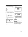
1
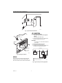
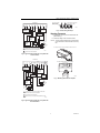
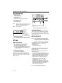
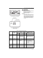
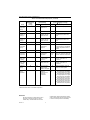
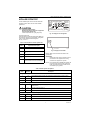
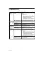
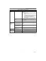
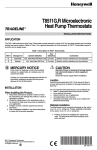
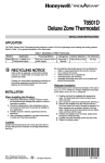
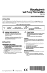
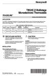
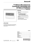
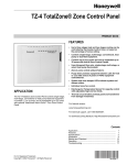
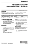
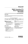
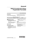
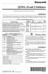
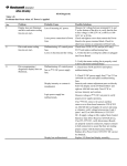
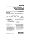
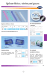
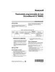
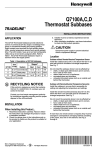
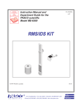
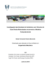
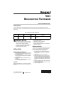
T8501
Microelectronic Thermostats
INSTALLATION INSTRUCTIONS
APPLICATION
The T8501 Microelectronic Thermostats provides electronic control of 24 Vac single-stage heating and cooling
systems. Refer to Table 1 for a general description of the thermostat. All T8501 thermostats require a common wire to
supply power.
Table 1. Description of T8501 Thermostats.
System
Changeover
System Selection
Fan
Selection
Heat-Cool
Automatic
Heat-Off-Cool-Auto
On-Auto
MERCURY NOTICE
If this control is replacing a control that contains
mercury in a sealed tube, do not place your old
control in the trash. Dispose of properly.
Contact your local waste management authority
for instructions regarding recycling and the
proper disposal of the old control.
When Installing this Product...
2.
3.
4.
Read these instructions carefully. Failure to follow
the instructions can damage the product or cause
a hazardous condition.
Check the ratings given in the instructions and on
the product to make sure the product is suitable for
your application.
Installer must be a trained, experienced service
technician.
After completing installation, use these instructions
to check out the product operation.
Location
Install the thermostat about 1.5m (5 ft) above the floor in
an area with good air circulation at average temperature.
See Fig. 1.
® U.S. Registered Trademark
Copyright © 2004 Honeywell •
Do not install the thermostat where it can be affected by:
— drafts, or dead spots behind doors and in corners.
— hot or cold air from ducts.
— radiant heat from sun or appliances.
— concealed pipes and chimneys.
— unheated (uncooled) areas such as an outside wall
behind the thermostat.
Wallplate Installation
The thermostat can be mounted horizontally on the wall
or on a 2 in. x 4 in. (50.8 mm x 101.6 mm) wiring box.
Position wallplate horizontally on the wall or on a
2 in. x 4 in. (50.8 mm x 101.6 mm) wiring box.
INSTALLATION
1.
Comments
System and fan selections are done by
keyboard.
• All Rights Reserved
1.
2.
3.
4.
5.
6.
Position and level the wallplate (for appearance
only). The thermostat will function properly even
when not level.
Use a pencil to mark the mounting holes.
See Fig. 2.
Remove the wallplate from the wall and drill two
3/16 inch (76 mm) holes in the wall (if drywall) as
marked. For firmer material such as plaster, drill
two 7/32 inch (5.56 mm) holes. Gently tap anchors
(provided) into the drilled holes until flush with the
wall.
Position the wallplate over the holes, pulling wires
through the wiring opening.
Loosely insert the mounting screws into the holes.
Tighten mounting screws.
69-0925-4
T8501 MICROELECTRONIC THERMOSTATS
NO
YES
NO
5 FEET
[1.5 METERS]
NO
M10106
Fig. 1. Typical location of thermostat.
CAUTION
Electrical Shock Hazard.
Can cause electrical shock and equipment
damage.
Disconnect power before wiring.
WALL
WIRES
THROUGH WALL
1.
Loosen the terminal screws on the wallplate and
connect the system wires. See Fig. 6.
IMPORTANT
Use 18 gauge, color-coded thermostat cable for
proper wiring.
WALL
ANCHORS
(2)
2.
3.
4.
Securely tighten each terminal screw.
Push excess wire back into the hole.
Plug the hole with nonflammable insulation to prevent drafts from affecting the thermostat.
MOUNTING
HOLES
THERMOSTAT
OT
OT
C
W
R
2
MOUNTING
SCREWS
OUTDOOR
TEMPERATURE
SENSOR
M6530A
HEATING
RELAY OR
VALVE COIL
Fig. 2. Mounting the wallplate.
1
L1
(HOT)
WIRING
L2
All wiring must comply with local electrical codes and
ordinances. Refer to Fig. 3 and 5 for typical hookup. A
letter code is located near each terminal for identification.
1
POWER SUPPLY. PROVIDE DISCONNECT MEANS AND
OVERLOAD PROTECTION AS REQUIRED.
2
AVAILABLE ON SELECT MODELS.
M4822
Fig. 3. Typical hookup in heat only application.
69-0925—4
2
T8501 MICROELECTRONIC THERMOSTATS
.
FOR WRAPAROUND
INSERTION STRIP
7/16 IN. (11 MM).
THERMOSTAT
OT
OT
C
B
O
G
Y
R
W
FOR STRAIGHT INSERTION
STRIP 5/16 IN. (8 MM).
2
M4826
HEATING
RELAY OR
VALVE COIL
OUTDOOR
TEMPERATURE
SENSOR
Fig. 6. Correct wiring technique.
Mounting Thermostat
COMPRESSOR
CONTACTOR
1.
COOL
CHANGEOVER
VALVE OR
DAMPER
HEAT
CHANGEOVER
VALVE OR
DAMPER
2.
FAN
RELAY
Engage tabs at the top of the thermostat and wallplate. See Fig. 7.
Press lower edge of case to close and latch.
NOTE: To remove the thermostat from the wall, first pull
out at the bottom of the thermostat; remove top
last.
1
L1
(HOT)
L2
A. ENGAGE TABS AT TOP OF THERMOSTAT AND WALLPLATE.
1
POWER SUPPLY. PROVIDE DISCONNECT MEANS AND
OVERLOAD PROTECTION AS REQUIRED.
2
AVAILABLE ON SELECT MODELS.
M4821
Fig. 4. Typical hookup in heat and cool system with
one transformer.
THERMOSTAT
3
OT
OT
Rc
O
G
Y
C
B
B. PRESS LOWER EDGE OF CASE TO LATCH.
Rh
W
2
OUTDOOR
TEMPERATURE
SENSOR
HEAT
CHANGEOVER
VALVE OR
DAMPER
COMPRESSOR
CONTACTOR
HEATING
RELAY OR
VALVE COIL
M6798A
FAN
RELAY
COOL
CHANGEOVER
VALVE OR
DAMPER
Fig. 7. Mounting thermostat on wallplate.
1
L1
(HOT)
L2
1
L1
(HOT)
L2
1
POWER SUPPLY. PROVIDE DISCONNECT MEANS AND
OVERLOAD PROTECTION AS REQUIRED.
2
AVAILABLE ON SELECT MODELS.
3
JUMPER Rh TO Rc IN A SINGLE TRANSFORMER SYSTEM.
M4820
Fig. 5. Typical hookup in heat and cool system with
two transformers.
3
69-0925—4
T8501 MICROELECTRONIC THERMOSTATS
Using Thermostat Keys
The thermostat keys are used to:
• set the temperature,
• display present setting,
• configure Installer Setup,
• check System-Test,
• display outdoor temperature (select models),
i
System
System
Select models have keys to:
• set the system operation,
• set the fan operation.
Fan
Press to select
heating or cooling
equipment.
Press to select
heating or cooling
equipment.
Em. Ht.-Emergency heating
HeatÑ Heating equipment
Off Ñ No equipment
CoolÑCooling equipment
AutoÑ Thermostat
automatically selects
heating and cooling
equipment.
OnÑ Fan runs continuously
AutoÑ Fan runs when
heating or cooling
equipment operates
System
Fan
Fan
1
NOTE: Always press the keys with your fingertip or similar blunt tool. Sharp instruments like a pen or
pencil point can damage the keyboard.
1
LED INDICATOR.
M10147C
See Fig. 8 for key locations.
Fig. 9. T8501 System and Fan key locations.
Temperature Settings
INCREASE
TEMPERATURE
SETTING
i
The default setpoint for heat is 70°F (21°C) and for cool
is 78°F (25.5°C). Press the increase ! or decrease #
key to change the present setting. To change between
heat and cool, press the Information i key until the setting
to be changed appears.
DECREASE
TEMPERATURE
SETTING
DISPLAY PRESENT
SETTINGS AND SCROLL
THROUGH INSTALLER
SETUP (INFORMATION KEY)
INSTALLER SETUP
M6801A
Fig. 8. Thermostat key locations and descriptions.
NOTE: For most applications, the thermostat factorysettings do not need to be changed. Review the
factory settings in Table 2 and if no changes are
necessary, go to the Installer Self-Test section.
SETTINGS
The Installer Setup is used to customize the thermostat
to specific systems. Some of the options include:
— temperature display,
— changeover and
— outdoor temperature display.
System and Fan Settings
System settings control the thermostat operation:
Heat: The thermostat controls the heating.
Off: Both the heating and cooling are off.
Cool: The thermostat controls the cooling.
Auto: The thermostat automatically changes between
heating and cooling operation, depending on the
indoor temperature.
Installer Setup numbers are listed in Table 3. The table
includes all the configuration options and the factorysettings for the T8501.
Fan settings control the system fan:
On: Fan operates continuously.
Auto: Fan operates with equipment.
A combination of key presses are required to use the
Installer Setup feature:
— To enter the Installer Setup, press and hold the
information i key with the increase ! and decrease #
keys until the first number is displayed. All display
segments appear for approximately three seconds
before the number is displayed. See Fig. 11 and 12.
— To advance to the next Installer Setup, press the
i key.
— To change a setting, use the increase ! or
decrease # key.
— To exit the Installer Setup, press and hold the
Information i key until the display returns to normal
(approximately three seconds). The display scrolls the
numbers backward to get to the normal display. The
Installer Setup is automatically exited if no key
presses are made for five minutes.
The system default setting is Heat and the fan default
setting is Auto. Use the keyboard or System and Fan
switches, depending on model, to change to the desired
settings. See Fig. 9.
NOTE: Only configurable number are shown.
69-0925—4
4
T8501 MICROELECTRONIC THERMOSTATS
CAUTION
Remote
Room
%Humid
Outdoor
Em Ht Temporary Setting
Aux Ht
Equipment Damage Hazard.
Heat pump and electric heat systems can be
damaged when run without fan.
Configure to 01 in Installer Setup number 02 to
prevent equipment damage.
Repl
Wait
Heat Cool
Batt
System
Fan
Em HeatOffCool Auto Only OnAuto
IMPORTANT
Only configurable numbers are shown on the
device. Example: If thermostat does not have a
system key, Installer Setup Number 12 does not
display. Review Table 3 factory-settings and
mark any desired changes in the Actual Setting
column. When Installer Setup is complete,
review the settings to confirm that they match
the system.
M4844
Fig. 10. Display of all LCD segments.
.
INSTALLER SETUP
NUMBER DISPLAY
(COLUMN 1 OF TABLE 2)
FACTORY SETTING OR
OTHER CHOICE DISPLAY
(COLUMN 3 OR 5 OF TABLE 2)
M10105B
Fig. 11. Display of Installer Setup
number and setting.
Table 2. Thermostat Installer Setup Options.
Installer Setup
Number (Press
i key to
change)
Display
Description
Display
Description
Not Used.
01
—
—
—
—
Fan
operationa
02
0
Conventional
applications where
equipment controls
fan operation in heat
mode.
01
Not Used.
03
—
—
—
Heating cycle
rate.
04
6
05 thru 11
—
—
—
Changeover
(T8501D
only)
12
01
Manual changeover
00
Not used
13
—
—
—
Select
Not Used.
Other Choices
(Press ! or # key to change)
Factory Setting
6 cph used for
conventional
systems
5
01, 03
or 09
Heat pump or electric heat
applications where thermostat
controls fan operation in heat
mode.
—
01—1 cph used for radiant floor
heat, gravity system
03—3 cph used for hot water
systems or high efficiency
furnaces
09—9 cph used for electric heat
systems
—
00—Auto changeover
—
69-0925—4
T8501 MICROELECTRONIC THERMOSTATS
Table 2. Thermostat Installer Setup Options. (Continued)
Select
Degree
temperature
display
Not Used.
Installer Setup
Number (Press
i key to
change)
Display
14
00
Other Choices
(Press ! or # key to change)
Factory Setting
Description
Temperature is
displayed in °F
01
—
Description
Temperature is displayed in °C
15 thru 18
—
Extended fan
operation in
heating.a,b
19
00
No extended fan
operation after the
call for heat ends.
01
Fan operation is extended 90
seconds after the call for heat
ends.
Extended fan
operation in
cooling.a
20
00
No extended fan
operation after the
call for cool ends.
01
Fan operation is extended 90
seconds after the call for cool
ends.
Not Used.
—
Display
21 thru 23
—
24
00
25 thru 32
—
—
Minimum off
time for the
compressor.
33
05
5 minutes minimum
off time for the
compressor.
00, 01,
02, 03
or 04
Minimum number of minutes (0
thru 5) the compressor will be off
between calls for the compressor.
Temperature
range stops
in heating.
34
90
Heating setpoint can
be set no higher
than 90°F.
40 to 90
Number can be set anywhere
between 40 and 90 in 1°F
increments.
Temperature
range stops
in cooling.
35
45c
Lowest setpoint
cooling can be set
to.
45 to 99
Number can be set anywhere
between 45 and 99 in 1°F
increments.
System On
display.a
36
00
LCD On symbol is
displayed when
system is energized.
01
Display is disabled, usually set
for 01 for a zoned system.
Temperature
display
adjustment.
37
00
No difference in
displayed
temperature and
actual room
temperature.
Outdoor
temperature
displaya
Not Used.
aAvailable
bMode
—
—
No outdoor
temperature is
displayed.
—
—
01
Outdoor temperature is
displayed. Needs a C7089B1000
Outdoor Temperature Sensor to
operate.
—
—
+3 thru
03
01—Display adjusts to 1°F higher
than actual room temperature.
02—Display adjusts to 2°F higher
than actual room temperature.
03—Display adjusts to 3°F higher
than actual room temperature.
-1—Display adjusts to 1°F lower
than actual room temperature.
-2—Display adjusts to 2°F lower
than actual room temperature.
-3—Display adjusts to 3°F lower
than actual room temperature.
on select models.
02 must be set to 01 to extend fan operation.
IMPORTANT
Review the settings to confirm that they match
the system. Press Run Program to exit the
Installer Setup. The thermostat has saved the
69-0925—4
Installer Setup changes and initiated a reset in
order to operate using the new settings. Be sure
to set the current day and time immediately.
6
T8501 MICROELECTRONIC THERMOSTATS
INSTALLER SYSTEM TEST
Em Ht Temporary Setting
Aux Ht
Use the Installer System Test to check the thermostat
operation. Refer to Table 3 for a list of the available
system tests.
Remote
Room
%Humid
Outdoor
Repl
Wait
Heat Cool
Batt
System
Fan
Em HeatOffCool Auto Only OnAuto
CAUTION
Equipment Damage Hazard.
Minimum off time for compressor is bypassed
during Installer System Test.
Prevent compressor from cycling too quickly.
M4844
Fig. 12. Display of all LCD segments.
To start the system test:
Press and hold the increase ! and decrease # keys at
the same time until two zeros (00) appear. All segments
of the LCD are displayed before 00 appears.
See Fig. 11 and 12.
Table 3. Tests Available In Installer System Test.
Test
Number
10-19
System Test Description
Heating equipment can be turned on and
off.
30-39
Cooling equipment can be turned on and
off.
40-49
Fan equipment can be turned on and off.
60 0 to
60 19
Keyboard keys test.
70-79
Thermostat information including date
code and software versions are displayed.
TEST NUMBER
M6792A
Fig. 13. Display of test number.
Refer to Table 4 for the directions and results of the
specific tests.
IMPORTANT
Models with System and Fan switches must set
the switches to the equipment that is being
checked for the equipment to operate.
NOTE: Press and hold the increase ! and decrease #
keys for three seconds to exit the system test
mode. The system test times out after five minutes without any key presses.
Table 4. Installer System-Test Options.
Keys to
Press
Test
Number
Description
Heating Equipment System-Test
i
10
Enter heating equipment system-test. (Set System switch to Heat on switch models.)
!
11
Heat comes on. When Installer Setup number 02 is 01, the system fan is also energized.
#
10
Heat and system fan turn off.
Cooling Equipment System Test
i
30
Change from heating to cooling equipment system test. (Set system switch to Cool on
switch models.)
!
31
Cool and system fan come on.
#
30
Cool and system fan turn off.
Fan Equipment System Test (T8501D only)
i
40
Change from cooling to fan equipment system-test.
!
41
Fan comes on.
#
40
Fan turns off.
7
69-0925—4
T8501 MICROELECTRONIC THERMOSTATS
Table 4. Installer System-Test Options. (Continued)
Keys to
Press
Test
Number
Description
System-Testa
Key or Switch Operation
IMPORTANT
Test numbers are displayed only when the system is configured for the selected function.
Example: Numbers 60, 61 and 62 are the only numbers that are displayed when a system is configured for
heat only.
System Key or Switch System Test (When System switch is used, move switch to see Test Numbers.)
60
Change from cooling or fan to key operation system test.
System
i
61
Heat test number is displayed. (Set System switch to Heat.)
System
62
Off test number is displayed. (Set System switch to Off)
System
63
Cool test number is displayed. (Set System switch to Cool.)
System
64
Auto Test number is displayed.
Fan Key System Test (Fan switch cannot be tested)
Fan
68
Fan
69
a
Available on select models.
69-0925—4
8
T8501 MICROELECTRONIC THERMOSTATS
THERMOSTAT INFORMATION
1.
4.
Press the increase ! key again to display the software revision number (Example: 001 = revision
number 1).
5.
Press the increase ! key again to display the
EEPROM identification code. (Example: 222 =
EEPROM ID 222.)
6.
Press and hold the increase ! and decrease #
keys together, until the room temperature is displayed, to exit the system test mode. The system
test times out after five minutes without any key
presses.
Press the i key to access the thermostat information.
M6791
M4864
2.
Press the increase ! key to display the production
date code. The first two large digits are the month
and the third digit is the last digit of the year (Example: 026 = February 1996).
M4867
M4865
3.
Press the increase ! key again to display the software identification code. (Example: 02 = software
ID code 2).
CHECKOUT
Outdoor Temperature Sensor
(Select Models)
Allow the outdoor temperature sensor to take in the
outdoor air for a minimum of five minutes before taking a
reading. With an accurate thermometer ±1°F (±0.5°C),
measure the temperature at the sensor location, allowing
time for the thermometer to stabilize before reading.
Match the thermometer reading to the outdoor
temperature display at the thermostat.
M4866
9
69-0925—4
T8501 MICROELECTRONIC THERMOSTATS
TROUBLESHOOTING GUIDE
Table 5. Troubleshooting Guide.
Symptom
Display will not
come on.
Possible Cause
Action
Thermostat is not being
powered.l
• Check that C terminal is connected to the system
transformer.
• Check for 24 Vac between C and R or RH terminals.
— If missing 24 Vac:
— check if the circuit breaker is tripped—reset the circuit
breaker.
— check if the system fuse is blown—replace the fuse.
— check if the power switch on the HVAC equipment is in
the Off position—set to the On position.
— check wiring between thermostat and HVAC
equipment—replace any broken wires and tighten any
loose connections.
— If 24 Vac is present, proceed with troubleshooting.
Thermostat microprocessor is
locked up.
Remove the thermostat from the wallplate for two minutes. After
two minutes, replace the thermostat on the wallplate.
Temperature
Room temperature display has
display is incorrect. been reconfigured.
Enter Installer Setup number 37 and reconfigure the display.
Thermostat is configured for °F
or °C display.
Enter Installer Setup number 14 and reconfigure the display.
Bad thermostat location.
Relocate the thermostat.
Temperature
settings will not
change. (Example:
Cannot set the
heating higher or
the cooling lower.)
The upper or lower temperature Check the temperature setpoints:
limits were reached.
• Heating limits are 40 to 90°F (4.5 to 32°C)
• Cooling limits are 45 to 99°F (7 to 37°C).
Heating will not
come on.
No power to the thermostat.
The setpoint temperature range Check Installer Setup numbers 34 and 35 and reconfigure the
stops were configured.
setpoint stops.
• Check that C terminal is connected to the system
transformer.
• Check for 24 Vac between C and R or RH terminals.
— If missing 24 Vac:
— check if the circuit breaker is tripped—reset the circuit
breaker.
— check if the system fuse is blown—replace the fuse.
— check if the System switch on the HVAC equipment is
in the Off position—set to the On position.
— check wiring between thermostat and HVAC
equipment—replace any broken wires and tighten any
loose connections.
— If 24 Vac is present, proceed with troubleshooting.
Thermostat minimum off time is Wait up to five minutes for the system to respond.
activated.
System selection is not set to
Heat.
69-0925—4
Set system selection to Heat.
10
T8501 MICROELECTRONIC THERMOSTATS
Table 5. Troubleshooting Guide. (Continued)
Symptom
Cooling will not
come on.
System on indicator
is displayed, but no
heat is being
delivered.
Possible Cause
Action
No power to the thermostat.
• Check that C terminal is connected to the system
transformer.
• Check for 24 Vac between C and R or RC and Y terminals.
— If missing 24 Vac:
— check if the circuit breaker is tripped—reset the circuit
breaker.
— check if the system fuse is blown—replace the fuse.
— check if the power switch on the HVAC equipment is in
the Off position—set to the On position.
— check wiring between thermostat and HVAC
equipment—replace any broken wires and tighten any
loose connections.
— If 24 Vac is present, proceed with troubleshooting.
Thermostat minimum off time is
activated.
• Wait up to five minutes for the system to respond.
• Enter Installer Setup number 33. Reconfigure minimum off
time (if required).
System selection is not set to
Cool.
Set system selection to Cool.
Fan operation set for 00
(conventional heat) when it
should be set for 01 (electric
heat).
Enter Installer Setup mode number 02 and reconfigure the fan
operation.
Conventional heating equipment Wait a minute after seeing the On indicator and then check the
turns on the fan when the
registers.
furnace has warmed up to
setpoint.
Outdoor temperature not displayeda
Heating equipment is not
operating.
Verify operation of heating equipment in self-test.
Option not activated.
Enter Installer Setup number 24 and set to 01. Thermostat must
have OT terminals and a C7089B1000 installed.
Outdoor sensor is connected
Outdoor
incorrectly.
temperature
a
display is incorrect Wrong sensor.
Refer to C7089B1000 installation instructions and check wiring
between the thermostat and sensor.
Replace sensor with C7089B1000 sensor.
a
Select Models
11
69-0925—4
T8501 MICROELECTRONIC THERMOSTATS
Automation and Control Solutions
Honeywell
1985 Douglas Drive North
Golden Valley, MN 55422
69-0925—4
Honeywell Limited-Honeywell Limitée
35 Dynamic Drive
Scarborough, Ontario
M1V 4Z9
G.H. Rev. 04-04
www.honeywell.com/yourhome