1
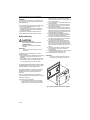
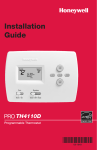
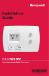
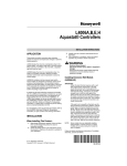
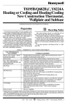
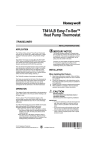
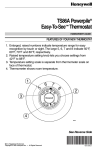
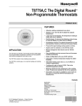
T8034C Heating and
Cooling Thermostat
INSTALLATION INSTRUCTIONS
APPLICATION
The T8034C Thermostat (see Fig. 1) controls 24 to 30 Vac single-stage heating-cooling systems. See Table 1 for
application information. An spdt mercury switch makes R to W on a temperature fall for heating, and R to Y on a
temperature rise for cooling.
Table 1. T8034C Specifications.
Model No.
T8034C1085
MOUNTING HOLE
(THERMOSTAT
TO WALL OR
OUTLET BOX)
Heat
Anticipation
Application
For use in gas- or
oil-fired heating
systems.
BIMETAL ELEMENT
BEHIND HEAT
ANTICIPATOR
SCALE
0.18A to 1.0A,
adjustable.
SYSTEM
SWITCH
Switching
System
Heat-OffCool
Fan
On-Auto
Comments
See Fig.
No.
TRADELINE®
3
MERCURY NOTICE
If this control is replacing a control that contains
mercury in a sealed tube, do not place your old
control in the trash. Dispose of properly.
MOUNTING
HOLE
Contact your local waste management authority
for instructions regarding recycling and the
proper disposal of an old control.
.2
.18
.9
.7
.5
.25 L
INSTALLATION
ONG
.35
.3
When Installing This Product . . .
1.
ADJUSTABLE HEAT
ANTICIPATOR INDICATOR
FAN
SWITCH
TEMPERATURE
SETTING LEVER
M5601
Fig. 1. T8034C internal view.
2.
3.
4.
® U.S. Registered Trademark
Copyright © 2001 Honeywell •
• All Rights Reserved
Read these instructions carefully. Failure to follow
them could damage the product or cause a hazardous condition.
Check the ratings given in the instructions and on
the product to make sure the product is suitable for
your application.
Installer must be a trained, experienced service
technician.
After installation is complete, check out the product
operation as provided in these instructions.
69-1596
T8034C HEATING AND COOLING THERMOSTAT
Location
Locate the thermostat about 5 ft (1.5m) above the floor
on an inside wall in an area with good air circulation at
average temperature.
2.
3.
Do not mount the thermostat where it can be affected by:
— drafts or dead spots behind doors or in corner.
— hot or cold air from ducts.
— radiant heat from the sun, fireplaces or appliances.
— unheated (uncooled) areas such as outside walls
behind the thermostats.
This thermostat is a precision instrument and was
carefully adjusted at the factory. Handle it carefully.
4.
5.
Wiring and Mounting
6.
CAUTION
7.
Electrical Shock Hazard.
Can cause personal electrical shock and
equipment damage.
Disconnect power supply before beginning
installation.
8.
IMPORTANT
All wiring must comply with local codes and
ordinances.
9.
10.
The T8034C can be mounted directly on a wall or
horizontal outlet box:
— Use the 200581 (beige) or 202895A (gray) Horizontal
Wallplate to cover mounting marks from an old
thermostat.
— Use the 19312A (beige) or 202689A (gray) Mounting
Plate Assembly to mount on vertical outlet box or to
cover wall marks where larger plate is needed.
plastered into the wall, make a hole next to the
wires and loosen the wires so they can be pushed
back into the wall later.
In new installations, run wiring (if necessary) to the
thermostat location.
Connect the wires to the terminals on the back of
the thermostat. See Fig. 3 for internal schematic
and typical hookup diagram.
Remove thermostat cover by pulling outward on
right edge of cover until it snaps free of the thermostat base. Carefully remove and discard the foam
plastic shipping insert that protects the switch and
bimetal assembly during shipping.
Set the adjustable heat anticipator indicator to
match the current draw of the primary heating control (see Heat Anticipator Setting section).
Push excess wire back through the hole and plug
any opening with insulation to prevent drafts that
can affect thermostat performance.
Loosely fasten the thermostat (with wallplate, if
applicable) to the wall or outlet box with a screw
through the left mounting hole. Adjust the thermostat so it is approximately level and fasten the second screw through the right mounting hole. Do not
tighten.
For optimum performance, level the thermostat
using a spirit level or plumb line. Tighten the
mounting screws.
Adjust temperature setting lever so mercury bulb is
in horizontal position as shown in Fig. 2.
Carefully replace the thermostat cover.
IMPORTANT
An incorrectly leveled thermostat causes the
temperature control to deviate from setpoint.
The SUPER TRADELINE® T8034C includes the 200581
Horizontal Wallplate. For other T8043C models, order the
horizontal wallplate or mounting plate assembly.
UP
If the horizontal wallplate is used, align the thermostat
and wallplate. See Fig. 2. Press firmly together until
wallplate snaps in place, then wire and mount the
thermostat.
ol
Co
Off
at
He
If the mounting plate assembly is used, review the
instructions provided with the assembly before wiring and
mounting the thermostat.
90
80
70
60
To wire and mount the thermostat:
1. In replacement applications, check the existing
thermostat wires for cracked or frayed insulation.
Replace any wires in poor condition. If the wire is
Au
to
N
FA
On
M20287
Fig. 2. Mounting T8034C Thermostat on wallplate.
69-1596
2
T8034C HEATING AND COOLING THERMOSTAT
L1
(HOT)
L2
RC
FAN SWITCH
FAN RELAY
H1
ON
C1
1
G
TEMP. FALL
AUTO
H1
ANTICIPATOR
Y
COOL RELAY
C1
ANTICIPATOR
2
SYSTEM
SWITCH
COOL
RH
HEAT
OFF
OFF
1
POWER SUPPLY. PROVIDE DISCONNECT MEANS AND
OVERLOAD PROTECTION AS REQUIRED.
2
IN SINGLE TRANSFORMER SYSTEMS, JUMP RC AND RH.
1
COOL
HEAT
HEAT RELAY
W
L1
(HOT)
L2
M2043C
Fig. 3. Internal schematic and typical hookup for T8034C1085 in dual-transformer heating-cooling systems.
SETTINGS AND ADJUSTMENTS
Look for the current rating stamped on the nameplate of
the primary control. Set the adjustable heat anticipator
indicator to match the value shown on the nameplate.
Temperature Setting
If the current rating is not available, proceed as follows to
determine the rating:
1. Turn off the power.
2. Wire the thermostat, but do not mount it on the
wall.
3. Connect the ammeter between the W wire and the
W terminal on the thermostat (in series with the primary control).
4. Prepare the system for operation.
5. Turn on the power.
6. Turn the System switch to Heat.
7. Increase the thermostat setpoint, as necessary, to
begin operating the system.
8. With the system operating through the ammeter,
wait one minute, then read the ammeter.
9. Turn the System switch to Off and turn off the
power.
10. Adjust the heat anticipator to match the ammeter
reading.
11. Disconnect the ammeter, reconnect the W wire,
and mount the thermostat.
Push the temperature setting lever to the desired control
point on the temperature scale. The same lever controls
the temperature setting for either heating or cooling.
System and Fan Switching
The T8034C has System and Fan switches to control the
heating-cooling systems and fan.
The System switch controls system operation:
Heat: Operates only heating system.
Off: Both heating and cooling systems are disconnected.
Cool: Operates only cooling system.
The Fan switch controls fan operation:
Auto: For gas-or oil-fired systems; the fan operates in
response to the thermostat in cooling and in
response to the plenum fan control in heating. For
electric heat or heat pump systems, the fan operates in response to the thermostat in both heating
and cooling.
On: The fan runs continuously.
NOTE: For best performance, the heat anticipator may
require further adjustment. To lengthen burneron time, move the indicator in the direction of
the longer arrows but not more than one-half
scale marking at one time. To shorten burner-on
time, move the indicator in the opposite direction.
To switch positions, use thumb and index finger to slide
lever to desired position. Stop switch lever in detent
directly over desired position. Stop switch lever in detent
directly over desired function indicator mark for correct
circuit operation.
CHECKOUT
Heat Anticipator Setting
IMPORTANT
The T8034C Thermostat has an adjustable heat
anticipator and operates correctly only if the
anticipator is adjusted to match the current draw
of the primary control. Use this thermostat only
on systems with current draw that falls within
the range of the heat anticipator. Do not use this
device on Powerpile® Systems (millivolt).
CAUTION
Equipment Damage Hazard.
Heat anticipator can be damaged.
Do not check operation by shorting across
system control terminals.
IMPORTANT
To assure accurate temperature control, do not
touch or breathe on bimetal or thermometer.
3
69-1596
T8034C HEATING AND COOLING THERMOSTAT
Heating
With System switch set at Heat, and Fan switch set at
Auto, move the temperature setting lever about 10°F
(6°C) above room temperature:
Gas or oil-fired systems: heating should start; fan
should start after a short delay.
Central electric heat or heat pump systems: both
heating and fan should start.
Move the temperature setting lever about 10°F (6°C)
below room temperature:
Gas or oil-fired systems: heating should shut off and
fan should shut off after a short delay.
Electric heat or heat pump systems: heating and fan
should shut off.
Cooling
CAUTION
Equipment Damage Hazard.
Air conditioning equipment (compressor) can
be damaged.
Do not operate cooling when outdoor
temperature is below 50°F (10°C). Refer to
manufacturer’s recommendations.
IMPORTANT
To prevent compressor short cycling, some
manufacturer’s equipment includes a minimumoff timer to provide a five-minute time delay
from when the thermostat last turned off the
compressor, or from when the system first
received power. This delay protects the compressor.
WIth the System switch set at Cool and the Fan switch
set to Auto, move the temperature setting lever about
10°F (6°C) below room temperature. Cooling and fan
should start (see Important above). Move the
temperature setting lever about 10°F (6°C) above room
temperature. Cooling and fan should shut off.
To check calibration:
1. Move the temperature setting lever to the lower
end of the temperature scale. Place the System
switch to the Off position. Wait at least five minutes.
2. Remove the thermostat cover. Move the setting
lever until the switch just makes contact. (The mercury in the switch rolls to the left end of the tube.)
3. Replace the cover and wait five minutes for the
cover and the thermostat to lose the heat it has
gained from your hands. If the thermometer pointer
and the setting lever indicator read approximately
the same, no recalibration is needed.
If recalibration appears necessary:
1. Place the temperature setting lever at the same
setting as the thermometer. Remove the cover by
pulling out on the right edge of the cover until it
snaps free of the thermostat base.
2. Insert the 104994A Calibration Wrench (ordered
separately) onto the hex nut under the coil. (See
Fig. 4.) Holding the setting lever so it does not
move, turn the wrench clockwise until the mercury
rolls to the right end of the tube. Remove the
wrench and replace the cover.
IMPORTANT
To assure accurate temperature control, do not
touch or breathe on bimetal or thermometer.
3.
4.
5.
6.
7.
8.
Move the setting lever to a lower setting. Wait at
least five minutes for the temperature to stabilize.
Slowly move the setting lever until it reads the
same as the thermometer.
Remove the cover. Holding the setting lever so it
does not move, reinsert the wrench and carefully
turn it counterclockwise just until the mercury rolls
to the left end of the tube but no farther.
Recheck the calibration. Set the thermostat System switch for the desired operation.
Adjust the temperature setting lever so the mercury
bulb is in position as shown in Fig. 4.
Carefully replace the thermostat cover.
Fan
With the System switch set to Off and the Fan switch set
to On, the fan should run continuously. Move the Fan
switch to Auto. In gas- or oil-fired systems, fan operation
is controlled by the plenum fan control in heating and by
the thermostat in cooling. In central electric heat and heat
pump systems, fan operation is controlled by the
thermostat in both heating and cooling.
COIL SHOWN WITHOUT
HEAT ANTICIPATOR
Recalibration
CALIBRATION
WRENCH
These thermostats are calibrated at the factory and
should not need recalibration. If the thermostat seems
out of adjustment, first check for accurate leveling.
M2044A
Fig. 4. Recalibrating the thermostat.
$XWRPDWLRQDQG&RQWURO6ROXWLRQV $XWRPDWLRQDQG&RQWURO6ROXWLRQV
+RQH\ZHOO
'RXJODV'ULYH1RUWK
*ROGHQ9DOOH\01
69-1596 G.H. 12-01
+RQH\ZHOO/LPLWHG+RQH\ZHOO/LPLWpH
'\QDPLF'ULYH
6FDUERURXJK2QWDULR
09=
Printed in U.S.A. on recycled
paper containing at least 10%
post-consumer paper fibers.
www.honeywell.com/yourhome