1
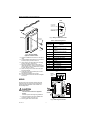
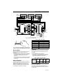
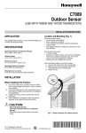
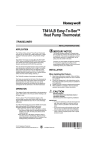
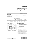
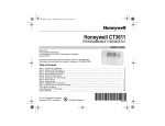
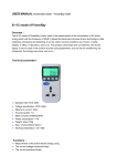
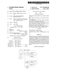
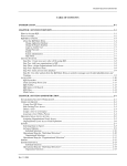
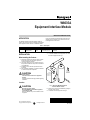
W8635A Equipment Interface Module INSTALLATION INSTRUCTIONS APPLICATION tronic Communicating Programmable Thermostat. The W8635A can be used with up to 2 heat/2 cool conventional applications. See Table 1. The W8635A Equipment Interface Module (EIM) provides 24 Vac control of single or multistage conventional HVAC equipment when used with a T8635L Microelec- Table 1. Description. Model W8635A Application Conventional gas, oil or electric heat Stages Terminals Comments Up to 2 heat/ 1, 2, 3, C, R, Rh, Rc, 2 cool G, W1, W2, Y1, Y2 INSTALLATION 1. Use with T8635L Communicating Thermostat Locate the W8635A in the equipment room near the HVAC equipment. See Fig. 1. When Installing this Product… 1. 2. 3. 4. Read these instructions carefully. Failure to follow these instructions can damage the product or cause a hazardous condition. Check the ratings given in the instructions and on the product to make sure the product is suitable for your application. Installer must be a trained, experienced service technician. After completing installation, use these instructions to check out the product operation. CAUTION Voltage Hazard. Can cause electrical shock or equipment damage. Disconnect power before supply before beginning installation. Location FURNACE OR BOILER WATER HEATER M16637A Fig. 1. Selecting W8635A Equipment Interface Module location. CAUTION Mounting Location Hazard. Mounting W8635A inside HVAC equipment can damage the EIM. Mount the W8635A only on the outside of HVAC equipment. ® U.S. Registered Trademark Copyright © 2000 Honeywell Inc. • W8635 POSSIBLE MOUNTING LOCATION W8635 POSSIBLE MOUNTING LOCATION • All Rights Reserved 2. 3. Remove the cover from the W8635A by pulling on the edge of the module. Locate the two mounting holes. See Fig. 2. 69- 1339- 2 W8635A EQUIPMENT INTERFACE MODULE W8635 WALL FOR STRAIGHT CONNECTION— STRIP 5/16 IN. (8 MM) W8635 FOR WRAPAROUND CONNECTION— STRIP 7/16 IN. (11 MM) M16639 MOUNTING HOLES (2) 1 2 G 3 W1 W2 C Y1 Y2 R Fig. 3. Wiring the W8635A terminals. MOUNTING SCREWS (2) Table 2. Terminal Designations. W8635A Terminal Designations RH RC M16636 Fig. 2. Mounting W8635A Equipment Interface Module. Position the W8635A on the wall or on the cold air return. 5. Level the W8635A for appearance only; the device functions properly even when not level. 6. Use a pencil to mark the position of the mounting holes on the wall or cold air return. 7. Remove the W8635A from the wall or cold air return and drill 3/16 in. holes in the wall (if drywall) where marked. For firmer materials such as plaster or wood, drill 7/32 in. holes. 8. When mounting on the cold air return, drill a pilot hole where marked. 9. Gently tap the anchors (provided) into the holes until flush with the wall. 10. Reposition the W8635A over the holes. 11. Loosely insert the screws into the holes and tighten each screw. 4. Function 1 To Communicating Thermostat Terminal 1 2 To Communicating Thermostat Terminal 2 3 To Communicating Thermostat Terminal 3 R 24 Vac System Transformer Rh 24 Vac Heating Transformer Rc 24 Vac Cooling Transformer C 24 Vac Transformer Common G Fan Relay W1 Stage 1 Heat Relay W2 Stage 2 Heat Relay Y1 Stage 1 Cool Relay Y2 Stage 2 Cool Relay Green LED Indicates Data Communication T8635L C7089B OUTDOOR TEMPERATURE SENSOR WIRING OT HEAT 1 RELAY 3 G L1 (HOT) C W1 R W2 Y1 RH RC Y2 SYSTEM TRANSFORMER HEAT 2 RELAY COOL 1 RELAY COOL 2 RELAY 1 Loosen the terminal screws on the W8635A and connect the system wires. See Fig. 3. Securely tighten each terminal screw. 69-1339—2 FAN RELAY 2 CAUTION 2. 3 1 L2 1. 2 1 W8635A All wiring must comply with local electrical codes and ordinances. See Fig. 4 through 6 wiring diagrams for specific equipment applications. Refer to Table 2 for terminal designations. Voltage Hazard. Can cause electrical shock or equipment damage. Disconnect power before beginning installation. OT 1 FACTORY INSTALLER JUMPERS. Fig. 4. 2H/2C single transformer. 2 M13429 W8635A EQUIPMENT INTERFACE MODULE T8635L T8635L C7089B OUTDOOR TEMPERATURE SENSOR OT OT 2 1 OT 3 T8635L OT 2 1 OT 3 W8635A 3 6 Z 2 3 X OPEN CLOSE G C W1 R W2 Y1 RH RC HEAT 2 RELAY COOL 1 RELAY Y2 SYSTEM TRANSFORMER 4 5 6 Z 1 2 3 X OPEN CLOSE OPEN CLOSE COOL 2 RELAY 1 4 5 6 Z 1 2 3 X ZONE A 5 1 1 ZONE B 4 HEAT 1 RELAY 3 1 2 2 ZONE C FAN RELAY 2 L2 1 W8703A 1 L1 (HOT) OT TR1 TR2 3 L1 (HOT) L2 COM EXTERNAL 40 VA TRANSFORMER FACTORY INSTALLER JUMPERS. OPTIONAL TROL-A-TEMP MODEL ARD-PC OR MODEL ZD TROL-A-TEMP MODEL AOBD ZONE DAMPER M13430A Fig. 5. Three zone configuration. Table 3. Stage Combinations. WIRE NUT M13378 Fig. 6. Using wire nut to pigtail a connection when three or more wires are terminated at one terminal. Discovery Mode Discovery mode begins when the T8635L Thermostat and W8635 EIM are first installed and power is connected: — The W8635 EIM transmits information to the T8635L Thermostat that indicates the maximum number of stages that are enabled and the type of EIM connected. — The thermostat receives information from the W8635 and then sets the cycle rates and equipment types automatically. For configuration combinations, see Table 3. Cool Stages 1 0 2 0 0 1 0 2 1 1 2 2 Cycle Rate The thermostat automatically sets the cycle rate based on the information it received during Discovery Mode. See Table 4. To change the default cycle rate settings: — enter T8635L Thermostat Installer Setup and select the desired cycle rate settings for each stage. (All stages can be set between 1 and 12 cph.) Table 4. Default Cycle Rate Settings. W8635A Equipment Interface Module Stage Configuration The W8635A automatically configures the T8635L for two stages of heat and two stages of cool. If using the W8635A and the T8635L on a one heat/one cool application, set Installer Setup No. 5 and 8 to 1 when configuring the T8635L Communicating Thermostat. Heat Stages 1st Stage Heat 2nd Stage Heat 1st Stage Cool 2nd Stage Cool 6 cph 6 cph 3 cph 3 cph Electric Heat Setting When using the W8635A on an electric heat application, set the T8635L Thermostat Installer Setup No. 4 to 1. This instructs the W8635A EIM to energize the fan with any call for heat. 3 69-1339—2 W8635A EQUIPMENT INTERFACE MODULE Flash COM OK LED Description LED blinks rapidly—indicates device is currently transmitting information on the communications bus. LED blinks once—indicates device received and acknowledged a message. LED on constantly—indicates device failure. Replace device. LED off constantly—indicates a wiring problem if device is not functioning properly and there is no LED activity at least once a minute. Check wiring to communications bus terminals 1, 2 and 3. NOTE: It is normal for LED to blink continuously during startup and discovery. CAUTION Equipment Damage Hazard. Minimum compressor off-time is bypassed during Installer System Test. Do not allow compressor rapid cycling (on and off). Observe compressor protection period. To start the Installer System Test: 1. Press and hold the T8635L Thermostat increase ▲ and decrease ▼ keys at the same time until 10 appears. All display segments display before the 10 appears. See Fig. 7 and 8. LED blinks continuously—indicates a wiring problem if device is not functioning properly and there is a continuous series of LED blinks. Check wiring to communications bus terminals 1, 2 and 3. Set Program Start Time Set Day/Time Temporary Setting Enrg Sav Hold for AM Em Ht Room PM Aux Ht %Humid MonTueWedThuFriSatSun Heat Cool Outdoor WakeLeaveReturnSleep In Recovery Filter Auto Repl Batt System Fan DST On Auto Em Heat OffCool Auto Wait INSTALLER SYSTEM TEST M10345A Fig. 7. LCD segments display. Use the Installer System Test to check the thermostat and W8635A EIM operation for each thermostat in the system. Table 5 lists the available system tests. Table 5. Installer System Tests. Test Number System Test Description 10-12 Heating stages can be turned on and off in sequence 30-32 Cooling stages can be turned on and off in sequence 40-42 Fan and damper test 60 TEST NUMBER Fig. 8. Installer Test Number display. 2. Keyboard keys test 70-74 Refer to Table 6 for Installer System Test option. Thermostat information including date code and software versions are displayed. Table 6. Installer System Test Options. Key to Press Test Number Description Heating Equipment System Test 10 Enter Heating Equipment system test. ▲ 11 First Stage Heat turns on. ▲ 12 Second Stage Heat turns on. ▼ 11 Second Stage Heat turns off. ▼ 10 First Stage Heat turns off. Cooling Equipment System Test 69-1339—2 M10257A 30 Enter Cooling Equipment system test. ▲ 31 First Stage Cool turns on. ▲ 32 Second Stage Cool turns on. ▼ 31 Second Stage Cool turns off. ▼ 30 First Stage Cool turns off. 4 W8635A EQUIPMENT INTERFACE MODULE Table 6. Installer System Test Options. (Continued) Key to Press Test Number Description Fan and Damper Test (Damper Test available only when using W8703A) 40 Enter Fan and Damper test. ▲ 41 Fan turns on; damper for this zone opens. ▲ 42 Damper closes for this zone (if not already closed); fan stays on. ▼ 41 Damper opens for this zone. ▼ 40 Fan turns off. 60 Enter Key Operation test. Key Operation Test Press any key to test if the key is functional. Each time a key is pressed, a different number is displayed. This indicates the key is functioning properly. Pressing enters the next test. Thermostat Information 70 Enter Thermostat Information mode. ▲ 71 Production date code is displayed. The first two large digits are the month and the third digit is the last digit of the year (example: 031 = March 2001). ▲ 72 Software identification code is displayed. ▲ 73 Software revision number is displayed. ▲ 74 EEPROM identification code is displayed. Exit Installer Test Mode Thermostat returns to normal operating mode. Run Program TROUBLESHOOTING GUIDE Refer to Table 7 for troubleshooting information. Table 7. Troubleshooting Guide. Symptom Possible Cause Action Display does not come Thermostat is not being powered. Check if the thermostat is mounted and latched on the on at thermostat. wallplate; if not: —mount and latch the thermostat on the wallplate. Check if the circuit breaker is tripped; if it is: —reset the circuit breaker. Check if the fuse is blown; if it is: —replace the fuse. Check if the power switch at the equipment is in the Off position; if it is: —set to the On position. Check for 24 Vac on terminals 2 and 3: —replace any broken wires. If 24 Vac is present on terminals 2 and 3: replace the thermostat. “1 COM”, “2 COM” or “3 COM” is displayed. Thermostat is unable to communicate with the W8635A. Check the connection to terminal 1 at the thermostat and W8635A EIM: —replace any broken wires. cycle power. System Switch setting displays “off only.” During Discovery Mode, the Manually run Discovery Mode; see Installer Setup. thermostat did not correctly set manually configure heat and/or cool stages the number of heat or cool stages. (Installer Setup 5 and 8). 5 69-1339—2 W8635A EQUIPMENT INTERFACE MODULE Table 7. Troubleshooting Guide. (Continued) Symptom Possible Cause Action Heating does not come Communication is not being on. System on indicator completed. ( = heat) displays. Heat load at W8635A is not connected correctly. End and repeat the call for heat. Check the Flash COM OK LED on the W8635A EIM while the call is being made. If the Flash COM OK LED does not blink: check communication Bus wiring. If the Flash COM OK LED blinks: check that 24 Vac is present at W1 terminal. If 24 Vac is not present: check R to Rh connection. If the connection is good: replace the W8635A EIM. Cooling does not come Communication is not being on. System on indicator completed. ( = cool) displays. Cool load at W8635A is not connected correctly. End and repeat the call for cool. Check the Flash COM OK LED on the W8635A EIM while the call is being made. If the Flash COM OK LED does not blink: check communication bus wiring. If the Flash COM OK LED blinks: check that 24 Vac is present at Y1 terminal. If 24 Vac is not present: check R to Rh to Rc jumper connection. If the R to Rh to Rc connection is good: replace the W8635A EIM. “wait” is displayed and Compressor protection is in the call for Cool has not effect. started. Compressor protection can be set from 0 to 5 minutes to prevent compressor damage due to rapid cycling. Wait until the compressor protection period expires. To bypass compressor protection during the installation phase, see the Installer System Test section. 2nd stage heat or cool does not energize. Set the Stage configuration in Installer Setup for two Stage configuration not set correctly to match the number of stages or heat and/or two stages of cool. selected stages. Cool load at W8635A is not connected correctly. Fan does not come on Electric heat setting is not with a call for electric configured. heat. Fan load at W8635A is not connected correctly. Home and Building Control Honeywell Inc. Honeywell Plaza P.O. Box 524 Minneapolis, MN 55408-0524 69-1339—2 G.H. Rev. 6-00 Check that 24 Vac is present at Y2 or W2 terminal. If 24 Vac is not present, all connections are good and the thermostat is correctly configured, replace W8635A EIM. Set Installer Setup No. 4 to 1 for electric heat. Check that 24 Vac is present at G terminal. If 24 Vac is not present, all connections are good and the thermostat is configured, replace the W8635A EIM. Home and Building Control Honeywell Limited-Honeywell Limitée 155 Gordon Baker Road North York, Ontario M2H 3N7 Printed in U.S.A. on recycled paper containing at least 10% post-consumer paper fibers. www.honeywell.com