1
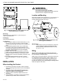
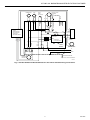
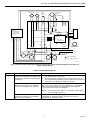
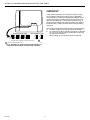
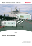
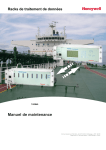
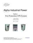
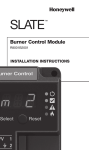
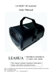
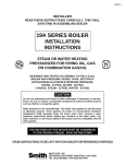
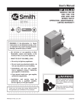
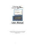
ST7997
Oil Burner Mounted Electric Fan Timer
INSTALLATION INSTRUCTIONS
APPLICATION
Limit:
10A maximum.
The ST7997 Oil Burner Mounted Electric Fan Timer
integrates control of burner and circulator fan operations in
an oil furnace and is the central wiring point for most
electrical components in the furnace. The ST7997 mounts
on a standard four-inch by four-inch junction box typically
located on the oil burner. When used with the R7997
Integrated Oil Primary Controller and Ignitor, it provides
simplified wiring and field serviceability. The basic
purposes of the ST7997 are to monitor the thermostat for
heat, cool and fan demands, run the oil burner primary
control and run a two-speed circulating fan, as required.
The ST7997 also monitors a limit switch string that
energizes the circulating fan when the limit switch opens.
L1/L2 (Burner):
20A maximum.
The ST7997 provides electronic air cleaner (EAC) and
humidifier (HUM) terminal connections for field installation
convenience.
SPECIFICATIONS
Electrical
Input Ratings
Supply Voltage:
102 to 132 Vac (120 Vac nominal), 60 Hz.
Supply Current:
100 mA maximum without loads connected to outputs.
20A maximum with loads connected to outputs.
Output Ratings:
Relay Contacts:
Circulator Heat or Cool Blower Speed Rating: 15A Full
Load Amperage (FLA) (0.75 pF)/30A Locked Rotor
Amperage (LRA) (0.5 pF).
NOTE: FLA rating is reduced by EAC load.
EAC:
1A maximum.
Circulator Continuous Blower Speed Rating:
8A FLA (0.75pF)/16A LRA (0.5pF).
Thermostat Current:
Heat Mode: 100 mA (R7997 supplied).
Cool Mode: Cooling contactor load 500 mA maximum
(ST7997 supplied).
Cooling Contactor:
2 VA minimum, 12 VA maximum.
Molex® is a registered trademark of Molex Incorporated.
Fuse:
1A (automotive type ATO).
Delay Timings:
Heat On Delay: 45 or 60 seconds (fixed or field
selectable via DIP switch optional position 3).
Heat Off Delay: 60/100/120/150 seconds (four field
selections via DIP switch positions 1 and 2).
Cool On/Off Delay: 0/0 or 30/30 seconds (fixed).
Delay Timing Tolerances:
±5 seconds or ±20 percent, whichever is greater.
Environmental
Temperature Ranges:
Operating: -40°F (-40°C) to +150°F (66°C).
Storage: -20°F (-29°C) to +150°F (66°C).
Humidity:
90 percent relative humidity at 95°F (35°C),
noncondensing.
Approvals:
Underwriters Laboratories Inc. Component
Recognized: File 353.
Canadian Underwriters Laboratories inc. Component
Recognized: Pending approval.
Mechanical:
Dimensions (Fig. 1):
4-9/32 in. (109 mm) long by 4-1/4 in. (108 mm) wide by
3-27/32 (97 mm) high. See Fig. 1.
Humidifier:
1A maximum.
Molex® is a registered trademark of Molex Incorporated.
Copyright © 1998 Honeywell Inc. • All Rights Reserved
X-XX UL
69-1204
ST7997 OIL BURNER MOUNTED ELECTRIC FAN TIMER
WARNING
Electrical Shock Hazard
Can cause serious injury or death.
Disconnect power supply before wiring to prevent
electrical shock or equipment damage.
4-1/4
(108)
Location and Mounting
C Y G Rc
Mount the ST7997 on the oil burner 4 in. (102 mm) by 4 in.
(102 mm) junction box compartment using four No. 6
screws (obtained locally). See Fig. 2.
4-9/32 (109)
3-27/32
(97)
R7997
ST7997
M12920
Fig. 1. ST7997A,B Oil Burner Mounted Electric Fan
Timer dimensions in in. (mm).
BURNER
Mounting:
Mounts directly on standard 4 in. (102 mm) by 4 in.
(102 mm) junction box.
Packaging:
Unit pack and bulk pack.
M12919
Fig. 2. ST7997A,B Oil Burner Mounted Electric Fan
Timer typical installation.
Connections:
R7997, Oil Burner Motor, Oil Valve and Power (L1, L2):
Six (6) 1/4 in. (6 mm) by 1/32 in. (0.8 mm) quick
connects pass through recessed cover on bottom of
case.
Circulator Blower (Neutral, Heat, Cool, Continuous),
Limit (Hot, Limit): One six-position Molex® in-line
connector flush with top of case or six 1/4 in. (6 mm)
by 1/32 in. (0.8 mm) quick connects individually
recessed in top of case.
Humidifier: Two 1/4 in. (6 mm) by 1/32 in. (0.8 mm)
quick connects individually recessed in top of case.
Electronic Air Cleaner: Two 1/4 in. (6 mm) by 1/32 in.
(0.8 mm) quick connects individually recessed in top
of case.
Thermostat/Cooling Contactor: Four No. 4 screw
terminals marked Rc, Y, G and C on front side of
case.
IMPORTANT
The ST7997 requires a mechanical or electronic
(power-stealing or battery-powered) five-wire
thermostat with independent heat/cool circuits
(R, W, Rc, Y, G).
Wiring
All wire must comply with local codes and ordinances.
Refer to Fig. 3 for standard wiring connections and Fig. 4
for units with pre- and post purge.
Make wiring connections within the oil burner junction box
for applications requiring power-venting. Add a 4 in. by
4 in. (102 mm by 102 mm) junction box, at least 1/2 in.
(13 mm) deep between the ST7997 and the oil burner
junction box. See Fig. 5 for wiring diagram showing airflow
switch and power vent motor.
INSTALLATION
When Installing this Product...
1. Read these instructions carefully. Failure to follow
them can damage the product or cause a hazardous
condition.
2. Check the ratings and specifications given in the
instructions and on the product to make sure the
product is suitable for your application.
3. Installer must be a trained, experienced service
technician.
4. After installation is complete, check out the product
operation as provided in these instructions.
69-1204
2
ST7997 OIL BURNER MOUNTED ELECTRIC FAN TIMER
LO
UNUSED
WIRES
MED LO
HEAT
2K2
CONTINUOUS
COOL
1K2
N
FURNACE
LIMIT
N
EAC
HUM
N
T
R7997
INTEGRATED
OIL PRIMARY
WITHOUT
BLOWER DELAY
R
2K1
1K1
T
MED HI
CIRCULATOR
BLOWER
LIMIT
(LINE
VOLTAGE)
N
EAC
HI
HUMIDIFIER
W
F1
RC
RC
C
G
Y
WHITE
G
Y
LIMIT
L2
L1
G
Y
THERMOSTAT
5-WIRE
CONTROL
ELECTRONICS
K1
L1
OIL
PRIMARY
BURNER/
VALVE
ISOLATION
L2
BLACK
HEAT CALL
ORANGE
RC
C
K2
OEFT
ST7997
COMPRESSOR
CONTACTOR
L2
L1
GND
J-BOX
SCREW TERMINAL
BURNER
MOTOR
1/4 IN. QUICK CONNECT
M12924
Fig. 3. ST7997 Oil Burner Mounted Electronic Fan Timer standard wiring connections.
3
69-1204
ST7997 OIL BURNER MOUNTED ELECTRIC FAN TIMER
LO
UNUSED
WIRES
MED LO
HEAT
2K2
CONTINUOUS
COOL
N
1K2
FURNACE
LIMIT
N
EAC
HUM
N
T
R7997
INTEGRATED
OIL PRIMARY
WITH BLOWER
DELAY
R
2K1
1K1
T
MED HI
CIRCULATOR
BLOWER
LIMIT
(LINE
VOLTAGE)
N
EAC
HI
HUMIDIFIER
W
F1
RC
RC
C
G
Y
VIOLET
G
G
Y
Y
LIMIT
K2
OEFT
ST7997
L2
L1
THERMOSTAT
5-WIRE
CONTROL
ELECTRONICS
K1
L1
OIL
PRIMARY
BURNER/
VALVE
ISOLATION
L2
RED
WHITE
BLACK
HEAT CALL
ORANGE
RC
C
COMPRESSOR
CONTACTOR
L2
L1
GND
J-BOX
OIL
VALVE
BURNER
MOTOR
SCREW TERMINAL
1/4 IN. QUICK CONNECT
M12922
Fig. 4. ST7997 Oil Burner Mounted Electronic Fan Timer wiring for units with pre- and post purge.
NOTE: Two dummy quick connect terminals, labeled
“unused wires”, not connected to the ST7997
circuitry, are provided on the back of the case to
hold unused wires from the circulation blower
motor speed taps.
Wiring Options
Wiring options are listed in Table 1.
Setting the Heat Fan-Off and Heat Fan-On
Delay Switches
IMPORTANT
Field changes to the speeds (low, medium low,
medium high, high) of the ST7997 blower modes
(heat, cool, or continuous fan) can be made to
models using Molex® connectors by cutting
speed wires and splicing in an unused lead in
accordance with local and national codes.
69-1204
Set the Heat Fan-Off delay switches to 60, 90, 120 or
150 seconds. See Fig. 6. The off delay time starts when
the burner motor is de-energized at the end of a thermostat call for heat.
4
ST7997 OIL BURNER MOUNTED ELECTRIC FAN TIMER
LO
MED LO
UNUSED
WIRES
HEAT
2K2
CONTINUOUS
COOL
N
1K2
FURNACE
LIMIT
N
EAC
HUM
N
T
R7997
INTEGRATED
OIL PRIMARY
WITH BLOWER
DELAY
R
2K1
1K1
T
MED HI
CIRCULATOR
BLOWER
LIMIT
(LINE
VOLTAGE)
N
EAC
HI
HUMIDIFIER
W
F1
RC
C
RC
G
Y
VIOLET
G
Y
LIMIT
Y
K2
OEFT
ST7997
L2
L1
L1
OIL
PRIMARY
BURNER/
VALVE
K1
G
THERMOSTAT
5-WIRE
CONTROL
ELECTRONICS
ISOLATION
L2
RED
WHITE
BLACK
HEAT CALL
ORANGE
RC
C
COMPRESSOR
CONTACTOR
L2
L1
GND
AIR FLOW
SWITCH
J-BOX
OIL
VALVE
SCREW TERMINAL
1/4 IN. QUICK CONNECT
POWER
VENT
MOTOR
BURNER
MOTOR
M12923
Fig. 5. ST7997 Oil Burner Mounted Electronic Fan Timer airflow switch and power vent motor for
power venting wiring.
Table 1. ST7997 Wiring Options.
Mode
OPTIONS
Action
Constant circulating fan is
connected. (Optional connectors are
available for separate circulating fan
speed tap.)
Electronic air cleaner is connected.
(Optional connectors are available
for 120 Vac electronic air cleaner.)
System Response
a.
b.
Circulating fan is energized at low speed when there is
no call for heat, cool or fan.
If fan operation is required by a call for heat, cool or
fan, the ST7997 switches off the continuous fan speed
tap before energizing the other fan speed.
Electronic air cleaner (EAC) connections are energized when
the heat or cool speed of the circulating fan is energized.
EAC connections are not energized when the optional
continuous fan terminal is energized.
NOTE: If continuous fan option is selected, connect EAC
to line voltage input (L1).
Humidity control is connected.
(Optional connectors are available
for 120 Vac humidifier.)
Humidifier connections are energized when burner motor is
energized on standard models and when oil valve is
energized on purging models.
5
69-1204
ST7997 OIL BURNER MOUNTED ELECTRIC FAN TIMER
CHECKOUT
Verify system operation by running the system through
one complete heating and cooling cycle, if applicable.
Troubleshoot by checking for appropriate voltages at the
ST7997 terminals controlling the burner motor and heat
and cool circulating fan. The ST7997 schematic (Fig. 3)
shows internal switching to clarify operation and assist in
troubleshooting. Table 2 provides the ST7997 operating
sequence.
1
2
1
2
ON
2
ON
1
ON
ON
HEAT OFF DELAY TIME
1
HEAT ON DELAY TIME
2
120
60
90
150
(SHADED AREA IS SWITCH HANDLE POSITION.)
1
FOR SELECTED MODELS ONLY.
Use the green diagnostic LED to assist in troubleshooting:
a. Off when system is on and thermostat is satisfied.
b. On continuously when ST7997 recognizes a valid call
for cool or fan from the thermostat and/or a valid call
for heat from the R7997.
c. Blinks rapidly on and off when limits are opened.
3
3
45
60
1
M12918
Fig. 6. ST7997 Fan Timer location and settings for
Heat Fan-Off and Heat Fan-On delay switches.
69-1204
6
ST7997 OIL BURNER MOUNTED ELECTRIC FAN TIMER
Table 2. ST7997 Operating Sequence.
Mode
HEAT
Action
Thermostat calls for
heat. (W terminal is
energized.)
System Response
a.
b.
c.
Thermostat ends call for
heat.(W terminal is
de-energized.)
a.
b.
c.
Burner fails to light.
a.
b.
c.
Established flame fails.
a.
b.
COOL
FAN
LIMIT
Thermostat calls for heat (closes oil primary control T-T connections.
Ignition system and oil primary control start the furnace. Oil flows as
long as oil primary senses flame.
Burner motor is energized, LED turns on, and heat fan on delay
timing begins. When timing is complete the circulating fan is
energized at heat speed and warm air is delivered to the controlled
space.
Oil primary control is de-energized, terminating the burner cycle, and
LED turns off.
Heat fan-off delay timing begins. When timing is completed, the
circulating fan is de-energized.
ST7997 returns to standby mode (oil primary control and circulating
fan are off, unless continuous fan operation is selected at the
thermostat).
Oil primary control locks out within lockout timing (timing depends on
oil primary control).
Burner motor is de-energized and LED turns off (even though the
thermostat is still calling for heat).
If heat fan has started, it continues through the selected heat-fan-off
delay period.
Burner motor is de-energized, LED turns off, and oil primary control
goes into recycle mode.
If selected heat fan-off delay timing is longer than the recycle delay
timing, the heat fan continues to run through the next trial for
ignition.
Thermostat begins call
for cool. (G and Y
terminals are energized.)
a.
b.
Cooling contactor is energized and LED turns on immediately.
Circulating fan is energized at cool speed when cool on-delay time is
complete.
Thermostat ends call for
cool. (G and Y terminals
are de-energized.)
a.
b.
Cooling contactor is de-energized and LED turns off immediately.
Circulating fan turns off when cool fan off-delay time is complete.
Thermostat begins call
for fan. (G terminal is
energized.)
a.
Circulating fan is energized immediately at heat speed and LED
turns on immediately.
Thermostat ends call for
fan.(G terminal is
de-energized.)
a.
Circulating fan is de-energized and LED turns off immediately.
Limit switch string opens.
a.
b.
c.
LED flashes at 2 Hz rate (1/4 second on/off).
Oil primary control shuts off burner.
Circulating fan is energized immediately at heat speed.
Limit switch string closes
(with existing call
for heat).
a.
Oil primary control is energized, initiating burner lightoff and LED
changes to continuously on.
Circulating fan continues to operate at heat speed.
Limit switch string closes
(without existing call
for heat).
a.
b.
c.
b.
LED turns off.
Circulating fan turns off when heat fan-off delay time is complete.
Normal operation resumes; device is in standby awaiting next
thermostat command.
7
69-1204
ST7997 OIL BURNER MOUNTED ELECTRIC FAN TIMER
Home and Building Control
Honeywell Inc.
Honeywell Plaza
P.O. Box 524
Minneapolis, MN 55408-0524
69-1204 G.R. 8-98
Home and Building Control
Honeywell Limited-Honeywell Limitée
155 Gordon Baker Road
North York, Ontario
M2H 3N7
8
www.honeywell.com