1
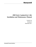
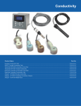
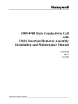
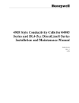
04973 Series Conductivity Cells
Installation and Maintenance Manual
70-82-25-17
10/07
Honeywell Field Solutions
Copyright, Notices, and Trademarks
Printed in U.S.A. – © Copyright 2007 by Honeywell Inc.
Revision– 10/07
Warranty/Remedy
Honeywell warrants goods of its manufacture as being free of defective materials and faulty
workmanship. Contact your local sales office for warranty information. If warranted goods are returned to
Honeywell during the period of coverage, Honeywell will repair or replace without charge those items it
finds defective. The foregoing is Buyer's sole remedy and is in lieu of all other warranties, expressed or
implied, including those of merchantability and fitness for a particular purpose. Specifications may
change without notice. The information we supply is believed to be accurate and reliable as of this
printing. However, we assume no responsibility for its use.
While we provide application assistance personally, through our literature and the Honeywell web site, it
is up to the customer to determine the suitability of the product in the application.
Honeywell Field Solutions
512 Virginia Drive
Fort Washington, PA 19034
Brands or product names are trademarks of their respective owners
ii
Installation and Maintenance Manual
10/07
About This Document
Abstract
The purpose of this manual is to support the installation and maintenance of the 4973 Series Conductivity
Cells.
Revision Notes
The following list provides notes concerning all revisions of this document.
Rev. ID
Date
Notes
0
10/96
This document is the initial release of the Honeywell version of the 4973
Series Conductivity Cell Installation and Maintenance Manual. This
publication was originally released under the L&N system as 277067 Rev.
N1.
1
6/99
Edits were made to add information for the 9782C and to correct some
erroneous information.
2
6/03
Edits were made to add information for the DL43XX Cells for DirectLine
Modules
3
6/04
Edit text and update the Installation drawings to remove 7082 information.
4
10/05
Edit text and add electrical connection drawings for UDA2182 analyzer
5
10/07
Edit text, add CRN approval, add quick disconnect info.
References
Honeywell Documents
The following list identifies all Honeywell documents that may be sources of reference for the material
discussed in this publication.
Document Title
10/07
ID #
APT2000CC Transmitter User Manual
70-82-25-95
APT4000CC Analyzer User Manual
70-82-25-104
UDA2182 Analyzer User Manual
70-82-25-119
Installation and Maintenance Manual
iii
Contacts
World Wide Web
http://hpsweb.honeywell.com
Telephone
Contact us by telephone at the numbers listed below.
Organization
Phone Number
United States and Canada
Honeywell
1-800-423-9883
iv
Installation and Maintenance Manual
Tech. Support
10/07
Contents
1.
INTRODUCTION ................................................................................................... 1
1.1
Overview ........................................................................................................................................ 1
1.2
Description ..................................................................................................................................... 1
2.
SPECIFICATIONS................................................................................................. 4
2.1
Specifications for 04973 Series ...................................................................................................... 4
2.2
Specifications for 055919 Flow Chamber ...................................................................................... 4
3.
INSTALLATION .................................................................................................... 5
3.1
General Requirements .................................................................................................................... 5
3.2
The Differences between the Quick Disconnect and Integral Cable Option.................................. 5
3.3
In-Line Type Mounting .................................................................................................................. 6
3.4
Flow-Type Mounting ..................................................................................................................... 6
3.5
Torque Recommendations.............................................................................................................. 7
3.6
Dimension Drawings ...................................................................................................................... 7
4.
ELECTRICAL CONNECTIONS........................................................................... 10
4.1
Overview ...................................................................................................................................... 10
4.2
Instrument Wiring for 4973 Cells with Integral Cable................................................................. 10
4.2.1 Model 4973 Series with Integral Cable to UDA2182 Analyzer........................................ 10
4.2.2 Model 4973 Series with Integral Cable to APT Series Analyzer/Transmitter................... 12
4.3
Instrument Wiring for 4973 Cells with Quick Disconnect Cable................................................. 13
4.3.1 Wiring Model 4973 with Quick Disconnect Cable to UDA2182...................................... 13
4.3.2 Wiring Model 4973 with Quick Disconnect Cable to Junction Box ................................. 13
4.3.3 Wiring Model 4973 with Quick Disconnect Cable to APT............................................... 14
5.
MAINTENANCE .................................................................................................. 15
5.1
Overview ...................................................................................................................................... 15
5.2
To Clean the Cell.......................................................................................................................... 15
5.3
Check Conductivity System ......................................................................................................... 15
5.4
Troubleshooting............................................................................................................................ 15
5.5
Air Entrapped in Cell Flow Channel ............................................................................................ 16
6.
10/07
ACCESSORIES AND SPARE PARTS ............................................................... 17
Installation and Maintenance Manual
v
Figures
Figure 1-1 4973 Type Conductivity Cells, for Flow and Insertion-type Applications. _______________ 2
Figure 1-2 Recommended Locations for Mounting a Conductivity Cell __________________________ 3
Figure 1-3 Two Piping Arrangements for the Cell ___________________________________________ 3
Figure 3-1 Dimension Drawing for 055919 Flow Chamber ___________________________________ 7
Figure 3-2 Dimension Drawing for 31079198 Flow Chamber__________________________________ 8
Figure 3-3 Outline and Dimensions for Conductivity Cell with Universal Head____________________ 8
Figure 3-4 Outline and Dimensions for Conductivity Cell with Integral Cable _____________________ 9
Figure 4-1 Installation Diagram, 4973 Cells, with junction box head connected to UDA2182 Analyzer 10
Figure 4-2 Installation Diagram, 4973 Cells, with Integral Cable Leads Directly Connected to UDA2182
Analyzer or Connected to Junction Box ______________________________________________ 11
Figure 4-3 Model 4973 Series to APT Series Analyzer/Transmitter ____________________________ 12
Figure 4-4 Wiring Diagram for 4973 Cells with Quick Disconnect Cable Connected to UDA2182
Analyzer_______________________________________________________________________ 13
Figure 4-5 Installation diagram for 4973 cells with Quick Disconnect Cable connected to junction box 13
Figure 4-6 Wiring Diagram for 4973 Cells with Quick Disconnect Cable Connected to APT4000 ____ 14
Figure 4-7 Wiring Diagram for 4973 Cells with Quick Disconnect Cable Connected to APT2000 ____ 14
vi
Installation and Maintenance Manual
10/07
Introduction
1. Introduction
1.1 Overview
The 4973 Type cells, Figure 1-1, have a rugged configuration for reliable, continuous measurements of
electrolytic conductivity in industrial water processes at temperatures up to 140°C at 250 psig. They are
applicable to such measurements as the effluent of distillation equipment; anion, cationic and mixed bed
ion exchangers; monitoring and controlling of washing electronic components; plating rinse tank control;
boiler water condensate; boiler hot well measurements and cooling tower blowdown, and many others.
Made of polyethersulfone (PES) construction for high-corrosion resistance, the cells are supplied with 0.01
and 0.1 cell constants having titanium electrodes, and 1.0 and 10.0 cell constants with high-density,
graphite electrodes.
The 4973 Cells used with UDA2182 Series or APT2000/4000 Series are equipped with the choice of:
•
integral standard 20 or 50 foot lead
•
quick disconnect cable option
•
junction box type (universal) head with terminal connections for longer lead lengths.
For in-line applications, the 3/4” NPT male thread permits permanent installation in a pipe or tank; the cell
may also be used as a laboratory dip-type cell for batch sampling.
For flow applications, the cell can be installed directly into a process stream as shown in Figure 1-2 by
using a Flow Chamber or a 3/4” pipe tee as shown in Figure 1-3. These arrangements are designed to keep
both the temperature compensator and cell in the main stream flow so that the cell will respond more
quickly and accurately to process changes of both solution concentration and temperature.
A 316SS (P/N 31079198) and a PES (P/N 055919) Flow Chamber is available from Honeywell.
1.2 Description
All conductivity cells of the 4973 Type are suitable for use in both flow and insertion - type installations.
They are one-piece molded units that cannot come apart and therefore have no replacement parts. Each has
a 3/4” NPT thread.
The physical appearance of the cells is shown in Figure 1-1. The 0.01, 0.1, 1 and 10 cell constants are
similar in construction with differences as noted below.
0.01 and 0.1 Cell Constants
The 0.01 cell differs from the others only by its outer electrode length of 2-3/4”. The temperature
compensation sensor is located inside the inner electrode. The holes in the outer electrode provide passage
for the solution being measured. The 0.1 cell is similar to the 0.01 type except that its outer electrode
length is 2”. The temperature compensation sensor is located inside the inner electrode.
1 and 10 Cell Constants
The 1 and 10 cell constant types are similar but differ in the width of flow channel (that serves to conduct
the solution being measured past the electrodes of the cell) as well as size and spacing of the electrodes.
The electrodes are graphite, 1/4” D for the 1 cell constant and 1/8” D for the 10 cell constant. The
temperature compensating sensor is integral with the cell body.
10/07
Installation and Maintenance Manual
1
Introduction
Potted
Potted
Connector
Connector
Housing
Housing *
1 1/8" Hex
Across Flats
3/4 NPT
Insertion
Depth
(See
Specifications)
Flow
Channel
Molding
Flow
Holes
Graphite
Electrodes
* This is the integral
cable option. Quick
disconnect option
also available.
Titanium
Electrodes
Teflon
Sheath
FLOW
Cell Constant
FLOW
0. 1
0.0 1
4973 Series
Cells Only
1.0
Universal Head
10
4973 Series
Cells Only
Conductivity
Cell
¾” Conduit
Figure 1-1 4973 Type Conductivity Cells, for Flow and Insertion-type Applications.
ATTENTION
Do not remove the Teflon sheath on 1.0 and 10 constant cells.
2
Installation and Maintenance Manual
10/07
Introduction
Process
Preferred
Cell Locations
Cool er
Pump
a/n 23340
Figure 1-2 Recommended Locations for Mounting a Conductivity Cell
*Maximum allowable operating temperature
for piping arrangements depends on the
type of pipe tee chosen.
Flow
(a) Cell Mounted in 3/4" NPT Pipe Tee* (Customer Supplied)
Flow
(b) Cell Mounted in PES Flow Chamber
a/n 23341
Figure 1-3 Two Piping Arrangements for the Cell
10/07
Installation and Maintenance Manual
3
Specifications
2. Specifications
2.1 Specifications for 04973 Series
Parameter
Description
Cell Constant
04973 Series: 0.01, 0.1, 1.0 and 10 as specified
Electrode Material
0.01 and 0.1 constant, titanium
1.0 and 10 constant, high density graphite with
Teflon sheath
Maximum Pressure Limit
1724 kPa (250 psig) at rated temperature
Maximum Continuous Temperature Limit
140°C (284°F) at rated pressure
For PVC wire:
105°C (221°F)
Materials of Construction
Cell Body: PES (polyethersulfone)
Electrodes: see ‘Electrode Material’
Cable Options
Leadwire: PVC insulated 18 gage cable
20 and 50 feet lengths available
Quick Disconnect Option
Universal Head (Aluminum)
Manufactured to comply with ASME boiler and
pressure vessel code Section III, Div.1, UG-101
Approvals
CRN #0F11607.5C
Insertion
3/4” NPT male, Schedule 40 and 80 pipes
Insertion Depth
3-1/2” (89 mm) for 1, 10 and 0.01 cell constants
from solution end of 3/4" MNPT
2-1/2” (64mm) for 0.1 cell constant
2.2 Specifications for 055919 Flow Chamber
Parameter
Description
Maximum Flow
2 gpm @ 40psig and atmospheric discharge
Maximum Pressure
200 psig @ 25°C
Maximum Temperature
140°C (284°F) at atmospheric pressure
Dimensions
See Figure 3-1
Materials of Construction
Polyethersulfone (PES)
4
Installation and Maintenance Manual
10/07
Installation
3. Installation
3.1 General Requirements
Observe the following before installing a conductivity cell. Specific requirements for particular types of
installation are given in Sections 3.3 and 3.4.
•
Do not remove the Teflon sheath on 1or 10 constant cells, as this will change the cell constant value.
•
Do not use the cell in solutions which can affect the fittings or the cell materials. If in doubt, contact
Honeywell.
•
Avoid all chlorinated hydrocarbons.
Titanium and PES (0.01 and 0.1 cell constants) and Graphite, Teflon and PES (1.0 and 10 cell
constants) are the only cell materials in contact with measured solutions. These materials are inert to
corrosive chemicals such as mineral acids, oxidizing agents and caustic solutions.
•
Avoid trapped air; see that air is not trapped in the cell flow channels.
•
Do not use the cell in solutions having temperatures or pressures greater than the maximum limits
stated in the Specifications.
•
Avoid locations where the operator must take an awkward position to install or remove the cell.
•
When tightening, do not exceed the torque limits provided in Section 3.5. Over-tightening can break
the cell or severely stress it causing cracks to develop, leading to eventual malfunction.
3.2 The Differences between the Quick Disconnect and Integral Cable
Option
The cable options of quick disconnect and integral cable do not affect the performance of the cell. These
options only relate to how the cell is connected to the instrument.
ATTENTION
•
The electrical connections are different for these options. Please refer to Section 4 for instructions.
•
The wire colors for the integral cable and quick disconnect option are not the same.
•
Integral cable means the cable is potted into the cell. The cable and cell are one entity and cannot be
separated.
•
The quick disconnect option means the cell is connected to the cell by a receptacle on the top of the
cell. The cell and the cable are separate entities. When the time comes to replace the cell, the cable
does not have to be replaced. The cable can simply be mated with another cell that has the quick
disconnect option. This option can not be used in immersion applications.
ATTENTION
The quick disconnect cable can be purchased from Honeywell.
10/07
Installation and Maintenance Manual
5
Installation
3.3 In-Line Type Mounting
In addition to the General Requirements outlined above, note the following with regard to insertion-type
mounting:
•
Make certain the liquid head is above the cell location during measurement. A vertical insertion (from
above) or a horizontal insertion can be used.
•
Allow at least one-half inch clearance beyond the end of the cell and 1/8 to 3/16 inch radius clearance
to permit circulation of the solution.
•
It is usually best to have the solution flow up into the end of the cell since it is less likely to result in
clogging by solids settling in the cell channels.
•
To be sure that a representative sample is being measured at all times, the solution must continuously
move through the cell channels. In a rapidly moving solution, the assembly may be mounted so that
the existing circulation forces the solution through the channels. When measurements are made in
quiescent solutions, artificial means must be provided to force the solution through the cell. In some
cases, this may be accomplished by moving the cell up and down.
Installation
Tighten the cell into a 3/4” NPT threaded opening (do not exceed a tightening torque greater than that
indicated in Section 3.5) using a Teflon thread compound (preferably Teflon tape).
3.4 Flow-Type Mounting
In addition to the General Requirements outlined in Section 3.1, note the following with regard to flowtype mounting:
•
When mounting the cell in a pipe tee or flow chamber such as shown in Figure 1-3, have the solution
enter the tee from below and exit to the side or from side and exit top. Be sure the electrodes are
always as far as possible below the horizontal pipe run so that they are always covered to insure
flooding of the cell under all conditions; otherwise, the conductivity reading may indicate a value that
is lower than expected.
•
In general, the cell should be mounted so that the sample will flow through the channel toward the
mounting end of the cell, exiting through the other channel hole or through the outer electrode holes.
See Figure 1-1.
•
Locate the cell on the pressure side, not the vacuum side, of pumps. See Figure 1-2.
•
Avoid a horizontal cell mounting having the flow channel, see Figure 1-1, opposite to the flow exit of
the pipe line, especially for the 1 and 10 constant cells. If necessary, refer to Section 5.5.
•
The 3/4” tee arrangement, Figure 1-3, assures that the cell is immersed well into the flow stream to
obtain a representative sample. The tee is not supplied.
Installation
6
1.
Tighten the cell into a 3/4” pipe tee (do not exceed a tightening torque greater than that indicated in
Section 3.5).
2.
If the flow-cell housing is used, assemble the cell and housing and install it in the process flow line or
in a bypass line as indicated in Figure 1-2.
3.
To avoid cracking the 055919 flow chamber, use Teflon tape on cell threads and tighten cell only
enough to prevent leakage.
Installation and Maintenance Manual
10/07
Installation
3.5 Torque Recommendations
For inserting a cell in metal fittings or bushings - 40 ft-lb maximum. For inserting a cell in plastic fittings
or bushings - 10 ft-lb maximum. Always use pipe sealant (preferably Teflon tape).
3.6 Dimension Drawings
1 1/ 8"
(38mm)
Hexagon
Flow Out
1 1/2"
(38mm)
3/4" NPT (Female)
1 1/2"
(38mm)
Octagon
3/4" NPT
(Male)
IN
CELL
1 1/2"
(38mm)
Flow Chamber
Flow In
8 3/4"
(222mm)
14 1/2" max
(368mm)
3/4" Fitting
Allow 4 1/8" (105mm) for re moval of cell
Notes:
1. Mount cell and flow chamber horizontally as shown above with flow exit up to eliminate
possible air gap around cell body.
2. If cell and flow chamber must be mounted vertically, attach a short length of tubing to flow
exit as shown below and form a trap to ensure filling of flow chamber, especially at low flow.
CELL
2" min.
(51mm)
IN
a/n23342
Figure 3-1 Dimension Drawing for 055919 Flow Chamber
10/07
Installation and Maintenance Manual
7
Installation
4.25
107.9
8-32 UNC – 2B 250 DEEP
1.0
25.4
.875
22.22
.50
12.7
1.5
38.1
3.75
95.25
4.0
101.6
1/8 NPT
4.5
114.3
3/4 NPT
Figure 3-2 Dimension Drawing for 31079198 Flow Chamber
0.593" Dia.
(15mm)
"X"
See Table
Dim "X"
Table I Inch mm
0.01
3.3
84
0.1
66
2.6
1.0
89
3.5
10
3.5
89
5.875"
(149.2mm)
3/4”
(76mm)
3/4 NPT
3/4"
1.13" Hex
(29mm)
¾” female NPT for user's
flexible electrical conduit
connection.. For insertion or
connection
removal of cell, disconnect
conduit connections.
Four Point Terminal
Board for lead wire
connections. Each #6-32
screw terminal will
wi
accomodate one
#12 or smaller AWG wire
NOTE: For existing users with conduit, a ¾” x ½” adapter bushing will be required to use existing
conduit.
Figure 3-3 Outline and Dimensions for Conductivity Cell with Universal Head
8
Installation and Maintenance Manual
10/07
Installation
“X”
± 0.031
± 0.787
2.771" ±.035
See Table
"Z"
(154mm ±.889)
"Y"
3/4" NPT
1 .1" Dia.
(27.9mm)
1.13" Hex
(29mm)
Suffix A
0.01
00.1
0.1
1.0
10
Dim "X"
mm
Inch
3.3 84
66
2.6
89
3.5
89
3.5
Dim "Y"
Inch mm
.703 17.85
.703 17.85
.593 1 5.06
.593 1 5.06
Cable iscable
approx.
0.250"
Internet
option
is (6.4mm)
O.D. with
4 (4973
SeriesO.D.
Cells)
approx.
0.250”
(6,4mm)
or 64 (DL4000
DirectLine
with
4973 Series
Cells Cells)
conductors
Dim "Z"
mm
Inch
.542 13.76
.542 13.76
.625 15.87
.564 14.32
Figure 3-4 Outline and Dimensions for Conductivity Cell with Integral Cable
10/07
Installation and Maintenance Manual
9
Electrical Connections
4. Electrical Connections
4.1 Overview
The terminal board connections for the various Honeywell measuring instruments are given in the
appropriate Figures in this section.
To avoid the possibility of AC pickup in the cell leads, separate them from all AC line-voltage wiring or
run them in a separate grounded conduit.
ATTENTION
Do not use shielded cable except where shown in the following figures.
4.2 Instrument Wiring for 4973 Cells with Integral Cable
4.2.1 Model 4973 Series with Integral Cable to UDA2182 Analyzer
NOTES
1. FOR PURE WATER SAMPLES IN NON-CONDUCTIVE (PLASTIC, GLASS, ETC.) PIPING, GROUND
THE BLACK CELL ELECTRODE LEAD NEAR THE CELL. ALTERNATIVELY, CONNECT TO THE UDA
GROUND SCREW AS SHOWN DOTTED. DO NOT GROUND 10, 25, OR 50 CONSTANT CELLS.
2. FOR CELL LEADS BLACK AND WHITE, USE 16 TO 22 AWG CABLE, SHIELDED TWISTED PAIR,
WITH 30 pF MAX. CAPACITANCE BETWEEN CONDUCTORS. CONNECT SHIELD TOTERMINAL
“10”. FOR MODEL 4973 INSTALLATIONS WITH HONEYWELL 31079198 SS FLOW CHAMBER, USE
22 AWG MINIMUM COAXIAL CABLE TYPE RG59U (BELDEN 9259 OR EQUIV.). CONNECT COAX
SHIELD TO TERMINALS “A” AND “10”. CONNECT COAX CONDUCTOR TO TERMINALS “C” AND “7”.
3. FOR COMPENSATOR LEADS B AND D, USE 16 TO 22 AWG, TWO CONDUCTOR CABLE.
4. CELL TO ANALYZER CABLES ARE CONSIDERED LOW LEVEL. RUN SEPARATE FROM HIGH
LEVEL WIRING.
DRAWING 50012874
Figure 4-1 Installation Diagram, 4973 Cells, with junction box head connected to UDA2182
Analyzer
10
Installation and Maintenance Manual
10/07
Electrical Connections
50
YELLOW
COAX
20 OR 50 FT. CABLE LENGTH.
Direct Cell to Analyzer Installation
50
Cell to Analyzer through Junction Box
NOTES
5. FOR PURE WATER SAMPLES IN NON-CONDUCTIVE (PLASTIC, GLASS, ETC.) PIPING, GROUND
THE BLACK CELL ELECTRODE LEAD NEAR THE CELL. ALTERNATIVELY, CONNECT TO THE UDA
GROUND SCREW AS SHOWN DOTTED. DO NOT GROUND 10, 25, OR 50 CONSTANT CELLS.
6. FOR CELL LEADS BLACK AND WHITE, USE 16 TO 22 AWG CABLE, SHIELDED TWISTED PAIR,
WITH 30 pF MAX. CAPACITANCE BETWEEN CONDUCTORS. CONNECT SHIELD TOTERMINAL
“10”. FOR MODEL 4973 INSTALLATIONS WITH HONEYWELL 31079198 SS FLOW CHAMBER, USE
22 AWG MINIMUM COAXIAL CABLE TYPE RG59U (BELDEN 9259 OR EQUIV.). CONNECT COAX
SHIELD FROM “BLACK” TO TERMINAL “10”. CONNECT COAX CONDUCTOR FROM “WHITE” TO
TERMINAL “7”.
7. FOR COMPENSATOR LEADS RED AND GREEN, USE 16 TO 22 AWG, TWO CONDUCTOR CABLE.
8. CELL TO ANALYZER CABLES ARE CONSIDERED LOW LEVEL. RUN SEPARATE FROM HIGH
LEVEL WIRING.
DRAWING 50012875
Figure 4-2 Installation Diagram, 4973 Cells, with Integral Cable Leads Directly Connected
to UDA2182 Analyzer or Connected to Junction Box
10/07
Installation and Maintenance Manual
11
Electrical Connections
4.2.2 Model 4973 Series with Integral Cable to APT Series Analyzer/Transmitter
04973 series cells with integral cable leads connected to an APT4000
04973 series cells with integral cable leads connected to an APT2000
Figure 4-3 Model 4973 Series to APT Series Analyzer/Transmitter
12
Installation and Maintenance Manual
10/07
Electrical Connections
4.3 Instrument Wiring for 4973 Cells with Quick Disconnect Cable
4.3.1 Wiring Model 4973 with Quick Disconnect Cable to UDA2182
Wire
Color
Signal
Name
Yellow
10
Cell Low
9
8
7
Coax
Cell High
6
RTH 3rd Wire
Green
5
RTH Low
Red
4
RTH High
Brown
3
Blue
2
Jumper
Wire to chassis
ground screw
1
Earth Ground
Figure 4-4 Wiring Diagram for 4973 Cells with Quick Disconnect Cable Connected to
UDA2182 Analyzer
4.3.2 Wiring Model 4973 with Quick Disconnect Cable to Junction Box
50
YELLOW
COAX
20 OR 50 FT. CABLE LENGTH.
DRAWING 50012875
Figure 4-5 Installation diagram for 4973 cells with Quick Disconnect Cable connected to
junction box
10/07
Installation and Maintenance Manual
13
Electrical Connections
YELLOW
NOTE: IGNORE BLUE AND BROWN WIRES.
COAX
4.3.3 Wiring Model 4973 with Quick Disconnect Cable to APT
COAX
NOTE: IGNORE BLUE AND BLACK WIRES.
YELLOW
Figure 4-6 Wiring Diagram for 4973 Cells with Quick Disconnect Cable Connected to
APT4000
Figure 4-7 Wiring Diagram for 4973 Cells with Quick Disconnect Cable Connected to
APT2000
14
Installation and Maintenance Manual
10/07
Maintenance
5. Maintenance
5.1 Overview
The only maintenance that may be required is occasional cleaning. When cleaning, avoid scratching
electrode surfaces. Do not use a brush or pipe cleaner.
5.2 To Clean the Cell
The cell will require cleaning if sludge, slime, etc., accumulate in the flow channels. Since the materials of
construction are chemically inert, chemical agents may be used and are recommended for cleaning the
cells. The particular cleaning agent used must be selected according to the type of contamination to which
the cell is exposed.
The cell housing is made of a polyethersulfone, PES, and must not be cleaned with acetone, chloroform,
toluene, benzene, or other chlorinated hydrocarbons.
In general, a “quick” rinse in a 10% inorganic acid is effective and often adequate. Another method is to
use a strong stream of water to dislodge particles; then reverse flush. After cleaning, rinse the cell
thoroughly in tap water and then distilled water, if available. Take care not to scratch electrode surfaces.
5.3 Check Conductivity System
To check the conductivity system comprising the conductivity cell, leadwires, and measuring instrument,
make a measurement in a reference solution of known conductivity. Alternatively, use a second cell
having the same constant and temperature compensation and compare the two readings. Be sure the cells
are not touching the bottom or sides of the container for this test.
If Table II of the conductivity cell model number is 333, the normal resistance of the temperature sensor as
measured across the red (B) and green (D) leads is 8550 ohms at 25 C.
To check the electrode insulation, connect an ohmmeter across the black (A) and white (C) leads. With a
dry and clean cell, the resistance should be greater than 50 megaohms.
5.4 Troubleshooting
A series of below normal conductivity readings could indicate that the cell is not filled with solution
resulting in a lack of response.
If the plastic surface of the cell has a grayish dull appearance instead of its normal glassy appearance, the
cell has been exposed to temperature above its specified maximum. Check the solution temperature and
replace the conductivity cell.
10/07
Installation and Maintenance Manual
15
Maintenance
5.5 Air Entrapped in Cell Flow Channel
If measurement errors appear for horizontal mountings of a 1 or 10 constant cell, it may be that air is
entrapped in the cell flow channel. Take one of the following actions to eliminate this problem:
16
•
Increase flow to at least 1 gpm.
•
Rotate the cell mounting so that its flow channel faces the same direction as the pipeline flow exit.
•
Install the cell and/or flow chamber vertically.
Installation and Maintenance Manual
10/07
Accessories and Spare Parts
6. Accessories and Spare Parts
Description
Part Number
Flow Cell Housing (PES)
055919
Flow Cell Housing (316 SS)
31079198
Junction Box
31316260
Teflon Shield
White for 1 const. cell
31021599
Clear for 10 const. cell (see note below)
31018760
Extension Cables for Sensors with Quick Disconnect Option
2 m (6.56 ft.)
50024092-001
3 m (9.84 ft.)
50024092-002
6 m (19.69 ft.)
50024092-003
15 m (49.21 ft.)
50024092-004
Extension Cable must be purchased from Honeywell
Cell Extension Leadwire
For ATC value of 333:
Standard Range 9782 or 7082, also APT 2000
To 500 ft.:
3-conductor, 18 gage cable (Belden 9493) and
Coax cable (Belden 9259)
834059
835024
To 1000 ft.:
Coax cable (Belden 9259)
835024
Wide Range 9782 and 7082
To 500 ft.:
4-conductor, 18 gage cable only
To 1000 ft.:
4-conductor (3 used), 16 gage only
31834052
834055
For all cells with an ATC other than 333:
3-conductor, 18 gage cable (Belden 9493) only
834059
Note: For 10 constant cell, heat shrink the clear shield onto the cell using a 300°F max. temp.
(Cal Factor may change)
10/07
Installation and Maintenance Manual
17
Accessories and Spare Parts
18
Installation and Maintenance Manual
10/07
Honeywell Field Solutions
512 Virginia Drive
Fort Washington, PA 19034
70-82-25-17 10 07 Printed in USA
http://hpsweb.honeywell.com