1
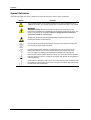
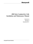
4909/4908 Style Conductivity Cell
with
316SS Insertion/Removal Assembly
Installation and Maintenance Manual
70-82-25-68
Rev. 4
June 2009
Honeywell Process Solutions
Contents
Copyright, Notices, and Trademarks
Printed in U.S.A. – © Copyright 2007 by Honeywell Inc.
Revision 4 – June 2009
While this information is presented in good faith and believed to be
accurate, Honeywell disclaims the implied warranties of
merchantability and fitness for a particular purpose and makes no
express warranties except as may be stated in its written agreement
with and for its customer.
In no event is Honeywell liable to anyone for any indirect, special or
consequential damages. The information and specifications in this
document are subject to change without notice.
Honeywell Process Solutions
512 Virginia Drive
Fort Washington, PA 19034
ii
4909/4908 316SS Conductivity Cell Insertion/Removal Assembly
June 09
Contents
About This Document
Abstract
This document is intended to support the installation, operation and maintenance of the 4909/4908 Style
Conductivity Cell with 316SS Insertion/Removel Assembly.
Revision Notes
The following list provides notes concerning all revisions of this document.
Rev. ID
Date
Notes
0
2/87
This document is the initial Honeywell release of the L&N manual p/n
177770. There has been no significant changes made to this manual. The
format has been changed to reflect the Honeywell layout and some part
numbers have been changed to reflect Honeywell database structure.
1
6/99
Edits were made to make descriptions consistent and a new MSG was
added.
2
7/06
Edits to Maintenance, Spare Parts, and Wiring
3
10/07
Edits to specifications, spart parts, wiring
4
June 09
Consolitation
References
Honeywell Documents
The following list identifies all Honeywell documents that may be sources of reference for the material discussed in
this publication.
Document Title
ID #
UDA2182 Universal Dual Analyzer User Manual
70-82-25-119
APT2000CC Transmitter User Manual
70-82-25-95
APT4000CC Analyzer User Mnaual
70-82-25-104
Contacts
World Wide Web
http://hpsweb.honeywell.com
Telephone
Contact us by telephone at the numbers listed below.
Organization
United States and Canada
June 09
Honeywell
Phone Number
1-800-423-9883
4909/4908 316SS Conductivity Cell Insertion/Removal Assembly
iii
Contents
Symbol Definitions
The following table lists those symbols used in this document to denote certain conditions.
Symbol
Definition
This CAUTION symbol on the equipment refers the user to the Product Manual for
additional information. This symbol appears next to required information in the manual.
WARNING
PERSONAL INJURY: Risk of electrical shock. This symbol warns the user of a
potential shock hazard where HAZARDOUS LIVE voltages greater than 30 Vrms, 42.4
Vpeak, or 60 Vdc may be accessible. Failure to comply with these instructions
could result in death or serious injury.
ATTENTION, Electrostatic Discharge (ESD) hazards. Observe precautions for
handling electrostatic sensitive devices
Protective Earth (PE) terminal. Provided for connection of the protective earth (green
or green/yellow) supply system conductor.
Functional earth terminal. Used for non-safety purposes such as noise immunity
improvement. NOTE: This connection shall be bonded to protective earth at the
source of supply in accordance with national local electrical code requirements.
Earth Ground. Functional earth connection. NOTE: This connection shall be bonded to
Protective earth at the source of supply in accordance with national and local electrical
code requirements.
Chassis Ground. Identifies a connection to the chassis or frame of the equipment shall
be bonded to Protective Earth at the source of supply in accordance with national and
local electrical code requirements.
iv
4909/4908 316SS Conductivity Cell Insertion/Removal Assembly
June 09
Contents
Contents
1.
INTRODUCTION ................................................................................................... 1
1.1
2.
Description ..................................................................................................................................... 1
1.1.1 4908 Style Insertion Cell ..................................................................................................... 2
1.1.2 31741450 Removal Device ................................................................................................. 2
SPECIFICATIONS AND MODEL SELECTION GUIDE ........................................ 3
2.1
3.
Specifications ................................................................................................................................. 3
INSTALLATION .................................................................................................... 4
3.1
Overview ........................................................................................................................................ 4
3.2
Location and Position ..................................................................................................................... 4
3.3
Preparing Insertion Tube Assembly ............................................................................................... 5
3.4
Installation Procedure..................................................................................................................... 6
4.
ELECTRICAL CONNECTIONS .......................................................................... 11
4.1
Overview ...................................................................................................................................... 11
4.2
Instrument Wiring ........................................................................................................................ 11
4.2.1 Model 4909/4908 Series to UDA2182 Analyzer............................................................... 12
5.
MAINTENANCE .................................................................................................. 15
5.1
Introduction .................................................................................................................................. 15
5.2
Cleaning the Cell .......................................................................................................................... 15
5.3
Platinizing the Cell Electrodes ..................................................................................................... 15
5.4
Reference Solutions of Known Conductivity............................................................................... 16
5.5
Leakage from Removal Device .................................................................................................... 16
5.6
Replacement Parts and Accessories ............................................................................................. 18
June 09
4909/4908 316SS Conductivity Cell Insertion/Removal Assembly
v
Contents
Tables
Table 1-1. Specific Conductance of Sample Solutions for Corresponding Measured Resistance Values... 2
Table 5-1 Voltage and Time Limits for Platinizing Cells........................................................................... 16
Table 5-2 Standard Reference Solutions..................................................................................................... 17
Table 5-3 Replacement Parts and Accessories ........................................................................................... 18
Figures
Figure 1-1. 4909 Conductivity Cell Assembly Installed in 31741450 Removal Device ............................. 1
Figure 3-1 Recommended Locations for Mounting a Conductivity Cell...................................................... 5
Figure 3-2 Mounting the Retainer on the Mounting Tube............................................................................ 6
Figure 3-3 Cell Assembly Dimensions and Parts Identification ................................................................... 7
Figure 3-4 Outline and Dimension Drawing for Insertion/Removal Mounting and Cell with Junction Box8
Figure 3-5 Outline and Dimension Drawing for Insertion/Removal Mounting and Cell with Cable........... 9
Figure 4-1 Installation Diagram, 4909/4908 Cells, with junction box head connected to UDA2182
Analyzer............................................................................................................................................... 12
Figure 4-2 Installation Diagram, 4909/4908 Cells, with cable leads directly connected to UDA2182
Analyzer or connected to junction box ................................................................................................ 13
Figure 4-3 4909/4908 Series to APT Series Analyzer/Transformer .......................................................... 14
Figure 5-1 Details of Stuffing Box ............................................................................................................. 17
vi
4909/4908 316SS Conductivity Cell Insertion/Removal Assembly
June 09
Introduction
1. Introduction
1.1 Description
The stainless steel 4909 style conductivity cell assembly is designed for use in a pipe line or closed vessel
where it is desirable to remove the cell for inspection and maintenance without shutting down the system
and releasing the pressure. The assembly comprises a 4908 Insertion Cell and a 3131741450 Cell Removal
Device which are shown assembled in Figure 1-1. It is to be used in applications for which maximum
pressure does not exceed 200 psi and can be reduced to 50 psi during insertion and removal of the cell.
Maximum operation temperature is determined by the temperature compensator range. Do not use in
solutions above 284°F (140°C).
The depth of insertion is 6-1/2 to 9 inches from the mounting nipple on the removal device.
The entire insertion-cell assembly is made from polyethersulfone (PES) with Ryton support fittings, which
is resistant to most corrosive inorganic chemicals over a wide range of temperatures. (A common
exception is chlorinated hydrocarbons and ketones.) Sample solutions come into contact with the PES and
the platinum, nickel or Monel electrode surface of the cell. ( Cell constant determines electrode material.)
The only other materials of the 4909 Assembly with which the sample solution may come into contact are
the stainless steel removal device, a stainless steel retainer ring and a Viton-A O-ring.
Stuffing Box
Valve
Insertion Cell
Valve Nipple
Insertion Cell
a/n 23562
Figure 1-1. 4909 Conductivity Cell Assembly Installed in 31741450 Removal Device
CAUTION
Specific parameters of your process may prohibit the use of nickel elements. For example, always use a
platinum-element cell if the cell will measure or be exposed to regeneration acids (except the 0.1 cell constant,
which is only supplied as Monel).
ATTENTION
Conductivity Cells are manufactured with an embedded EEProm that contains the cell constant and
cell factor information. When the EEProm leads (Brown and Blue) , junction box head terminals (E)
and (F) are connected to a UDA2182 Analyzer these parameters are automatically uploaded into
the analyzer.
June 09
4909/4908 316SS Conductivity Cell Insertion/Removal Assembly
1
Introduction
1.1.1 4908 Style Insertion Cell
General
The molded conductivity cell and its one-inch diameter mounting tube (with retaining ring) comprise a one
piece cell unit and are made of polyethersulfone and Ryton. The retaining ring and an O-ring which
secures it in a concentric groove in the cell mounting tube are supplied in place. This stainless steel ring
serves as a stop during the removal operation. The retainer O-ring is Viton-A. The insertion cell is
supplied with either 20 feet of PVC-sheathed cable, or an integral junction box head.
Conductivity Cell
The cells having constants of 10 and 50 cm-1 are intended for making measurements in highly conductive
solutions. They differ in construction from those having constants of 0.01, 0.1, or 1cm-1. On the 50
constant cells, the electrodes are short tubes located midway inside the two parallel tubular channels that
run lengthwise through the cell, and are open to the sample at both ends of the cell. The 0.01, 0.1, and 1.0
constant cells have a removable cell guard which is screwed onto the cell body to protect the electrode
surfaces. Electrodes are three discs on the 1.0 constant cell, parallel plates on the 0.1 constant cell, and a
pair of concentric wires wound on the cell body on the 0.01 constant cell. Cells must be used with the
guard in place or the cell constant may differ from that specified.
Table 1-1 lists the specific conductance possible with each of the cell constants. This table is provided for
general information only, and is not needed for measurements.
1.1.2 31741450 Removal Device
This device consists of a ball valve which is connected to the closed system by a 1-1/4 inch standard pipe
thread mounting nipple and to a stuffing box by a 6-5/8 inch long special nipple into which the cell
mounting tube is inserted. The stuffing box provides a seal around the cell mounting tube. The material
used is 316 stainless steel.
Table 1-1. Specific Conductance of Sample Solutions for Corresponding Measured Resistance
Values
Cell
Constant
100 Ohms
10000 Ohms
50000 Ohms
0.01
100 μmho/cm
1 μmho/cm
0.2 μmho/cm
0.1
1000 μmho/cm
10 μmho/cm
2 μmho/cm
10000 μmho/cm
100 μmho/cm
20 μmho/cm
10
100000 μmho/cm
1000 μmho/cm
200 μmho/cm
50
500000 μmho/cm
5000 μmho/cm
1000 μmho/cm
1.0
Note: Table 1-1 has been provided for reference only.
2
4909/4908 316SS Conductivity Cell Insertion/Removal Assembly
June 09
Specifications and Model Selection Guide
2. Specifications and Model Selection Guide
2.1 Specifications
Cell Constants:
Model 4909/4908: 0.01, 0.1, 1.0, 10, and 50 cm-1
Electrode Material: Nickel, Platinum, or Monel as specified
Maximum Pressure Limit: 200 psi. @100°C -.
For CRN Approval: 80 psig @140° C
Maximum Temperature Limit: 140°C Mounting: 1-1/4” NPT male pipe.
Insertion Depth: Varies between 6-1/2” and 9” nominal, depending upon cell constant.
Wetted Parts: Immersed parts are: Polyethersulfone (PES) with Ryton support fittings, Viton A, 316 SS,
and Nickel, Platinum or Monel electrode. Mounting materials are 316 Stainless Steel.
Electrical Connections: Six leads with integral automatic temperature compensator.
Leadwire: PVC covered, 22-gage cable, 20’ long, as specified.
If more than 20’ required, use Universal Head Cast Aluminum Junction Box and appropriate length of
cable. See Section 4 for options. Universal Heads are cast aluminum 3/4” female NPT with 1/2” NPT
female adapter bushing, female conduit connection and terminals to accommodate cell and automatic
temperature compensator connections.
CRN Approvals: Manufactured to comply with ASME Boiler and Pressure Vessel Code , Section III, Div
1, UG-101. CRN # 0F11607.5C
Weight: 20 lb. (9.1 kg).
June 09
4909/4908 316SS Conductivity Cell Insertion/Removal Assembly
3
Installation
3. Installation
3.1 Overview
To insure that a representative sample is being measured at all times, the solution must move through the
cell channels or guard tube. If the measurement is made in a rapidly moving liquid, the existing circulation
of the solution can be utilized by mounting the assembly as described in the next section so that the flow of
the solution forces liquid through the cell. However, when measurements are to be made in quiescent
solutions, means must be provided for forcing the solution through the conductivity cell or care taken to
place the cell in a position to “see” the true value of the solution.
Do not use the cells in solutions which will attack the fittings used or the cell materials. The PES and
platinum, nickel or Monel of the electrode, the stainless-steel retainer, and the Viton A retainer O-ring are
the cell materials with which the solution will come into contact. The removal device is 316 stainless steel.
Do not use the cell in a solution having temperatures greater than 140°C. The maximum limit set by the
temperature compensator range must be observed.
For cells having a constant of 0.01, 0.1 or 1, make certain that the guard is in place and is not loose on the
cell body. The guard tube must be hand-tightened only. There is a 1/16 inch space between the guard tube
and the cell body.
Although the cell has excellent shock resistance characteristics, never subject it to mechanical abuse.
ATTENTION
Conductivity cells have an EEPROM device for automatic download of cell constant and cell calibration
factor. During installation proper ESD protection is required so the memory device is not damaged.
WARNING
For 6 conductor cells, EEPROM memory device is ESD sensitive- blue and brown leads; junction box head
terminals (E) and (F)
3.2 Location and Position
The cross-channel in the high constant cells or the guard tube holes in the low constant cells must be
covered by the solution during measurements.
Vertical insertion (from above) or horizontal insertion can be used. Make certain the tank or pipe line is full
under all process conditions. If a pipe line is not always full, use a vertical mounting as in Figure 3-1and
insert the cell far enough into the vertical pipe that the cross-channel is below the horizontal exit pipe
which may empty out. Make certain an air bubble in the pipe does not prevent the cell from filling properly.
(If the cell becomes dry after use, it may require cleaning in accordance with Section 5.2 before again being
placed in service.)
For best results, whether vertical or horizontal mounting is used, position the cell so that the sample will
flow through the channels or guard tube towards the mounting end of the cell, exiting through the crosschannel or guard-tube holes. In applications where vertical mounting is required, avoid a position with the
cell channels pointed up, as this will permit solution to flow down into the open end of the cell and may
result in clogging by solids settling in the cell channels.
4
4909/4908 316SS Conductivity Cell Insertion/Removal Assembly
June 09
Installation
Allow for a total insertion depth of about ten inches from the outside wall of the mounting surface as
indicated by the dimensions in Figure 3-4.
Allow at least one-half inch clearance beyond the end of the cell and 1/8 to 3/16 inch radius clearance
surrounding the cell to permit circulation of the solution.
If not part of the cell assembly, place the temperature compensator close enough to the cell to eliminate a
significant temperature difference in the liquid between the two points. If necessary, lag the pipe between
the two points to prevent rapid cooling. Avoid locations where excessive temperature changes may occur.
Allow at least 30 inches clearance behind the stuffing box to permit removal.
Locate the insertion assembly on the pressure side of pumps; not the vacuum side.
Avoid locations where the operator must take an awkward position to perform the cell insertion or removal
operation.
Figure 3-1 illustrates recommendations for locating and mounting both the cell assembly and the
temperature compensator. Refer to Figure 3-3, Figure 3-4, or Figure 3-5 for mounting dimensions.
Preferred
Cell Locations
Process
Cooler
1.5"
Pump
a/n 23563
Figure 3-1 Recommended Locations for Mounting a Conductivity Cell
3.3 Preparing Insertion Tube Assembly
June 09
1.
Take out the forward screw (valve end) of the stuffing box and unscrew the box from the valve nipple.
2.
Slide the insertion tube into the smaller opening in the stuffing box, while holding in the washer, gland
ring, and compression seal.
3.
Roll the O-ring over the end of the insertion tube and into the concentric groove. Use a small
screwdriver or pointed object to pry out a side of the O-ring and stretch it about one inch from the tube
to reduce its cross section. Insert the U-shaped retaining ring in the slot. Figure 3-2 illustrates this
operation. With the grooved side of the retainer against the O-ring, press the retainer in on one side
while pulling on the O-ring from the opposite side as shown. Rotate the retainer back and forth until
all of the stretched slack is taken back into the slot. Make certain the retainer is pushed all the way in.
4909/4908 316SS Conductivity Cell Insertion/Removal Assembly
5
Installation
a/n 23567
Figure 3-2 Mounting the Retainer on the Mounting Tube
3.4 Installation Procedure
ATTENTION
Before making the initial installation, remove the stuffing box, slide the mounting tube through the
unthreaded end of the box and slide the retaining ring in place on the tube in accordance with the
procedure outlined below.
Insertion
1.
Remove both knurled screws from the stuffing box and slide the insertion tube into the valve nipple.
2.
Screw the stuffing box onto the nipple and tighten the forward knurled screw all the way down. Hand
tighten the stuffing box so that the tube slides stiffly when pushed.
3.
Reduce process pressure to 50 psig or less. Open the valve.
4.
Push the insertion tube all the way in and tighten the back knurled screw on the stuffing box all the
way down. Note that the shoulder on the tube must be sealed in the stuffing box before the lock screw
is tightened.
5.
Hand tighten the stuffing box and return the process to normal operating pressure.
Removal
6
1.
Reduce process pressure to 50 psig or less.
2.
Remove the back knurled screw on the stuffing box. (If the tube moves back, apply slight force to let
it slide out slowly.)
3.
Allow the tube assembly to be forced out to its stop and close the valve. (If necessary, turn the stuffing
box very slightly.)
4.
Remove the other knurled screw and unscrew the stuffing box to remove it.
4909/4908 316SS Conductivity Cell Insertion/Removal Assembly
June 09
Installation
Retainer
O-Rin
O-Ring
Retaining Ring
2.9"
(73.7mm)
Stuffing Box
Valve Nipple
4.00"
(101.6mm)
Approx. 14.5"
(368.3mm)
Mounting
Tube
Allowa minimumof
30" (762mm) clearance
beyondthis point
for removal.
Figure 3-3 Cell Assembly Dimensions and Parts Identification
June 09
4909/4908 316SS Conductivity Cell Insertion/Removal Assembly
7
Installation
Figure 3-4 Outline and Dimension Drawing for Insertion/Removal Mounting and Cell with
Junction Box Head
8
4909/4908 316SS Conductivity Cell Insertion/Removal Assembly
June 09
Installation
Figure 3-5 Outline and Dimension Drawing for Insertion/Removal Mounting and Cell with Cable
June 09
4909/4908 316SS Conductivity Cell Insertion/Removal Assembly
9
Electrical Connections
4. Electrical Connections
4.1 Overview
The terminal-board connections for recorder or analyzer are given in the appropriate directions furnished
with the measuring instrument.
To avoid the possibility of ac pick-up in the cell leads, separate them from all ac line-voltage wiring or run
them in a separate grounded conduit.
WARNING
For 6 conductor cells, EEPROM memory device is ESD sensitive- blue and brown leads; junction box head
terminals (E) and (F)
June 09
4909/4908 316SS Conductivity Cell Insertion/Removal Assembly
11
Electrical Connections
4.2 Instrument Wiring
4.2.1 Model 4909/4908 Series to UDA2182 Analyzer
Drawing 50043652
Figure 4-1 Installation Diagram, 4909/4908 Cells, with junction box head connected to
UDA2182 Analyzer
12
4909/4908 316SS Conductivity Cell Insertion/Removal Assembly
June 09
Electrical Connections
Drawing 50043654
Figure 4-2 Installation Diagram, 4909/4908 Cells, with cable leads directly connected to UDA2182
Analyzer or connected to junction box
June 09
4909/4908 316SS Conductivity Cell Insertion/Removal Assembly
13
Electrical Connections
Brown and Blue
wires not used
04905
series
cells
with
20’ leads
04905
series
cells
with
cable
leadsconnected
connectedtotoananAPT4000
APT4000
Brown and Blue
wires not used
04905
series
cells
with
or 20’
leads
connected
APT2000
04905
series
cells
with
cable
leads
connected
totoananAPT2000
Figure 4-3 4909/4908 Series to APT Series Analyzer/Transformer
14
4909/4908 316SS Conductivity Cell Insertion/Removal Assembly
June 09
Maintenance
5. Maintenance
5.1 Introduction
If a series of below-normal readings occurs, this may indicate poor response because the cell is not filled
with process solution. Check the cell installation. Note that a grayish dull surface on the cell plastic
(normally glassy) can result from exposure to temperatures above 140°C.
The only maintenance which may be required is occasional cleaning in certain applications. The low
constant electrodes are not platinized. To remove or replace the cell, refer to Section 1.
NOTE: Never connect a test instrument across the Blue (E) and Brown (F) leads. Damage to the cell
memory device may occur.
5.2 Cleaning the Cell
CAUTION
The cell housing is PES (polyethersulfone). Do not clean with acetone, chloroform, toluene, benzene, or any
other chlorinated hydrocarbon.
The cell will require cleaning if sludge, slime, etc., accumulates in the flow channels. Since the materials
of construction are chemically inert, chemical agents may be used and are recommended for cleaning the
cells. The particular cleaning agent used must be selected according to the type of contamination to which
the cell is exposed. In general, soap and hot water cleaning solution is effective. Immerse the plastic body
of the cell in this solution. A 10 or 15 minute soaking period should be adequate. If necessary, a soft
bristle brush of about 1/4 inch diameter may be used to clean out the tubular channels of the 10 and 50
constant cells. Care must be taken not to scratch the electrode surfaces. Do not use a brush on the low
(0.01, 0.1 and 1) constant cells and be especially careful not to bend the electrode plates of the 0.1 constant
cell. Rinse the cell thoroughly in tap water and then in distilled water if available. To remove the platinum
black from electrodes (10 and 50 constants only), refer to Section 5.3 Replatinizing after each cleaning (10
and 50 constant cells only), may not be necessary unless brushing was used.
5.3 Platinizing the Cell Electrodes
Only the electrodes having constants 10 and 50 must be replatinized if the velvety-black deposit has been
rubbed off the electrodes in service or in cleaning or if platinized electrodes are recommended and this
black deposit is not present when the new cell is received. Always replatinize if a brush was used in
cleaning the electrodes. The indication of a need for replatinization of the electrodes is loss in sensitivity
(slow response of measuring instrument), erratic behavior of measuring instrument, or difficulty in
balancing. The electrodes of the high constant cells are not visible since they are located near the middle of
the flow channels. Therefore the need for platinization is only indicated by the effect on the measuring
instrument. Do not platinize cells intended for high purity water measurements.
Before platinizing, clean the cell with detergent and brush as described in Section 5.2.
Support the cell in a cylindrical vessel with the end of the cell raised from the bottom. It is not necessary to
remove the cell from the fittings for platinizing. However, the guard tube must be removed from the low
constant cells. Pour in a platinizing solution to a level above the cross-channel.
To platinized the 10 or 50 constant cells, immerse an auxiliary platinum electrode in the solution to a point
about midway between the cross-channel or tube hole and the open end of the cell. (This third electrode
should be chemically pure platinum. Its shape is unimportant. It may be one of the electrodes in another
June 09
4909/4908 316SS Conductivity Cell Insertion/Removal Assembly
15
Maintenance
conductivity cell or a platinum strip, sheet, rod, wire, etc.) Both electrodes of the cell are platinized
simultaneously by connecting the negative terminal of the battery (see Table 5-1) to both leadwires of the
cell. Connect the positive terminal of the battery to the auxiliary platinum electrode. Note the time lapse
and continue the platinizing operation for the time in seconds listed in Table 5-1. Then disconnect the
battery and remove the cell. Rinse the cell thoroughly in tap water and then rinse in distilled water. During
the platinizing operation, move the cell up and down gently to keep the solution stirred.
CAUTION
The preceding procedure produces a barely visible coating of platinum black on the electrode surfaces. Do not
attempt to darken electrodes by additional platinization since this will affect the cell performance adversely.
Pour the platinizing solution back into its container as it may be used a number of times.
If the cell is not to be installed immediately after platinizing, it should be kept submerged in distilled water
until put into use, as platinum black is not stable when dry.
Table 5-1 Voltage and Time Limits for Platinizing Cells
DC
10
50
Volts
6.0
100 sec.
300 sec.
12.0
----
240 sec.
5.4 Reference Solutions of Known Conductivity
To check the system comprising conductivity cell, leadwire, and measuring instrument, the user may desire
to make a measurement in a reference solution of known conductivity. Table 5-2 defines the standard
solutions and lists their conductivity. Control the temperature only within limits consistent with the desired
accuracy. The 25°C temperature value is suggested. For cell constants less than 10 use a good known
reference solution from a laboratory supply vendor.
5.5 Leakage from Removal Device
Do not use excessive force when tightening the stuffing box as this may distort the end of the valve nipple
on which the stuffing box is mounted. Leakage which cannot be stopped by normal tightening of the
stuffing box may be corrected if the plastic washer is renewed See Figure 5-1. If not, the leakage may have
been caused by slight distortion of the mating surfaces of the nipple and gland ring. If these surfaces are
cleaned, the sliding fit will be improved; distortion and its resulting leaks will be prevented.
To clean the mating surfaces between the gland ring and the nipple, first remove the stuffing box and take
out the gland ring. Clean the surfaces with a flat, fine sandstone, changing the direction of stroke about 15
degrees per stroke to keep the surfaces parallel.
16
4909/4908 316SS Conductivity Cell Insertion/Removal Assembly
June 09
Maintenance
Valve
Stuffing Box
Mounting
Nipple
Valve Nipple
Insertion Cell
Cell Guard Tube
Plastic Washer
Figure 5-1 Details of Stuffing Box
Table 5-2 Standard Reference Solutions
Approximate
Normality
1.0 N
June 09
Definition
71.1352 grams
KC1 per 1000
grams of water
O
Temp C
0
18
25
Specific
Conductance
(micromhos)
65,176
97,838
111,342
4909/4908 316SS Conductivity Cell Insertion/Removal Assembly
Nominal Constant
of Cell to be
Checked
10, 50
17
Maintenance
5.6 Replacement Parts and Accessories
Replacement parts and accessories are listed in Table 5-3.
Table 5-3 Replacement Parts and Accessories
Description
Part No.
Retainer Ring
31027158
Retainer O-Ring
31082053
Complete Removal Device 316 Stainless Steel without Cell Assembly
31741450
Short Mounting Nipple, 1-1/4” NPT 316 Stainless Steel
31020953
Ball Valve 316 Stainless Steel
31020868
Long Valve Nipple 316 Stainless Steel
31076635
316 Stainless Steel Stuffing Box (does not include following parts)
31500697
316 Stainless Steel Gland Ring (between packing and plastic washer)
31001215
Safety Chain Monel and Brass
31500464
Compression Seal (Viton)
31071494
Viton Washer (covers gland ring)
31301277
Cell Extension Leadwire (see Fig 4.1 & 4.2 for required cables)
18
18 AWG, Low capacitance shielded twisted pair
BELDEN 8760 or
equivalent
22 AWG, Coax RG59U
BELDEN 9259 or
equivalent
18 AWG, 4 conductor
BELDEN 8489 or
equivalent
4909/4908 316SS Conductivity Cell Insertion/Removal Assembly
June 09
Maintenance
June 09
4909/4908 316SS Conductivity Cell Insertion/Removal Assembly
19
Honeywell Process Solutions
512 Virginia Drive
Fort Washington, PA 19034
70-82-25-68 June 09 Printed in USA
www.honeywell.com/ps