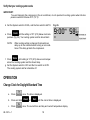
1
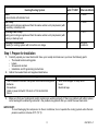
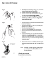
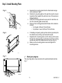
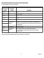
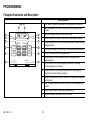
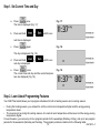
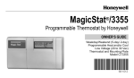
CT3200 Programmable Thermostat
OWNER’S GUIDE
Welcome to the world of comfort and energy savings with your
new Honeywell Programmable Thermostat. Your new thermostat
will automatically control the temperature in your home, keeping
you comfortable while saving energy.
Weekday/Weekend (5-day/2-day)
Programmable Heat and/or Cool
Low Voltage (20 to 30 Vac)
Thermostat and Mounting Plate
Model CT3200
Table of Contents
Installation ..................................................................................................................................................................
Programming..............................................................................................................................................................
Operation....................................................................................................................................................................
Frequently Asked Questions ......................................................................................................................................
Customer Assistance .................................................................................................................................................
Limited Warranty ........................................................................................................................................................
® U.S. Registered Trademark
Copyright © 2003 Honeywell International Inc.
All Rights Reserved
2
12
18
22
23
24
69-1631-1
MERCURY NOTICE
If you are removing an old thermostat that contains mercury in a sealed tube
(Fig. 1), do not place the old thermostat in the trash. Contact your local waste
management authority for instructions regarding recycling and the proper
disposal of the old thermostat.
MERCURY
SWITCH
M3701
Fig. 1.
INSTALLATION
Verify You Have Correct Thermostat
Make sure that the CT3200 is the correct thermostat for your heating/cooling system. Read the compatibility chart
below to determine which system you have. If your system is not compatible with the CT3200, the table recommends
an alternate Honeywell model. If you are unsure what type of thermostat is right for your system, visit us on the Web at
www.honeywell.com/yourhome or call Honeywell Customer Care at 1-800-468-1502.
Compatible
with CT3200?
Heating/Cooling System
Conventional
Single stage systems that include warm air furnaces and hot water.
Yes
Electric Baseboard
Electric-powered heating strips located just above the floor, usually 120 to 240
volts.
No
69-1631—1
2
Alternate Model
CT1950 for 240
volts
Compatible
with CT3200?
Heating/Cooling System
Steam
A steam boiler with radiator heat.
Alternate Model
No
CT3600
Heat Pump
No
Heating and cooling are produced from the same outdoor unit (compressor) with
no auxiliary or backup heat.
CT3600
Multistage Heat Pump
No
Heating and cooling are produced from the same outdoor unit (compressor) with
auxiliary or backup heat.
CT3611
Multistage Conventional
A heating or cooling system with more than one stage.
See your
contractor
No
Step 1. Prepare for Installation
1.
2.
Carefully unpack your new thermostat. Save your receipt and make sure you have the following parts:
• Thermostat and mounting plate
• Labels
• Screws and anchors
• Installation and Programming Instructions
Gather the needed tools and supplies listed below.
Required Tools and Supplies
•
•
•
•
Optional Tools
Two AA alkaline batteries. Honeywell recommends Energizer® •
•
batteries.
•
Screwdriver.
Hand or power drill with 3/16-inch or 7/32-inch drill bit.
Pencil.
3.
Wire cutter/stripper or sharp knife.
Level.
Electrical tape.
Make sure that your heating and cooling systems are working properly. If there is a problem with either system,
call a heating/air conditioning contractor—the problem may persist after you install the new thermostat.
IMPORTANT:
To avoid damaging the compressor in the air conditioner, do not operate the cooling system when the temperature outdoors is below 50°F (10°C).
3
69-1631—1
Step 2. Remove Old Thermostat
Fig. 2.
a.
b.
c.
d.
M20140
Fig. 3.
Turn off power to the heating/cooling system, either at the
furnace or at the fuse/circuit breaker panel.
Remove the cover of your old thermostat (Fig. 2).
Unscrew and remove the old thermostat’s mounting plate
from the wall, but do not disconnect the wires.
Inspect the old thermostat wiring. If wiring meets any of
the following conditions, see special wiring instructions section after Step 7.
•
M19086
Fig. 4.
The old thermostat is a clock thermostat with wires attached
to the C or C1 terminals.
• The old thermostat has six or more wires, excluding wires
attached to C or C1 terminals.
• The old thermostat has three wires.
• There are five wires connected to the old thermostat.
• There are extra wires that are not connected to the old
thermostat.
e. Using enclosed labels, mark wires with letter of terminal it is
attached to on the old thermostat (Fig. 3). Do not label
using colors. If labels do not match letters on old thermostat
terminals, see wiring cross reference table in Special Wiring
Instructions section.
f.
WIRES THROUGH
WALL OPENING
Disconnect the wires from the old thermostat and wrap the
wires around a pencil to keep them from falling back into the
wall.
NOTE:
M20133
Remember, if your old thermostat contains mercury,
you must recycle it. See Mercury Notice for more
recycling information.
✓Check your progress
Your wall should now look like Fig. 4.
69-1631—1
4
Step 3. Install Mounting Plate
Fig. 5.
a.
b.
c.
d.
M20139
Fig. 6.
e.
f.
g.
Separate the mounting plate from the thermostat using a
coin, as shown in Fig 5.
Position the mounting plate on the wall. Be sure the mounting plate is flush against the wall and none of the wires are
trapped behind it.
Level the mounting plate and use a pencil to mark the center of the mounting plate screw holes.
Remove the mounting plate and drill holes at the locations
marked.
• For drywall, drill two 3/16-inch holes.
• For plaster or wood, drill two 7/32-inch holes.
If installing in drywall, gently tap the anchors (provided) into
the drilled holes until they are flush with the wall.
Reposition the mounting plate over the holes, pull the wires
through the wiring opening, and loosely insert the mounting
screws into each of the drilled holes or anchors (Fig. 6).
Make sure the mounting plate is level and tighten the
mounting screws.
M20129
Fig. 7.
✓
Check your progress
R
G
Rc
Y
The mounting plate is now mounted on the wall and should look like
Fig. 7.
W
M20128
5
69-1631—1
Step 4. Set Thermostat for Your Type of Heating System
THERMOSTAT BACK
DISPLAY F
DISPLAY C
3 - ON
3 - OFF
1
2
3
ON
1
2
3
OFF ON
W
C
FUEL SWITCH
F
I
M
P
O
HEATING
RDIP SWITCH FUEL SWITCH
SYSTEM
POSITION
POSITION
T1 - ON 2 - ON
WARM AIR
F
FURNACE
A
HOT WATER OR
1 - OFF 2 - ON
F
HIGH EFFICIENCY N
ELECTRIC
E
FURNACE
T1 - ON 2 - OFF
:
W Y G
E
Y
R
G
RC
M20637
Fig. 8.
a. Use the FUEL SWITCH on the
back of the thermostat to set your
new thermostat for the type of fuel
that your heating system uses: F–
gas or oil, or E–electric.
NOTE: This setting enables
proper fan operation.
RC
C
IMPORTANT:
Setting your thermostat correctly
for your type of heating system
allows it to maintain accurate
temperature control, minimize
swings in the temperature of the
room, and efficiently run the fan.
b. Use DIP switches 1 and 2 on
the back of the thermostat to set
your new thermostat for your type
of heating system. See the Heating System Table on the next
page to find the correct settings.
NOTE: These DIP switches are
factory-set for a warm air, gas, or
oil heating system.
c.
d.
The thermostat is set to display the temperature in degrees Fahrenheit (°F). If you want to display the temperature in degrees Celsius (°C), turn DIP Switch 3 to Off position.
You can install the batteries and program your thermostat now, or you can wait until the thermostat is
mounted on the wall. To install the batteries, see Step 7.To program the thermostat, see the Programming
section.
69-1631—1
6
Heating System Table
DIP Switches
1 and 2
Type of System
Fuel Switch
Warm air, gas, or oil heating system with an efficiency rating under 90%.
(The furnace efficiency rating should be on the furnace.)
Use factory setting
1–On; 2–On
F
High-efficiency furnace such as a 90% or greater AFUE (Average Fuel
Utilization Efficiency) unit
1–Off; 2–On
F
Hot water boiler
1–Off; 2–On
F
Electric furnace
1–On; 2–Off
E
Step 5. Wire Thermostat Terminals
Fig. 9.
a.
b.
G
Y
Hold thermostat as shown in Fig. 9.
Using the labels on the wires, match letter of your old thermostat wire with the corresponding terminal on the back of
your new thermostat.
W
R
NOTE:
If letters on old thermostat terminals do not match letters on
new thermostat terminals, all old wires may not need connecting to new thermostat. See Special Wiring Instructions
section.
M20125
Fig. 10.
c.
5/16 in.
(8 mm)
STRIP
INSERT
STRAIGHT
UNDER
SCREW HEAD
d.
Loosen terminal screws and slip each wire beneath its
matching terminal (Fig 10).
Securely tighten terminals.
END OF WIRE
VISIBLE HERE
M20126
7
69-1631—1
Step 6. Mount Thermostat
Fig. 11.
Fig. 12.
e.
f.
M20131
M20130
69-1631—1
8
Align the tabs at the top of the thermostat
with the tabs at the top of the mounting
plate (Fig. 11).
Press the lower edge of the case to latch
the bottom of the thermostat (Fig. 12)
Step 7. Install the batteries
Fig. 13.
IMPORTANT:
Batteries must be installed for programming and operation of
the thermostat and heating/cooling system. Honeywell recommends using Energizer® batteries.
a.
b.
c.
M1719C
REMOVING
BATTERY
DOOR
Fig. 14.
d.
e.
Make sure that the System switch is set in the OFF position.
Using a coin, open the battery door as shown in Fig. 13.
Install the batteries. Make sure that the positive and negative terminals are oriented correctly as marked inside the
battery case.
Replace the battery door.
Remove the clear plastic label from the digital display.
✓ Check your progress
When the batteries are installed correctly, the digital display flashes all
entries once, then begins to flash a default time and the current
temperature (Fig. 14). The flashing continues until you begin to
program the thermostat. You are now ready to program the thermostat.
See Programming section.
Special Wiring Instructions
Clock thermostat with C or C1 terminals
A clock thermostat has one or two extra wires attached to the C or C1 terminals that allow the clock to operate. These
wires are not used during the installation of your new 3200 Thermostat and must be insulated from each other to avoid
damaging your electrical circuit.
a.
b.
c.
d.
e.
f.
Make sure that power to the heating/cooling system is turned off.
Locate the wires that are connected to the clock terminals marked C or C1.
As you disconnect the wires, do not allow these wires to touch.
Wrap the wires separately, using electrical tape to insulate the wires.
Place the wires where they do not interfere with the operation of the new thermostat.
You will not connect these wires to your 3200 Thermostat.
Continue with the installation.
9
69-1631—1
Six or more wires
If your old thermostat has six or more wires (excluding clock wires attached to the C or C1 terminals), your heating/
cooling system is most likely a variation of a heat pump or multistage system. Your 3200 Thermostat will NOT work
with such systems and should be returned to the place of purchase. See the thermostat compatibility table for
information about which programmable thermostat will work with your system.
Three thermostat wires
If you have three wires for heating only and can operate the fan using the fan ON switch, the 3200 Thermostat will
work with your system. Continue the installation procedure.
If you have a three-wire heating-only system and cannot operate the fan using the fan ON switch, the 3200
Thermostat will probably NOT work with your system. Contact your heating contractor for installation assistance.
Wires that are not connected to old thermostat
If there are extra wires that do not connect to your old thermostat, do not label them. You will not connect these wires
to your new thermostat. Tape off the wires individually with electrical tape and place them where they will not interfere
with the operation of the new thermostat. Continue the installation procedure.
Five wires connected to old thermostat
JUMPER (FACTORYINSTALLED). REMOVE
IF 5-WIRE SYSTEM
Your new thermostat has a factory-installed metal jumper between the R and Rc
terminals (Fig. 15). Remove the jumper before wiring the R and Rc terminals.
Rc
R
M20127
W
Y
G
Fig. 15.
Thermostat C Terminal
This thermostat does not use the C wiring terminal.
69-1631—1
10
Old thermostat terminals that do not match new thermostat terminals
Use the table below to wire the new thermostat.
Connect to New
Thermostat
Terminal
Old Thermostat
Terminal
Description
R, RH, 4, V
R*
Power
Rc, R
Rc*
Power for cooling
W, W1, H
W
Heat
Y, Y1, M
Y
Cooling
G, F
G
Fan
O
Do not continue
installation
Changeover in cool (O terminal) or changeover in heat (B terminal).
You have a single-stage heat pump or zoning system. Select an alternate
thermostat model.
C, X, B
Do not connect
Transformer common.
W2, H2
Do not continue
installation.
Second stage heat (W2, H2) or second stage cooling (Y2).
You have a multistage heating/cooling system. Select an alternate
thermostat model.
B
Y2
*Remove factory-installed jumper between R and Rc terminals in 5-wire systems.
11
69-1631—1
PROGRAMMING
Faceplate Illustration and Description
Descriptions
Fig. 16.
7
6
SYSTEM ON
TEMPORARY
4
2
Set Schedule–Puts the thermostat into programming
mode.
9
3
Set Clock/Day–Sets the clock and day.
10
4
Time Ahead and Back–Sets the time ahead and back.
5
Program periods–Current program period or period being
programmed.
6
Day of the week–Current day or day being programmed.
7
Time–Current time or program time.
8
Temperature–Room temperature or programmed
temperature.
9
SYSTEM ON–An arrow displays when the heating/
cooling system is running.
10
TEMPORARY–An arrow displays when a temporary
override is made to the program.
11
Temp Warmer and Cooler–Sets the temperature warmer
and cooler.
12
Run Program–Returns thermostat to normal operating
mode
13
Hold Temp–Holds a selected temperature.
14
System switch–Selects Cool, Off, Heat.
11
Time
3
Set
clock/Day
Ahead
2
Set
Schedule
Back
1
Fan switch–Selects automatic fan operation or fan on.
8
AM
SET
PM
MO TU WE TH FR SA SU
WAKE LEAVE RETURN SLEEP
5
1
Fan
Auto On
Temp
Warmer
Run
Program
12
Cooler
Hold
Temp
13
System
Cool Off Heat
14
M20141
69-1631—1
12
Step 1. Set Current Time and Day
a.
Press
once.
The time is displayed (Fig. 17).
b.
Press and hold
or
Fig. 17.
until the cur-
rent time is displayed.
c.
Press
again.
Fig. 18.
The day is displayed (Fig. 18).
d.
Press and hold
rent day is displayed.
or
e.
Press
once.
The current time and day and the current temperature are displayed (Fig. 19).
until the cur-
Fig. 19.
Step 2. Learn About Programming Features
Your 3200 Thermostat allows you to program schedules for both a heating season and a cooling season.
•
During the heating season, you will want to set the normal room temperature higher and the energy-saving
temperature lower.
• The reverse is true during the cooling season—the normal room temperature will be lower and the energy-saving
temperature higher.
For each season, you can set up to four program periods for the weekdays (Monday–Friday), and up to two program
periods for the weekends (Saturday and Sunday). The program periods are defined in the following table.
13
69-1631—1
Program Period
Description
When Available
WAKE
The time when you get up and get ready to leave your home. You can Weekdays and weekend
set the system at a comfortable temperature for this period.
LEAVE
The time when you are regularly away from home. You can set up an Weekdays only
energy-saving temperature for this period.
RETURN
The time between returning home and going to bed. You can set the Weekdays only
system at a comfortable temperature for this period.
SLEEP
The time when you are sleeping. You can set up an energy-saving
temperature for this period.
Weekdays and weekend
Programming Tips
•
You do not need to program times and temperatures for all program periods.
If you decide not to program your thermostat, it automatically controls heating at 68°F (20°C), and cooling at 78°F
(26°C), 24 hours a day.
If you decide not to program weekend schedules, the temperature that is programmed for the weekday SLEEP
schedule remains in effect until the next program period, which begins on Monday morning.
•
•
The temperatures cannot be set any higher than 88°F (31°C) or any lower than 45°F (7°C).
When pressing the buttons, use the ball of your finger or a soft pencil eraser. Using sharp fingernails or pencil
points can damage the keypad.
•
If you make an error at any time during programming, press
program period you last programmed.
69-1631—1
14
. Then press
until you reach the
Step 3. Program Heating Schedule
a.
Write in the times and temperatures that you want to program for your heating schedule.
Heating Schedule
Program
Period
WAKE
LEAVE
RETURN
SLEEP
Suggested
Settings
Time
6:00 AM
8:00 AM
6:00 PM
10:00 PM
Temp
70°F (21°C)
62°F (16.5°C)
70°F (21°C)
62°F (16.5°C)
Weekday (Mon–Fri)
Time
Temp
Weekend (Sat–Sun) Time
Temp
b. Set the System switch to HEAT.
Fig. 20.
c. Press
once.
A blank schedule is displayed (Fig. 20).
d. Set the Monday–Friday WAKE time by pressing
Fig. 21.
until the desired time is displayed (Fig. 21).
or
e. Set the Monday–Friday WAKE temperature by pressing
or
until desired temperature is
displayed.
15
69-1631—1
f. Press
to display a blank schedule for the next
Fig. 22.
program period (Fig. 22) and repeat steps d. through f. for
each weekday program period.
g. Press
until the weekend schedule is displayed
Fig. 23.
(Fig. 23).
h. Set the Saturday and Sunday WAKE time by pressing
or
until the desired time is displayed.
i. Set the Saturday and Sunday WAKE temperature by
pressing
or
until desired temperature
displays (Fig. 24).
j. Press
again to display blank schedule for SLEEP
program period and repeat steps h. through j. to set program.
k. Press
69-1631—1
to start the program.
16
Fig. 24.
Step 4. Program Cooling Schedule
a.
Write in the times and temperatures you want to program for your cooling schedule.
Cooling Schedule
Program
Period
WAKE
LEAVE
RETURN
SLEEP
Suggested
Settings
Time
6:00 AM
8:00 AM
6:00 PM
10:00 PM
Temp
78°F (25.5°C)
85°F (29.5°C)
78°F (25.5°C)
82°F (28°C)
Weekday (Mon–Fri)
Time
Temp
Weekend (Sat–Sun) Time
Temp
b.
c.
Set the System switch to COOL.
Repeat steps 3c. through 3k. to program the weekday and weekend cooling schedule.
Step 5. Check System
Verify that your heating system works
a. Set the System switch to HEAT, and the Fan switch to
Fig. 25.
AUTO.
b. Press
until the setting is 10°F (6°C) above room
temperature (Fig. 25). Your heating system should start
and the fan should run after a short delay.
c. Press
until the setting is 10°F (6°C) below room
temperature. Your heating system should shut off.
17
69-1631—1
Verify that your cooling system works
IMPORTANT:
To avoid damaging the compressor in the air conditioner, do not operate the cooling system when the temperature outdoors is below 50°F (10°C).
d. Set the System switch to COOL, and the Fan switch to AUTO.
Fig. 26.
e. Press
until the setting is 10°F (6°C) below room temperature (Fig. 26). Your cooling system and fan should start.
NOTE:
When cooling setting is changed, thermostat can
delay up to five minutes before turning on air conditioner. This delay protects the compressor.
f. Press
until setting is 10°F (6°C) above room temperature.Your cooling system and fan should stop.
g. Set the System switch to OFF and the Fan switch to AUTO.
The cooling system and fan should be off.
OPERATION
Change Clock for Daylight/Standard Time
a.
Press
b.
Press and hold
c.
Press
69-1631—1
once. The time is displayed.
or
until the correct time is displayed.
once. The current time and day and current temperature display.
18
Set Fan and System Switches
The switches on the bottom of the thermostat faceplate control the operation of your fan and the heating and cooling
system. Set the Fan switch first and then set the System switch.
Switch
Fan
Setting
Result
Auto
A single-speed fan turns on automatically with the air conditioner or furnace.
A two-speed fan usually runs on high with the air conditioner and on low with the furnace.
Auto is the normal setting for most homes.
On
The fan runs continuously. Use this setting for improved air circulation during special
occasions or for more efficient air cleaning.
NOTE:
System
In a heat-only system, the fan runs continuously only if the fan wire has been connected to the G terminal on the back of the thermostat.
Cool
The thermostat controls your air conditioning system.
Off
Both the heating and air conditioning systems are off.
Heat
The thermostat controls your heating system.
Replace Batteries
As the batteries run low, your thermostat shows the following in the digital display:
If you see:
Batteries are:
You should:
Flashing “bAt Lo”
Low
Replace the batteries as soon as possible, within the month.
Blank display
Dead
Replace the batteries immediately. Your heating/cooling system is not
operating.
a.
b.
c.
Make sure that the System switch is set to the OFF position.
Open the battery door.
Press on the left side of the batteries to remove them.
NOTE:
If new batteries are inserted within 20-30 seconds of removing old ones, reprogramming is not
needed. If display is blank, batteries are dead or incorrectly installed and reprogramming is needed.
19
69-1631—1
d.
e.
NOTE:
Install new batteries. Make sure that positive and negative terminals are oriented as marked inside battery
case.
Close the battery door and set the System switch to HEAT or COOL.
If “bAt Lo” continues to display after replacing the batteries, set System switch to OFF, insert batteries backward, wait for five to ten seconds, and return batteries to correct orientation. Then reprogram.
IMPORTANT:
Replace batteries once a year to prevent heating/cooling system from shutting down due to lack of battery
power in thermostat. If leaving home for longer than a month, change batteries before leaving.
Override program settings
NOTE:
Make sure the System switch is set to either HEAT or COOL before making any changes to the schedule.
Change the temperature temporarily
Fig. 27.
Press
or
until the desired temperature is
displayed. An arrow is displayed, indicating that the change is
temporary (Fig. 27).
NOTE:
A temporary change to temperature lasts for current
program period only. Heating/cooling schedule you
programmed resumes when next scheduled program period is reached.To cancel temporary
change before next scheduled program period,
press
69-1631—1
.
20
Hold a temperature indefinitely
Fig. 28.
Use the Hold Temp feature when you want to maintain a
constant temperature indefinitely, such as when you go on
vacation.
a.
b.
Press
. “HLd” is displayed (Fig. 28).
Press or until the desired temperature is displayed.
NOTE:
To cancel the hold, press
.
Check the current programmed temperature
Fig. 29.
Press
to display temperature programmed for current
program period. The SET indicator displays briefly along with the
programmed temperature (Fig. 29). The display then returns to the
room temperature.
Check programs
Press
repeatedly to display the times and temperatures
that you programmed.
a.
Press
to resume the program
Cancel a program
a.
Press
(Fig 30).
Fig. 30.
until the desired program is displayed
21
69-1631—1
b.
Press
and
simultaneously.
A blank program schedule is displayed and the program
is canceled (Fig. 31).
Fig. 31.
Change a program permanently
Follow steps for programming heating schedule or programming
cooling schedule.
FREQUENTLY ASKED QUESTIONS
If...
Display does not come on
Then...
•
•
Make sure the batteries are fresh and installed correctly.
Set System switch to Off. Remove batteries and insert backward for five to
ten seconds to reset thermostat. Replace batteries correctly; display should
come on.
Temperature display does not go
•
lower than 45°F (7°C) or higher than
88°F (31°C) during programming.
Temperature limit setting is reached; range is 45°F to 88°F (7°C to 31°C).
Display shows flashing “bAt Lo.”
The batteries are low; replace them as soon as possible.
If “bAt Lo” continues to display after replacing batteries, set System switch
to Off and insert batteries backward for five to ten seconds. Replace
batteries correctly; display should come on.
•
•
Temperature change occurs at wrong •
times
69-1631—1
Check program times for period in question. Be sure AM and PM
indications are correct. Make sure current day and time are correct.
Reprogram if necessary.
22
If...
Heating does not come on
Then...
•
•
•
•
•
•
Cooling does not come on
•
•
•
•
•
•
Check that the System switch is set to Heat.
Check the system fuse or circuit breaker and replace or reset if necessary.
Check for correct wiring and good connections.
If display is blank or displays “bAt Lo,” install fresh batteries.
Allow time for the furnace to heat up and the fan to come on before
checking for heat at the register.
If temperature setting is higher than current room temperature and
SYSTEM ON arrow is displayed, thermostat is operating correctly. Contact
heating contractor for assistance.
Check that the System switch is set to Cool.
Check the system fuse or circuit breaker and replace or reset if necessary.
Check for correct wiring and good connections.
If display is blank or says “bAt Lo,” install fresh batteries.
The thermostat has a built-in time delay on cooling. Allow 5-10 minutes
after changing setting before air conditioner starts.
If temperature setting is lower than room temperature and SYSTEM ON
arrow is displayed, thermostat is operating correctly. Contact ac contractor.
The house is too warm or too cool
•
•
Press RUN PROGRAM to check the current temperature setting.
If desired, change the temperature setting.
Furnace cycles too often or system
cycle length is too short or too long
•
Adjust the screws on the back of the thermostat.
The thermostat current setting does •
not match the display temperature to
within plus or minus 1°
•
•
Plug the wiring hole in the wall behind the mounting plate with insulation to
prevent drafts that might adversely affect thermostat operation.
Be aware that it is normal for the current setting and the displayed room
temperature to differ on occasion.
During recovery from setback or setup, setting and displayed room
temperatures can differ for up to 30 minutes after recovery period.
CUSTOMER ASSISTANCE
Visit us on the Web at www.honeywell.com/yourhome or call Honeywell Customer Care at 1-800-468-1502.
Before you call, please have the following information available:
—
Thermostat model number and serial code (located under the battery cover).
—
Type of heating/cooling system (hot water, warm air, oil, gas, etc.).
—
Number of wires connected to the thermostat.
NOTICE: This equipment is a Class B digital apparatus, that complies with Canadian Radio Interference Regulations, CRC c.1374.
23
69-1631—1
LIMITED WARRANTY
Honeywell warrants this product, excluding battery, to be free from defects in workmanship or materials, under normal use and service,
for a period of one (1) year from the date of purchase by the consumer. If, at any time during the warranty period, the product is
defective or malfunctions, Honeywell shall repair or replace it (at Honeywell’s option) within a reasonable period of time.If the product is
defective,
(i) return it, with a bill of sale or other dated proof of purchase, to the retailer from which you purchased it, or
(ii) package it carefully, along with proof of purchase (including date of purchase) and a short description of the malfunction, and mail it,
postage prepaid, to the following address:
Honeywell Inc. USA
Honeywell Canada:
Dock 4 — MN10-3860
Honeywell Limited/Honeywell Limitée
1885 Douglas Drive North
35 Dynamic Drive
Golden Valley, MN 55422-3992
Scarborough, Ontario M1V 4Z9
This warranty does not cover removal or reinstallation costs. This warranty shall not apply if it is shown by Honeywell that the defect or
malfunction was caused by damage which occurred while the product was in the possession of a consumer.
Honeywell’s sole responsibility shall be to repair or replace the product within the terms stated above. HONEYWELL SHALL NOT BE
LIABLE FOR ANY LOSS OR DAMAGE OF ANY KIND, INCLUDING ANY INCIDENTAL OR CONSEQUENTIAL DAMAGES
RESULTING, DIRECTLY OR INDIRECTLY, FROM ANY BREACH OF ANY WARRANTY, EXPRESS OR IMPLIED, OR ANY OTHER
FAILURE OF THIS PRODUCT. Some states do not allow the exclusion or limitation of incidental or consequential damages, so this
limitation may not apply to you.
THIS WARRANTY IS THE ONLY EXPRESS WARRANTY HONEYWELL MAKES ON THIS PRODUCT. THE DURATION OF ANY
IMPLIED WARRANTIES, INCLUDING THE WARRANTIES OF MERCHANTABILITY AND FITNESS FOR A PARTICULAR PURPOSE,
IS HEREBY LIMITED TO THE ONE YEAR DURATION OF THIS WARRANTY. Some states do not allow limitations on how long an
implied warranty lasts, so the above limitation may not apply to you.
This warranty gives you specific legal rights, and you may have other rights which vary from state to state.
If you have any questions concerning this warranty, please write Honeywell Customer Relations Center, 1985 Douglas Dr. N., Golden
Valley, MN 55422-3992, or call 1-800-468-1502. In Canada, write Retail Products ON30 Honeywell Limited/Honeywell Limitée, 35
Dynamic Drive, Scarborough, Ontario M1V 4Z9.
Automation and Control Solutions
Honeywell International Inc.
1985 Douglas Drive North
Golden Valley, MN 55422
69-1631—1
Honeywell Limited-Honeywell Limitée
35 Dynamic Drive
Scarborough, Ontario
M1V 4Z9
J.S. Rev. 10-03
Printed in U.S.A.
www.honeywell.com/yourhome