1
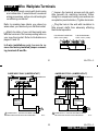
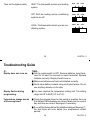
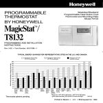
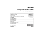
69-0733-3
PROGRAMMING AND INSTALLATION
INSTRUCTIONS
Honeywell/34
Weekday/Saturday/Sunday
PROGRAMMABLE
Programmable Heat and/or Cool
Low Voltage (20 to 30 Vac)Thermostat and Wallplate
THERMOSTAT
Model CT3400/CT3455
TYPICAL ENERGY SAVINGS FOR REPRESENTATIVE CITIES IN THE U.S. AND CANADA
Savings for Once-A-Day
10°F (5°C) decrease
Savings for Twice-A-Day
10°F (5°C) decrease*
Savings for 5°F (3°)
summer increase
Approximate percentage of energy cost savings
30%
28%
26%
24%
22%
20%
18%
16%
14%
12%
10%
8%
6%
4%
2%
Minneapolis
St. Paul
Montreal
Ottawa
Toronto
Edmonton
Regina
Winnipeg
Calgary
Moncton
North Bay
Quebec
St. John's
Halifax
Vancouver
Buffalo
Cleveland
Milwaukee
Denver
Des Moines
Omaha
Salt Lake
City
Boston
Chicago
Detroit
Pittsburgh
Indianapolis
Cincinnati
Kansas City
St. Louis
Columbus
Louisville
New York
Philadelphia Portland
Wash., D C
Seattle
San
Francisco
Dallas
Atlanta
Los Angeles
*Based on 10°F (5°C) decrease—(5°F [3°C] decrease
gives approximately 55 percent of these savings).
J.S. Rev. 4-97
©Honeywell Inc. 1997
Printed in U.S.A.
San Diego
M2416A
Form Number 69-0733—3
TOTAL COMFORT TEMPERATURE MANAGEMENT
WITH ADAPTIVE INTELLIGENT RECOVERY™
Congratulations! You made a smart choice when you purchased your new Honeywell Thermostat.
It’s the smart thermostat that:
■ Keeps you comfortable by automatically calculating exactly when the furnace or air conditioning should go on to have the house at the desired comfort temperature by the time you
wake up or return home.
■ Saves the maximum amount of energy and money by remembering to automatically adjust
the heat or air conditioning when you leave home or go to sleep.
■ Provides the ultimate in comfort and convenience. It comes already programmed, so it’s
your choice—use the preprogrammed schedule or set your own.
We invite you to spend a few minutes reading this manual. You’ll find it answers many of the
questions that will arise as you become familiar and comfortable with your Honeywell thermostat,
the state of the art in home comfort controls.
M3375
Recycling Thermostat
If this thermostat is replacing a control that
contains mercury in a sealed tube, do not
place your old control in the trash. Contact
your local waste management authority for
instructions regarding recycling and the
proper disposal of this control, or of an old
control containing mercury in a sealed tube.
If you have questions, call Honeywell Inc. at
1-800-468-1502.
MERCURY
SWITCH
M3701
Fig. 1. Typical location of a mercury
switch in a thermostat.
Table Of Contents
STEP 1 Prepare For Installation .................................................................................................... 2
STEP 2 Remove Old Thermostat .................................................................................................. 4
STEP 3 Before You Program ......................................................................................................... 6
Install the Batteries .................................................................................................................... 6
Adaptive Intelligent Recovery™ Selection ............................................................................. 7
STEP 4 Program The Thermostat ................................................................................................. 9
STEP 5 Mount Thermostat Wallplate .......................................................................................... 16
STEP 6 Adjust System On-Time, Clock Display, as Required ................................................ 18
STEP 7 Adjust Fan Operation Switch, as Required .................................................................. 20
STEP 8 Wire Wallplate Terminals ............................................................................................... 21
STEP 9 Mount The Thermostat ................................................................................................... 24
STEP 10 Check Thermostat Operation After Programming and Installing ........................... 25
STEP 11 Set the Fan and System Switches .............................................................................. 28
Troubleshooting Guide ................................................................................................................ 30
Index ............................................................................................................................................... 34
Limited One-Year Warranty ......................................................................................................... 36
1
69-0733—3
STEP 1 Prepare For Installation
■ Check Table 1 to make sure this thermostat is compatible with your system. If not, return to retailer.
For more information, call Honeywell Customer Assistance, toll-free 1-800-468-1502.
Table 1. Compatibility Chart.
System Type
Compatible with CT3400/3455
Gas—Standing Pilot
Yes
Gas—Electronic Ignition
Yes
Gas-Fired Boilers
Yes 1
Gas—Millivolt
No
Oil-Fired Boilers
Yes 1
Oil-Fired Furnace
Yes
Electric Furnace
Yes
Electric Air Conditioning
Yes
Baseboard Electric (120/240 line volt)
No
Heat Pumps/Multistage Equipment
No
Not compatible with any 120/240 volt circuit.
1 Compatible with 2-wire Honeywell and Taco zone valves. Not compatible with 3-wire zone valves
or 2-wire White Rodgers no. 1361 valves.
2
69-0733—3
■ Acquire tools and items as needed (below).
CROSS-RECESSED
SCREWDRIVER
HAND OR POWER
DRILL WITH 3/16 INCH
DRILL BIT, IF NEEDED, TO
DRILL HOLES IN WALL
WIRE CUTTER/STRIPPER OR SHARP
KNIFE, IF NEEDED, TO STRIP WIRES
MASKING TAPE, IF
NEEDED, TO LABEL WIRES
AS DISCONNECTED FROM
OLD THERMOSTAT
LEVEL, IF NEEDED, TO LEVEL
THERMOSTAT FOR APPEARANCE
3
STEP 2
M878B
69-0733—3
Remove Old Thermostat
■ Test to make certain that your heating and
cooling systems are working properly. If either
does not work, contact your local heating/air
conditioning dealer. To avoid compressor damage, do not operate the cooling system when
outdoor temperature is below 50°F (10°C).
■ Turn off power to system at the furnace, or
at the fuse/circuit breaker panel.
■ Carefully unpack your new thermostat and
wallplate; save package of screws, instructions
and receipt.
■ Remove the cover from the old thermostat. If
it does not snap off when pulled firmly from the
bottom, check for a screw used to lock on the
cover.
■ Loosen screws holding thermostat to subbase, wallplate or wall, and lift away.
■ Disconnect wires from old thermostat or
subbase. As you disconnect each wire, use
masking tape to label it with the old terminal
designation. If there are
WIRES THROUGH
only two wires, they do
WALL OPENING
not need to be labeled.
Wrap wires around
pencil to keep them
from falling back into
M5136
the wall, as shown.
Replacing a clock thermostat that has C or
C1 clock terminals?
If you are replacing a Honeywell Chronotherm®
Thermostat, you may find one or two wires that
go to the C or C1 clock terminals on the
Chronotherm® Thermostat wiring wallplate. Do
4
69-0733—3
which programmable thermostats will work with
your system, call Honeywell Customer Assistance at 1-800-468-1502.
not allow them to touch, or you can damage your
transformer. Disconnect the wires and wrap
them separately using electrical tape; do not
wrap them together. Place the wires where they
will not interfere with the operation of the new
thermostat. Record the colors and terminal designation labels of the remaining wires.
Three thermostat wires?
If you have three wires for heating only and can
operate the fan using the fan ON switch, this
thermostat will work with your system. However,
some hot water (zoned) heating systems have
three thermostat wires. The thermostat will not
work without installing an isolating relay on these
systems. For details, call Honeywell Customer
Assistance at 1-800-468-1502.
Six or more wires?
If there are six or more wires (excluding clock
wires attached to terminals), you most likely
have a variation of a heat pump or multistage
system. The thermostat is not compatible with
such systems so return the product to the place
of purchase. If you would like information about
5
STEP 3
69-0733—3
Before You Program
If you insert new batteries within 20 to 30 seconds of removing the old ones, you will not have
to reprogram the thermostat. However, if the
display is blank, the batteries are dead or
incorrectly installed. In this case, you will
have to re program. See pages 13 through 15
to reprogram. If you do not reprogram, the
factory-preproBACK OF THERMOSTAT
grammed
settings will be
in effect, as
shown in
chart on
pages 11
and 12.
Install the Batteries
IMPORTANT: Three AA alkaline batteries are
included with the thermostat. Batteries must
be installed for programming and operation of
the thermostat and heating/cooling system.
■ Install the batteries in back of the thermostat
as shown, making sure positive (+) terminals all
face toward the right.
As the batteries are running low, a REPL BAT
indicator will flash for 1 to 2 months before batteries run out completely. Replace the batteries
as soon as possible after the indicator starts
flashing.
INSTALL 3 AA ALKALINE BATTERIES AS SHOWN,
POSITIVE (+) TERMINALS TOWARD RIGHT.
6
M2589
69-0733—3
Adaptive Intelligent Recovery™
Selection
IMPORTANT: Although the thermostat has a
low battery indicator, replace the batteries
once a year to prevent leakage and to prevent
the thermostat and heating/cooling system
from shutting down due to lack of battery
power.
Before you program your thermostat, you must
decide if you want to leave the thermostat at
the factory-set Adaptive Intelligent Recovery™
setting, or adjust it to conventional recovery. If
you choose conventional recovery, adjust screw
3A (on the back of the thermostat) by turning out
one turn.
As a precaution when leaving home for longer
than a month, change batteries before you leave
to prevent system from shutting down due to lack
of battery power.
With Adaptive Intelligent Recovery™, your home
gradually reaches the comfort temperature you
set at the exact time programmed into the thermostat to achieve maximum energy savings and
comfort.
Use fresh alkaline batteries; nonalkaline batteries do not last as long, and may leak, causing
damage to the thermostat or the wall surface.
We recommend Energizer® batteries.
7
69-0733—3
More about Adaptive Intelligent Recovery™…
for the thermostat to adjust to the weather, your
lifestyle, home construction and heating/cooling
system.
This thermostat is actually a small but powerful
computer. When calculating the exact time to turn
on your furnace or air conditioner, it considers: (1)
air temperature, (2) the temperature of
the wall and (3) when you want the comfort
temperature established.
With conventional recovery, the programmed time
marks the start of the time your furnace or air
conditioner comes on to start recovery; therefore,
you should program the start time to be earlier
than the desired comfort time. The best starting
time varies as the seasons change, but 30
minutes is a good head start time to use.
During recovery, the thermostat increases the
control temperature gradually and turns the equipment on and off several times before reaching
your comfort time to save energy by avoiding
overshooting the comfort temperature. You can
see the current control temperature anytime during recovery by pressing the CURRENT SETTING key.
NOTE: If you adjust screw
PM
TUE
3A for conventional reDAYTIME
covery, a ■ indicator
appears in the lower INDICATES
THERMOSTAT IS SET FOR
right corner of the ther- CONVENTIONAL RECOVERY
M2483
mostat display as a reminder that you are no longer using the Adaptive Intelligent Recovery™ feature.
SET
PT
This smart control learns from experience. Each
day it checks how closely it hit the target and
adjusts the recovery start time accordingly. It
normally takes four to eight days after installation
8
69-0733—3
STEP 4
Program The Thermostat
After the batteries are installed, the thermostat
can be easily programmed in your hand before
it is installed on the wall.
work or school. (This will be a higher temperature during heating season, or a lower
temperature during cooling season.)
DAYTIME is the time period you can set for an
energy-saving temperature while you are
away at work or school. (This will be a lower
temperature during heating season, or a
higher temperature during cooling season.)
EVENING is the time period you want the
house at a comfortable temperature for
activities before bedtime. (Again, higher
heat or lower cool.)
NIGHT is the time period you can set for an
energy-saving temperature while you are
sleeping. (Again, lower heat or higher cool.
Although for more comfortable sleeping,
some people choose not to raise the cool
temperature during the night.)
If you would prefer to program the thermostat
after it is installed on the wall, skip to page 16,
and return later to this programming section.
The following personal programming chart
(pages 11 and 12) may be helpful when planning your program schedule of time and temperature settings for various times of the day.
Four time periods are available—MORNING,
DAYTIME, EVENING and NIGHT. Each
period has its own setting key.
MORNING is the time period you want the
house at a comfortable temperature when
you get up and while you get ready for
9
You will set one schedule for weekdays, one for
Saturday, and another for Sunday, because
your requirements will probably be different for
each.
Before programming, remove the clear plastic
overlay covering the display.
When pressing the keys, use the ball of your
finger or a soft pencil eraser. Use of sharp fingernails or pencil points can damage the keypad.
Fill in the times and temperatures you desire for
weekdays, Saturday, Sunday. The factory-preprogrammed time and temperature settings are
shown in parentheses. If you decide not to
program the thermostat, it automatically controls to these settings. The thermostat requires a
time and temperature program for the MORNING period. You can program DAYTIME and
EVENING, or leave them blank. You can also
change NIGHT or cancel it (see page 15), as you
please.
PROGRAMMING
69-0733—3
If at any time during programming you make an
error, just press the RUN PROGRAM key, and
continue again at the step where you left off.
10
69-0733—3
Personal Programming Chart
Weekday Program
PERIOD
MORNING
DAYTIME
EVENING
NIGHT
HEATING 1
TEMPERATURE
START
TIME
COOLING 1
TEMPERATURE
(6:00
AM)
_____________________
(70°F [21°C])
_____________________
______________
______________
______________
______________
(78°F [26°C])
_____________
_____________
(10:00
PM)
_____________________
(60°F [16°C])
_____________________
(78°F [26°C])
_____________________
Saturday Program
PERIOD
MORNING
DAYTIME
EVENING
NIGHT
START
TIME
1
HEATING
TEMPERATURE
1
COOLING
TEMPERATURE
(6:00
AM)
_____________________
(70°F [21°C])
_____________________
(78°F [26°C])
_____________________
______________
______________
______________
______________
_____________
_____________
(10:00
PM)
_____________________
(60°F [16°C])
_____________________
(78°F [26°C])
_____________________
11
69-0733—3
Sunday Program
PERIOD
MORNING
DAYTIME
EVENING
NIGHT
1
START
TIME
HEATING 1
TEMPERATURE
COOLING 1
TEMPERATURE
(6:00
AM)
_____________________
(70°F [21°C])
_____________________
(78
°F [26°C])
_____________________
______________
______________
______________
______________
_____________
_____________
(10:00
PM)
_____________________
(60°F [16°C])
_____________________
(78
°F [26°C])
_____________________
The temperatures cannot be set any higher than 88°F (31°C) or any lower than 45°F (7°C).
NOTE: The factory-preprogrammed time and temperature settings are shown in parentheses.
PROGRAMMING
12
69-0733—3
When programming your new thermostat, use this guide. Batteries are required for programming
and operation.
SET PRESENT DAY
Set
Press and release Day/Time
Present
then
SET PRESENT TIME
Set
Press and release Day/Time
Present
then
until present day shows.
Day
a
Time
until present time shows.
HEATING PROGRAM
With system switch at HEAT, press and release
Morning
. Use
a
Time
a
and
Temp
to
program Mon-Fri MORNING time and temperature. Repeat using DAYTIME, EVENING, NIGHT
keys.
For Saturday, press
Day
a
Temp
to SAT. Press and release
Morning
a
; use
Time
and
to program Saturday morning time and temperature. Repeat using DAYTIME, EVENING,
NIGHT keys.
For Sunday, press
Day
to SUN. Repeat steps as you did for SAT.
13
69-0733—3
COOLING PROGRAM
The times you set for heating remain the same for cooling; you only need to program the temperatures.
With system switch at COOL, press and release
Morning
. Use
Temp
a
to program Mon-Fri
MORNING temperature. Repeat using DAYTIME, EVENING, NIGHT keys.
For Saturday, press
program
Day
to SAT. Press and release
Morning
; use
Temp
a
to
Saturday morning temperature. Repeat using DAYTIME, EVENING, NIGHT keys.
For Sunday, press
Day
to SUN. Repeat steps as you did for SAT.
After programming, adjust fan and system switches as desired.
Press and release
a
Press on
Run
Program
to start the program.
to move number back; press on
PROGRAMMING
14
to move number ahead.
69-0733—3
For operating or making changes, use this guide.
a
Temp
Temporarily Change temperature for current period only—
; TEMPORARY indicator
shows on display, and cancels itself at next scheduled change. To cancel sooner, you may
Run
press Program
.
a
Hold a temperature indefinitely (such as on vacation)—
Run
on display; to cancel, press Program
.
Check current temperature setting—
Current
Setting
,
Hold
Temp
Hold appears
Temp
.
Daytime
Cancel a program—Press and hold
,
Morning cannot be cancelled (only changed).
Evening
or
Night
three seconds to cancel.
Permanently Change a program—Repeat steps under Heating Program (page 13) or Cooling
Program (page 14), as applicable.
Run
Program
Return to normal program or start program—
a
Press on
to move number back; press on
.
to move number ahead.
15
69-0733—3
STEP 5 Mount Thermostat Wallplate
■ Position wallplate on wall. Level the wallplate for appearance only. Use a pencil to
mark the two mounting holes that best fit the
application.
WALL
WIRES THROUGH
WALL OPENING
WALL
ANCHORS
(2)
MOUNTING
1
HOLES (3)
MOUNTING
SCREWS (2)
WALLPLATE
1
USE THE TWO MOUNTING HOLES THAT BEST FIT APPLICATION.
M5932A
16
69-0733—3
INSTALLATION
■ Remove wallplate from wall, and drill
3/16 inch holes in wall (if drywall) as marked.
For firmer material such as plaster or wood,
drill 7/32 inch holes. Gently tap anchors
(provided) into drilled holes until flush with
the wall.
LEVEL
■ Reposition wallplate over holes, pulling
wires through wiring opening. Loosely insert
two mounting screws into holes.
M611B
■ Level for appearance only; thermostat
functions properly even when not level.
Tighten mounting screws.
17
69-0733—3
STEP 6 Adjust System On-Time, Clock Display,
As Required
■ The thermostat on-time is factory-set for a
warm air, gas or oil heating system. If you are
installing it on another type of system, the ontime must be adjusted accordingly by setting
screws 1A and 1B on the back of the thermostat, using the heating system table in the
illustration as a guide. The system on-time
should be optimized with the type of system to
minimize room temperature swings. Setting the
screw out one turn means turning the screw
approximately 360° counterclockwise, or about
one complete turn.
First, turn both screws in completely, then adjust for system type:
• Hot Water or High Efficiency—Set at the
Gravity Air/Water setting (1A—out one turn,
1B—out one turn).
• Gas/Oil Warm Air—Set at the Hot Water or
High Efficiency setting (1A—leave in, 1B—
out one turn).
• Electric Warm Air—Leave at the Gas/
Oil Warm Air setting (1A—leave in, 1B—
leave in).
In the unlikely event that you want longer furnace on-time, readjust screws 1A and/or 1B as
follows:
18
69-0733—3
INSTALLATION
RECOVERY
SELECTION
IMPORTANT: When using a high efficiency
furnace such as a 90% or greater AFUE
(Average Fuel Utilization Efficiency) unit,
leave screw 1A in and screw 1B out one turn.
3A
IN
ADAPTIVE
INTELLIGENT TM (FACTORY SETTING)
OUT
1 TURN
CONVENTIONAL
BACK OF THERMOSTAT
■ The thermostat is set to display the time as
a 12-hour clock and the temperature in degrees
Fahrenheit. If a 24-hour clock (e.g., military
time) or degrees Celsius readings are desired,
adjust screws 2A and 2B as necessary using
the illustration as a guide.
3A 1A 1B
2A 2B
■ For an explanation of the Recovery Selection screws (3A), see pages 7 and 8.
SYSTEM
1A
GRAVITY
AIR/WATER
OUT
1 TURN
OUT
1 TURN
1B
HOT
WATER
OR HIGH
EFFICIENCY
(90%+AFUE)
IN
OUT
1 TURN
GAS/OIL
WARM AIR
IN
IN
(FACTORY SETTING)
ELECTRIC
WARM AIR
OUT
1 TURN
2A
DISPLAY
12 hr./ °F
2B
OUT
OUT
(FACTORY SETTING)
24 hr./ °F
IN
OUT
24 hr./ °C
IN
IN
12 hr./ °C
OUT
IN
19
IN
M 618A
69-0733—3
STEP 7 Adjust Fan Operation Switch, As Required
BACK OF THERMOSTAT
■ The thermostat fan operation switch is factory-set in the left (NON ELEC) position. This is
the correct setting for most systems. If your
system is an electric furnace, set the switch to
the right (ELEC) position. The ELEC position
allows the fan to turn on immediately with the
heating or cooling system if the G terminal is
connected to a fan relay.
NOTE: Either the switch must be set before the
batteries are installed, or the left battery
must be removed to access the switch.
4A
FAN OPERATION SWITCH
(SHOWN IN NON ELEC POSITION)
20
M619C
69-0733—3
INSTALLATION
STEP 8 Wire Wallplate Terminals
NOTE: All wiring must comply with local codes
and ordinances. If unsure about household
wiring procedures, call your local heating/air
conditioning contractor.
■ Loosen the terminal screws and slip each
wire beneath its matching terminal. Either
straight or wraparound wiring connections are
acceptable (see illustration). Tighten terminals.
Refer to masking tape labels you placed on
wires when you removed your old thermostat.
■ Plug the hole in the wall with insulation to
help prevent drafts from adversely affecting
thermostat operation.
■ Match the letter of your old thermostat wire
with the terminal of the corresponding letter on
your new thermostat. Refer to illustrations on
pages 22 and 23.
FOR WRAPAROUND–
STRIP 7/16 IN. (11MM)
FOR STRAIGHT INSERTION–
STRIP 5/16 IN. (8MM)
In 5-wire installations only, be sure to remove the factory-installed jumper connecting terminals R and Rc.
M2486
21
69-0733—3
4-WIRE HEAT/COOL (JUMPER INTACT)
2-WIRE HEAT-ONLY (JUMPER INTACT)
THERMOSTAT
THERMOSTAT
W G
R RC
R RC
W G
Y
HEATING
RELAY OR
VALVE COIL
HEATING
RELAY OR
VALVE COIL
FAN
RELAY
Y
COOLING
CONTACTOR
COIL
1
1
1 POWER SUPPLY. PROVIDE DISCONNECT MEANS
AND OVERLOAD PROTECTION AS REQUIRED.
1 POWER SUPPLY. PROVIDE DISCONNECT MEANS
AND OVERLOAD PROTECTION AS REQUIRED.
M612A
22
M614A
69-0733—3
INSTALLATION
3-WIRE HEAT ONLY (JUMPER INTACT)
5-WIRE HEAT/COOL (JUMPER REMOVED)
THERMOSTAT
W G
HEATING
RELAY OR
VALVE COIL
R RC
THERMOSTAT
Y
R RC
W G
HEATING
RELAY OR
VALVE COIL
FAN
RELAY
Y
COOLING
CONTACTOR
COIL
FAN
RELAY
1
1
1
1 POWER SUPPLY. PROVIDE DISCONNECT MEANS
AND OVERLOAD PROTECTION AS REQUIRED.
1 POWER SUPPLY. PROVIDE DISCONNECT MEANS
AND OVERLOAD PROTECTION AS REQUIRED.
M 615A
M613A
23
69-0733—3
STEP 9 Mount The Thermostat
AM
MON
DAYTIME
HEAT ON
A.
ENGAGE TABS BETWEEN
TOP OF THERMOSTAT
AND WALLPLATE
B.
C.
SWING COVER OPEN FOR
CHECKOUT AND PROGRAMMING
PRESS
LOWER EDGE
OF CASE TO
LATCH
AM
MON
DAYTIME
Set
HEAT ON
Current
Setting
Day
Present
Day Time
Hold
Temp
Morning
Daytime
Temp
Run
Program
Night
Evening
Time
On Auto
Heat On Cool
Fan
M5143
24
69-0733—3
INSTALLATION
STEP 10 Check Thermostat Operation After Programming
And Installing
HEATING
Do not check heating system operation
by jumpering thermostat terminals at
the primary control, such as the gas
valve, zone valve, oil burner control.
This will damage the thermostat. Instead, you could jumper R and W wires
at the thermostat.
HEAT
FAN
OFF
COOL
ON
AUTO
Temp
M2472
25
M2472
NOTE: When cooling setting is changed,
thermostat may delay up to five minutes before turning on the air conditioner. This delay protects the compressor.
HEAT
FAN
OFF
COOL
ON
Temp
Temp
26
Press up arrow of key until the setting is
about 10°F (6°C) above room temperature. Heating should start and the fan
should run after a short delay (immediately if fan operation switch is set in
ELEC position).
69-0733—3
Temp
COOLING
To avoid possible compressor damage,
do not operate the cooling system when
outside temperature is below 50°F
(10°C). See compressor manufacturer
instructions for further information.
Move the system switch to HEAT and
the fan switch to AUTO.
Press down arrow of key until setting is
about 10°F (6°C ) below room temperature. The heating equipment should shut
off.
Move the system switch to COOL and
the fan switch to AUTO.
AUTO
Press down arrow of key until setting is
about 10°F (6°C) below room temperature. The cooling equipment and fan
should start.
Press up arrow of key until the setting is
about 10°F (6°C) above room temperature. The cooling equipment and fan
should stop.
69-0733-3
HEAT
FAN
OFF
ON
COOL
AUTO
Move the system switch to OFF and the
fan switch to ON. The fan should run
continuously. When the fan switch is in
the AUTO position, fan cycles with the
heating or cooling system.
27
69-0733—3
STEP 11 Set The Fan And System Switches
First set the fan switch.
FAN ON: The fan runs continuously. Use for
improved air circulation during special occasions or for more efficient electronic air cleaning. (In a heat-only system, fan runs continuously only if fan relay is connected to the
thermostat.)
FAN AUTO: Normal setting for most homes.
A single-speed fan turns on automatically
with the air conditioner or furnace. A twospeed fan usually runs on high with the air
conditioner and on low with the furnace.
Exception: If fan operation switch on back of
thermostat is set to the ELEC (right) position
(see page 20), fan operates with furnace
only.
28
FAN
FAN
ON
ON
AUTO
AUTO
69-0733—3
Then set the system switch.
HEAT: The thermostat controls your heating
system.
HEAT
OFF
COOL
OFF: Both the heating and air conditioning
systems are off.
HEAT
OFF
COOL
COOL: The thermostat controls your air conditioning system.
HEAT
OFF
COOL
29
69-0733—3
Troubleshooting Guide
IF…
Display does not come on.
THEN…
■ Set the system switch to OFF. Remove batteries. Insert backward for at least five seconds to reset thermostat. Replace
batteries correctly. Display should come on.
■ Make sure batteries are fresh and installed correctly.
■ Gently clean battery contacts using a soft pencil eraser. Do not
use anything abrasive on the clips.
Display flashes during
programming.
■ You have reached the temperature setting limit. The setting
range is 45°F to 88°F (7°C to 31°C).
Temperature change occurs
at the wrong times.
■ Check the program times for the period in question. Be sure
that AM and PM indications are correct. Make sure the current
day and time are correct. Reprogram if necessary.
■ If you left the thermostat set for Adaptive Intelligent Recovery™,
the start times will occur before your programmed comfort
periods.
30
69-0733—3
Heating does not come on.
■ Check that switch on thermostat is set to HEAT.
■ Check the system fuse or circuit breaker and replace or reset if
necessary. If display is blank or displays REPL BAT, install
fresh batteries.
■ Check for correct wiring and good connections.
■ Jumper wires R and W. If heat does not come on, contact your
heating dealer.
■ If temperature setting is higher than current temperature, and
HEAT ON is displayed, contact Honeywell Customer Assistance at 1-800-468-1502.
Cooling does not come on.
■ Check that switch on thermostat is set to COOL.
■ Check the system fuse or circuit breaker and replace or reset if
necessary. If display is blank or displays REPL BAT, install
fresh batteries.
■ Check for correct wiring and good connections.
31
69-0733—3
■ Jumper wires Rc and Y. If cooling does not come on, contact
your cooling dealer.
■ The thermostat has a built-in time delay on cooling. Allow up to
ten minutes after changing the setting before the air conditioner
starts.
■ Make sure outdoor disconnect is energized (on).
■ If temperature setting is lower than current temperature, and
COOL is displayed, move system switch from COOL to OFF for
ten minutes. After ten minutes, return the switch to the COOL
position. If your air conditioner comes on, this indicates your
compressor may have reached its high limit temperature
protection and shut down. If your air conditioner does not
come on after ten minutes and COOL is displayed, contact
Honeywell Customer Assistance at 1-800-468-1502.
■ If 2- or 4-wire installation, verify that R-Rc jumper is installed.
The house is too warm or
too cool.
■ Press CURRENT SETTING to check the current temperature
setting.
■ If desired, change the temperature setting. See page 15.
32
69-0733—3
HEAT ON is displayed, but
no heat is coming from
the registers.
■ Allow time for the furnace to heat up and the fan to come on
before checking for heat at the register. Note that on most gas
and oil systems, the fan is not controlled by the thermostat, but
by another control, which may account for the delay.
The system cycle length
is too short or too long.
■ Readjust according to instructions on pages 18 and 19.
The thermostat's current
setting does not match the
display temperature to
within ± 1°.
■
Incorrect room temperature
showing on thermostat
display.
■
Check that the wiring hole in the wall behind the wallplate has
been plugged with insulation to prevent drafts that might
adversely affect thermostat operation.
Be aware that it is normal for the current setting and display
temperature to differ occasionally.
■
Make sure the hole behind the thermostat is plugged with
insulation to help prevent drafts from adversely affecting the
thermostat operation.
■
The thermosat is factory-calibrated and cannot be adjusted.
33
69-0733—3
Index
Adaptive Intelligent
Recovery™ ....................... 7,8
Batteries, installation .............. 6
Batteries, replacement ........ 6,7
Blinking display ....................... 6
Canceling programs ............. 15
Change temperature ............. 15
Checking current setting ....... 15
Clock display ........................ 19
Conventional Recovery ....... 7,8
Cooling
temperatures ........ 9,11,12,14
Current setting ...................... 15
Customer Assistance............ 35
Day ........................................ 13
DAYTIME .................... 13,14,15
Energy-saving
temperature ......................... 9
EVENING .................... 13,14,15
Fan operation switch ............ 20
Fan switch ............................. 29
Flashing display ...................... 6
Heating
temperatures ........ 9,11,12,13
Hold temperature .................. 15
MORNING ....................... 13,14
NIGHT ......................... 13,14,15
Operation .............................. 15
Period keys ............................. 9
Personal programming
chart .............................. 11,12
Preprogrammed
schedule ............... 9,10,11,12
Programming steps ......... 13,14
Replacing batteries .............. 6,7
Saturday
program ......... 10,11,12,13,14
Set cooling temperatures ..... 14
Set present day .................... 13
Set present time ................... 13
34
Set fan switch ....................... 28
Set cooling temperatures ..... 14
Set heating temperatures ..... 13
Setting limits .................... 11,12
Sunday
program ......... 10,11,12,13,14
System switch ....................... 29
Switch,fan ............................. 28
Switch, system ...................... 29
Table of Contents ................... 1
Temporary program
changes ........................... 15
Time ...................................... 13
Time period .............. 9,10,11,12
Troubleshooting ..... 30,31,32,33
Warranty ............................... 36
Weekday
program ........... 9,10,11,13,14
69-0733—3
NOTICE: This equipment is a Class B digital
apparatus, which complies with Canadian
Radio Interference Regulations, CRC c.1374.
Toll-free Customer Assistance
For all questions concerning this thermostat,
please read and follow the instructions. If additional assistance is needed, call Honeywell Customer Assistance toll-free at 1-800-468-1502,
Monday-Friday, 7:00 a.m. - 5:30 p.m., Central
time.
Before you call, please have the following information available—thermostat model number and date code, type of heating/cooling system (e.g., hot water, warm air, oil, gas, etc.), and
number of wires connected to the thermostat.
35
69-0733—3
Limited One-Year Warranty
Honeywell warrants this product, excluding battery, to be free from defects in the workmanship or materials, under normal use and service, for a
period of one (1) year from the date of purchase by the consumer. If, at any time during the warranty period, the product is defective or
malfunctions, Honeywell shall repair or replace it (at Honeywell’s option) within a reasonable period of time.
If the product is defective,
(i) return it, with a bill of sale or other dated proof of purchase, to the retailer from which you purchased it, or
(ii) package it carefully, along with proof of purchase (including date of purchase) and a short description of the malfunction, and mail it,
postage prepaid, to the following address:
Honeywell Inc.
in Canada: Honeywell Limited/Honeywell Limitee
Return Goods Department
Product Services ON30
1050 Berkshire Lane
155 Gordon Baker Road
Plymouth, MN 55441-4437
North York, Ontario M2H 3N7
This warranty does not cover removal or reinstallation costs. This warranty shall not apply if it is shown by Honeywell that the defect or
malfunction was caused by damage which occurred while the product was in the possession of a consumer.
Honeywell’s sole responsibility shall be to repair or replace the product within the terms stated above. HONEYWELL SHALL NOT BE LIABLE
FOR ANY LOSS OR DAMAGE OF ANY KIND, INCLUDING ANY INCIDENTAL OR CONSEQUENTIAL DAMAGES RESULTING, DIRECTLY OR
INDIRECTLY FROM ANY BREACH OF ANY WARRANTY, EXPRESS OR IMPLIED, OR ANY OTHER FAILURE OF THIS PRODUCT. Some
states do not allow the exclusion or limitation of incidental or consequential damages, so this limitation may not apply to you.
THIS WARRANTY IS THE ONLY EXPRESS WARRANTY HONEYWELL MAKES ON THIS PRODUCT. THE DURATION OF ANY IMPLIED
WARRANTIES, INCLUDING THE WARRANTIES OF MERCHANTABILITY AND FITNESS FOR A PARTICULAR PURPOSE, IS HEREBY
LIMITED TO THE ONE YEAR DURATION OF THIS WARRANTY. Some states do not allow limitations on how long an implied warranty lasts, so
the above limitation may not apply to you.
This warranty gives you specific legal rights, and you may have other rights which vary from state to state.
If you have any questions concerning this warranty, please write our Customer Assistance Department, Honeywell Inc., 1885 Douglas Dr. N.,
Golden Valley, MN 55422-3992, or call 1-800-468-1502, Monday-Friday, 7:00 a.m. to 5:30 p.m., Central time. In Canada, write Retail Products
ON30 Honeywell Limited/Honeywell Limitee,155 Gordon Baker Road, North York, Ontario M2H 3N7.
36
69-0733—3