1
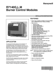
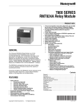
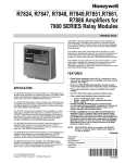
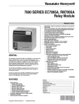
7800 SERIES EC7810A, EC7820A Relay Modules SPECIFICATION DATA FEATURES • • • • • • • • • GENERAL The Honeywell EC7810/EC7820A Relay Module is a microprocessor-based integrated burner control for automatically fired gas, oil or combination fuel single burner atmospheric (EC7810A) or atmospheric with fan (EC7820A) applications. The EC7810A/EC7820A system consists of the relay module, wiring subbase, amplifier and purge card. The optional keyboard display module (KDM) can be mounted on the relay module or on the face of a panel door. The KDM can also be mounted remotely from the panel if this is approved for the application. The EC7810/EC7820 is programmed to provide a level of safety, functional capability and features beyond the capacity of conventional controls. The basic functions of the EC7810/EC7820A include automatic burner sequencing, flame supervision, system status indication, system or self-diagnostics and troubleshooting. ® U.S. Registered Trademark Copyright © 1998 Honeywell Inc. • All Rights Reserved • • • Safety features: — Interlock check. — Dynamic AMPLI-CHECK™ — Closed loop logic test. — Dynamic input check. — Dynamic safety relay test. — Dynamic self-check logic. — Expanded safe-start check. — Internal hardware status monitoring. — Low Fire Start Switch test. — Tamper resistant timing and logic. Ignition attempts: 1 or 5. Selectable by model number. Access for external electrical voltage checks. Application flexibility. Dependable, long-term operation provided by microcomputer technology. First-out annunciation and system diagnostics provided by a 2 row by 20 column vacuum fluorescent display (VFD) located on the KDM (optional). Five sequence information light emitting diodes (LED)with symbols for Power, Pilot, Flame, Main and Alarm (see Fig. 1). Interchangeable plug-in flame amplifiers. Nonvolatile memory; EC7810/EC7820 retain history files and sequencing status after loss of power. Remote reset (subject to application approval; optional). Remote mounting of KDM (subject to application approval). Burner control data available on the optional KDM: — Flame signal strength. — Hold status. — Lockout/alarm status. — Sequence status. — Sequence time. — Total cycles of operation. — Total hours of operation. — Fault history providing the six most recent faults: • Cycles of operation at the time of the fault. • Fault message and code. • Hours of operation at the time of the fault. • Sequence status at the time of the fault. • Sequence time at the time of the fault. — Diagnostic information: • Device type. • Flame amplifier type. • Flame failure response time (FFRT). • Manufacturing code. • On/off status of all digital inputs and outputs. • Selected prepurge time. • Software revision and version of relay module and optional KDM. • Status of configuration jumper. • Status of Run/Test Switch. 66-2040 7800 SERIES EC7810A, EC7820A RELAY MODULES BURNER CONTROL 1 127 127 1 133 REMOVE ONLY FOR TERMINAL TEST ACCESS. M12821 Fig. 1 Mounting dimensions of relay module and wiring subbase in millimeters only. SPECIFICATIONS Table 1A. EC7810A Terminal Ratings. Terminal No. Abbreviation Description Ratings G Flame Sensor Ground a Earth G Earth Grounda N Line Voltage Common (Neutral) 3 L1 Line Voltage Supply (L1) 220-240 Vac (+10%/-15%), 50/60 Hz (±10%). b 4 AL Alarm (Normally Open) 220/230/240 Vac, 1A, 10A inrush for 5000 cycles. 6 RT Limits and Burner Control 220/230/240 Vac, 5A (maximum). 7 LD2 Airflow Switch Input 220/230/240 Vac, 1 mA. 8 PV1 Pilot Valve 1 (interrupted) 220/230/240 Vac, 4A at PF = 0.5, 20A inrush.c 9 MV Main Fuel Valve 220/230/240 Vac, 4A at PF = 0.5, 20A inrush.c 10 IGN Ignition 220/230/240 Vac, 4A at PF = 0.2.c Flame Signal 136 to 220 Vac, current limited. F(11) 13 COM Firing Rate Common 220/230/240 Vac, 4A at PF = 0.5.d 14 MOD Firing Rate Modulate 220/230/240 Vac, 4A at PF = 0.5.d 16 Control Voltage 220-240 Vac (+10%/-15%). 17 ES2 Preignition Interlock Input 220/230/240 Vac, 1 mA. 18 ES1 Low Fire Switch Input 220/230/240 Vac, 1 mA. 20 LOS Lockout Input 220/230/240 Vac, 1 mA. 21 PV2 Pilot Valve 2 (Intermittent) 220/230/240 Vac, 4A at P.F.= 0.5, 20A inrush. c 22 SHTR Shutter 220-240 Vac, 0.25A.e a See Table 2. b 2000 VA maximum connected load to 7800 SERIES Relay Module Assembly. c Total load current, excluding burner/boiler motor and firing rate outputs cannot exceed 5A, 25A inrush. d Can also be 24 Vac, 3A at PF = 0.5. e 220-240 Vac to 120 Vac, 10 VA (minimum) stepdown transformer (not provided) required to drive shutter. 66-2040 2 7800 SERIES EC7810A, EC7820A RELAY MODULES Table 1B. EC7820A Terminal Ratings. Terminal No. Abbreviation Description Ratings G Flame Sensor Ground a Earth G Earth Grounda N Line Voltage Common (Neutral) 3 AL Alarm (Normally Open) 220/230/240 Vac, 1A, 10A inrush for 5000 cycles. 4 FAN Burner/Blower Motor 220/230/240 Vac, 4A at P.F. = 0.5, 20A inrush. 5 L1 Line Voltage Supply (L1) 220-240 Vac (+10%/-15%), 50/60 Hz (±10%).b 6 RT Limits and Burner Control 220/230/240 Vac, 5A (maximum). 7 LD2 Airflow Switch Input 220/230/240 Vac, 1 mA. 8 PV1 Pilot Valve 1 (interrupted) 220/230/240 Vac, 4A at P.F. = 0.5, 20A inrush.c 9 MV Main Fuel Valve 220/230/240 Vac, 4A at P.F. = 0.5, 20A inrush.c 10 IGN Ignition 220/230/240 Vac, 4A at P.F. = 0.2.c Flame Signal 135 to 220 Vac, current limited. F(11) 13 COM Firing Rate Common 220/230/240 Vac, 4A at P.F. = 0.5.d 14 MOD Firing Rate Modulate 220/230/240 Vac, 4A at P.F. = 0.5.d 16 Control Voltage 220-240 Vac (+10%/-15%). 17 ES2 Preignition Interlock Input 220/230/240 Vac, 1 mA. 18 ES1 Low Fire Switch Input 220/230/240 Vac, 1 mA. 20 LOS Lockout Input 220/230/240 Vac, 1 mA. 21 PV2 Pilot Valve 2 (Intermittent) 220/230/240 Vac, 4A at P.F.= 0.5, 20A inrush. c 22 SHTR Shutter 220-240 Vac, 0.25A.e a See Table 2. b 2000 VA maximum connected load to 7800 SERIES Relay Module Assembly. c Total load current, excluding burner/boiler motor and firing rate outputs cannot exceed 5A, 25A inrush. d Can also be 24 Vac, 3A at PF = 0.5. e 220-240 Vac to 120 Vac, 10 VA (minimum) stepdown transformer (not provided) required to drive shutter. Table 2. Recommended grounding practices. Ground type Earth ground (subbase and relay module). Recommended Practice 1. 2. 3. Signal ground (KDM, Data ControlBus Module™, Communications Interface ControlBus™ Module). Use to provide a connection between the subbase and the control panel of the equipment. Earth ground must be capable of conducting enough current to blow the 20A fuse (or breaker) in the event of an internal short circuit. Use wide straps or brackets to provide minimum length, maximum surface area ground conductors. If a leadwire must be used, use 14 AWG copper wire. Make sure that mechanically-tightened joints along the ground path are free of nonconductive coatings and protected against corrosion on mating surfaces. Use the shield of the signal wire to ground the device to the signal ground terminal 3(c) of each device. Connect the shield at both ends of the daisy chain to earth ground. 3 66-2040 7800 SERIES EC7810A, EC7820A RELAY MODULES Table 3. Sequence Timing for Normal Operation. Device Initiate Standby Purge or Waiting Preignition First Safety Time Pilot Stab. Main Trial Time*** Main Stab. Run Ignition Attempts EC7810A1027 2 sec * ** 3 sec 5 or 10 sec 5 sec 5 or 8 sec 5 sec * 1 EC7810A1035 2 sec * ** 3 sec 5 or 10 sec 5 sec 5 or 8 sec 5 sec * 5 EC7820A1026 2 sec * ** 3 sec 5 or 10 sec 5 sec 5 or 8 sec 5 sec * 1 EC7820A1034 2 sec * ** 3 sec 5 or 10 sec 5 sec 5 or 8 sec 5 sec * 5 * Standby and Run can be an infinite period. ** Waiting Time is determined by the ST7800A Purge Card selected. *** Second Safety Time is Main Trial Time plus Flame Failure Response Time. Electrical Ratings (See Tables 1A and 1B): Voltage and Frequency: 220 to 240 Vac (+10%/-15%), 50/60 Hz (±10%). Keyboard Display Module (Optional): 13 Vdc peak fullwave rectified (+20%/-15%). Power Dissipation: Relay Module: 10W maximum. KDM: 3W maximum. Maximum Total Connected Load: 2000 VA. Fusing (Total Connected Load): 20A, type FRN or equivalent. Oil Approvals: EC7810A1027: DIN-5F104/96. EC7820A1026: DIN-5F105/96. EN298: “Automatic gas burner systems for gas burners and gas burning appliances with or without fans.” Please note the following to comply with EN60730 for remote mounting of the KDM and/or remote reset. It is necessary to provide electrical separation using insulation at least equivalent to double or reinforced insulation. Accomplish this by either: • Optically isolating the communication and/or remote reset lines from the control cabinet or • Providing physical separation from the communication and/or remote reset lines using electrical conduit and a remote display cover assembly (part no. 204718A) or other suitable enclosure that meets IP40 class of protection. Environmental Ratings: Ambient Temperatures: Operating: -40°C to 60°C (-40°F to 140°F). Storage: -40°C to 66°C. (-40°F to 150°F). Humidity: 85% RH continuous, noncondensing. Vibration: 0.5G environment. Dimensions: See Fig. 1 and 2. Mounting: Q7800A Wiring Subbase for Panel Mount: To meet EN60730 requirements, mount the relay module in a secured panel which meets IP40 class of protection. Weight: Relay Module: 0,730 kg unpacked. KDM: 0,113 kg unpacked. Required Components: Plug-in Flame Signal Amplifier: See Table 2. ST7800A Plug-in Purge Timer Cards: Selectable from two seconds to 30 minutes. Q7800A Wiring Subbase. IMPORTANT Flame Detection System available for use with EC7810/EC7820. Select your plug-in Flame Signal Amplifier and applicable Flame Detector from Table 4. Accessories: Keyboard Display Modules (KDM) (Optional): S7800A1001 English language. S7800A1035 French language. S7800A1043 German language. S7800A1050 Italian language. S7800A1068 Spanish language. S7800A1118 Katakana (Japanese) language. S7800A1126 Portuguese language. S7800B1009 Chinese language. Approvals: This product complies with the following European directives: Gas Appliance Directive (90/269/EEG). Low Voltage Directive (73/23/EEG). EMC Directive (89/336/EEG). GASTEC (CE-63AP3070/1). Factory Mutual: J.I.0Y0A9.AF. 66-2040 4 7800 SERIES EC7810A, EC7820A RELAY MODULES Miscellaneous: S7820A1007 Remote Reset Module. 203541 Data ControlBus Connector, 5-wire. 203765 Remote Display Mounting Bracket. 221729 Relay Module Dust Cover. 204718A Keyboard Display Module Cover, NEMA 4, clear. 204718B Keyboard Display Module Cover, NEMA 1, clear. 204718C Keyboard Display Module Cover, NEMA 4, clear with reset button. 205321B Flush Display Mounting Kit. 221818A Extension Cable, display, (1524 mm). 221818C Extension Cable, display, (3048 mm). 123514A Rectification Flame Simulator. 203659 Ultraviolet Flame Simulator. 203968A Remote Display Power Supply, 13 Vdc, plug-in. Communications: Q7700B1004 Network Interface Unit with universal 100 to 250 Vac, 50/60 Hz external power supply, external modem required. QS7800A1001 ControlBus Module, standard. QS7800B1000 ControlBus Module, multidrop. QS7800C1009 ControlBus Module, data acquisition modules. QS7800D1008 ControlBus Module, Armstrong. QS7800E1007 ControlBus Module, Pulsafeeder. QS7850A1006 ControlBus Module, General Purpose Interface. ZM7850A1001 Combustion System Manager™ Software. ZM7850B1000 SYSNet™ Facilities Integration Software. S7810A1009 Data ControlBus™ Module (if no KDM is used). S7810B1007 Data ControlBus™ Module, Multi-Drop Switch Module. Table 4. Flame Detection System Plug-in Flame Signal Amplifiers Type Color Self-Checking Rectification Green No R7847A No Ultraviolet Purple Blue Model Applicable Flame Detectors Flame Failure Response Time Fuel Type Models 1 or 2 sec maximum. Gas Rectifying Flame Rod Holdersa C7004, C7007, C7011. Complete Assemblies: C7008, C7009, Q179. R7847A 1 or 2 sec maximum. Oil Rectifying Photocell C7003, C7010, C7013, C7014.b Dynamic Ampli-Check™ R7847B 1 or 2 sec maximum. Gas Rectifying Flame Rod Holdersa C7004, C7007, C7011. Complete Assemblies: C7008, C7009, Q179. Dynamic Ampli-Check™ R7847B 1 or 2 sec maximum. Oil Rectifying Photocelld C7003, C7010, C7013, C7014.b No c R7849A 1 or 2 sec maximum. Gas, oil Ultraviolet (Minipeeper) C7027,C7035, C7044d. Dynamic Ampli-Check™ R7849B 1 or 2 sec maximum. Gas, oil Ultraviolet (Minipeeper) C7027,C7035, C7044d. Dynamic Self-Check R7861A c,f 1 or 2 sec maximum. Gas, oil Ultraviolet C7061.g Dynamic Self-Check R7886A c,f 2 sec maximum. Gas, oil, coal Ultraviolet (Adjustable Sensitivity) C7076.g a Order flame rod separately; see holder instructions. b Use only Honeywell Photocell part number 38316. c Dynamic Self-Check ultraviolet amplifiers should be used only on burners that cycle on-off at least once every 24 hours. Appliances with burners that remain on continuously for 24 hours or longer should use C7061A Flame Detector with R7861A Amplifier. d C7027, C7035 and C7044 Flame Detectors should be used only on burners that cycle on-off at least once every 24 hours. Appliances with burners that remain on continuously for 24 hours or longer should use C7061A Flame Detector with R7861A Amplifier as ultraviolet flame detection system. e Circuitry tests the flame signal amplifier at least 12 times a minute during burner operation and shuts down the boiler if the amplifier fails. f Circuitry tests all electronic components in the flame detection system (amplifier and detector) 12 times a minute during burner operation and shuts down the burner if the detection system fails. g A 220/240 Vac to 120 Vac 10 VA step-down transformer (not provided) must be used to drive the shutter. 5 66-2040 7800 SERIES EC7810A, EC7820A RELAY MODULES 66-2040 6 7800 SERIES EC7810A, EC7820A RELAY MODULES 7 66-2040 7800 SERIES EC7810A, EC7820A RELAY MODULES Home and Building Control Honeywell Inc. Honeywell Plaza P.O. Box 524 Minneapolis MN 55408-0524 Home and Building Control Honeywell Limited-Honeywell Limitée 155 Gordon Baker Road North York, Ontario M2H 3N7 Honeywell Latin American Region 480 Sawgrass Corporate Parkway Suite 200 Sunrise FL 33325 Honeywell Europe S.A. 3 Avenue du Bourget 1140 Brussels Belgium 66-2040 G.R. 3-98 Printed in U.S.A. on recycled paper containing at least 10% post-consumer paper 8 fibers. Honeywell Asia Pacific Inc. Room 3213-3225 Sun Hung Kai Centre No. 30 Harbour Road Wanchai Hong Kong www.honeywell.com