1
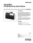
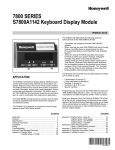
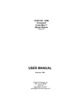
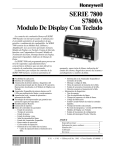
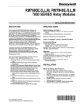
QS7800B Network Interface ControlBus™
Module for Multi-Dropping
7800 SERIES Relay Modules
PRODUCT DATA
APPLICATION
The QS7800B Network Interface ControlBus™ Module allows
remote monitoring and diagnostics of multi-dropped 7800
SERIES Relay Modules.
FEATURES
• Up to six ControlBus™ Modules per Network Interface
Unit. (Maximum of 222 multi-dropped subnetworks per
Q7700 Network Interface Unit).
• Up to 31 multi-dropped 7800 SERIES subnetworks per
QS7800B ControlBus™ Module without using an
RS-485 repeater.
• Up to 61 multi-dropped 7800 SERIES subnetworks per
QS7800B ControlBus™ Module using an RS-485
repeater.
• Local and remote annunciation of 7800 SERIES Relay
Module faults.
• Personal computer user interface.
• Microsoft® Windows™ based Combustion System
Manager® user interface.
• Modular construction.
Contents
Application ........................................................................
Features ...........................................................................
Specifications ...................................................................
Installation ........................................................................
Ordering Information ........................................................
Wiring ...............................................................................
Building a Multi-Drop Network ..........................................
® U.S. Registered Trademark
Copyright © 2002 Honeywell • All Rights Reserved
1
1
2
2
2
3
6
65- 0227- 2
QS7800B NETWORK INTERFACE CONTROLBUS™ MODULE FOR MULTI-DROPPING 7800 SERIES RELAY MODULES
SPECIFICATIONS
Models: QS7800B1000 Network Interface ControlBus™
Module for use with the S7810B Multi-Drop Switch Module
and Q7700A1014 and Q7700B1004 Network Interface
Unit.
Electrical Ratings:
ControlBus™ Communication.
Current Draw: 75 mA.
Electrical Connectors: ControlBus™ Three-Prong Electrical
Connector.
Environmental Ratings:
Ambient Temperature:
Operating: 32°F to 130°F (0°C to 54°C).
Storage: -30°F to +150°F (-34°C to +66°C).
Humidity: Operating 85 percent relative humidity, continuous,
noncondensing.
Vibration: Continuous 0.5G.
Enclosure: NEMA 1.
Dimensions: See Fig. 1.
IMPORTANT
This equipment complies with the requirements in
part 15 of FCC rules for a Class A computing device.
Operation of this equipment in a residential area can
cause unacceptable interference with radio and
television reception that requires the operator to take
whatever steps are necessary to correct
interference.
Warning: This equipment generates, uses, and can radiate
radio frequency energy, and if not installed and used in
accordance with the Instructions Manual, may cause
interference with radio communication. It has been tested and
found to comply with the limits for a Class A computing device
pursuant to Subpart J of Part 15 of FCC Rules, which are
designed to provide reasonable protection against such
interference when operated in a commercial environment.
Operation of this equipment in a residential area is likely to
cause interference, in which case, user at their own expense
will be required to take whatever measures may be required
to correct the interference. Any unauthorized modification of
this equipment may result in the revocation of the owner’s
authority to continue its operation.
Weight: 8 oz (unpacked).
Accessories:
221237/1698 Cover Assembly, Q7700 Network Interface Unit.
221240/1698 Cover Assembly, Q7700 Electrical Enclosure,
Network Interface Unit.
202433 Slot Inserts, ControlBus™ Slots Base Unit.
200603 ControlBus™ Electrical Connector.
Approvals:
Underwriters Laboratories Inc: File No. MP268, Guide No.
MCCZ2.
Canadian Standards Association: LR80141 .
Federal Communications Commission: Part 15, Class A Emissions, Part 68.
FCC: Registration Number HS92SJ-10735-DT-E.
Canadian Department of Communication: CS-03, Certification
Number 573-3459A.
Canadian EMI: This digital apparatus does not exceed the
Class A limits for radio noise emission from digital apparatus
set out in the Radio Interference Regulations of the Canadian
Department of Communications.
Le présent appareil numérique n’émet pas de bruits
radioélectriques dépassant les limites applicables aux
appareils numériques de la Classe A prescrites dans le
Règlement sur le brouillage radioeléctrique édicté par le
ministère des Communications du Canada.
INSTALLATION
When Installing this Product...
1.
2.
Read these instructions carefully. Failure to follow them
could damage the product or cause a hazardous
condition.
Check the ratings given in the instructions and on the
product to make sure the product is suitable for your
application.
ORDERING INFORMATION
When purchasing replacement and modernization products from your TRADELINE® wholesaler or distributor, refer to the
TRADELINE® Catalog or price sheets for complete ordering number.
If you have additional questions, need further information, or would like to comment on our products or services, please write or
phone:
1. Your local Home and Building Control Sales Office (check white pages of your phone directory).
2. Home and Building Control Customer Relations
Honeywell, 1885 Douglas Drive North
Minneapolis, Minnesota 55422-4386
In Canada—Honeywell Limited/Honeywell Limitée, 35 Dynamic Drive, Scarborough, Ontario M1V 4Z9.
International Sales and Service Offices in all principal cities of the world. Manufacturing in Australia, Canada, Finland, France,
Germany, Japan, Mexico, Netherlands, Spain, Taiwan, United Kingdom, U.S.A.
65-0227—2
2
QS7800B NETWORK INTERFACE CONTROLBUS™ MODULE FOR MULTI-DROPPING 7800 SERIES RELAY MODULES
3.
4.
5.
6.
Installer must be a trained, experienced service
technician.
Check out the product after installation, as provided in
the Q7700 Network Interface Unit instructions, form 632278 and S7810B instructions, form 65-0228.
Make sure that only the manufacturer makes repairs.
If trouble develops, disconnect the equipment from the
modem and determine the cause of the fault.
Reconnect only when the problem is corrected.
6.
WIRING
WARNING
.Electrical Shock Hazard.
Can cause severe injury, death or equipment
damage.
Disconnect power supply before beginning installation
to prevent electrical shock and equipment damage.
More than one power supply disconnection can be
involved.
Wiring Requirements
WARNING
Humidity
Install the Network Interface Unit where the relative humidity
never reaches the saturation point. The Network Interface
Unit is designed to operate in an 85 percent relative humidity
continuous noncondensing moisture environment.
Condensing moisture can result in improper operation.
1.
Vibration
Do not install the Network Interface Unit where it can be
subjected to excessive vibration in excess of 0.5G continuous
maximum vibration.
2.
Weather
For installation dimensions, see Fig. 1.
3.
4.
5.
QS7800B
Terminals
Signal
Mounting the Network Interface Plug-in Card
2.
Electrical Shock Hazard.
Can cause severe injury, death or equipment
damage.
1. Wiring must comply with all applicable codes,
ordinances and regulations.
2. Refer to Fig. 6 for proper system wiring.
3. Do not plug or unplug any Network Interface Unit
ControlBus™ Module or electrical connectors with
the power on. Make sure that power is off to protect
against equipment damage.
All wiring must comply with all applicable electrical
codes, ordinances, and regulations.
Recommended wire size and type for ControlBus™
communication is shielded 22 AWG twisted pair cable
(Belden 8723 or equivalent). Terminal identification
numbers and letters are shown in Table 1.
Table 1. QS7800B and S7810B Terminals
and Identification.
The Network Interface Unit is not designed to be weather
tight. When installed outdoors, provide protection for the
Network Interface Unit.
1.
a. Allow for an additional 2-1/2 inches (64 mm)
minimum below the Network Interface Unit for
electrical connector installation.
b. Allow for an additional 1-1/2 inches (38 mm)
minimum on each side for electrical housing cover
insertion and wiring.
Remove the ControlBus™ Module using the wire loop;
grasp the ControlBus™ Module firmly and pull the
module from the Network Interface Unit.
Mount the ControlBus™ Module in the Network
Interface Unit (see Fig. 2). Do not mount the Network
Interface Unit with the Interface ControlBus™ Module
edge connector slots facing down.
Insert the ControlBus™ Module with the electrical
connector facing out from the Network Interface Unit.
Grasp the ControlBus™ Module and align the plug-in
edge card with the connector in the bottom of the
Network Interface Unit.
Firmly insert the ControlBus™ Module into the Network
Interface Unit.
Select a location that can support the Network Interface
Unit. Be sure to allow clearances for servicing, installing
and removing the wiring compartment cover, Network
Interface Unit cover, electrical connectors and
ControlBus™ Modules.
Multi-Drop Data+
a
7
Multi-Drop Data-
b
8
Multi-Drop Ground
c
6
3.
4.
Wire Routing:
a. Do not route the ControlBus™ cable in conduit with
line voltage circuits.
b. Do not route the ControlBus™ cable close to the
ignition transformer.
c. Route the ControlBus™ cable outside of conduit if
properly supported and protected from damage.
d. Route the ControlBus™ cable so that all devices are
connected in a daisy chain configuration. See Fig. 6.
Maximum wire lengths can be 4000 ft (1219 m) for the
ControlBus™ RS-485 interface under ideal conditions.
Procedure
1.
2.
3.
3
S7810B
Terminals
Refer to Fig. 6 for proper wiring.
Be sure that power is removed from the control panel by
opening the main disconnect before beginning wiring to
the electrical connectors. More than one disconnection
can be involved.
Select the location of the Network Interface Unit to be
mounted:
65-0227—2
QS7800B NETWORK INTERFACE CONTROLBUS™ MODULE FOR MULTI-DROPPING 7800 SERIES RELAY MODULES
a. Near a phone line.
b. Within 4000 ft (1219 m) of all Relay Modules
connected to the Network Interface Unit.
c. Within 50 ft (15 m) of the personal computer
connected to the 25-pin RS-232 port of the Network
Interface Unit.
4. Mount the Network Interface Unit and insert the
ControlBus™ Module into the Network Interface Unit
slot, see Fig. 2 and 5.
• Route the ControlBus™ cable so that all devices are
connected in a daisy chain configuration. It is
recommended that the QS7800B ControlBus™ Module be
at one end of the daisy chain.
5. Connect L1, L2 and Ground (GND) to the pigtails
(Q7700A only).
6. Insert the plug-in cards into the open slots of the
Network Interface Unit, starting with slot one.
7. Install the covers, power wiring compartment and
Network Interface Unit.
8. Connect the serial port of the modem to the 9-pin
RS-232 connector of the Network Interface Unit (see
Fig 4).
9. Connect the serial port of the personal computer to the
25-pin RS-232C port on the Network Interface Unit for
local personal computer application, see Fig. 3.
10. Do not exceed 600 mA current draw, six card maximum,
total capacity of the plug-in cards. Refer to the
ControlBus™ Module device label and this specification
for individual loads.
11. Recheck all wiring with Fig. 6.
12. Restore power to the Network Interface Unit.
3-29/32
(99)
NETWORK
INTERFACE
UNIT
25-PIN
RS-232C
CONNECTOR
M7432B
Fig. 3. RS-232 Interface insertion
(serial communications).
NETWORK
INTERFACE UNIT
CONTROLBUS™
PLUG-IN MODULE
9-PIN RS-232
CONNECTOR
RS-232C CONNECTOR
(SERIAL COMMUNICATIONS)
1 (25)
M7433B
Fig. 4. Modem insertion, Network Interface Unit.
4-21/32 (118)
M2093
Fig. 1. QS7800B Network Interface ControlBus™ Module
dimensions in in. (mm).
NETWORK
INTERFACE
UNIT
CONTROLBUS™
MODULE
ELECTRICAL
CONNECTOR
CONTROLBUS
RS-485 CONNECTOR
EDGE
CONNECTOR
NETWORK
INTERFACE UNIT
M7436B
Fig. 5. ControlBus™ RS-485 interface insertion.
M7437B
Fig. 2. ControlBus™ Module mounting.
65-0227—2
CONTROLBUS™
MODULE
4
QS7800B NETWORK INTERFACE CONTROLBUS™ MODULE FOR MULTI-DROPPING 7800 SERIES RELAY MODULES
NETWORK INTERFACE UNIT
PLUG-IN
2
A
10
B
PLUG-IN
C
5
UNIVERSAL
POWER
SUPPLY
9
6
TO LOCAL
SYSTEM
8
1
7
L1
POWER
SUPPLY
SYSTEM 2
3
87654321
L2
6
TO LOCAL
SYSTEM
GND
9
7800 SERIES
RELAY MODULE
7
+ –
4
GND
INPUT
87654321
S7810B MULTI-DROP
SWITCH MODULE
RS-485
REPEATER
7800 SERIES
RELAY MODULE
OUTPUT
+ –
S7810B MULTI-DROP
SWITCH MODULE
GND
9
6
TO LOCAL
SYSTEM
8
7
87654321
S7810B MULTI-DROP
SWITCH MODULE
9
7800 SERIES
RELAY MODULE
1
POWER SUPPLY. PROVIDE DISCONNECT MEANS AND OVERLOAD PROTECTION AS REQUIRED. Q7700A1014, 120V, 50/60 HZ; Q7700B1004,
UNIVERSAL POWER SUPPLY, 100 TO 250V, 50/60 HZ.
2 CONNECT PIGTAIL LEADWIRES (Q7700A ONLY):
BLACK—L1
WHITE—L2
GREEN—GROUND
3
MULTI-DROP RS-485 COMMUNICATION BUS. UP TO 31 S7810B MULTI-DROP SWITCH MODULES (SUBNETWORKS) CAN BE CONNECTED TO A SINGLE
QS7800B CONTROLBUS™ MODULE WITHOUT AN RS-485 REPEATER. UP TO 61 S7810B MULTI-DROP SWITCH MODULES (SUBNETWORKS) CAN BE
CONNECTED TO A SINGLE QS7800B CONTROLBUS™ MODULE WITH AN RS-485 REPEATER.
4 INSTALL THE REPEATER BETWEEN THE 30TH AND 31ST SUBNETWORKS.
5 UP TO SIX QS7800B CONTROLBUS™ MODULES CAN BE INTERFACED WITH THE NETWORK INTERFACE UNIT. MAXIMUM OF 222 MULTI-DROP
SUBNETWORKS CAN BE INTERFACED WITH A SINGLE Q7700 NETWORK INTERFACE UNIT.
6
LOCAL SYSTEM (SUBNETWORK). REFER TO S7810B MULTI-DROP SWITCH MODULE INSTRUCTIONS, FORM 65-0228, FOR WIRING INSTRUCTIONS.
7
THE SUBNETWORKS MUST BE WIRED IN A DAISY CHAIN CONFIGURATION. IT IS RECOMMENDED THAT THE QS7800B CONTROLBUS™ MODULE
BE AT ONE END OF THE DAISY CHAIN.
8
22 AWG (OR LARGER) TWISTED PAIR SHIELDED CABLE (BELDEN 8723 OR EQUIVALENT) IS RECOMMENDED. CABLE SHIELD MUST BE GROUNDED
AT EACH END.
9
MULTI-DROP COMMUNICATION BUS TERMINATION RESISTORS:
A. WITHOUT RS-485 REPEATER: MODULES AT THE CLOSEST AND FARTHEST END OF THE DAISY CHAIN REQUIRE TERMINATION RESISTORS. INSTALL
A 120 OHM, 1/4 WATT, RESISTOR BETWEEN TERMINALS a AND b of the QS7800B CONTROLBUS™ MODULE. INSTALL A 120 OHM, 1/4 WATT, RESISTOR
BETWEEN TERMINALS 7 AND 8 OF THE LAST S7810B MULTI-DROP SWITCH MODULE IN THE DAISY CHAIN.
B. WITH RS-485 REPEATER: WHEN AN RS-485 REPEATER IS USED, TWO DAISY CHAIN CONFIGURATIONS ARE EFFECTIVELY FORMED. MODULES AT
THE CLOSEST AND FARTHEST END OF EACH DAISY CHAIN REQUIRE TERMINATION RESISTORS. INSTALL A 120 OHM, 1/4 WATT, RESISTOR BETWEEN
TERMINALS a AND b OF THE QS7800B CONTROLBUS™ MODULE. INSTALL A 120 OHM, 1/4 WATT, RESISTOR BETWEEN INPUT TERMINALS DATA+ AND
DATA- OF THE RS-485 REPEATER. INSTALL A 120 OHM, 1/4 WATT, RESISTOR BETWEEN OUTPUT TERMINALS DATA+ AND DATA- OF THE RS-485 REPEATER.
INSTALL A 120 OHM, 1/4 WATT, RESISTOR BETWEEN TERMINALS 7 AND 8 OF THE LAST S7810B MULTI-DROP SWITCH MODULE IN THE SECOND DAISY CHAIN.
M11347A
10 FOR Q7700B NETWORK INTERFACE UNIT.
Fig. 6. Multi-drop wiring.
5
65-0227—2
QS7800B NETWORK INTERFACE CONTROLBUS™ MODULE FOR MULTI-DROPPING 7800 SERIES RELAY MODULES
BUILDING A MULTI-DROP NETWORK
Each subnetwork includes one 7800 SERIES controller with
or without an S7800 Keyboard Display Module and/or an
S7830 Expanded Annunciator. An S7810B1007 Multi-Drop
Switch Module is required in each subnetwork. See Fig. 6 for
wiring information.
Guidelines
The subnetwork addressing in the Q7700 Network Interface
Unit (NIU) is not contiguous. It is divided into two blocks,
containing 198 and 24 addresses, respectively. A maximum
multi-drop configuration would include 222 subnetworks (198
plus 24) on a single Q7700 NIU. Because the 24 subnetworks
are not contiguous, connect them to a separate Q7700 NIU
slot.
Subnetworks can be spread evenly (balanced) across the NIU
slots. This will help to speed communications.
It is recommended that the multi-drop network be built starting
with slot number 1 of the NIU, according to the guidelines
above.
One QS7800B ControlBus™ Module card supports up to 31
multi-drop subnetworks without using an RS-485 repeater. If
an RS-485 repeater is used, up to 61 multi-drop subnetworks
can be supported by one QS7800B card. The RS-485
repeater must be installed between the 30th and 31st
subnetwork.
Record the serial number and physical location of each
S7810B Multi-Drop Switch. This data will be useful when
commissioning the ZM7850 Combustion System Manager
(CSM) software. (Reference CSM manual, form 65-0102, for
CSM commissioning.)
Examples
Network with Maximum of 198 Subnetworks:
NIU Slot Numbers
1
2
3
4
5
6
Total
Number of Subnetworks
61
61
61
15
Open
Open
198
Subnetworks Balanced
33
33
33
33
33
33
198
The open NIU slots can be used for other QS7800 ControlBus™ Module Cards.
Network with Maximum of 222 Subnetworks:
NOTE: For networks that have more than 198 subnetworks,
the last NIU card slot must have the 199th through
222nd subnetwork attached to it.
NIU Slot Numbers
1
2
3
4
5
6
Total
Number of Subnetworks
61
61
61
15
24
Open
222
Subnetworks Balanced
40
40
40
39
39
24
222
The open NIU slot can be used for other QS7800 ControlBus™ Module Cards.
65-0227—2
6
7
65-0227—2
Automation and Control Solutions
Honeywell International
Honeywell Europe S.A.
Honeywell
1985 Douglas Drive North
Golden Valley, MN 55422
Control Products
Honeywell Building
17 Changi Business Park Central 1
Singapore 486073
3 Avenue du Bourget
1140 Brussels
Belgium
Honeywell Limited-Honeywell Limitée
35 Dynamic Drive
Scarborough, Ontario
M1V 4Z9
65-0227—2 G.R. Rev. 01-02
Printed in U.S.A. on recycled
paper containing at least 10%
post-consumer paper fibers.
Honeywell Latin American
Region
480 Sawgrass Corporate Parkway
Suite 200
Sunrise FL 33325
www.honeywell.com