1
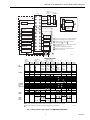
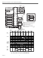
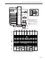
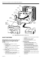
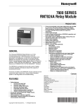
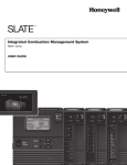
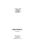
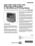
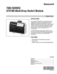
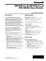
RM7800E,G,L,M; RM7840E,G,L,M
7800 SERIES Relay Modules
INSTALLATION INSTRUCTIONS
APPLICATION
SPECIFICATIONS
The Honeywell RM7800/RM7840 Relay Modules are
microprocessor-based integrated burner controls for
automatically fired gas, oil, or combination fuel single burner
applications. The RM7800/RM7840 Relay Modules are used
for UL/CSA On/Off, UL/CSA Modulating, and FM/IRI
Modulating burner applications. The RM7800/RM7840 system
consists of a Relay Module. Keyboard Display Modules
(standard with RM7800), Dust Cover (standard with RM7840),
Subbase, Amplifier, and Purge Card. Options include
Personal Computer Interface, DATA CONTROLBUS
MODULE™, Remote Display Mounting, First-Out Expanded
Annunciator and Combustion System Manager™ Software.
Electrical Ratings, see Table 3:
Voltage and Frequency: 120 Vac (+10/-15%), 50 or 60 Hz
(±10%).
Power Dissipation: RM7800/RM7840: 10W maximum.
Functions provided by the RM7800/RM7840 include
automatic burner sequencing, flame supervision, system
status indication, system or self-diagnostics and
troubleshooting. The RM7800/RM7840 is a solid state
replacement for the electromechanical R4140 Automatic
Programming Control.
This document provides installation and static checkout
instructions. Other applicable publications are:
65-0084:Q7800A,B 22-Terminal Wiring Subbase Product
Data.
65-0089:ST7800A Plug-In Purge Timer Installation
Instructions.
65-0090:S7800A Keyboard Display Module Product Data.
65-0091:S7810A Data ControlBus Module™ Product Data.
65-0095:S7820 Remote Reset Module Product Data.
65-0097:221729C Dust Cover Packing Sheet.
65-0101:S7830 Expanded Annunciator Product Data.
65-0109:R7824, R7847, R7848, R7849, R7851, R7861,
R7886 Flame Amplifiers for the 7800 SERIES Product
Data.
65-0131:221818A Extension Cable Assembly Product
Data.
65-0228:7800 SERIES Multi-Drop Switch Module Product
Data.
65-0229:7800 SERIES RELAY MODULES Checkout and
Troubleshooting Product Data.
65-0249:S7810M ModBus™ Module Product Data.
® U.S. Registered Trademark
Copyright © 2002 Honeywell • All Rights Reserved
Maximum Total Connected Load: 2000 VA.
Fusing: 15A maximum, Type SC or equivalent Fast Blow.
Environmental Ratings:
Ambient Temperature:
Operating: -40°F to +140°F (-40°C to +60°C).
Storage: -40°F to +150°F (-40°C to +66°C).
Humidity: 85% relative humidity continuous, noncondensing.
Vibration: 0.5G environment.
Approvals:
Underwriters Laboratories Inc. Listed: File No. MP268,
Guide No. MCCZ.
Canadian Standards Association Certified: LR9S329-3.
Factory Mutual Approved: Report No. J.I.1V9A0.AF.
IRI Acceptable.
Federal Communications Commission, Part 15,
Class B—Emissions.
INSTALLATION
When Installing this Product...
1.
2.
3.
4.
Read these instructions carefully. Failure to follow
them could damage the product or cause a hazardous
condition.
Check the ratings given in the instructions and marked
on the product to make sure the product is suitable for
the application.
Installer must be a trained, experienced, flame
safeguard service technician.
After installation is complete, check out the product
operation as provided in these instructions.
66- 1085- 3
RM7800E,G,L,M; RM7840E,G,L,M 7800 SERIES RELAY MODULES
Location
WARNING
Fire or Explosion Hazard.
Can cause property damage, severe injury,
or death.
To prevent possible hazardous burner operation, verify
safety requirements each time a control is installed on
a burner.
Humidity
Install the relay module where the relative humidity never
reaches the saturation point. The relay module is designed to
operate in a maximum 85 percent relative humidity
continuous, noncondensing, moisture environment.
Condensing moisture may cause a safety shutdown.
Vibration
WARNING
Do not install the relay module where it could be subjected to
vibration in excess of 0.5G continuous maximum vibration.
Electrical Shock Hazard.
Can cause serious injury or death.
Disconnect the power supply before beginning
installation. More than one power supply disconnect
may be required.
Weather
IMPORTANT
1. Wiring connections for the relay modules are unique;
therefore, refer to Fig. 2, 3, 4, or the correct
Specifications for proper subbase wiring, and
sequence charts.
2. Wiring must comply with all applicable codes,
ordinances and regulations.
3. Wiring must comply with NEC Class 1 (Line Voltage)
wiring.
4. Loads connected to the RM7800/RM7840 must not
exceed those listed on the RM7800/RM7840 label or
the Specifications, see Table 1.
5. Limits and interlocks must be rated to simultaneously
carry and break current to the ignition transformer,
pilot valve, and main fuel valve(s).
6. All external timers must be listed or component
recognized by authorities who have jurisdiction for
the specific purpose for which they are used.
7. For on-off gas-fired systems, some authorities who
have jurisdiction prohibit the wiring of any limit or
operating contacts in series between the flame
safeguard control and the main fuel valve(s).
8. Two Flame Detectors can be connected in parallel
with the exception of Infrared Flame Detectors
(C7015).
9. This equipment generates, uses and can radiate
radio frequency energy and, if not installed and used
in accordance with the instructions, may cause
interference to radio communications. It has been
tested and found to comply with the limits for a
Class B computing device of Part 15 of FCC rules
which are designed to provide reasonable protection
against such interference when operated in a
commercial environment. Operation of this
equipment in a residential area may cause
interference; in which case, the users at their own
expense may be required to take whatever
measures are required to correct this interference.
10.This digital apparatus does not exceed the Class B
limits for radio noise for digital apparatus set out in
the Radio Interference Regulations of the Canadian
Department of Communications.
The relay module is not designed to be weather tight.
When installed outdoors, protect the relay module using an
approved weather-tight enclosure.
Mounting Wiring Subbase
1.
2.
3.
4.
Wiring Subbase
WARNING
Electrical Shock Hazard.
Can cause serious injury, death or equipment
damage.
Disconnect the power supply before beginning
installation to prevent electrical shock, equipment
and control damage. More than one power supply
disconnect may be required.
1.
2.
3.
66-1085—3
2
Mount the subbase in any position except horizontally
with the bifurcated contacts pointing down. The
standard vertical position is recommended. Any other
position decreases the maximum ambient temperature
rating.
Select a location on a wall, burner or electrical panel.
The Q7800 can be mounted directly in the control
cabinet. Be sure to allow adequate clearance for
servicing, installation, access or removal of the
RM7800/RM7840, Expanded Annunciator, Keyboard
Display Module, flame amplifier, flame amplifier signal
voltage probes, Run/Test Switch, electrical signal
voltage probes and electrical field connections.
For surface mounting, use the back of the subbase as a
template to mark the four screw locations. Drill the pilot
holes.
Securely mount the subbase using four no. 6 screws.
For proper subbase wiring, refer to Figs. 2, 3, 4 or 5.
For proper remote wiring of the Keyboard Display
Module, through a 203541 5-wire Connector, refer to
the Specifications for the Keyboard Display Module
(65-0090), Network Interface Unit
(63-2278), Data ControlBus Module™ (65-0091) or
Extension Cable Assembly (65-0131).
Disconnect the power supply from the main disconnect
before beginning installation to prevent electrical shock
and equipment damage. More than one disconnect may
be required.
RM7800E,G,L,M; RM7840E,G,L,M 7800 SERIES RELAY MODULES
4.
All wiring must comply with all applicable electrical
codes, ordinances and regulations. Wiring, where
required, must comply with NEC, Class 1 (Line Voltage)
wiring.
5. Recommended wire size and type: see Table 1.
6. Recommended grounding practices: see Table 2.
The Keyboard Display Module, Data ControlBus Module™
(for remote mounting or communications), through a 203541
5-wire Connector, or Communication Interface ControlBus
Module must be wired in a daisy chain configuration,
(1(a)-1(a), 2(b)-2(b), 3(c)-3(c)). The order of interconnection of
all the devices listed above is not important. Be aware that
modules on the closest and farthest end of the daisy chain
configuration string require a 120 ohm (1/4 watt minimum)
resistor termination across terminals 1 and 2 of the electrical
connectors, for connections over
100 feet.
7.
8.
Recommended wire routing of leadwires:
a. Do not run high voltage ignition transformer wires in
the same conduit with the flame detector, Data
Controlbus Module™, or Remote Reset Module
wiring.
b. Do not route flame detector, Data Controlbus
Module™, or Remote Reset Module leadwires in
conduit with line voltage circuits.
c. Enclose flame detector leadwires without armor
cable in metal cable or conduit.
d. Follow directions in flame detector, Data Controlbus
Module™, or Remote Reset Module Instructions.
Keyboard Display Module (KDM): Because the KDM is
powered from a low voltage, energy limited source, it
can be mounted outside of a control panel if it is
protected from mechanical damage.
NOTE: A 13 Vdc power supply must be used any time more
than one Keyboard Display Module is used.
9.
10.
Maximum wire lengths follow:
a. RM7800/RM7840 leadwires—The maximum length
of leadwire is 300 feet to terminal inputs (Control,
Preignition Interlock, Running/Lockout Interlock,
High Fire Switch and Low Fire Switch).
b. Flame Detector leadwires—The maximum flame
sensor leadwire length is limited by the flame signal
strength.
c. Remote Reset leadwires—The maximum length of
wire is 1000 feet to a Remote Reset pushbutton.
d. Data Controlbus Module™—The maximum Data
Controlbus Module™ cable length depends on the
number of system modules connected, the noise
conditions and the cable used. The maximum length
of all Data Controlbus Module™ interconnecting
wire is 1000 feet.
Make sure loads do not exceed the terminal ratings.
Refer to the label on the RM7800/RM7840 or to the
ratings in Tables 3, 4 and 5.
Final Wiring Check
1.
2.
3.
4.
Check the power supply circuit. The voltage and
frequency tolerance must match those of the
RM7800/RM7840. A separate power supply circuit may
be required for the RM7800/RM7840. Add the required
disconnect means and overload protection.
Check all wiring circuits and complete the Static
Checkout, see Table 8, before installing the
RM7800/RM7840 on the subbase.
Install all electrical connectors.
Restore power to the panel.
Table 1. Recommended Wire Sizes and Part Numbers.
Application
Recommended Wire Size
Recommended Part Number(s)
Line voltage terminals
14, 16 or 18 AWG copper conductor, 600 TTW60C, THW75C, THHN90C.
volt insulation, moisture-resistant wire.
Keyboard Display Module (KDM)
22 AWG two-wire twisted pair with
ground, or five wire.
Belden 8723 shielded cable or equivalent.
Data ControlBus Module™
22 AWG two-wire twisted pair with
ground, or five wire.
Belden 8723 shielded cable or equivalent.
Remote Reset Module
22 AWG two-wire twisted pair, insulated
for low voltage.
—
Communications Interface ControlBus™
Module
22 AWG two-wire twisted pair with
ground.
Belden 8723 shielded cable or equivalent.
13 Vdc full-wave rectified transformer
power input.
18 AWG wire insulated for voltages and
temperatures for given application.
TTW60C, THW75C, THHN90C.
3
66-1085—3
RM7800E,G,L,M; RM7840E,G,L,M 7800 SERIES RELAY MODULES
L1
(HOT)
L2
1
4
L2
120 Vac,
50/60 Hz
PLUG-IN PURGE
TIMER CARD
CONFIGURATION
JUMPERS
TEST
JACK
FLAME SIGNAL
RUN/TEST
SWITCH
F
MICROCOMPUTER
TEST
RESET
PUSHBUTTON
PLUG-IN
FLAME
AMPLIFIER
G
22
2K
3K
4K
RELAY
DRIVE
CIRCUIT
5K
RELAY
STATUS
FEEDBACK
AND LINE
VOLTAGE
INPUTS
6K
7K
8K
9K
SAFETY RELAY
CIRCUIT
1K
STATUS LEDs
POWER SUPPLY
CONTROL
POWER
20
PRE-IGNITION
INTERLOCK
RUNNING/
LOCKOUT
INTERLOCK
LIMITS CONTROLLER
1K1
2K1 5K1
7
6
10
IGNITION
8
PILOT
21
PILOT/V2
9
MAIN VALVE
4K1
LOW FIRE SWITCH
18
7K1
HIGH FIRE SWITCH
2K2
19
6K1
5
BLOWER
3
ALARM
3K1
HIGH FIRE
KEYBOARD
DISPLAY MODULE
DDL
RS485
8K1
8K2
COMMON
1
2
3
REMOTE
RESET
13
MODULATE
1
DDL
COMMUNICATIONS
12
9K1
9K2
LOW FIRE
15
14
INDICATES FEEDBACK SENSING
OF RELAY CONTACT STATUS
AND LINE VOLT INPUTS
FIELD WIRING
INTERNAL WIRING
PROVIDE DISCONNECT MEANS AND OVERLOAD PROTECTION AS REQUIRED.
Fig. 1. Internal block diagram of the RM7800L/RM7840L (See Fig. 2, 3, 4 or 5
for individual detailed wiring instructions).
66-1085—3
4
M12258
RM7800E,G,L,M; RM7840E,G,L,M 7800 SERIES RELAY MODULES
Table 2. Recommended Grounding Practices.
Ground Type
Recommended Practice
Earth ground (subbase and relay module).
1. Use to provide a connection between the subbase and
the control panel of the equipment. Earth ground must be
capable of conducting enough current to blow the 20A fuse
(or breaker) in the event of an internal short circuit.
2. Use wide straps or brackets to provide minimum length,
maximum surface area ground conductors. If a leadwire
must be used, use 14 AWG copper wire.
3. Make sure that mechanically tightened joints along the
ground path are free of nonconductive coatings and protected against corrosion on mating surfaces.
Signal ground (KDM, Data ControlBus Module™,
Communications Interface ControlBus™ Module).
Use the shield of the signal wire to ground the device to the
signal ground terminals [3(c)] of each device. Connect the
shield at both ends of the chain to earth ground.
Table 3. Terminal Ratings.
Terminal No.
Description
Ratings
—
G
Flame Sensor
Earth G
Earth Grounda
—
L2(N)
Line Voltage Common
—
3
Alarm
120 Vac, 1A pilot duty.
4
Line Voltage Supply (L1)
120 Vac (+10%/-15%), 50 or 60 Hz (±10%)b,d
5
Burner Motor
120 Vac, 9.8 AFL, 58.8 ALR (inrush).
6
Burner Controller and Limits
120 Vac, 1 mA.
7
Lockout/Running Interlock
120 Vac, 8A run, 43A inrush.
8
Pilot Valve/Ignition
120 Vacc.
9
Main Fuel Valve
120 Vacc.
10
Ignition
120 Vacc.
F(11)
Flame Sensor
60 to 220 Vac, current limited.
12
Firing Rate High Fire
120 Vac, 75 VA pilot duty.
13
Firing Rate Common
120 Vac, 75 VA pilot duty.
14
Firing Rate Low Fire
120 Vac, 75 VA pilot duty.
15
Firing Rate Modulate
120 Vac, 75 VA pilot duty.
16
Unused
—
17
Unused
—
18
Low Fire Switch Input
120 Vac, 1 mA.
19
High Fire Switch Input
120 Vac, 1 mA.
20
Preignition Interlock Input
120 Vac, 1 mA.
21
Interrupted/Intermittent Pilot Valve/First Stage Oil Valve
120 Vacc.
22
Shutter
120 Vac, 0.5A.
Grounda
.aThe relay module must have an earth ground providing a connection between the subbase and the control panel or the
equipment. The earth ground wire must be capable of conducting the current to blow the 15A fuse (or breaker) in event of an
internal short circuit. The relay module requires a low impedance ground connection to the equipment frame, which, in turn,
requires a low impedance connection to earth ground.
b
2000 VA maximum connected load to relay module assembly.
c
See tables 4 and 5.
d
RM7800G,M/RM7840G,M operating frequency determined by relay module selection.
5
66-1085—3
RM7800E,G,L,M; RM7840E,G,L,M 7800 SERIES RELAY MODULES
Table 4. Combinations for Terminals 8, 9, 10 and 21.
Combination No.
Pilot Fuel 8
Main 9
Ignition 10
Intermittent Pilot Valve 21
1
C
F
No Load
No Load
2
B
F
No Load
No Load
3
No Load
F
No Load
B
4
F
F
A
No Load
5
No Load
F
A
F
6
D
F
A
No Load
7
No Load
D
A
D
8
D
D
A
No Load
9
No Load
D
A
D
Table 5. Explanation of Each Combination.
A
4.5A ignition.
B
50 VA Pilot Duty plus
4.5A ignition.
C
180 VA ignition plus
motor valve with:
660 VA inrush, 360 VA
open, 260 VA hold.
Mounting RM7800/RM7840
Relay Module (Fig. 5)
1.
2.
3.
Mount the RM7800/RM7840 vertically on the Q7800
Subbase, or mount horizontally with the knife blade
terminals pointing downward. When mounted on the
Q7800A, the RM7800/RM7840 must be in an electrical
enclosure.
When mounting in an electrical enclosure, provide
adequate clearance for servicing, installation and
removal of the RM7800/RM7840, Keyboard Display
Module, flame amplifier, flame amplifier signal voltage
probes, electrical signal voltage probes, and electrical
connections.
a. Allow an additional two inches below the
RM7800/RM7840 for the flame amplifier mounting.
b. Allow an optional three-inch minimum to both sides
of the RM7800/RM7840 for electrical signal voltage
probes.
66-1085—3
D
6
2A Pilot Duty.
F
64 VA Pilot Duty plus motor
valves with:
3850 VA inrush, 700 VA
open, 250 VA hold.
Make sure no subbase wiring is projecting beyond the
terminal blocks. Tuck in wiring against the back of the
subbase so it does not interfere with the knife blade
terminals or bifurcated contacts.
IMPORTANT
The RM7800/RM7840 must be installed with a
plug-in motion rather than a hinge action.
4.
Mount the RM7800/RM7840 by aligning the four
L-shaped corner guides and knife blade terminals with
the bifurcated contacts on the wiring subbase and
securely tighten the two screws without deforming the
plastic.
RM7800E,G,L,M; RM7840E,G,L,M 7800 SERIES RELAY MODULES
SERIES 90
FIRING RATE
MOTOR
Q7800
G
12
L2
13
HIGH FIRE
SERIES 90
CONTROLLER
B
B
R
R
FOR DIRECT SPARK IGNITION (OIL
OR GAS)
COMMON
IGNITION
TRANSFORMER
10
120V ALARM
3
14
4 (L1)
15
LOW FIRE
W
W
8
L2
MODULATE
2ND STAGE
FUEL VALVE
(OPTIONAL)
9
BURNER MOTOR
(BLOWER)
5
16
BURNER
CONTROLLER/LIMITS
6
17
LOCKOUT INTERLOCKS
(INC. AIR FLOW SWITCH)
7
18
LOW FIRE
START SWITCH
10 SEC. INTERRUPTED
PILOT/IGNITION
8
19
HIGH FIRE
PURGE SWITCH
MAIN FUEL VALVE(S)
9
20
PREIGNITION
INTERLOCK
5 SECOND IGNITION
(EARLY SPARK
TERMINATION)
10
21
F
22
4
1 120V, 50/60 Hz POWER SUPPLY. PROVIDE DISCONNECT
MEANS AND OVERLOAD PROTECTION AS REQUIRED.
2 RM7800/7840E ONLY: HIGH FIRE PURGE SWITCH
CONNECTED TO 4 (L1), NOT 5 .
2
3 SEE FLAME DETECTOR INSTALLATION INSTRUCTIONS
FOR CORRECT WIRING.
5
15 SEC.
INTERRUPTED
PILOT VALVE
4 DO NOT WIRE TO ANY UNUSED TERMINALS.
5 RM7840L1026, RM7800L1053 HAVE INTERMITTENT
PILOT VALVE FUNCTIONS.
FLAME DETECTOR
L1
(HOT)
3
1
L2
M12261C
MASTER
SWITCH
RM7800/RM7840E,L
PREPURGE
PREPURGE PFEP
INITIATE
HOLD
10 SEC.
HOLD
(INITIAL
00 DRIVE TO 00 TIMED
00 DRIVE TO 00(4 SEC. IF 10
20
POWERUP
PREPURGE LOW FIRE JR1 CLIPPED
HIGH FIRE
ONLY)
STANDBY
MFEP
POWER
POWER
POWER
LED
DISPLAY
1
BURNER
25
00
RUN
POWER
POWER
POWER
POWER
POWER
PILOT
PILOT
PILOT
PILOT
PILOT
FLAME
FLAME
FLAME
FLAME
FLAME
MAIN
MAIN
MAIN
MAIN
MAIN
ALARM
ALARM
ALARM
ALARM
ALARM
BURNER/BLOWER MOTOR
10
IGN.
15
POSTPURGE
STANDBY
POWER
POWER
5
5 SEC.
10 SEC. IGN./PILOT 8
15 SEC. PILOT
21
2
MAIN VALVE
OPERATING
CONTROLS
AND
INTERLOCKS
LIMITS AND BURNER CONTROLLER CLOSED
INTERLOCK. CHECK
LOCKOUT INTERLOCKS CLOSED
PREIGNITION INTERLOCK CLOSED
1
FLAME
SIGNAL
L1 TO 6
6 TO 7
IC
PII
4 TO 20
5 TO 19 HIGH FIRE SW.
LOW FIRE SW.
5 TO 18
FLAME PROVING
SAFE START CHECK
SSC
13 TO 15
SWITCHING
13 TO 14
13 TO 12
FIRING
RATE
MOTOR
9
13 TO 14
MOTOR ACTION
1 FOR THE R7800/R7840E: THE HIGH FIRE SWITCH MUST BE WIRED CORRECTLY TO PERFORM ENERGY SAVING PURGE
FUNCTIONS. THE BURNER/BLOWER MOTOR DOES NOT START UNTIL THE HIGH FIRE SWITCH MAKES.
2 RM7800L1053, RM7840L1026: TERMINAL 21 PROVIDES INTERMITTENT PILOT FUNCTION.
M12263D
Fig. 2. Wiring subbase and sequence for RM7800E,L/RM7840E,L.
7
66-1085—3
RM7800E,G,L,M; RM7840E,G,L,M 7800 SERIES RELAY MODULES
SERIES 90
FIRING RATE
MOTOR
Q7800
120V ALARM
G
12
L2
13
3
14
4
(L1)
HIGH FIRE
B
B
R
R
W
W
COMMON
LOW FIRE
SERIES 90
CONTROLLER
MODULATE
15
BURNER MOTOR
(BLOWER)
5
16
BURNER
CONTROLLER/LIMITS
6
17
RUNNING INTERLOCKS
(INC. AIR FLOW SWITCH)
7
18
10 SEC. INTERRUPTED
PILOT/IGNITION
8
19
MAIN FUEL VALVE(S)
9
20
PREIGNITION
INTERLOCK
5 SECOND IGNITION
(EARLY SPARK
TERMINATION)
10
21
F
22
15 OR 30 SEC.
INTERRUPTED/
INTERMITTENT
PILOT VALVE
FOR DIRECT SPARK IGNITION
(OIL OR GAS)
3
10
IGNITION
TRANSFORMER
21
1ST STAGE
FUEL VALVE
4
L2
LOW FIRE
START SWITCH
2ND STAGE
FUEL VALVE
(OPTIONAL)
9
2
JUMPER WIRE FOR 30s MFEP
1 120V, 50/60 Hz POWER SUPPLY. PROVIDE DISCONNECT
MEANS AND OVERLOAD PROTECTION AS REQUIRED.
2 ADD JUMPER FOR 30 SECOND MAIN FLAME
ESTABLISHING PERIOD (MFEP).
FLAME DETECTOR
3 DO NOT WIRE TO ANY UNUSED TERMINALS.
L1
(HOT)
4
4 SEE FLAME DETECTOR INSTALLATION INSTRUCTIONS
FOR CORRECT WIRING.
L2
MASTER
SWITCH
M12260B
1
RM7800G/RM7840G
INITIATE
(INITIAL
POWERUP
ONLY)
POWER
PREPURGE PFEP
10 SEC.
HOLD
00 TIMED
00 DRIVE TO 00(4 SEC. IF 10
20
PREPURGE
JR1 CLIPPED
LOW
FIRE
STANDBY
MFEP
POWER
LED
DISPLAY
25
POWER
POWER
POWER
POWER
PILOT
PILOT
PILOT
PILOT
PILOT
FLAME
FLAME
FLAME
FLAME
FLAME
MAIN
MAIN
MAIN
MAIN
MAIN
ALARM
ALARM
ALARM
ALARM
ALARM
10
IGN.
15
POSTPURGE
POWER
BURNER/BLOWER MOTOR
BURNER
00
RUN
POWER
STANDBY
POWER
5
5 SEC.
10 SEC. IGN./PILOT 8
15/30 SEC. INTERRUPTED/INTERMITTENT PILOT VALVE 21
MAIN VALVE
OPERATING
CONTROLS
AND
INTERLOCKS
LIMITS AND BURNER CONTROLLER CLOSED
INTERLOCK. CHECK
RUNNING INTERLOCKS CLOSED
PREIGNITION INTERLOCK CLOSED
6 TO 7
IC
PII
5 TO 18
FLAME PROVING
SAFE START CHECK
RM7800/7840G SWITCHING
13 TO 14
13 TO 12
FIRING
RATE
MOTOR
L1 TO 6
4 TO 20
LOW FIRE SW.
FLAME
SIGNAL
9
SSC
13 TO 15
13 TO 14
MOTOR ACTION
M12264A
Fig. 3. Wiring subbase and sequence for RM7800G/RM7840G.
66-1085—3
8
RM7800E,G,L,M; RM7840E,G,L,M 7800 SERIES RELAY MODULES
Q7800
G
12
L2
13
COMMON
FOR DIRECT SPARK IGNITION
(OIL OR GAS)
14
3
120V ALARM
2
4
(L1)
15
BURNER MOTOR
(BLOWER)
5
16
BURNER
CONTROLLER/LIMITS
6
17
DAMPER
MOTOR
MODULATE
10
IGNITION
TRANSFORMER
21
1ST STAGE
FUEL VALVE
L2
2ND STAGE
FUEL VALVE
(OPTIONAL)
9
2
2
RUNNING INTERLOCKS
(INC. AIR FLOW SWITCH)
7
18
10 SEC. INTERRUPTED
PILOT/IGNITION
8
19
MAIN FUEL VALVE(S)
9
20
5 SECOND IGNITION
(EARLY SPARK
TERMINATION)
LOW FIRE
START SWITCH
3
10
21
F
22
1 120V, 50/60 Hz POWER SUPPLY. PROVIDE
DISCONNECT MEANS AND OVERLOAD
PROTECTION AS REQUIRED.
PREIGNITION
INTERLOCK
2 WHEN NO DAMPER MOTOR OR LOWFIRE
SWITCH IS USED, JUMPER TERMINAL 14
TO TERMINAL 18. DO NOT WIRE TERMINAL 15.
INTERMITTENT
PILOT
3 DO NOT WIRE TO ANY UNUSED TERMINALS.
4 SEE FLAME DETECTOR INSTALLATION
INSTRUCTIONS FOR CORRECT WIRING.
FLAME DETECTOR
L1
(HOT)
4
1
L2
M12262A
MASTER
SWITCH
RM7800M/RM7840M
INITIATE
(INITIAL
POWERUP
ONLY)
POWER
PREPURGE PFEP
10 SEC.
HOLD
00 TIMED
00 DRIVE TO 00(4 SEC. IF 10
20
PREPURGE LOW FIRE JR1 CLIPPED
STANDBY
MFEP
POWER
ED
ISPLAY
00
RUN
POWER
POWER
POWER
POWER
PILOT
PILOT
PILOT
PILOT
PILOT
FLAME
FLAME
FLAME
FLAME
FLAME
MAIN
MAIN
MAIN
MAIN
MAIN
ALARM
ALARM
ALARM
ALARM
ALARM
10
IGN.
15
POSTPURGE STANDBY
POWER
BURNER/BLOWER MOTOR
URNER
25
POWER
POWER
5
5 SEC.
10 SEC. IGN./PILOT 8
INTERMITTENT PILOT VALVE
21
MAIN VALVE
PERATING
ONTROLS
ND
NTERLOCKS
LIMITS AND BURNER CONTROLLER CLOSED
INTERLOCK. CHECK
RUNNING INTERLOCKS CLOSED
PREIGNITION INTERLOCK CLOSED
6 TO 7
5 TO 18
FLAME PROVING
SAFE START CHECK
RM7800M/7840M SWITCHING
IC
PII
4 TO 20
LOW FIRE SW.
LAME
IGNAL
9
L1 TO 6
SSC
13 TO 15
13 TO 15
AMPER
OTOR
MOTOR ACTION
M12265A
Fig. 4. Wiring subbase and sequence for RM7800M/RM7840M.
9
66-1085—3
RM7800E,G,L,M; RM7840E,G,L,M 7800 SERIES RELAY MODULES
WIRING
SUBBASE
RUN/TEST
SWITCH
HONEYWELL
RELAY
MODULE
CONFIGURATION
JUMPERS
PURGE
TIMER
SEQUENCE
STATUS
LED PANEL
POWER
RESET
BUTTON
PILOT
FLAME
MAIN
ALARM
KEYBOARD
DISPLAY
MODULE
(STANDARD ON
RM7800E,G,L,M)
CAPTIVE
MOUNTING
SCREW
RESET
BURNER CONTRO
L
SCROLL
FLAME
AMPLIFIER
MODE
- SAVE -
M16353
Fig. 5. RM7800/RM7840 Relay Module exploded view.
SAFETY SHUTDOWN
Safety Shutdown (Lockout) occurs if any of
the following occur during the indicated
period:
1.
2.
3.
INITIATE Period:
a. Purge card is not installed or is removed.
b. Purge card is bad.
c. Configuration jumpers are changed (after 200 hours
of operation).
d. Ac line power errors occurred, see Operation
section.
e. Four minute INITIATE period has been exceeded.
STANDBY Period:
a. Flame signal is present after 40 seconds.
b. Preignition Interlock is open an accumulative time
of 30 seconds.
c. Interlock check feature is enabled and the
Interlock String (including airflow switch) is closed
for 120 seconds with controller closed.
66-1085—3
10
d. Ignition/pilot valve/intermittent pilot valve terminal is
energized.
e. Main valve terminal is energized.
f. Internal system fault occurred.
g. Purge card is not installed or is removed.
h. Purge card is bad.
PREPURGE Period:
a. Preignition Interlock opens anytime during
PREPURGE period (RM7840E,L).
b. Flame signal is detected after first ten seconds
during PREPURGE (RM7840E,L).
c. High Fire Switch fails to close within four minutes
and fifteen seconds after the firing rate motor is
commanded to drive to the high fire position at the
start of PREPURGE (RM7840E,L).
d. Low Fire Switch fails to close within four minutes
and fifteen seconds after the firing rate motor is
commanded to drive to the low fire position at the
end of PREPURGE.
e. Running Interlock does not close within 30 seconds
(RM7840G,M).
f. Lockout Interlock does not close within 10 seconds
(RM7840E,L).
RM7800E,G,L,M; RM7840E,G,L,M 7800 SERIES RELAY MODULES
4.
5.
6.
7.
g. Lockout Interlock opens during PREPURGE
(RM7840E,L).
h. Ignition/pilot valve/intermittent pilot valve terminal is
energized.
i. Main valve terminal is energized.
j. Internal system fault occurred.
k. Purge card is removed.
l. Purge card is bad.
PILOT FLAME ESTABLISHING Period (PFEP):
a. Low Fire Switch opens.
b. Lockout Interlock opens (RM7840E,L).
c. Ignition/pilot valve/intermittent pilot valve terminal is
not energized.
d. Early spark termination terminal is energized after
five seconds.
e. No flame is present at the end of PFEP.
f. Main valve terminal is energized (RM7800G,M).
g. Internal system fault occurred.
h. Purge card is removed.
i. Purge card is bad.
MAIN FLAME ESTABLISHING Period (MFEP):
a. Low Fire Switch Opens.
b. Lockout Interlock opens (RM7840E,L).
c. Ignition/pilot valve/intermittent pilot valve terminal is
not energized.
d. Main valve terminal is not energized.
e. No flame is present at the end of MFEP.
f. Internal system fault occurred.
g. Purge card is removed.
h. Purge card is bad.
RUN Period:
a. No flame is present.
b. Lockout Interlock opens (RM7840E,L).
c. Interrupted pilot valve terminal is energized
(RM7840G,M).
d. Main valve terminal is not energized.
e. Internal system fault occurred.
f. Purge card is removed.
g. Purge card is bad.
POSTPURGE Period:
a. Preignition Interlock does not close in five seconds
and opens after five-second time period.
b. Ignition/pilot valve/intermittent pilot valve terminal is
energized.
c. Main valve terminal is energized.
d. Internal system fault occurred.
e. Purge card is removed.
f. Purge card is bad.
OPERATION
Sequence of Operation
The RM7800/RM7840 has the following operating sequences,
see Fig. 2, 3, 4, and Table 6. The RM7800/RM7840 LED
provide positive visual indication of the program sequence:
POWER, PILOT, FLAME, MAIN and ALARM.
Initiate
The RM7800/RM7840 enters the INITIATE sequence when
the Relay Module is powered. The RM7800/RM7840 can also
enter the INITIATE sequence if the Relay Module verifies
voltage fluctuations of +10/-15 percent or frequency
11
fluctuations of +/-10 percent during any part of the operating
sequence. The INITIATE sequence lasts for ten seconds
unless the voltage or frequency tolerances are not met. When
the tolerances are not met, a hold condition is initiated and
displayed on the VFD for at least five seconds. When the
tolerances are met, the INITIATE sequence restarts. If the
condition is not corrected and the hold condition exists for four
minutes, the RM7800/RM7840 locks out. Causes for hold
conditions in the INITIATE sequence:
a. AC line dropout is detected.
b. AC line frequency error occurs caused by using a
60 Hz device on a 50 Hz line, or vice versa.
c. AC line noise prevents a sufficient reading of the
line voltage inputs.
d. Low line voltage brownouts occur.
The INITIATE sequence also delays the burner motor starter
from being energized and de-energized from an intermittent
AC line input or control input.
Standby
The RM7800/RM7840 is ready to start an operating sequence
when the operating control determines a call for heat is
present. The burner switch, limits, operating control and all
microcomputer monitored circuits must be in the correct state
for the RM7800/RM7840 to continue into the PREPURGE
sequence.
Normal Start-Up Prepurge
The RM7800/RM7840 provides a prepurge timing selectable
from two seconds to 30 minutes with power applied and the
RM7800 operating control indicating a call for heat:
a. Running Interlocks, Preignition Interlocks, Burner
Switch, Run/Test Switch, Lockout Interlocks and all
microcomputer monitored circuits must be in the
correct operating state.
b. The blower motor output, terminal 5, is powered to
start the PREPURGE sequence, except for the
RM7800E/RM7840. The firing rate motor is driven to
the high fire position. The PREPURGE timing for the
RM7800/RM7840E,L does not begin until the
Lockout Interlock String and High Fire Switch are
both closed. The blower motor output for the
RM7800E is not energized until the High Fire Switch
is closed.
c. The Preignition Interlock input must remain closed
throughout PREPURGE; otherwise, control returns
to the STANDBY state and holds (30 seconds) for
the RM7800/RM7840G,M or safety shutdown for
the RM7800/RM7840E,L occurs.
d. The Lockout Interlock or Running Interlock inputs
(interlock circuit including Airflow Switch) must close
by ten seconds into PREPURGE; otherwise, a
recycle to the beginning of PREPURGE for the
RM7800/RM7840G,M will happen or a safety
shutdown for the RM7800/RM7840E,L occurs.
e. When PREPURGE timing is complete, the firing rate
motor drives to the low fire position,
RM7800/RM7840E,G,L.
f. When the firing rate motor reaches low fire position,
the Low Fire Switch, terminal 18, input must be
energized before entering the Ignition Trial state.
66-1085—3
RM7800E,G,L,M; RM7840E,G,L,M 7800 SERIES RELAY MODULES
Ignition Trials
1.
2.
(a) Not turned off, or
(b)15 seconds after Terminal 9 is energized and
JR2 is clipped, or
(c)30 seconds after Terminal 9 is energized and
Terminals 5 and 19 are jumpered and jumper
JR2 is clipped.
(3) RM7800L1053, RM7840L1026,
RM7800M/RM7840M: Remain energized as
long as call for heat is present.
Pilot Flame Establishing Period (PFEP):
a. With the firing rate motor at the low fire position:
(1) The pilot valve and ignition transformer,
terminals 8, 10 and 21, are energized. The
RM7800M has an intermittent pilot valve,
terminal 21. The RM7800/RM7840G has an
interrupted or intermittent pilot valve, terminal
21, depending on the selection of configuration
jumper 2. The RM7800/RM7840E,L has a
fifteen-second interrupted pilot valve, terminal
21. All of the RM7800/RM7840s have a
ten-second interrupted pilot valve/ignition,
terminal 8.
(2) During PFEP, the Low Fire Switch must remain
closed. If it opens, a safety shutdown occurs.
(3) The Preignition Interlock input is ignored
throughout the Ignition Trial state.
b. Flame must be proven by the end of the ten-second
PFEP (four if JR1 is clipped) to allow the sequence
to continue. If flame is not proven by the end of
PFEP, a safety shutdown occurs.
c. After five seconds, the ignition, terminal 10, is
de-energized for early spark termination.
Main Flame Establishing Period (MFEP):
a. Terminal 9 is energized when the presence of flame
is verified at the end of a 10-second Pilot Flame
Establishing Period (PFEP) (four seconds if JR1 is
clipped).
b. Terminal 8 is turned off 10 seconds after Terminal 9
is energized.
c. Terminal 21 action:
(1) RM7800E,L/RM7840E,L: De-energized
15 seconds after Terminal 9 is energized.
(2) RM7840G:
Run
1.
2.
3.
A ten-second stabilization period occurs at the
beginning of the RUN period.
The firing rate motor releases to modulation
(RM7800/RM7840E,G,L). Damper motor is energized
(RM7800/RM7840M).
The RM7800/RM7840 is now in RUN and remains in
RUN until the controller input, terminal 6, opens,
indicating that the demand is satisfied or a limit opened.
Postpurge
The RM7800/RM7840 provides a fifteen-second
POSTPURGE following the completion of the RUN period.
The blower motor output is powered to drive all products of
combustion and any unburned fuel from the combustion
chamber. It also supplies combustion air to burn fuel being
purged from the fuel line downstream of the fuel shutoff valve.
1.
2.
The main fuel valve and intermittent pilot valve,
Terminals 9 and 21, are de-energized and the firing rate
motor is commanded to the low fire position to begin the
POSTPURGE period.
The Preignition Interlock closes within the first five
seconds of POSTPURGE.
Table 6. Sequence Timing for Normal Operation.
Flame Establishing
Period
Device
Initiate Standby Purge
RM7800E/ 10 sec.. *
RM7840E
**
Pilot
Maina
4 or 10 10 or 15
sec.
sec.
PostPurge
Run Timing
*
Interlock
Circuits
Firing
Rate
Circuit
Energy Approval
Saving
Code
Prepurge Bodies
15 sec. Preignition, 4-wire
Yes
Lockout,
modulating
High and
Low Fire
No
FM/IRI
Modulating
RM7800G/
RM7840G
10, 15 sec.
or
intermittent
Preignition,
Running,
Low Fire
RM7800L/
RM7840L
10 or 15
sec.b
Preignition,
Lockout,
High and
Low Fire
FM/IRI
Modulating
RM7800M/
RM7840M
10 sec. or
intermittent
Preignition, 2-wire
Running, isolated
Low Fire
On-Off-On
contacts
UL/CSA
On-Off
* STANDBY and RUN can be an infinite time period.
**PURGE determined by which ST7800A purge card is selected.
a
The MFEP is determined by which terminal is used, configuration jumper selected or jumper wire added.
See Fig. 2, 3, 4, 5 and 6.
b
RM7800L1053, RM7840L1026: 10 second or intermittent.
66-1085—3
12
UL/CSA
Modulating
RM7800E,G,L,M; RM7840E,G,L,M 7800 SERIES RELAY MODULES
Keyboard Display Module (VFD)
The Keyboard Display Module (see Fig. 5) is provided with the
RM7800 Relay Module (but is not required for operation) and
is an option for the RM7840 Relay Module. The first line of the
Vacuum Fluorescent Display (VFD) provides:
3.
4.
• Current status of the burner sequence (STANDBY,
PURGE, PILOT IGN, MAIN IGN, RUN and POSTPURGE).
• Timing information (PURGE, PILOT IGN, MAIN IGN and
POSTPURGE) in minutes and seconds.
• Hold information (PURGE HOLD: T19).
• Lockout information (Lockout, Fault Code, Message and
Sequence).
The extreme right side of the first line is either blank or shows
a small arrow pointing to the second line followed by a
two-letter code (DI-Diagnostic Information, Hn-Fault History
Information, and EA-Expanded Annunciator). When the arrow
and two-letter code are displayed, it indicates the second line
is showing a selectable message submenu. The second line
displays selectable or preemptive messages.
A selectable message supplies information for flame strength,
system status indication, system or self-diagnostics and
troubleshooting.
A preemptive message has parentheses around the message
and supplies a detailed message to support the sequence
status information. A preemptive message can also be a
lockout message. A preemptive message replaces a
selectable message to support the sequence status
information. It also replaces a selectable message after 60
seconds if it or a lockout message is available.
Run/Test Switch
WARNING
5.
In Prepurge Drive to Low Fire position, the Run/Test
Switch, when placed in the TEST position, holds the
burner sequence in PREPURGE with the firing rate
motor in the Low Fire position.
In PFEP, the Run/Test Switch, when placed in the TEST
position, stops the timer during the first eight seconds
when a ten second PFEP is selected or during the first
three seconds when a four second PFEP is selected,
allowing pilot-turn-down test and other burner
adjustments to be made. This activates a fifteen second
flameout timer that permits pilot flame adjustment
without nuisance safety shutdowns. The Run/Test
Switch is ignored during PFEP for the RM7800/
RM7840E,L if Terminals 8 and 9 or 9 and 21 are
jumpered.
During Run, the Run/Test Switch, when placed in the
TEST position, drives the firing rate motor to the Low
Fire position.
NOTE: When RM7800/RM7840 is switched to the Test
mode, it stops and holds at the next Run/Test Switch
point in the operating sequence. Make sure that the
Run/Test Switch is in the RUN position before
leaving the installation.
SETTINGS AND ADJUSTMENTS
Selectable Site-Configurable Jumpers
The RM7800/RM7840 has three site-configurable jumper
options, see Fig. 6 and Table 7. If necessary, clip the
site-configurable jumpers with side cutters and remove the
resistors from the Relay Module.
SELECTABLE CONFIGURATION JUMPERS
Explosion Hazard.
Can cause serious injury or death.
Do not use the Run/Test switch during the Pilot Flame
Establishing Period for the RM7800/RM7840G,M
when using Direct Spark Function, because it turns on
the main gas valve, causing an accumulation of fuel in
the burner.
RUN/TEST SWITCH
The Run/Test Switch is located on the top side of the
RM7800/RM7840, see Fig. 6. The Run/Test Switch allows the
burner sequence to be altered as follows:
1.
2.
In Prepurge Drive To High Fire Position, the Run/Test
Switch, when placed in the TEST position, holds in
PREPURGE with the firing rate motor in the High Fire
position.
In the measured PREPURGE sequence, the Run/Test
Switch, when placed in the TEST position, causes the
PREPURGE timing to stop. The firing rate motor is in
the High Fire position.
NOTE: CONFIGURATION JUMPERS SHOWN FOR RM7800G/RM7840G.
M12301
Fig. 6. Selectable site-configurable jumpers.
13
66-1085—3
RM7800E,G,L,M; RM7840E,G,L,M 7800 SERIES RELAY MODULES
Table 7. Site Configurable Jumper Options.
Jumper Number
Description
Intact
Clipped
RM7800/RM7840 Type
JR1
Pilot Flame Establishing
Period (PFEP)
10 seconds
4 seconds
All
JR2
Pilot Valvea/Main Flame
Establishing Period (MFEP)
10 seconds
Intermittent
15 or 30 seconds Interruptedb
RM7800G/RM7840G
JR3
Start-up Interlock Check
Disabled
Enabled
All
a
Pilot Valve /First Stage Oil Valve (Valve/Start) Terminal 21.
A 30 second MFEP can be accomplished by adding a jumper wire between Terminals 19 and 5.
SERVICE NOTE:Clipping and removing a site-configurable jumper enhances the level of safety. Removal after 200 hours of
main valve operation will result in a hard lockout, Code 110.
b
STATIC CHECKOUT
Equipment Recommended
1.
After checking all wiring, perform this checkout before
installing the RM7800/RM7840 on the subbase. These tests
verify the Q7800 Wiring Subbase is wired correctly, and the
external controllers, limits, interlocks, actuators, valves,
transformers, motors and other devices are operating
properly.
2.
General Instructions
1.
WARNING
Explosion and Electrical Shock Hazard.
Can cause serious injury, death or equipment
damage.
1. Close all manual fuel shutoff valve(s) before starting
these tests.
2. Use extreme care while testing the system. Line
voltage is present on most terminal connections
when power is on.
3. Open the master switch before installing or
removing a jumper on the subbase.
4. Before continuing to the next test, be sure to
remove test jumper(s) used in the previous test.
5. Replace all limits and interlocks that are not
operating properly. Do not bypass limits and
interlocks.
2.
3.
4.
5.
6.
7.
8.
9.
10.
CAUTION
Equipment Damage Hazard.
Improper testing can damage equipment.
Internal surge protectors can break down and conduct
a current, causing the RM7800/RM7840 to fail the
dielectric test or possibly destroy the internal lightning
and high current protection. Do not perform a dielectric
test with the RM7800/RM7840 installed.
Voltmeter (1M ohm/volt minimum sensitivity) set on the
0-300 Vac scale.
Two jumper wires; no. 14 wire, insulated, 12 inches
(304.8 mm) long with insulated alligator clips at both
ends.
11.
12.
Perform all applicable tests listed in Static Checkout,
Table 8, in the order listed.
Make sure all manual fuel shutoff valve(s) are closed.
Perform only those tests designated for the specific
RM7800/RM7840 model being tested.
Raise the setpoint of the operating controller to simulate
a call for heat.
For each test, open the master switch and install the
jumper wire(s) between the subbase wiring terminals
listed in the Test Jumpers column.
Close the master switch before observing operation.
Read the voltage between the subbase wiring terminals
listed in the Voltmeter column.
If there is no voltage or the operation is abnormal, check
the circuits and external devices as described in the last
column.
Check all wiring for correct connections, tight terminal
screws, correct wire, and proper wiring techniques.
Replace all damaged or incorrectly sized wires.
Replace faulty controllers, limits, interlocks, actuators,
valves, transformers, motors and other devices as
required.
Make sure normal operation is obtained for each
required test before continuing the checkout.
After completing each test, be sure to remove the test
jumper(s).
WARNING
Explosion Hazard.
Can cause serious injury or death.
Make sure all manual fuel shutoff valves are closed
before performing static checkout.
66-1085—3
14
RM7800E,G,L,M; RM7840E,G,L,M 7800 SERIES RELAY MODULES
Table 8. Static Checkout.
RM7800/
RM7840
Models
Test
No.
1
All
Test
Jumpers Voltmeter
None
Normal Operation
If Operation is Abnormal,
Check the Items Listed Below
4-L2
Line voltage at Terminal 4.
1. Master Switch.
2. Power connected to the Master Switch.
3. Overload protection (fuse, circuit breaker,
etc.) has not opened the power line.
2
6-L2
Line voltage at Terminal 6.
1. Limits.
2. Burner Controller.
3
20-L2
Line voltage at Terminal 20.
1. Preignition interlocks.
4
4-5
7-L2
1. Burner motor (fan or
blower) starts.
2. Line voltage at Terminal
7 within 10 seconds.
1. Burner motor circuit.
a. Manual switch of burner motor.
b. Burner motor power supply, overload
protection, and starter.
c. Burner motor.
2. Running or Lockout Interlocks (including
Airflow Switch).
5
4-10
—
Ignition spark (if ignition
transformer is connected to
Terminal 10)
1. Watch for spark or listen for buzz.
a. Ignition electrodes are clean.
b. Ignition transformer is okay.
4-8
—
1. Ignition spark (if ignition
transformer is connected to
Terminal 8).
2. Automatic pilot valve opens (if
connected to Terminal 8).
7
4-21
—
Same as test no. 6 for connections Same as test no. 6. If using direct spark
to Terminal 8. If using direct spark ignition, check the first stage fuel valve(s)
ignition, check the first stage fuel
instead of the pilot valve.
valve(s) instead of the pilot valve.
8
4-9
—
Automatic main fuel valve(s) open. 1. Listen for and observe operation of the
If using direct spark ignition on a
main
model with intermittent pilot on
fuel valve(s) and actuator(s).
Terminal 21, check the optional
2. Valve(s) and actuator(s).
second stage fuel valve, if used.
9
4-3
—
Alarm (if used) turns on.
6
All
1. Watch for spark or listen for buzz.
a. Ignition electrodes are clean.
b. Ignition transformer is okay.
2. Listen for click or feel head of valve for
activation.
a. Actuator if used.
NOTE: Refer to wiring diagram of
b. Pilot valve.
system being tested.
1. Alarm.
10
RM7800E,G,L; 4-5
RM7840E,G,L and
12-13
18-L2
Firing rate motor drives open; zero 1. Low Fire Start Switch.
volts at Terminal 18 after motor
2. Firing rate motor and transformer.
starts driving open.
11
RM7800E,G,L; 4-5
RM7840E,G,L and
14-13
18-L2
Firing rate motor drives closed; line 1. Low Fire Start Switch.
voltage at Terminal 18 after motor 2. Firing rate motor and transformer.
is in Low Fire position.
12
RM7800E,L;
RM7840E,L
4-5
and
12-13
19-L2
Firing rate motor drives open; line
voltage at Terminal 19 after motor
is in High Fire position.
1. High Fire Purge Switch.
2. Firing rate motor and transformer.
13
RM7800E,L;
RM7840E,L
4-5
and
14-13
19-L2
Firing rate motor drives closed;
zero volts at Terminal 19 after
motor starts driving closed.
1. Low Fire Start Switch.
2. Firing rate motor and transformer.
14
RM7800E,G,L; 15-13
RM7840E,G,L
—
1. Raise setpoint of Series 90
controller—firing rate motor
should drive toward open.
2. Lower setpoint of Series 90
controller—firing rate motor
should drive toward closed.
1. Series 90 Controller.
2. Firing rate motor and transformer.
15
66-1085—3
RM7800E,G,L,M; RM7840E,G,L,M 7800 SERIES RELAY MODULES
Table 8. Static Checkout. (Continued)
RM7800/
RM7840
Models
Test
No.
Test
Jumpers Voltmeter
Normal Operation
If Operation is Abnormal,
Check the Items Listed Below
15
RM7800M;
14-13
RM7840M with
open damper
contacts..
—
If damper motor is used, motor
drives damper open.
Damper motor.
16
RM7800M;
4-5
RM7840M with
open damper
contacts..
18-L2
If damper motor is used, motor
drives open; line voltage at
Terminal 18 after motor is in Low
Fire position.
1. Low Fire Start Switch.
2. Damper motor.
17
RM7800M;
4-5
RM7840M with and
open damper 4-13
contacts..
18-L2
If damper motor is used, motor
drives open; zero volts at
Terminal 18.
1. Low Fire Start Switch.
2. Damper motor.
Final
All
CAUTION
Equipment Damage Hazard.
Improper wiring can damage equipment.
On completing these tests, open the master switch and remove all test jumpers from the
subbase terminal. Also remove bypass jumpers from the low fuel pressure limits (if used) to
prevent equipment damage.
Automation and Control Solutions
Honeywell
1985 Douglas Drive North
Golden Valley, MN 55422
66-1085—3
Honeywell Limited-Honeywell Limitée
35 Dynamic Drive
Scarborough, Ontario
M1V 4Z9
G.R. Rev. 02-02
Printed in U.S.A. on recycled
paper containing at least 10%
post-consumer paper fibers.
www.honeywell.com