1
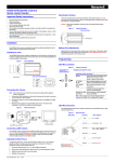
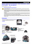
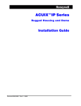
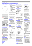
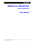
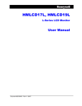
HCD544/HCD544X/HCD545X Camera
Quick Install Guide
Adjusting the Back Focus
Document 800-03503 — Rev C — 03/09
To adjust the back focus, aim the camera towards a darker area, or use a Neutral
Density lens filter. For best results, there should be a minimum of 15 ft (4.5 m)
between the camera and the target focal area.
Important Safety Instructions
•
•
•
•
•
•
•
•
•
Read and keep these instructions.
Heed all warnings.
Follow all instructions.
Do not use this apparatus near water.
Clean only with dry cloth.
Do not block any ventilation openings. Install in accordance with the manufacturer’s
instructions.
Do not install near any heat sources such as radiators, heat registers, stoves, or other
apparatus (including amplifiers) that produce heat.
Use only with the bracket or mounting system specified by the manufacturer, or sold
with the apparatus.
Refer all servicing to qualified service personnel.
1.
Loosen the setscrews (see Figure 1) with a Phillips screwdriver.
2.
Set the Zoom lens adjustment to Wide and the Focus lens adjustment to Near.
3.
Adjust the back focus ring to focus the picture.
4.
Retighten the setscrews.
Mounting the Camera
There are mounting points on the top and bottom of the camera (see Figure 3) to
mount the camera on a bracket or tripod. Use standard sized mounting bolts to install
the camera to a mounting bracket.
Caution Follow local installation codes for proper mounting bracket support
capability.
Figure 3
Installation
Camera Mounting.
Top view shown
The HCD544 Series camera is designed for general surveillance applications and is
ideally suited for low-light indoor environments.
Mounting point
Installing the Lens
The HCD544 Series camera is factory configured for a CS-mount lens. Screw the lens
(customer supplied) into the front of the camera body. An IR corrected Day/Night lens
is recommended for this camera.
Figure 1
Making Final Adjustments
Adjust the focus in your field of view until you see a clear image. If necessary, adjust
the brightness using the OSD menu controls (see LENS DC/BRIGHTNESS or AGC).
Confirm the exposure on the monitor screen.
Lens Installation
Programming
DC Lens Pin Definitions
Setscrews (x2)
Pin
Function
1
CTRL -
2
CTRL +
3
DRV +
4
DRV -
OSD Menu Controls
Figure 4
3 4
1 2
Camera OSD control
(4 position plus
center press (ENTER)
Camera Controller
Navigating through the menus
Press this control To do this …
Connecting the Camera
Note Check the power source from the external power supply before applying
power to the camera.
1.
Connect the VIDEO connector on the rear of the camera to the video-in connector
on your monitor or video recorder.
2.
HCD544/HCD544X models: Connect the camera to a power supply appropriate
for your installation (12 VDC or 24 VAC).
ENTER
Press and hold two seconds to enter
SETUP menu. Press to enter a
screen or select a menu option.
UP, DOWN
(!, ")
Move vertically between menus and
options. Increase/decrease a value.
LEFT, RIGHT
(#, $)
Move horizontally between menus
and options.
..
Indicates submenus. Select the
menu, then press ENTER.
Plug the power supply into an appropriate power source.
3.
HCD545X model: Connect the power cord to the power cord socket.
RETURN (on OSD Exit the submenu. Select RETURN,
submenus)
then press ENTER.
Plug the power cord plug into an electrical outlet of AC230V, 50 Hz. Accepted
voltage range is 207 VAC~253 VAC.
Note Menu display turns off automatically after five minutes of
no activity. Your changes will be saved.
The power LED illuminates to show that the camera is receiving power.
Figure 2
Video Connections
OSD Menu Structure
HCD544/HCD544X
Power LED
The HCD544 Series camera menu system consists of one main SETUP menu for easy
camera programming.
Figure 5
Menu Structure
Main Menu
LAMP terminal
GND terminal
Submenu
LENS
Menu Options
DC .., MANUAL
AC24V/DC12V terminal block
HCD545X
Power LED
230 VAC
power supply
GND terminal
LAMP terminal
1
2
3
4
5
6
7
<<SETUP MENU>>
LENS
DC
SHUTTER
MANUAL ..
WHITE BAL.
AWC ..
BACKLIGHT
ON
AGC
30dB
SPECIAL ..
EXIT MENU ..
Connecting LAMP Contact
The HCD544 camera is equipped with LAMP and GND external contact terminals (see
Figure 2). When the LAMP terminal is connected to the GND terminal, the camera is
forced into night mode (see DAY&NIGHT). It stays in night mode until the LAMP
terminal is disconnected from the GND terminal.
Document 800-03503 – Rev C – 03/09
SHUTTER
FLK, MANUAL .., ESC
WHITE BAL
ATW .., AWC (PUSH/LOCK), AWC
AUTO ..,USER .., MANUAL ..
BACKLIGHT
ON, OFF
AGC
See SETUP Menu Functions
for a description of the
submenus and menu options.
SPECIAL ..
18 dB~30 dB, OFF
See SPECIAL Menu.
SETUP Menu Functions
1
Menu Item
2
Menu Item
Description
LENS
Selects lens type
DC = Automatic Iris lens. Press ENTER with DC selected to adjust
the brightness level.
MANUAL = Fixed lens
2
SHUTTER
3
WHITE BAL.
Controls color on the screen. Press ENTER with ATW selected to
(White Balance) change the mode.
ATW = Select Auto Tracking White Balance when the color
temperature is 2500°K-8000°K (for example when under a
fluorescent light, or outdoors).
AWC PUSH = Automatically adjust the white balance to your
specific environment. When selected, the white balance is locked.
AWC AUTO = A faster AWB mode with a wider operating range.
USER = Adjust the red or blue gain, from 0~255.
MANUAL = Increase or decrease the red or blue gain on screen.
4
BACKLIGHT
5
AGC
Adjusts value of AGC gain
(Automatic Gain Increase the gain level (18 dB~30 dB) in 2 dB increments to
Control)
brighten the picture in low light conditions. Noise/distortion may
develop.
OFF = DAY&NIGHT mode must be OFF to turn AGC OFF.
6
SPECIAL..
Opens the SPECIAL menu (see SPECIAL Menu)
7
EXIT MENU
Exits the SETUP menu and returns to video monitoring
SAVE AND EXIT = Exits the SETUP menu, saving your changes,
and returns to video monitoring. If the camera times out after five
minutes of inactivity, your changes are not saved.
EXIT = Exits the SETUP menu without saving your changes.
RETURN = Returns to the SETUP menu.
SPECIAL Menu
1.
On the SETUP menu, press the UP or DOWN menu control and then select
SPECIAL.
2.
Press ENTER to access the SPECIAL menu.
Figure 6
➝
➝
<<SPECIAL MENU>>
CAMERA ID
DAY&NIGHT
AUTO ..
PRIVACY
ON ..
MIRROR
OFF
SHARPNESS
11
FACTORY DEFAULT YES
SW VERSION
0.16
RETURN
ON, OFF
DAY&NIGHT
AUTO .., ON, OFF
PRIVACY
MIRROR
FACTORYDEFAULT
ON .., OFF
0~15
NO, YES
SPECIAL Menu Functions
Menu Item
Description
CAMERA ID
Sets a camera ID to be displayed on the monitor. To add a camera
ID (maximum 10 characters, including spaces):
POSITION
R.BOT
ABCDEFGHIJKLMNOPQRST
UVWXYZabcdefghijklmn
opqrstuvwxyz12345678
9!?#$&<>*.:;/+–=~"
ID:
RETURN
PRIVACY
Masks an area of the screen from video monitoring
<<PRIVACY>>
CONTROL
ON
H START
100
H END
130
V START
50
V END
80
RETURN
Menu Item Description
CONTROL ON = Hide an area of the scene from
viewing.
H START
Set a horizontal start position (0~187).
H END
Set a horizontal end position (0~187).
V START
Set a vertical start position (0~122).
V END
Set a vertical end position (0~122).
4
MIRROR
Produces a horizontal mirror image on screen
5
SHARPNESS
Sharpens the image on screen (image level 0~15). Excessive
sharpening may cause picture noise.
6
FACTORYDEFAULT
Restores all factory default settings
7
SW VERSION
Displays the current firmware version
8
RETURN
Returns to the main SETUP menu
ON .., OFF
See SPECIAL Menu Functions
for a description of the
submenus and menu options.
<<CAMERA ID>>
3
AUTO
5sec
5
8
B/W
Menu Options
CAMERA ID
SHARPNESS
1
MODE
DETECT TIME
D
N LEVEL
N
D LEVEL
NIGHT COLOR
RETURN
Menu Item Description
MODE
AUTO = Depending on the light level, the
camera automatically switches to night
mode.
ON = The camera is forced into night mode
at all times.
OFF = The camera never switches to night
mode.
DETECT
Sets the time (5~60, in 5-second increments)
TIME
before the camera switches to day or night
mode after detecting a switching threshold.
The light detection level (1~12) at which the
D➝ N
LEVEL
camera switches to night mode.
N➝D
The light detection level (4~15) at which the
LEVEL
camera switches to day mode.
Set MODE to AUTO and D➝N LEVEL at least
3 less than N➝D LEVEL.
NIGHT
Set the color mode in night mode.
COLOR
B/W = Black/white (no color burst)
COLOR = Color
Set MODE to AUTO or ON.
SPECIAL Menu
Submenu
1
2
3
4
5
6
7
8
DAY&NIGHT
<<DAY&NIGHT>>
Adjusts shutter settings
FLK = Flickerless mode reduces on-screen flickering.
MANUAL = Adjust the shutter speed from 1/60-1/100,000 of a
second (NTSC), or 1/50-1/100,000 (PAL).
ESC = Electronic Shutter Control. Press ENTER to adjust the
brightness level. Not available with DC lens.
Controls the light level to overcome severe backlighting conditions
Description
UP, DOWN, LEFT, or RIGHT menu control = Select a
character, then press ENTER to accept it. The character is
saved and the cursor moves to the next position.
LEFT or RIGHT menu control = Go back or forward in the
name or number to make changes.
POSITION = Position the camera ID on the screen. Press
(ENTER) SET to confirm the position.
ID = Sets a camera ID to be displayed.
Select RETURN when you are finished.
Honeywell Systems Group
(Head Office)
2700 Blankenbaker Pkwy, Suite 150
Louisville, KY 40299, USA
www.honeywellvideo.com
℡ +1.800.796.2288
Honeywell Security UK
Aston Fields Road
Whitehouse Ind Est
Runcorn, Cheshire, WA7 3DL, UK
www.honeywell.com/security/uk
℡ +08448.000.235
Honeywell Security Australia Pty Ltd.
Units 4+5, Riverside Center
24-28 River Road West
Parramatta, NSW 2150, Australia
www.honeywellsecurity.com.au
℡ +61.2.8837.9300
Honeywell Video Systems
Northern Europe
Netwerk 121
1446 WV Purmerend
The Netherlands
www.honeywell.com/security/nl
℡ +31.299.410.200
Honeywell Security Asia Pacific
33/F Tower A, City Center, 100 Zun Yi Road
Shanghai 200051, China
www.asia.security.honeywell.com
℡ +86 21.5257.4568
Honeywell Security Asia
Flat A, 16/F, CDW Building
388 Castle Peak Road
Tsuen Wan, N.T., Hong Kong
www.asia.security.honeywell.com
℡ +852.2405.2323
Honeywell Security Deutschland
Johannes-Mauthe-Straße 14
D-72458 Albstadt, Germany
www.honeywell.com/security/de
℡ +49.74 31.8 01.0
Honeywell Security France
Parc Gutenberg, 8
Voie La Cardon
91120, Palaiseau, France
www.honeywell.com/security/fr
℡ +33.01.64.53.80.40
Honeywell Security South Africa
Honeywell House, Bekker Street
Truer Close, Waterfall Park
Midrand 1685, South Africa
www.honeywell.com/security/za
℡ +27.11.695.8000
Honeywell Security Italia SpA
Via della Resistenza 53/59
20090 Buccinasco, Milan, Italy
www.honeywell.com/security/it
℡ +39.02.4888.051
Honeywell Security Middle East
Post Office Box 18530
LOB Building 08, Office 199
Jebel Ali, Dubai United Arab Emirates
www.honeywell.com/security/me
℡ +971.04.881.5506
Honeywell Security España
Mijancas 1. 3a planta
P.Ind. Las Mercedes
28022 Madrid, Spain
www.honeywell.com/security/es
℡ +34.902.667.800
www.honeywellvideo.com
+1.800.796.CCTV (North America only)
[email protected]
Document 800-03503 – Rev C – 03/09
© 2009 Honeywell International Inc. All rights reserved. No part of this publication may be reproduced by any means without written permission from Honeywell. The information in this publication is believed to be accurate in all respects.
However, Honeywell cannot assume responsibility for any consequences resulting from the use thereof. The information contained herein is subject to change without notice. Revisions or new editions to this publication may be issued to
incorporate such changes.