1
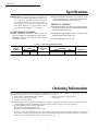
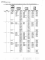
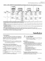
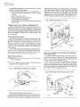
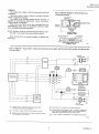
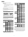
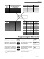
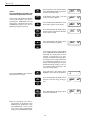
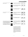
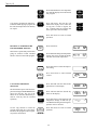
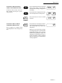
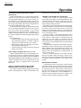
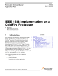
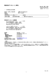
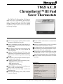
T8621A,C,D
Chronotherm™ III Fuel
Saver Thermostats
The T8621A,C,D Chronotherm III Programmable Fuel Saver Thermostats provide automatic control of single or multistage heating/
cooling systems and offer users the highest
standard of comfort and convenience available
with energy savings.
■ Full seven-day program capability; different sched-
■ Models available with automatic or manual heat/
ules may be selected for every day.
Can be programmed in hand (with batteries installed) or on wall to provide up to four temperature
settings per day.
Large digital clock (liquid crystal display) indicates continuous time, day, current period and
room temperature.
Adaptive Intelligent Recovery™ brings room
temperature to programmed temperature at programmed time, maximizing comfort and energy
savings.
Temperature control program maintains temperature within 1° F of setpoint.
Temporary program override available by using—
—WARMER and COOLER keys
—SKIP next period key
—CHANGE to last period key
HOLD TEMP key provided for indefinite program override (vacation/holiday).
Installer self-test and time delay override save
installation time.
SYSTEM light-emitting diode (LED) indicates
system is energized.
cool changeover.
Batteries included provide power to maintain
clock and memory during power failures.
Switching subbase with wiring terminals included.
Powered directly from control transformer, requiring an extra (24V) wire to thermostat.
Fan operation switch included on back of SUPER
TRADELINE models to select either independent or direct thermostat control of fan in heating.
Models available with separate sensor for remote
mounting.
■
■
■
■
■
■
■
■
■
■
■
■
■
CONTENTS
Specifications ............................................... 2
Ordering Information ................................... 2
Selection/Application ................................... 5
Installation ................................................... 7
Checkout ..................................................... 17
Programming the Thermostat .................... 19
Operating the Thermostat .......................... 25
Operation ................................................... 28
Troubleshooting ......................................... 29
Glossary ..................................................... 30
Table of Contents ....................................... 31
C. H. • Rev. 18-92 • ©Honeywell Inc. 1992 • Form Number 68-0058—1
68-0058—1
T8621A,C,D
SPECIFICATIONS • ORDERING INFORMATION
Specifications
IMPORTANT: The specifications given in this publication do not include normal manufacturing tolerances. Therefore, this unit may not exactly match
the listed specifications. Also, this product is
tested under closely controlled conditions, and
some minor differences in performance can be
expected if those conditions are changed.
SUPER TRADELINE FEATURE: Fan operation switch
on back of thermostat to select either independent or
direct thermostat control of fan in heating.
TRADELINE MODELS
TRADELINE models, see Table 2, are selected and packaged to provide ease of stocking and handling and also
maximum replacement value.
SUPER TRADELINE MODEL
LIGHT-EMITTING DIODE (LED): SYSTEM LED
lights during thermostat ON cycle.
SUPER TRADELINE controls, see Table 1, offer features not available on TRADELINE models and are
designed to replace a wide range of Honeywell and
competitive controls.
VOLTAGE RATING: 15 to 30 Vac.
TABLE 1—SUPER TRADELINE MODEL.
Thermostat
Model
Number
T8621D
Stages
Heat
Cool
2
2
Changeover
Type
Manual
Switching
System
Fan
HEAT-OFF-COOL
ON-AUTO
Application
Multistage
Ordering Information
When purchasing replacement and modernization products from your TRADELINE® wholesaler or distributor, refer to the
TRADELINE Catalog or price sheets for complete ordering number, or specify—
1. Model number; SUPER TRADELINE, if desired.
4. Remote temperature sensing, if desired.
2. Number of heat and cool stages desired.
5. Application.
3. System, fan switching desired.
If you have additional questions, need further information or would like to comment on our products or services, please write or phone:
1. Your local Honeywell Home and Building Control Sales Office (check white pages of your phone directory).
2. Home and Building Control Customer Satisfaction
Honeywell Inc., 1885 Douglas Drive North
Minneapolis, Minnesota 55422-4386 (612) 951-1000
In Canada—Honeywell Limited/Honeywell Limitee, 740 Ellesmere Road, Scarborough, Ontario M1P 2V9. International
Sales and Service offices in all principal cities of the world. Manufacturing in Australia, Canada, Finland, France, Germany,
Japan, Mexico, Netherlands, Spain, Taiwan, United Kingdom, U.S.A.
2
T8621A,C,D
SPECIFICATIONS
TABLE 2—TRADELINE MODELS.
Thermostat
Model
Number
T8621A*
Stages
Heat
Cool
1
1
Changeover
Type
Auto
T8621C
2
1
Auto
T8621D*
2
2
Auto
Switching
System
Fan
HEAT-AUTOON-AUTO
COOL-OFF
HEAT-AUTOON-AUTO
COOL-OFF
HEAT-AUTOON-AUTO
COOL-OFF
Application
Single stage
Multistage
Multistage
*Model available with separate sensor for remote mounting.
CURRENT RATING: 1.6A maximum total per stage.
6 cph; adjustable for other systems.
Cooling: Factory-set at 3 cph (not field adjustable);
minimum off-time of five minutes.
OPERATING HUMIDITY RANGE: 5 to 90 percent
relative humidity, noncondensing.
FINISH: Beige matte with decorative brushed metal faceplate.
OPERATING AMBIENT TEMPERATURE RANGE:
40° F to 110° F [4° C to 43° C].
DIMENSIONS: Thermostat (mounted on subbase)—7
in. [178 mm] long, 5-5/16 in. [135 mm] high, 1-3/
4 in. [44 mm] deep. See Fig. 1 for subbase dimensions and Fig. 2 for sensor dimensions.
SETPOINT RANGE: 45° F to 88° F [7° C to 31° C].
CALIBRATION: Self-calibrating thermostat and thermometer to ±1° F.
TYPICAL KEYPAD: See Fig. 3.
SHIPPING TEMPERATURE: -20° F to +120° F [-29° C to
+49° C].
ACCESSORIES:
TG586A Locking Cover.
TG512 Versaguard Universal Thermostat Guard.
CYCLES PER HOUR ADJUSTMENT:
Heating: First stage of 2-stage heat models—fixed at
3 cph. Second stage of 2-stage heat models or
heat stage of single-stage heat models—factoryset
at
REPLACEMENT PARTS:
202905AA Remote Temperature Sensor Assembly.
Includes sensor, screws, anchors and instructions. See
Fig. 2 for dimensions.
Fig. 1—T8621 Subbase mounting dimensions in in. [mm].
31
32
[50]
1
13
1
16
[46]
3
4 32
[104]
5
16
[135]
5
3
4
M5181A
5
[83]
16
3
[121]
4
7 [179]
3
68-0058—1
T8621A,C,D
SPECIFICATIONS • SELECTION/APPLICATION
Fig. 2—202905AA Remote Temperature Sensor dimensions in in. [mm].
FRONT
BACK
SIDE
2
31
32
[50]
1
[51]
1
3
4 32
31 [50]
32
19
[8]
64
41
64 [16]
[104]
9 [4]
64
1 3 [35]
8
1
DIA.
2
[13]
1 [25]
M5244
Fig. 3—Typical thermostat keypad.
AM
SYSTEM
ROOM
WED
HEAT ON
MIDDAY
TEMPERATURE
PRESENT
SETTING
RUN
PROGRAM
TIME
SET
PRESENT
DAY/TIME
DAY
PERIOD
COPY
FROM
HOLD
TEMP
SET
HEAT/COOL
CANCEL
PERIOD
COPY
TO
AHEAD
WARMER
BACK
COOLER
SKIP
NEXT
PERIOD
CHANGE
TO LAST
PERIOD
FAN
HEAT
OFF
COOL
ON
AUTO
M5360
4
T8621A,C,D
INSTALLATION
Fig. 9—T8621C 2-stage heat/1-stage cool thermostat with HEAT-AUTO-COOL-OFF system and AUTO-ON
fan switching.
HEATING
TRANSFORMER
R
4
2
HIGH
LIMIT
1
L1
(HOT)
L2
3
POWER
SUPPLY
C
HIGH
LIMIT
HEAT RELAY 1
HEAT 1
W1
HEAT RELAY 2
HEAT 2
W2
SYSTEM
SWITCH
HEAT
THERMOSTAT
LOGIC CIRCUIT
AUTO
COOL
OFF
COOLING
CONTACTOR
COOL
Y1
FAN
SWITCH
SUBBASE
LOGIC/
CONTROL
CIRCUIT
FAN RELAY
AUTO
G
ON
2
L1
(HOT)
RC
L2
COOLING
TRANSFORMER
1
POWER SUPPLY. PROVIDE DISCONNECT MEANS AND OVERLOAD
PROTECTION AS REQUIRED.
3
2
FOR SINGLE TRANSFORMER SYSTEM JUMPER R AND RC.
4
1
NOMINAL 24 Vac POWER MUST BE PRESENT BETWEEN R AND C FOR
THERMOSTAT OPERATION.
DENOTES THERMOSTAT TO SUBBASE INTERCONNECTION.
M5233
10
T8621A,C,D
INSTALLATION
Fig. 10—T8621D 2-stage heat/2-stage cool thermostat with HEAT-AUTO-COOL-OFF system and AUTO-ON
fan switching.
HEATING
TRANSFORMER
1
L1
(HOT)
R
6
2
HIGH
LIMIT
L2
3
POWER
SUPPLY
C
HIGH
LIMIT
HEAT 1
HEAT RELAY 1
W1
HEAT 2
HEAT RELAY 2
W2
SYSTEM
SWITCH
A
A
S1
S1
AUTO
S2
S2
COOL
S3
HEAT
THERMOSTAT
LOGIC CIRCUIT
4
S3
5
202905 REMOTE
SENSOR
OFF
COOL 2
Y2
COOLING
CONTACTOR 2
COOL 1
Y1
FAN
SWITCH
SUBBASE
LOGIC/
CONTROL
CIRCUIT
COOLING
CONTACTOR 1
AUTO
G
ON
FAN RELAY
2
L1
(HOT)
RC
L2
1
COOLING
TRANSFORMER
1
POWER SUPPLY. PROVIDE DISCONNECT MEANS AND OVERLOAD
PROTECTION AS REQUIRED.
2
FOR SINGLE TRANSFORMER SYSTEM JUMPER R AND RC.
3 NOMINAL 24 Vac POWER MUST BE PRESENT BETWEEN R AND C FOR
THERMOSTAT OPERATION.
4
APPLICABLE ONLY ON T8621D MODEL WITH REMOTE SENSOR.
5
RECOMMENDED INTERCONNECT CABLE: 18-GAUGE THERMOSTAT
CABLE, 200 ft. [61 m] MAXIMUM LENGTH. ROUTE INTERCONNECT
CABLE AWAY FROM SOURCES OF ELECTRICAL NOISE.
6
DENOTES THERMOSTAT TO SUBBASE INTERCONNECTION.
M1031E
11
68-0058—1
T8621A,C,D
INSTALLATION
Fig. 11—T8621D 2-stage heat/2-stage cool thermostat with HEAT-OFF-COOL system and AUTO-ON fan
switching; auto fan on heat and cool; convertible to auto fan on cool only.
L1
(HOT)
L2
1
HEATING
TRANSFORMER
R
5
4
POWER
SUPPLY
C
HIGH
LIMIT
FAN
OPERATION
SWITCH
HIGH
LIMIT
W1
3
ELECTRIC
NON-ELECTRIC
2
STAGE 1
HEAT RELAY
HEAT 1
W2
SYSTEM
SWITCH
HEAT 2
STAGE 2
HEAT RELAY
HEAT
B
THERMOSTAT
LOGIC CIRCUIT
OFF
HEATING DAMPER OR
CHANGEOVER RELAY
COOL
COOLING DAMPER OR
CHANGEOVER RELAY
O
STAGE 2
COOLING RELAY
Y2
COOL 1
COOL 2
STAGE 1
COOLING RELAY
SUBBASE
LOGIC/
CONTROL
CIRCUIT
Y1
FAN
SWITCH
AUTO
FAN RELAY
G
ON
3
RC
COOLING
TRANSFORMER
1
L1
L2
(HOT)
1
POWER SUPPLY. PROVIDE DISCONNECT MEANS AND OVERLOAD
PROTECTION AS REQUIRED.
2
FOR GAS OR OIL APPLICATIONS OR ELECTRIC HEAT APPLICATIONS
WHERE THE FAN OPERATION IS CONTROLLED INDEPENDENTLY OF
THE THERMOSTAT (AUTO FAN OPERATES WITH Y1 ONLY), TWO
TRANSFORMERS MAY BE USED. SET SWITCH TO NON-ELECTRIC
POSITION.
3
FOR ELECTRIC HEAT APPLICATIONS (AUTO FAN OPERATES WITH W1
AND Y1). USE ONLY ONE TRANSFORMER; JUMPER R AND RC. SET
SWITCH TO ELECTRIC POSITION.
4
NOMINAL 24 VAC POWER MUST BE PRESENT BETWEEN R AND C FOR
THERMOSTAT OPERATION.
5
DENOTES THERMOSTAT TO SUBBASE INTERCONNECTION.
M1016C
12
T8621A,C,D
INSTALLATION
Fig. 12—T8621C,D single stage heat pump with heating changeover. HEAT-AUTO-COOL-OFF system and
AUTO-ON fan switching.
L1
(HOT)
L2
1
SYSTEM
TRANSFORMER
5
R
HIGH
LIMIT
POWER
SUPPLY
C
HIGH
LIMIT
HEATING
CHANGEOVER
H1
W1
SYSTEM
SWITCH
COMPRESSOR
CONTACTOR
H2
HEAT
W2
THERMOSTAT
LOGIC CIRCUIT
AUTO
COOL
OFF
C2
4
Y2
C1
Y1
FAN
SWITCH
AUTO
SUBBASE
LOGIC/
CONTROL
CIRCUIT
FAN RELAY
G
ON
AA
A
A
A
AA
RC
S1
S1
S2
S2
S3
3
1
POWER SUPPLY. PROVIDE DISCONNECT MEANS AND OVERLOAD
PROTECTION AS REQUIRED.
2
APPLICABLE ONLY ON T8621 MODEL WITH REMOTE SENSOR.
4
5
3
2
S3
202905 REMOTE
SENSOR
T8621D ONLY.
DENOTES THERMOSTAT TO SUBBASE CONNECTIONS.
NOTE: SET CYCLE RATE TO HOT WATER SETTING (3 cph).
THERMOSTAT DOES NOT PROVIDE MINIMUM OFF TIME IN
HEATING.
RECOMMENDED INTERCONNECT CABLE: 18-GAUGE THERMOSTAT
CABLE, 200 ft. [61 m] MAXIMUM LENGTH. ROUTE INTERCONNECT
CABLE AWAY FROM SOURCES OF ELECTRICAL NOISE.
M1547C
13
68-0058—1
T8621A,C,D
INSTALLATION
Fig. 13—T8621C,D single stage heat pump with cooling changeover. HEAT-AUTO-COOL-OFF system and
AUTO-ON fan switching.
L1
(HOT)
L2
1
6
SYSTEM
TRANSFORMER
R
POWER
SUPPLY
HIGH
LIMIT
C
HIGH
LIMIT
H1
K
RELAY K
W1
SYSTEM
SWITCH
COOLING
CHANGEOVER
H2
HEAT
THERMOSTAT
LOGIC CIRCUIT
W2
AUTO
COMPRESSOR
CONTACTOR
COOL
OFF
C2
5
Y2
C1
Y1
FAN
SWITCH
AUTO
SUBBASE
LOGIC/
CONTROL
CIRCUIT
FAN RELAY
G
ON
RC
A
A
S1
S1
S2
S2
S3
4
1
POWER SUPPLY. PROVIDE DISCONNECT MEANS AND OVERLOAD
PROTECTION AS REQUIRED.
2
ADD RELAY (SPDT) TO ACCOMMODATE COOLING CHANGEOVER.
3
APPLICABLE ONLY ON T8621D MODELS WITH REMOTE SENSOR.
3
S3
202905 REMOTE
SENSOR
4
RECOMMENDED INTERCONNECT CABLE: 18-GAUGE THERMOSTAT CABLE,
200 ft. [61 m] MAXIMUM LENGTH. ROUTE INTERCONNECT CABLE AWAY
FROM SOURCES OF ELECTRICAL NOISE.
5
T8621D ONLY.
6
DENOTES THERMOSTAT TO SUBBASE INTERCONNECTION.
NOTE: SET CYCLE RATE TO HOT WATER SETTING (3 cph). THERMOSTAT
DOES NOT PROVIDE MINIMUM OFF TIME IN HEATING.
M1548C
14
T8621A,C,D
INSTALLATION
Fig. 14—T8621D single stage heat pump. HEAT-OFF-COOL system and AUTO-ON fan switching.
L1
(HOT)
L2
1
SYSTEM
TRANSFORMER
4
R
3
POWER
SUPPLY
HIGH
LIMIT
C
2
HIGH
LIMIT
FAN
OPERATION
SWITCH
W1
ELECTRIC
HEAT 1
NON-ELECTRIC
W2
HEAT 2
SYSTEM
SWITCH
HEAT
THERMOSTAT
LOGIC CIRCUIT
HEATING
CHANGEOVER
RELAY
B
OFF
COOL
COOLING
CHANGEOVER
RELAY
O
Y2
COOL 1
COOL 2
COMPRESSOR
CONTACTOR
SUBBASE
LOGIC/
CONTROL
CIRCUIT
Y1
FAN
SWITCH
FAN RELAY
AUTO
G
ON
RC
1
POWER SUPPLY. PROVIDE DISCONNECT MEANS AND
OVERLOAD PROTECTION AS REQUIRED.
3
2
FAN OPERATION SWITCH MAY BE IN EITHER POSITION.
4
NOMINAL 24 VAC POWER MUST BE PRESENT BETWEEN R AND C FOR
THERMOSTAT OPERATION.
DENOTES THERMOSTAT TO SUBBASE INTERCONNECTION.
NOTE: THERMOSTAT DOES NOT PROVIDE MINIMUM OFF TIME IN
HEATING.
M1546A
cycle rate.
Refer to Figs. 8-14 for typical hookups of subbase and
thermostat.
The room air temperature will normally vary slightly
from the comfort temperature setting with the cycling of
the fur-nace or air conditioner.
The cooling cycle rate is factory-set and cannot be
adjusted. The heating cycle rate can be adjusted by turning
one or both cycle rate adjustment screws located on the
back of the thermostat. In multistage heat systems, the
cycle rate adjustment applies to the highest stage of heat
only. Screws should be backed out about one-half to one
turn, or be turned in until tight. See Fig. 15.
ADJUSTING CYCLE RATE
To customize the thermostat cycling performance to
various types of heating equipment, cycle rate adjustment
screws are provided on the back of the thermostat to
provide optimum room temperature control.
NOTE: Most applications will not require a change in
15
68-0058—1
T8621A,C,D
INSTALLATION • CHECKOUT
Fig. 17—Mounting thermostat on subbase.
A.
B.
SYSTEM
PM
MON
MORNIMG
ROOM
HEAT ON
FAN
AUTO
ON AUTO
COOL OFF
HEAT AUTO
C.
SYSTEM
PM
ROOM
HEAT ON
MON
MORNIMG
TEMPERATURE
PRESENT
SETTING
RUN
PROGRAM
TIME
SET
PRESENT
DAY/TIME
DAY
PERIOD
COPY
FROM
HOLD
TEMP
SET
HEAT/COOL
CANCEL
PERIOD
COPY
TO
AHEAD
WARMER
BACK
COOLER
SKIP
NEXT
PERIOD
CHANGE
TO LAST
PERIOD
M 843
Checkout
NOTE: When cooling setting is changed, thermostat will
wait up to five minutes before turning on the cooling
equipment. This delay is to protect the compressor.
HEATING
Move the system switch to HEAT and the fan switch to
AUTO. Press WARMER key until the setting is about 10°
F [6° C] above room temperature. Heating should start
(both stages if multistage), and the fan should run (may be
a short delay on forced air systems). Press cooler key until
the setting is about 10° F [6° C] below room temperature.
The heating equipment should shut off, followed by the
fan.
Move the system switch to COOL and the fan
switch to AUTO. Press COOLER key until the setting
is about 10° F [6° C] Below room temperature. The
cooling equipment and fan should start (both stages if
multistage). Press WARMER key until the setting is
about 10° F [6° C] above room temperature. The
cooling equipment and fan should stop.
NOTE: On an AUTO changeover thermostat, the cooling
temperature must be set at least 3° F [2° C] above the
heating temperature, or display will flash.
NOTE: On an AUTO changeover thermostat, the heating
temperature must be set at least 3° F [2° C] below the
cooling temperature, or display will flash.
COOLING
!
FAN
Move the system switch to OFF, and the fan switch to
ON. The fan should run continuously. When the fan switch
is in the AUTO position, fan operates directly with the
thermostat call for cooling and also with the thermostat
call for heating.
CAUTION
Do not operate cooling if outdoor temperature is
below 50° F [10° C]. Refer to manufacturer’s
recommendations.
17
68-0058—1
T8621A,C,D
CHECKOUT
INSTALLER SELF-TEST (OPTIONAL)
IMPORTANT:
1. Thermostat must have ac power to perform selftest. Relays will not toggle, codes will not be
present and thermostat will not manually exit
self-test without ac power.
2. Five-minute time delay on cooling does not function
during self-test.
System
Switch
Position
OFF
Press
This
Key
WARMER
02
Blank
05
Blank
04
Blank
01
Blank
00
Blank
12
See note A .
08
Blank
13
09
Microprocessor mask
no. and revision no.
Blank
SET
PRESENT
DAY/TIME
14
Blank
SET
PRESENT
DAY/TIME
14
SET
PRESENT
DAY/TIME
14
SET
PRESENT
DAY/TIME
14
1st stage heating and
SYSTEM LED on.
2nd stage heating
also on.
2nd stage heating off.
COOLER
Perform the following test as a check of all thermostat
functions. If thermostat does not respond as indicated,
thermostat must be replaced.
1. Press AHEAD and BACK keys at the same time.
While holding keys down, all segments of the display
should be on (see Fig. 18).
AHEAD
BACK
COPY
FROM
COPY
TO
Fig. 18—All segments on display.
AM
PM
REPL
(CHECK
EACH
POSITION)
OFF
SET
PT
BAT
ROOM
SUN MON TUE WED THU FRI SAT TEMPORARY OUTDOOR
MORNING MIDDAY EVENING NIGHT COOL ON HEAT ON
CHANGE
TO LAST
PERIOD
SKIP
NEXT
PERIOD
SET
PRESENT
SETTING
COOL or
AUTO
(with fan
in AUTO)
PRESENT
SETTING
PRESENT
SETTING
PRESENT
SETTING
PRESENT
SETTING
HEAT or
AUTO
1
Look For This Response
Key
Down
Key Released
03
Blank
07
Blank
15
Blank
15
1st stage cooling,
fan and SYSTEM
LED on.
2nd stage cooling
also on.
2nd stage cooling
off.
1st stage cooling,
fan and SYSTEM
LED off.
15
15
15
CANCEL
PERIOD
HEAT/COOL
2. Set the system switch to OFF. Press and release
AHEAD and BACK and PRESENT SETTING keys at the
same time to enter self-test.
3. Press each key as listed below, and look for responses listed as key is held down and released.
Press
This
Key
PERIOD
DAY
M 525A
System
Switch
Position
OFF
Look For This Response
Key
Down
Key Released
06
Blank
1st stage heating and
SYSTEM LED off.
NOTE: If single-stage heating system, press key twice
instead of 4 times; once to turn heating and SYSTEM
LED on, second time to turn off.
SET
PRESENT
DAY/TIME
OFF
HOLD
TEMP
RUN
PROGRAM
14
10
Blank
11
Normal operating
display.
END SELF-TEST
1
A
NOTE: If single-stage cooling system, press key twice
instead of 4 times; once to turn cooling, fan and SYSTEM LED on, second time to turn off.
18
For electric heat fan operation—The fan will operate
with the heating system when fan switch is in AUTO.
HEAT displayed when system switch is in HEAT,
COOL when in COOL, HEAT and COOL when in
AUTO, neither when in OFF. Also, a four-digit code
is displayed, with each digit explained below.
T8621A,C,D
CHECKOUT • PROGRAMMING THE THERMOSTAT
First
Digit
0
1
2
3
Second
Digit
0
1
2
3
4
5
6
Cycle Rate Setting
(cph at 50% on time for stage
1 on 1-heat models, stage
2 on 2-heat models)
1
3
9
6
Third
Digit
0
1
3
4
5
Stages of
Heat
2
2
1
1
0
1
2
Cool
1
2
1
2
2
0
0
Manual or Auto
Changeover
Manual
Auto
Auto
Manual
Auto
Fourth
Digit
0
Degrees
F
Clock
(hrs)
12
1
F
24
2
3
4
F
F
C
12
24
12
5
C
24
6
7
C
C
12
24
System Switch
Position
HEAT or OFF
HEAT or OFF
AUTO
COOL
COOL
System Switch
Position
COOL, AUTO
or OFF
COOL, AUTO
or OFF
HEAT
HEAT
COOL, AUTO
or OFF
COOL, AUTO
or OFF
HEAT
HEAT
Programming the Thermostat
STEP 1
ENTER THE DAY AND TIME
This thermostat can be programmed
either on wall or in hand. See page 8 to
find out how to remove the thermostat
from the subbase.
SET
PRESENT
DAY/TIME
Press and release. The display shows
1:00 PM Mon.
DAY
Press and hold until the current day
appears in the display.
PM
MON
PM
TUE
TIME
Always press the keys with fingertip
or similar blunt tool. Sharp instruments
like a pen or pencil point can damage
the keyboard.
NOTE: Check the glossary, page 30
for definitions of unfamiliar
words.
AHEAD
Press and hold until the current time
appears in the display. Be sure AM or
PM appears as desired.
PM
TUE
BACK
This completes setting the current day
and time. Go on to Step 2.
19
68-0058—1
T8621A,C,D
PROGRAMMING THE THERMOSTAT
STEP 2
SET THE PROGRAM TIMES AND
TEMPERATURES FOR ONE DAY
Choose a day to program first. Monday
is used in the examples. Start by programming the MORNING time and
temperatures. The thermostat requires
a MORNING program every day. Set
additional programs as desired.
PERIOD
Press and release. Note that the display
shows MORNING and the preprogrammed time and temperature.
SET
If the display reads COOL, press and
release to switch to HEAT.
HEAT/COOL
DAY
AHEAD
Press and hold until MONDAY (or the
desired day) appears in the display.
Press and hold until the display shows
the time that the temperature should be
at the comfort setting.
AM
MON TUE WED THU FRI
MORNING
SET
PT
HEAT
AM
MON TUE WED THU FRI
MORNING
SET
PT
HEAT
AM
MON TUE WED THU FRI
MORNING
SET
PT
HEAT
AM
MON TUE WED THU FRI
MORNING
SET
PT
HEAT
BACK
WARMER
Press and hold until the display shows
the desired heating temperature.
AM
SET
PT
MON TUE WED THU FRI
MORNING
HEAT
MON TUE WED THU FRI
DAYTIME
MIDDAY
HEAT
COOLER
If the display flashes while holding
down TEMPERATURE WARMER or
COOLER, the setting limit has been
reached. If thermostat is an autochangeover model, the heating temperature must be at least 3 degrees below the
air conditioning temperature. For example, if the cooling setting is 75° F, the
maximum heating setting is 72° F. To
set a higher heating temperature, first
raise the cooling setting.
Program the MIDDAY time and heating temperature if desired.
PERIOD
AHEAD
Press and release. The display shows
MIDDAY, but no time or temperature.
Press and hold until the display shows
the time to start the energy saving period.
SET
PT
AM
MON TUE WED THU FRI
DAYTIME
MIDDAY
SET
PT
HEAT
BACK
AM
WARMER
Press and hold until the display shows
the desired temperature.
COOLER
NOTE: It is possible to cancel any period showing on the display except
MORNING by pushing the CANCEL PERIOD key. To move to the
next period while programming,
simply press the PERIOD key again.
20
MON TUE WED THU FRI
DAYTIME
MIDDAY
SET
PT
HEAT
T8621A,C,D
PROGRAMMING THE THERMOSTAT
Program the EVENING time and temperature, if desired.
PERIOD
AHEAD
Press and release. The display shows
EVENING but no time or temperature.
Press and hold until the display
shows the time the temperature should
be at the comfort setting.
SET
PT
MON TUE WED THU FRI
EVENING
HEAT
SET
PT
PM
MON TUE WED THU FRI
EVENING
HEAT
BACK
WARMER
Press and hold until the display shows
the desired heating temperature.
SET
PT
PM
MON TUE WED THU FRI
EVENING
HEAT
COOLER
Program the NIGHT time and temperature, if desired.
PERIOD
AHEAD
Press and release. The display shows
NIGHT and the preprogrammed time
and temperature.
Press and hold until the display shows
the time to start the energy saving period.
SET
PT
PM
MON TUE WED THU FRI
NIGHT
HEAT
SET
PT
PM
MON TUE WED THU FRI
NIGHT
HEAT
BACK
WARMER
Press and hold until the display shows
the desired heating temperature.
SET
PT
PM
MON TUE WED THU FRI
NIGHT
HEAT
COOLER
Set the cooling temperatures for all the
periods programmed.The program times
are the same for both heating and cooling. Only the cooling temperatures need
to be programmed if programming has
been completed for heating. If you
change program times for cooling, you
are also changing the times for heating.
SET
HEAT/COOL
WARMER
Press and release. The display shows
COOL, the preprogrammed cooling
temperature and the programmed start
time for NIGHT.
Press and hold until the display shows
the desired cooling temperature for
NIGHT.
SET
PT
PM
MON TUE WED THU FRI
NIGHT
COOL
SET
PT
PM
MON TUE WED THU FRI
NIGHT
COOL
COOLER
If the display blinks while holding
down TEMPERATURE WARMER or
COOLER, the setting limit has been
reached. If thermostat can switch automatically between heating and cooling,
the heating temperature must be at least
3 degrees F below the air conditioning
temperature. For example, if the heating setting is 72° F, the minimum cooling set-ting is 75° F. To set the cooling
temperature lower, first lower the heating setting.
21
68-0058—1
T8621A,C,D
PROGRAMMING THE THERMOSTAT
PERIOD
WARMER
Press and release. The display shows
the preprogrammed cooling temperature and the programmed start time for
MORNING.
Press and hold until the display shows
the desired cooling temperature for
MORNING.
AM
MON TUE WED THU FRI
MORNING
SET
PT
COOL
AM
MON TUE WED THU FRI
MORNING
SET
PT
COOL
COOLER
PERIOD
WARMER
Press and release. The display shows
the preprogrammed cooling temperature and the programmed start time
for MIDDAY.
Press and hold until the display shows
the desired cooling temperature for
MIDDAY.
AM
MON TUE WED THU FRI
DAYTIME
MIDDAY
SET
PT
COOL
AM
MON TUE WED THU FRI
DAYTIME
MIDDAY
SET
PT
COOL
COOLER
PERIOD
WARMER
COOLER
Press and release. The display shows
the preprogrammed cooling temperature and the programmed start time for
EVENING.
Press and hold until the display shows
the desired cooling temperature for
EVENING.
SET
PT
PM
MON TUE WED THU FRI
EVENING
COOL
SET
PT
PM
MON TUE WED THU FRI
EVENING
COOL
This completes the program schedule
for one day. Go to Step 3 to copy this
program to additional days.
STEP 3
COPY THE PROGRAM TO THE
DESIRED DAYS
It is possible to copy the program for
one day to any other day or combination
of days. The new program will replace
any program already set in the day selected.
PERIOD
DAY
If necessary, press and release to enter
the programming mode.
Press and hold until the day containing
the program to be copied shows in the
display.
SUN MON TUE WED THU FRI SAT
COPY
TO
Press and release to copy the program into
the day that is flashing in the display. Note
that the next day now starts to flash.
SUN MON TUE WED THU FRI SAT
DAY
Press and release if it is not desired to
copy into the day that is flashing. Note
that the next day now starts to flash.
SUN MON TUE WED THU FRI SAT
22
HEAT
SET
PT
PM
MON TUE WED THU FRI
NIGHT
Press and release. The day to be copied
will show, and the next day will flash, in
the display.
COPY
FROM
SET
PT
PM
MON TUE WED THU FRI
NIGHT
HEAT
T8621A,C,D
PROGRAMMING THE THERMOSTAT
NOTE: The display will show 32° F
instead of the current temperature
until the thermostat is mounted on
the subbase and the system is powered.
COPY
TO
Press and release the COPY TO key
again to select the day that is flashing, or
the DAY key to bypass it.
Continue until all desired days are showing in the display and are not flashing.
SUN MON TUE WED THU FRI SAT
SET
PT
PM
TUE
DAYTIME
MIDDAY
If an error is made in copying, start
over by pressing COPY TO key repeatedly until all days are shown (NOT
flashing); press COPY TO key once
more.
STEP 4
SET THE SCHEDULES AND
TEMPERATURES FOR THE
REMAINING DAYS
Use the procedures described in Steps 2
and 3 and summarized in this step to
program the remaining days.
RUN
PROGRAM
Press and release to copy the program
into all the days selected.
PERIOD
Press and release to enter the programming mode.
DAY
Press and hold until the day desired to
program shows on the display.
SET
HEAT/COOL
AHEAD
If COOL shows on the display, press
and release to switch to HEAT.
AM
HEAT
MON TUE WED THU FRI
DAYTIME
MIDDAY
HEAT
MON TUE WED THU FRI
DAYTIME
MIDDAY
HEAT
SET
PT
SET
PT
Use the AHEAD/BACK keys to set the
time and the WARMER/COOLER keys
to set the heating temperature.
WARMER
COOLER
BACK
PERIOD
SET
HEAT/COOL
PERIOD
Press and release the PERIOD key to
step through the remaining time periods. Use the AHEAD/BACK keys to
set the time and the WARMER/
COOLER keys to set the heating temperature for each time period.
Press and release so COOL shows on
the display.
Press and release the PERIOD key to step
through the time periods, and use the
WARMER/COOLER keys to set the cooling temperature for each period.
SET
PT
MON TUE WED THU FRI
DAYTIME
MIDDAY
AHEAD
WARMER
BACK
COOLER
AM
MON TUE WED THU FRI
MORNING
SET
PT
COOL
WARMER
COOLER
This completes the time and temperature program for another day. Copy it
into additional days if desired.
23
68-0058—1
T8621A,C,D
PROGRAMMING THE THERMOSTAT • OPERATING THE THERMOSTAT
This completes the programming of the
thermostat.
Now, read on to learn about the operating flexibility
that makes this thermostat the smart choice.
If it was removed from the wall to
program, replace it following the procedure on page 17.
Operating the Thermostat
TEMPORARILY CHANGING
THE PROGRAM
These features allow customizing the
program for those times when someone
comes home early, is working late or
planning to be out for the evening.
Changes made with these keys are active for one program period and then
are canceled.
To keep the current temperature through
the next program period:
To go back to the temperature of the
pre-vious program period:
To temporarily raise or lower the temperature for the current period only:
SKIP
NEXT
PERIOD
CHANGE
TO LAST
PERIOD
WARMER
COOLER
To change back:
RUN
PROGRAM
Press and release. The name of the
period to be skipped will flash in the
display until the start time of the skipped
period. During the skipped period, the
display will flash “temporary” to show
that the programmed temperature for
this period is not being used.
Press and release. The display will show
the name of the previous period and
flash “temporary” until the next regularly scheduled period starts.
PM
TUE
LEAVE
RETURN EVENING
MIDDAY
PM
TUE
WAKE
MORNING
Press and hold until the desired temperature is reached. The display will
flash “temporary” until the next programmed time period starts.
Press and release to cancel any of the
tem-porary settings.
TEMPORARY
HEAT
TEMPORARY
PM
SET
PT
TUE
MIDDAY
LEAVE
REPROGRAMMING THE
THERMOSTAT
If schedule changes or a different temperature is wanted, update any setting
without affecting the rest of the program.
PERIOD
Press and hold until the desired time
period shows on the display.
DAY
Press and hold until the desired schedule day shows on the display.
25
68-0058—1
T8621A,C,D
OPERATING THE THERMOSTAT
AHEAD
Press and hold the Time or Temperature
keys until the display shows the desired
new program.
WARMER
BACK
Copy the new program into other days,
if desired. When copying a program, all
the times and temperatures for that day
are copied.
COPY
FROM
RUN
PROGRAM
HOLDING A TEMPERATURE
FOR EXTENDED ABSENCE
This feature is particularly useful when
going on vacation or other extended
absence. It does not cancel the program.
HOLD
TEMP
WARMER
COOLER
Press and release. The next day will
flash on the display. Press COPY TO
to copy into, or DAY to bypass, the
day. Continue until the program has
been copied into all desired days.
COPY
TO
DAY
Press and release to return to normal
operation.
Press and release.
SET
PT
ON HEAT
Press and hold to change the temperature
setting. After a few seconds, the display
will show the current temperature.
SET
PT
ON HEAT
COOLER
PRESENT
SETTING
Press and release to check the temperature setting.
RUN
PROGRAM
Press and release to cancel manual
control.
SET
PT
ON HEAT
PM
TUE
LEAVE
MIDDAY
CANCELING PROGRAM
SETTINGS
The thermostat requires time and temperature settings in the MORNING time
period for each day, but any of the
others can be canceled. Each time period for each day must be canceled
separately.
Use the copy function to cancel the
program from other days, but remember that all the programs will be copied,
not just the cancellation.
PERIOD
Press and hold until the desired time
period shows on the display.
DAY
Press and hold until the desired day
shows on the display.
CANCEL
PERIOD
RUN
PROGRAM
Press and release to cancel the time and
temperature settings for that time period. Both the heating and cooling temperatures will be canceled.
Press and release to return to normal
operation.
26
SET
PT
PM
MON TUE WED THU FRI
NIGHT
HEAT
SET
PT
PM
MON TUE WED THU FRI
NIGHT
HEAT
MON TUE WED THU FRI
NIGHT
EVENING
HEAT
SET
PT
SET
PT
PM
MON TUE WED THU FRI
EVENING
HEAT
T8621A,C,D
OPERATING THE THERMOSTAT
CHECKING THE PROGRAM
TIMES AND TEMPERATURES
PERIOD
If desired, check all the stored settings without affecting the permanent program.
DAY
Press and hold until the desired period
shows on the display. The start time
and temperature setting will appear on
the display.
Press and release to display the next day
time and temperature for that period.
SET
PT
PM
MON TUE WED THU FRI
NIGHT
HEAT
SET
PT
PM
SAT
ON HEAT
NIGHT
SLEEP
RUN
PROGRAM
CHECKING THE CURRENT
TEMPERATURE SETTING
Press a single key to compare actual
room temperature to the setting at any
time.
PRESENT
SETTING
Press and release to return to normal
operation.
Press and release. The display will show
the current temperature setting for several seconds, then revert to the room
temperature.
PM
MON TUE WED THU FRI
EVENING
SET
PT
HEAT
During recovery from energy savings,
the setting displayed will not match the
programmed setting. This is because
the thermostat gradually changes the
temperature setting during recovery to
provide maximum comfort combined
with most efficient use of the heating or
cooling equipment.
27
68-0058—1
T8621A,C,D
OPERATION
Operation
ADAPTIVE INTELLIGENT RECOVERY™
OPERATION
Adaptive Intelligent Recovery™ is the Honeywell trademark for the way the T8621 controls the heating and
cooling equipment during recovery from an energy savings setting to a comfort setting. During recovery, the
control point changes gradually rather than jumping from
the energy savings setting to the comfort setting all at once.
This provides additional energy savings.
In both heating and cooling, the thermostat monitors
recovery each day and adjusts the next day recovery start
time. This ensures that the building is at the desired
temperature at the programmed time, regardless of the
outdoor temperature. Recovery time varies depending on
the weather conditions and the building heating/cooling
system.
The advantages are:
• Comfort setting is achieved at the programmed time
and maintained regardless of weather conditions;
occupants come home and wake up to comfort.
• Drafts from low temperature discharge air are minimized during occupied periods.
• Comfort and energy savings can be achieved in both
heating and cooling.
temperature and wall temperature.
THERMAL PERFORMANCE WITH T8621
During severe weather, the T8621 actually controls
closer to the setpoint than a conventional thermostat. This
is because the heat anticipator is replaced by two electronic control strategies—cycling by heat anticipation and
proportional plus integral control.
Electronic cycling by heat anticipation acts like a traditional heat anticipator, except that it never needs adjusting
for various control circuit load currents. It cycles the
heating system off slightly before the room temperature
reaches the setpoint to keep heat remaining in the ductwork
from overheating the room.
In severe weather, a conventional thermostat with a
heat anticipator tends to turn off the thermostat too soon,
so the effective control point is somewhat below the
setpoint. In very cold weather, the difference between
setpoint and effective control point may be 5° or 6° F [2°
or 3° C] with a conventional thermostat. This phenomenon
is called droop.
Proportional plus integral action eliminates droop by
adjusting the on-time of the stage that is cycling longer or
shorter until the control point matches the setpoint. The
T8621 maintains space temperature within one degree of
setpoint, when the temperature has stabilized after an
energy savings period.
This zero droop performance of the T8621 provides
improved occupant comfort and energy savings. Occupants do not need to continually adjust thermostat settings
to maintain desired temperature, even during severe
weather.
When Adaptive Intelligent Recovery™ is Used
Adaptive Intelligent Recovery™ is used during recovery from energy savings. It is bypassed when the setpoint
is changed and when the CHANGE TO LAST PERIOD,
SKIP NEXT PERIOD or HOLD TEMP key is pressed. If
Adaptive Intelligent Recovery™ is bypassed, the system
operates the stages of equipment like a conventional
thermostat.
MINIMUM-OFF TIMING
A minimum-off timer in the T8621 ensures that the
compressor will not come on again for at least five minutes
after it turns off. The minimum-off timer is triggered when
the compressor goes off, and when the system switch is
moved. If the compress or turns off when the setpoint is
changed or the CHANGE TO LAST PERIOD key is
pressed, then the minimum-off timer is triggered. The
minimum-off timer operates during only cooling.
WHAT TO EXPECT DURING RECOVERY
FROM ENERGY SAVINGS IN HEATING
The T8621 controls the heating equipment based on the
indoor sensed temperature, which is a combination of air
28
T8621A,C,D
TROUBLESHOOTING
Troubleshooting
SYMPTOM
POSSIBLE CAUSE
ACTION
ROOM TEMPERATURE DISPLAY
IS 32˚F
NO ac POWER TO THERMOSTAT
CHECK POWER TO FURNACE OR AIR CONDITIONER.
–ON-OFF SWITCH
–FUSE OR CIRCUIT BREAKER
–LOOSE 24 V CONNECTION
–AT THERMOSTAT
–AT FURNACE /AIR CONDITIONER
–INCORRECT WIRING
–CHECK WIRING DIAGRAM
FURNACE OR AIR CONDITIONER
WON'T OPERATE
NO ac POWER TO THERMOSTAT
CHECK POWER TO FURNACE OR AIR CONDITIONER.
–ON-OFF SWITCH
–FUSE OR CIRCUIT BREAKER
–LOOSE 24 V CONNECTION
–AT THERMOSTAT
–AT FURNACE /AIR CONDITIONER
–INCORRECT WIRING
–CHECK WIRING DIAGRAM
THERMOSTAT INOPERATIVE
CONDUCT SELF-TEST; SEE CHECKOUT.
PRESENT SETTING TOO LOW/HIGH
ADJUST TEMPERATURE BY PUSHING WARMER/
COOLER KEYS.
SYSTEM SWITCH ON THERMOSTAT
IN WRONG POSITION
RESET THERMOSTAT SYSTEM SWITCH.
MINIMUM-OFF TIMES IN THERMOSTAT
IN OPERATION ON COOLING
WAIT 5 -10 MIN. OR USE SELF-TEST IN THERMOSTAT.
SEE CHECKOUT.
INCORRECT WIRING
CHECK CIRCUIT DIAGRAM.
FURNACE OR AIR CONDITIONER
INOPERATIVE
CONSULT FURNACE OR AIR CONDITIONER
INSTRUCTIONS.
PARTIAL DISPLAY
INOPERATIVE THERMOSTAT
REPLACE THERMOSTAT.
NO DISPLAY
NO POWER TO THERMOSTAT
CHECK THAT HEAT OR COOL SYSTEM POWER IS ON.
THERMOSTAT MOUNTED
INCORRECTLY ON BASE
SEE INSTALLATION INSTRUCTIONS FOR CORRECT
MOUNTING.
PRESENT SETTING APPEARS
INACCURATE
THERMOSTAT IS IN RECOVERY MODE
ROOM TEMPERATURE DISPLAY
APPEARS INACCURATE
THERMOSTAT HAS SEPARATE
REMOTE-MOUNTED SENSOR
THERMOSTAT TEMPERATURE NEEDS
TO BE ADJUSTED ON A REGULAR
BASIS
WARMER/COOLER KEYS BEING
USED TO ADJUST TEMPERATURE
REPROGRAM THERMOSTAT TO MAKE PERMANENT
CHANGE IN PROGRAM. WARMER/COOLER KEYS ARE
TEMPORARY UNLESS PERIOD KEY IS PRESSED FIRST.
PROGRAM IS LOST DUE TO POWER
OUTAGE OR DISPLAY GOES BLANK
WHEN POWER IS TURNED OFF
BATTERIES ARE INCORRECTLY
INSTALLED
REMOVE AND REPLACE PER MARKINGS ON THERMOSTAT.
BATTERIES ARE DEAD
REPLACE BATTERIES.
IMPROPER PROGRAM SEQUENCE
CHECK PROGRAMMING INSTRUCTIONS FOR CORRECT
PROGRAM SEQUENCE.
AUTOMATIC THERMOSTAT HEATING
OR COOLING TEMPERATURE CAN
NOT BE SET CLOSER THAN 3O F
SET HEATING AND COOLING TEMPERATURES 3O F OR
MORE APART.
PROGRAMMING HAS BEEN LOST
BECAUSE OF A POWER OUTAGE
REPROGRAM ACCORDING PROGRAMMING INSTRUCTIONS
(MAKE SURE BATTERIES ARE INSTALLED).
DISPLAY FLASHES WHILE
PROGRAMMING
DISPLAY FLASHES DURING
OPERATION
• NORMAL OPERATION THERMOSTAT TURNS ON
HEATING/COOLING EARLY TO MEET TEMPERATURE
SETTING AT PROGRAMMED TIMES.
• RECOVERY CAN BE ENDED BY PUSHING WARMER/
COOLER KEYS.
• THERMOSTAT IS CONTROLLED BY TEMPERATURE
SENSED AT REMOTE SENSOR LOCATION.
• CHECK TEMPERATURE AT REMOTE SENSOR LOCATION.
• MAKE SURE WIRING FROM THERMOSTAT LOCATION TO
REMOTE SENSOR LOCATION IS IN GOOD CONDITION.
M5234
29
68-0058—1
T8621A,C,D
GLOSSARY
Glossary
Comfort temperature
The temperature desired when active and occupying
the building.
Setup
Raising the temperature in the building for a set period
in cooling for energy savings. The higher temperature is
the energy savings temperature.
Energy-saving temperature
The lower (heating) or higher (cooling) temperature
that allows savings on heating and cooling costs when
asleep or away. Also called the setback (heating) or
setup (cooling) temperature.
Setpoint
The thermostat temperature setting the owner selects.
The thermostat turns the heating or cooling equipment on
and off to maintain this temperature at the thermostat
location until another temperature setting (setpoint) goes
into effect.
Preprogrammed schedule
This is the schedule programmed into the thermostat at
the factory. It sets a night program that provides energy
savings when owner sets no program, or if personal
program is lost for any reason. The program, which is the
same for all days of the week, is:
Period
MORNING
MIDDAY
EVENING
NIGHT
SYSTEM light
This light glows whenever the thermostat is calling for
heating or air conditioning.
Start
Temperature
Time
Heating Cooling
6:00 AM
70° F
78° F
——— No program —————
——— No program —————
10:00 PM
60° F
78° F
Time period
One of four program periods: MORNING, MIDDAY,
EVENING and NIGHT available with the Chronotherm
III Thermostat (one period begins when the previous
program period ends):
MORNING—The time period when the owner brings
the building to a comfortable temperature to begin the
day. This is the only period that must contain a time and
temperature for each day.
MIDDAY—The time period when the owner can setback heating or setup the cooling temperature for daytime energy savings if the building is unoccupied.
EVENING—The time period when the owner wants
the building at a comfortable temperature for evening
activities after daytime energy savings.
NIGHT—The time period when the owner can setback
heating or setup the cooling temperature for energy
savings because family members are asleep or the
building is unoccupied. Often a NIGHT energy savings
temperature is set only for the heating season so family
members can sleep cool in summer.
Program
The times and temperatures owner sets to define the
comfort and energy saving periods for each day schedule.
Recovery
The time when the thermostat operates the heating or
air conditioning equipment to return the building from the
energy saving temperature to the comfort temperature.
The thermostat starts the recovery period early so the
building will be at the comfort setting by the time the
owner has chosen.
Setback
Reducing the temperature in the building for a set
period in heating for energy savings. The lower temperature is the energy savings temperature.
30
T8621A,C,D
TABLE OF CONTENTS
Table of Contents
page
Specifications ...................................................................................................................................................................... 2
Ordering Information .......................................................................................................................................................... 2
Selection/Application .......................................................................................................................................................... 5
Installation ........................................................................................................................................................................... 7
Compatibility .................................................................................................................................................................. 7
Location .......................................................................................................................................................................... 7
Mounting Subbase .......................................................................................................................................................... 8
Mounting Remote Temperature Sensor ......................................................................................................................... 8
Wiring ............................................................................................................................................................................. 9
Adjusting Cycle Rate ................................................................................................................................................... 15
Time/Temperature Conversion .................................................................................................................................... 15
Fan Operation Option Switch ....................................................................................................................................... 16
Installing Batteries ........................................................................................................................................................ 16
Power Outages .............................................................................................................................................................. 16
Mounting the Thermostat ............................................................................................................................................. 16
Setting Day and Time ................................................................................................................................................... 16
Checkout ............................................................................................................................................................................ 17
Heating .......................................................................................................................................................................... 17
Cooling ......................................................................................................................................................................... 17
Fan ................................................................................................................................................................................ 17
Installer Self-Test ......................................................................................................................................................... 18
Programming the Thermostat ........................................................................................................................................... 19
Enter the Day and Time ............................................................................................................................................... 19
Set the Program Times and Temperatures for One Day .............................................................................................. 20
Copy the Program to the Desired Days ........................................................................................................................ 22
Set the Schedules and Temperatures For the Remaining Days ................................................................................... 23
Set the System and Fan Switches on the Subbase‘ ...................................................................................................... 24
Operating the Thermostat .................................................................................................................................................. 25
Temporarily Changing the Program ............................................................................................................................ 25
Reprogramming the Thermostat .................................................................................................................................. 25
Holding a Temperature for Extended Absence ............................................................................................................ 26
Canceling Program Settings ......................................................................................................................................... 26
Checking the Program Times and Temperatures ......................................................................................................... 27
Checking the Current Temperature Setting ................................................................................................................. 27
Operation ........................................................................................................................................................................... 28
ADAPTIVE INTELLIGENT RECOVERY™ Operation ........................................................................................... 28
What to Expect During Recovery from Energy Savings in Heating ........................................................................... 28
Thermal Performance with T8621 ............................................................................................................................... 28
Minimum-Off Timing .................................................................................................................................................. 28
Troubleshooting ................................................................................................................................................................ 29
Glossary ............................................................................................................................................................................. 30
This equipment is a Class B digital apparatus which complies with Canadian Radio Interference Regulations, CRC c.1374.
31
68-0058—1
Home and Building Control
Honeywell Inc.
1985 Douglas Drive North
Golden Valley, MN 55422
Printed in U.S.A.
Home and Building Control
Honeywell Limited—Honeywell Limitée
740 Ellesmere Road
Scarborough, Ontario
M1P 2V9
32