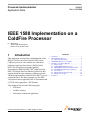
1
Freescale Semiconductor
Application Note
AN3625
Rev. 0, 06/2008
IEEE 1588 Implementation on a
ColdFire Processor
by: Michal Princ
System Application Engineer
Roznov Czech System Center
1
Introduction
This application note describes implementation of the
IEEE® 1588 Precision Time Protocol (PTP) on the
ColdFire® processor. The solution uses a hardware
platform comprising Freescales's ColdFire family
MCF5234 microprocessor and the National
Semiconductor DP83640 PHYTER® High Precision –
IEEE 1588 Single Port Fast Ethernet Transceiver that
supports hardware time-stamping of Ethernet packets.
The demo application uses the new M5234BCC low cost
evaluation board. The demo software uses the IEEE
1588 protocol stack supplied by IXXAT Automation and
a TCP/IP stack supplied by CMX Systems.
This document discusses the following topics:
• PTP basics
• ColdFire solution
• Description of the demo application
© Freescale Semiconductor, Inc., 2008. All rights reserved.
Contents
1
2
3
4
5
Introduction . . . . . . . . . . . . . . . . . . . . . . . . . . . . . . . . . . . 1
IEEE 1588 Basic Overview . . . . . . . . . . . . . . . . . . . . . . . 2
2.1 Synchronization Principle . . . . . . . . . . . . . . . . . . . . 3
IXXAT IEEE 1588 Protocol on ColdFire . . . . . . . . . . . . . 5
Description of the Demo Application . . . . . . . . . . . . . . . . 7
4.1 Demo Concept. . . . . . . . . . . . . . . . . . . . . . . . . . . . . 7
4.2 ColdFire MCF523x Microprocessor. . . . . . . . . . . . . 9
4.3 M5234BCCKIT: Business Card Controller KIT . . . 11
4.4 IXXAT IEEE 1588 PTP Protocol Software. . . . . . . 12
4.5 User Interface . . . . . . . . . . . . . . . . . . . . . . . . . . . . 13
4.6 Measuring the Clock Synchronicity . . . . . . . . . . . . 19
4.7 Microprocessor Usage. . . . . . . . . . . . . . . . . . . . . . 20
Conclusion. . . . . . . . . . . . . . . . . . . . . . . . . . . . . . . . . . . 21
IEEE 1588 Basic Overview
2
IEEE 1588 Basic Overview
The IEEE 1588 standard is known as Precision Clock Synchronization Protocol for Networked
Measurement Control Systems, or PTP for short. The IEEE 1588 PTP allows clocks distributed across an
Ethernet network to be accurately synchronized using a process where the distributed nodes exchange
timestamped messages.
The technology behind the standard is originally developed by Agilent and used for distributed measuring
and control tasks. The challenge is to synchronize networked measuring devices with each other in terms
of time, therefore able to record measured values providing them with a precise system timestamp. Based
on this timestamp, the measured values can then be correlated with each other.
Typical applications of the IEEE 1588 time synchronization include:
• Time-sensitive telecommunication services that require precision time synchronization between
communicating nodes
• Industrial network switches that synchronize sensors and actuators over a single wire distributed
control network to control an automated assembly process
• Powerline networks that synchronize across large-scale distributed power grid switches to enable
smooth transfer of power
• Test/measurement devices that must maintain accurate time synchronization with the device under
test in many different operating environments
These applications require precise clock synchronization between devices with accuracy in the
sub-microsecond range. It is a remarkable feature of the IEEE 1588 that this synchronization precision is
achieved via the regular Ethernet connectivity using standard Ethernet frames. This must be assumed to
be non real-time capable.
This solution allows nearly any device of any performance to participate in high precision synchronized
networks that are simple to operate and configure.
Other key benefits of the IEEE 1588 protocol include:
• IEEE 1588 protocol enables rapid convergence (less than a minute) to sub-microsecond time
synchronization between heterogeneous distributed devices with different clocks, resolution, and
stability.
• The IEEE 1588 network configures and segments itself automatically. Each node uses the best
master clock algorithm (BMC) to determine the best clock in the segment. Every PTP node stores
its features within a specified dataset. These features are transmitted to other nodes within its sync
telegrams. Based on this, other nodes are able to synchronize their datasets with the features of the
actual master and can adjust their clocks. Due to the cyclic running of the BMC, nodes can also be
connected or removed during propagation time (hot swapping).
• Simple configuration and operation with low compute resource and network bandwidth
consumption
IEEE 1588 Implementation on a ColdFire Processor, Rev. 0
2
Freescale Semiconductor
IEEE 1588 Basic Overview
2.1
Synchronization Principle
In Ethernet systems, unpredictable collisions due to the CSMA/CD procedure may lead to time packages
being delayed or disappearing completely. For this reason, the IEEE 1588 defines a special clock
synchronization procedure.
The process starts with one node (master clock) transmitting a sync telegram that contains the estimated
transmission time. The exact transmission time of the sync telegram is captured by a clock and transmitted
in a second follow up message. By comparing the timestamp information contained within the first and
second telegrams against its own clock, the receiver can calculate the time difference between its own
clock and the master clock, see Figure 1. Sync and follow-up messages are sent as multicast.
System A
(Master)
System B
(Slave)
t0
t0 = timestamp
of sync msg sent
t0 value
sent in follow-up msg
sync m
sg
t1
t1 = timestamp
of sync msg received
follow
-u
(includ p msg
es t0)
Equation 1:
t1 - t0 = offset + delay
Figure 1. Offset and Delay Measurement — Sync Message, Follow-Up Message
The telegram propagation time is determined cyclically in a second transmission process between the slave
and the master (delay telegrams). The slave can then correct its clock and adapt it to the current bus
propagation time, see Figure 2. Delay_req and delay_resp messages are point-to-point but sent with a
multicast address for simplicity.
IEEE 1588 Implementation on a ColdFire Processor, Rev. 0
Freescale Semiconductor
3
IEEE 1588 Basic Overview
System A
(Master)
t3
System B
(Slave)
_requ
delay
msg
t2
t2 = timestamp
of delay_req msg sent
delay_
re
(includ sp msg
es t3)
t3 = timestamp
of delay_req msg received
Equation 2:
t3 – t2 = delay - offset
Figure 2. Offset and Delay Measurement — Delay Messages
Figure 3 serves as an example of the IEEE 1588 synchronization message sequence.
100
102
104
Master Clock
PTP Appl.
G/MII
t0
Estimated
Send Time
(100)
Precise
Send
Time
(101)
Slave Clock
G/MII
PTP Appl.
104
SYNC(100??
)
t1
FOLLOW_U
P(101!)
106
t3
B
DELAY_REQ
t2
108
110
112
Precise
Receive
Time
(108)
DELAY_RES
P(108)
Key Equations:
Example:
A = t1 – t0 = Delay + Offset
A = 106 – 101 = 5
B = t3 - t2 = Delay – Offset
B = 108 – 111 = -3
Delay = (A+B) / 2
Delay = (5-3) / 2 = 1
Offset = (A-B) / 2
Offset = (5+3) / 2 = 4
A
106
Precise
Receive
Time (106)
108
Offset
Computation
110
Precise
Send Time
(111)
112
114
116
UDP port 319: Sync and
Delay_Req
UDP port 320: Follow_up,
Delay_Resp, and Mgmt
Figure 3. IEEE 1588 Synchronization Message Sequence
For more information about the IEEE 1588 standard, visit the web page for the National Institute of
Standards and Technology.
IEEE 1588 Implementation on a ColdFire Processor, Rev. 0
4
Freescale Semiconductor
IXXAT IEEE 1588 Protocol on ColdFire
3
IXXAT IEEE 1588 Protocol on ColdFire
The PTP protocol can be implemented in software using a standard Ethernet module. However, because
the timestamp information is applied at the application level, the delay fluctuation introduced by the
software stack running on both master and slave devices mean that only a limited precision can be
achieved, see Figure 4.
Now, it's
9:28 !
Master Clock
Slave Clock
OK, thanks
9:28 !
Variable delay introduced
by the Network due to the
topology:
PTP
Milliseconds
of delay and
variation
introduced
by protocol
stack
UDP
IP
•Hundreds of nanoseconds
to microseconds for
repeaters & switches
•Milliseconds for routers
MAC
PHY
PTP Packet
PTP
UDP
IP
MAC
Network
Milliseconds
of delay and
variation
introduced
by protocol
stack
PHY
Now it's 9:28
Figure 4. Software Timestamp Implementation
Master Clock
Slave Clock
OK, thanks
9:28 !
Now, it's
…
PTP
PTP
UDP
UDP
IP
IP
MAC
MAC
PHY
Network
PHY
… 9:28 !
PTP Packet
Now it's 9:28
Figure 5. Hardware Timestamp Implementation
IEEE 1588 Implementation on a ColdFire Processor, Rev. 0
Freescale Semiconductor
5
IXXAT IEEE 1588 Protocol on ColdFire
It is possible to minimize the impact of the protocol stack delay by generating/marking timestamps as close
as possible to the physical interface boundary, see Figure 5. Dedicated hardware time-stamping allows
synchronization with significantly improved precision achieved.
Freescale Semiconductor’s ColdFire M5234BCC Evaluation Board with the National Semiconductor
DP83640 PHYTER High Precision – IEEE 1588 Single Port Fast Ethernet Transceiver serves as an HW
platform that fulfills these requirements. Together with the IEEE 1588 PTP protocol software from IXXAT
the leading industrial protocol vendor, this allows customers to develop precise IEEE 1588 solutions.
Figure 6 describes the hardware and software components of this joint solution.
Application
Management
Slave
SIS
Control
(Best Master Clock Algorithm)
Master
Dispatcher
Time Stamp Unit (TSU)
IXXAT IEEE
1588 Engine
Network Interface
Clock Interface (CIF)
CMX TCP/UDP/IP
Fast Ethernet Controller
MCF5234
MII
MII
Time Stamp
Insertion
Adjustable
HW Clock
NSC DP83640T
PHYTER®
Ethernet
Figure 6. IEEE 1588 Protocol Implementation on ColdFire
This system relies on timestamp insertion and an adjustable HW clock. Both are implemented by DP83640
PHYTER. The PHYTER IEEE 1588 transmit parser monitors transmit packet data to detect IEEE 1588
version 1 and version 2 event messages. After any PTP event message is detected, the device captures the
transmit timestamp and provides it to the IXXAT IEEE 1588 stack software through the media
independent interface (MII). Similiarly, the PHYTER receive parser monitors receive packet data to detect
IEEE 1588 version 1 and version 2 event messages. Upon detection of a PTP event message, the device
captures the received timestamp, inserts it into the received packet at fixed locations within the PTP
message, and passes the whole message through the MII to the IXXAT IEEE1588 stack software. This is
how received timestamps are delivered to the IXXAT IEEE 1588 engine.
The IXXAT IEEE 1588 engine of the slave device processes all the PTP received messages. It makes
adjustments to its own clock (the DP83640 PHYTER IEEE 1588 clock) based on the extracted
timestamps. The method used to update the DP83640 PHYTER clock value depends on the difference in
IEEE 1588 Implementation on a ColdFire Processor, Rev. 0
6
Freescale Semiconductor
Description of the Demo Application
the clock time values. During the initial synchronization stage while the master and slave clocks are far
apart, a step adjustment or a direct time set is applied. Later, when the time difference between the master
clock and the slave clock is smaller, the rate adjustment (clock frequency adjustment) method is used.
Setting the DP83640 PHYTER registers is performed through the MII interface.
4
Description of the Demo Application
4.1
Demo Concept
The demo application showing the PTP implementation on ColdFire processors consists of several boards
and components. Some of these are essential and others are optional. The minimum configuration
includes:
• M5234BCC board with the PTP stack configured as the master device
• M5234BCC board with the PTP stack configured as the slave device
• PC with the FreeMASTER software, serial line cable/P&E USB Multilink debug module
• Power supplies, Ethernet crossover type cable
• Oscilloscope (optional)
The demo can be configured in a back-to-back (point-to-point) configuration where two boards are
connected directly using the crossover Ethernet cable. This deals with a simple type of connection often
used for evaluating the system accuracy and the overall performance. The user interface to the applications
running on both the master and the slave is managed through the FreeMASTER GUI. FreeMASTER is a
visualization tool that runs on a PC. There are two ways to establish the connection between FreeMASTER
(running on the PC) and the BCC boards, through a standard RS-232 serial line, or through the P&E USB
BDM Multilink debugger. The back-to-back configuration is illustrated in Figure 7.
It is possible to extend the system to include additional PTP slaves (one or several). An Ethernet switch
provides the connection between all ColdFire BCC boards. As an alternative to the FreeMASTER GUI, a
Telnet console can be used for monitoring and control of the PTP activities. Figure 8 shows a configuration
with one master and two slave devices.
This is the concept used in creating the Freescale ColdFire MCF5234 Based IEEE 1588 Precision Time
Protocol demo, see Figure 9. The M5234BCC board with the blue Ethernet connector is loaded with the
PTP stack and is configured as a master. The other two M5234BCC boards are loaded with the PTP stack
and are configured as slaves.
The demo can work equally well if one of the BCC slaves or the BCC master is replaced by the
PowerQUICC processor family with NSC PHYTER (in some cases without it, where the hardware
timestamp is built into the PowerQUICC MAC). For more information about the developed PowerQUICC
based IEEE 1588 systems go to www.freescale.com.
IEEE 1588 Implementation on a ColdFire Processor, Rev. 0
Freescale Semiconductor
7
Description of the Demo Application
FreeMASTER
M5234BCC
IEEE1588 Master
PPS
signal
Crossover
Ethernet
cable
RS232
or
P&E USB
Multilink
FreeMASTER
M5234BCC
IEEE1588 Slave
Figure 7. Back-to-Back Configuration of the Demo
M5234BCC
IEEE1588 Master
Telnet console
Ethernet Network
Switch
RS232
or
P&E USB
Multilink
PPS
signal
FreeMASTER
M5234BCC
IEEE1588 Slave
M5234BCC
IEEE1588 Slave
Figure 8. Demo Extended to Include Multiple Nodes
IEEE 1588 Implementation on a ColdFire Processor, Rev. 0
8
Freescale Semiconductor
Description of the Demo Application
Figure 9. Freescale ColdFire MCF5234 Based IEEE 1588 Demo
4.2
ColdFire MCF523x Microprocessor
The MCF523x is a family of highly-integrated 32-bit microprocessors based on the V2 ColdFire core. It
features a 16- or 32-channel enhanced time processor unit (eTPU), 64 Kbytes of internal SRAM, a 2-bank
SDRAM controller, four 32-bit timers with DMA request capability, a 4-channel DMA controller, up to
two CAN modules, three UARTs, and a queued SPI. The MCF523x family has been designed for
general-purpose industrial control applications.
This 32-bit device is based on the V2 ColdFire reduced instruction set computer (RISC) core operating at
a core frequency of up to 150 MHz and a bus frequency of up to 75 MHz. On-chip modules include the
following:
• V2 ColdFire core with an enhanced multiply-accumulate unit (EMAC) providing 144 Dhrystone
2.1 MIPS at 150 MHz
• eTPU with 16 or 32 channels, 6 Kbytes of code memory, and 1.5 Kbytes of data memory with
eTPU debug support
• 64 Kbytes of internal SRAM
• External bus speed of half the CPU operating frequency (75 MHz bus at 150 MHz core)
• 10/100 Mbps bus-mastering Ethernet controller
IEEE 1588 Implementation on a ColdFire Processor, Rev. 0
Freescale Semiconductor
9
Description of the Demo Application
•
•
•
•
•
•
•
•
•
•
•
•
•
•
•
•
•
•
8 Kbytes of configurable instruction/data cache
Three universal asynchronous receiver/transmitters (UARTs) with DMA support
Controller area network 2.0B (FlexCAN module)
Optional second FlexCAN module multiplexed with the third UART
Inter-integrated circuit (IIC) bus controller
Queued serial peripheral interface (QSPI) module
Hardware cryptography accelerator (optional)
Random number generator
DES/3DES/AES block cipher engine
MD5/SHA-1/HMAC accelerator
4-channel, 32-bit direct memory access (DMA) controller
4-channel, 32-bit input capture/output compare timers with optional DMA support
4-channel, 16-bit periodic interrupt timers (PITs)
Programmable software watchdog timer
Interrupt controller capable of handling up to 126 interrupt sources
Clock module with phase locked loop (PLL)
External bus interface module including a 2-bank synchronous DRAM controller
32-bit, non-multiplexed bus with up to eight chip select signals that support page-mode FLASH
memories
Figure 10. MCF523x Family
For more information, refer to MCF523x Reference Manual, MCF5235RM.
IEEE 1588 Implementation on a ColdFire Processor, Rev. 0
10
Freescale Semiconductor
Description of the Demo Application
4.3
M5234BCCKIT: Business Card Controller KIT
The M5234BCCKIT offers a complete low-cost method for evaluation of the Freescale MCF5234
ColdFire microprocessor. It is similar to the M5235BCCKIT but includes the DP83640T PHYTER High
Precision – IEEE 1588 Precision Time Protocol (PTP) Single Port Fast Ethernet Transceiver, supplied by
National Semiconductor. The M5234BCC module comes with:
• 10/100TX Ethernet port with the NSC DP83640T PHYTER, IEEE 1588 capability, RJ45
connector, three status indicators, and an auto connection detection.
• 2 MByte flash (16-bit, external)
• 16 MBytes SDRAM (32-bit, external)
• 25 MHz reference crystal, up to 100 MHz operation
• MCU Port, 50-pin GPIO port with 1 x 1Mb CAN I/O
• ETPU Port, 20 pins, and 16 channels with +V supply
• BUS port, 34 pins, 64 K address, 8-bit data bus, and three selects
• BDM / JTAG Port, 26 pins, and a development port
• COM Port (UART0) with RS232 DB9-S ribbon connector
• CAN port with 1 Mbaud transceiver on the MCU Port
• RESET switch and indicator
• ABORT (IRQ7) switch
• Regulated +3.3V and +1.5V power supply with indicator
While the M5234BCCKIT specifically incorporates the National Semiconductor DP83640 PHYTER, the
IEEE 1588 capability can be easily supported on any Ethernet-enabled ColdFire device. The standard
Ethernet controller used across the ColdFire family combined with the National Semiconductor DP83640
PHYTER allows the IXXAT Automation IEEE 1588 stack and the CMX TCP/IP stack to be ported to any
ColdFire device with minimal effort.
For more information about the M5234 Business Card Controller KIT, refer to the M5234BCC Board's
User Manual, M5234BCCUM.
The DP83640 Precision PHYTER device delivers high precision clock synchronization for real time
industrial connectivity based on the IEEE 1588 standard. The DP83640 has deterministic low latency and
can be interfaced easily to any other device within the ColdFire or PowerQUICC family with no further
hardware customization. The integrated IEEE 1588 functionality allows system designers the flexibility
and precision of a close-to-wire timestamp. The DP83640 PHYTER supports the IEEE 1588 real time
Ethernet applications by providing hardware support for three time critical elements.
• IEEE 1588 synchronized clock generation
• Packet timestamps for clock synchronization (8 ns resolution)
• Event triggering and timestamping through GPIO
By combining the capabilities described above, the DP83640 provides advanced and flexible support for
systems using IEEE1588.
IEEE 1588 Implementation on a ColdFire Processor, Rev. 0
Freescale Semiconductor
11
Description of the Demo Application
The DP83640 provides features for controlling the clock operation in slave mode. The clock value can be
updated to match the master clock in several ways. The clock can also be programmed to adjust its
frequency to compensate for drift.
The DP83640 supports real time triggering activities and captures real time events to report to the
microcontroller. Controlled devices can be connected to the DP83640 through GPIO pins.
For a more detailed discussion on configuring the IEEE 1588 features, refer to the National Semiconductor
Ethernet PHYTER® Software Development Guide, available at NSC web pages.
4.4
IXXAT IEEE 1588 PTP Protocol Software
The IEEE 1588 protocol software enables simple rapid development of IEEE 1588 compliant devices.
Developed by IXXAT Automation GmbH, the IEEE 1588 protocol software has a modular structure
ensuring fast integration into the target system. For access to the UDP/IP socket, the interfaces to the target
platform are compiled in a separate adaptation layer (network interface) considerably simplifying porting
to the target system, see Figure 6.
The software is completely independent of the operating system and therefore can also be used in
applications without an operating system (superloops). The only requirement is a multicast-compatible
UDP/IP stack. The portable embedded TCP/IP stack developed by CMX Systems, Inc., is chosen for this
demo application.
4.4.1
Functionality
The IEEE 1588 V1 software package includes a full implementation of the standard for Ethernet with the
following functionality:
• Ordinary clock
• Boundary clock
• Best master clock algorithm
• Configuration and scaling via central configuration file
• Management API
4.4.2
Platform Requirements
The platform must support a few basic features suitable for IEEE 1588 software porting:
• TCP/IP stack — The TCP/IP stack must provide a standard UDP interface. The transmitting and
receiving functions must provide a non-blocking mode. The options IP_ADD_MEMBERSHIP,
IP_DROP_MEMBERSHIP, and SO_REUSEADDR are required. For implementations using more
than one channel to Ethernet segments, the option IP_MULTICAST_IF is required.
• Timer — The IEEE 1588 stack uses an internal timer module. The platform must trigger this
module with an interval of 20 milliseconds. Only low precision is required.
• Clock — The platform must provide some kind of a real-time clock. In this demo application, it
deals with the DP83640 PHYTER clock. The drift and offset of this clock is adjustable by software.
IEEE 1588 Implementation on a ColdFire Processor, Rev. 0
12
Freescale Semiconductor
Description of the Demo Application
•
4.5
For implementations that use SW time-stamping, the time value must be accessible via software.
A free running timer can also be used as a real-time clock.
Interrupts — For implementations that use SW time-stamping the platform must provide interrupts
on sending and receiving Ethernet packets.
User Interface
The ColdFire MCF5234 based IEEE 1588 demo application can be accessed by:
• A FreeMASTER running on a PC connected to the MCF5234BCC via a standard RS232 serial
cable or via the P&E USB BDM Multilink debugger
• A Telnet console
4.5.1
FreeMASTER Communication
The FreeMASTER software was designed to provide a run-time application-debugging, diagnostic, and
demonstration tool for the development of algorithms and applications. It runs on a PC connected to the
M5234BCC via an RS232 serial cable and the UART0 COM port (by default). A small program resident
in the microprocessor communicates with the FreeMASTER software to provide status information to the
PC and processes control information from the PC. FreeMASTER software executing on a PC uses a part
of Microsoft Internet Explorer to enable an HTML and JScript-based graphical user interface.
NOTE
FreeMASTER version 1.3.6 or higher is required and the communication
plug-ins; BDM communication plug-in for Freescale HCS08, HC(S)12, and
ColdFire V1, V2, V3, and V4 microcontrollers must be installed. The
FreeMASTER application can be downloaded at www.freescale.com.
FreeMASTER features:
• Graphical environment
• Easy to understand navigation
• Simple RS232 connection
• Run-time access to embedded-side C variables
• Visualization of real-time data in scope window
• Acquisition of fast data transitions using the recorder
• Built-in support for standard variable types (integer, floating point, and bit fields)
• Value interpretation using custom defined text messages
• Several built-in transformations for real type variables
• Automatic C-application variable extraction from Metroworks CodeWarrior output files
(ELF/DWARF1/2, Map Files,...)
• Demo mode with password protection support
• HTML-based description or navigation pages
• HTML and JScript-based graphical control page
IEEE 1588 Implementation on a ColdFire Processor, Rev. 0
Freescale Semiconductor
13
Description of the Demo Application
•
•
ActiveX interface to enable VBScript or JScript control over embedded application
Remote communication server enabling a connection to target board over a network, including the
Internet
When the FreeMASTER project file (*.pmp) is opened, the main window is displayed on the screen. The
FreeMASTER window consists of three panes: the project tree pane on the left side, the detail view pane
on the top, and the variable watch pane at the bottom.
The detail view pane displays the control page that enables the PTP to be started or stopped by clicking on
the corresponding buttons. It also allows the course of the actual offset, average offset, and standard
deviation variables to be viewed in a graph. The clock offset histogram is displayed on the main control
page, see Figure 11.
Figure 11. FreeMASTER Control Page
IEEE 1588 Implementation on a ColdFire Processor, Rev. 0
14
Freescale Semiconductor
Description of the Demo Application
Selected PTP stack variables are displayed on the variable watch pane:
• Current Time (s)
• Actual Offset (ns)
• Average Offset (ns)
• Standard Deviation (ns)
• Master to Slave Delay (ns)
• Slave to Master Delay (ns)
• One Way Delay (ns)
These variables can not be modified using FreeMASTER. The actual values can only be viewed.
The actual clock offset can be displayed in a graph using the oscilloscope native component of
FreeMASTER, see Figure 12.
Figure 12. FreeMASTER Detail View Pane Showing Oscilloscope Trace
IEEE 1588 Implementation on a ColdFire Processor, Rev. 0
Freescale Semiconductor
15
Description of the Demo Application
To set up the demo and the FreeMASTER properly follow the instructions written in the ColdFire based
IEEE1588 Demo Quick Guide document. For more information go to www.freescale.com.
The possibility to use FreeMASTER for the IEEE 1588 applications setting, monitor, and control is helpful
when there is a crossover point-to-point connection without any switch or hub (back-to-back connection).
In this case the Telnet console cannot be used, however the FreeMASTER interface can be used. The
graphical interpretation of the monitored PTP variables is another advantage of the FreeMASTER GUI.
4.5.2
Telnet Console
Embedded Shell is a CMX TCP/IP facility that allows the user to execute commands on the target system
through the Telnet. In addition to the standard shell utilities provided by the CMX software, the user can
add other commands to the shell. For example, testing activities, setting up application parameters, and
monitoring and control of the PTP activities. The list of the embedded shell commands is summarized in
Table 1.
Table 1. Embedded Shell Commands Overview
Command
Functionality
help
Usage — help [cmd]
Display help information of command cmd
ver
Usage — ver
Display version string
netstat
Usage — netstat [-a|m]
netstat -i[m]
netstat -r
netstat -s
netstat -b
Display network active connections
-a display all
-m display multicast information
-o display timers
-i display interface table
-r display routing table
-s display statistics
-b display buffers usage
ifconfig
Usage — ifconfig [ifname [address|options]]
Configure network interfaces.
Options:
• address – set the IP address
• netmask mask – set the netmask
• dstaddr addr – set the destination IP address
• mtu n – set the maximum transfert unit
• up – activate the interface
• down – shutdown the interface
IEEE 1588 Implementation on a ColdFire Processor, Rev. 0
16
Freescale Semiconductor
Description of the Demo Application
Table 1. Embedded Shell Commands Overview (continued)
Command
Functionality
arp
Usage — ifconfig
Configure network interfaces.
Options:
• address – set the IP address
• netmask mask – set the netmask
• dstaddr addr – set the destination IP address
• mtu n – set the maximum transfert unit
• up – activate the interface
• down – shutdown the interface
route
Usage — route
route add gateway
route del target
Display routing table:
add – adds a static route
del – deletes a static route
target – target address, default for default route
netmask Nm – netmask for the target network address
gateway – gateway address, must be reachable on a local network
ping
Usage — ping addr
Send ICMP ECHO_REQUEST packets to network hosts
h – Print this help
t – Send an infinite number of request
n number – Send the specified number of requests
l size – Set the size of the requests
i ttl – Set the time-to-live value of the requests
w delay – Set the timeout delay for receiving echo reply
addr– IP address of destination host
exit
Usage — exit
Terminate shell session or go back to upper level
lsmod
Usage — lsmod
Display list of modules
date
Usage — date
or: date
Display or set current date and time
ptp
Usage — ptp start|stop
start – Starts the IXXAT IEEE1588 engine
stop – Stops the IXXAT IEEE1588 engine
ptpdisplay
Usage — ptpdisplay
Sets on/off displaying the actual sync parameters
Options:
• silent – silent mode
• offs – actual offset from master
• mtsd – actual master to slave delay
• stmd – actual slave to master delay
• owd – actual one way delay
• stdDev – actual standard deviation of the offset
• meanDrft – actual mean drift in ppb
IEEE 1588 Implementation on a ColdFire Processor, Rev. 0
Freescale Semiconductor
17
Description of the Demo Application
Table 1. Embedded Shell Commands Overview (continued)
Command
Functionality
ptpparam
Usage — ptpparam [option value]
Enables changing the clock data set member variables
Options:
• stratum //stratum value could be 0–4 and 255 only, see the PTP specifications
• clk_id //indicate the nature, expected absolute accuracy, and epoch of a given
clock, see the PTP specifications
• clock_variance //inherit accuracy variance
• preferred //is clock preferred to be master? 0=no, 1=yes
• sync_interval //interval in seconds between successive sync messages issued by
master clocks; sync_interval value could be 0-255 only
• subd_name //subdomain name, see the PTP specifications
• current_utc_offset //offset of universal coordinated time (UTC) to temps atomique
international (TAI) since June 30,1972
• leap_59 //leap_59 value could be 0 or 1, see the PTP specifications
• leap_61 //leap_61 value could be 0 or 1, see the PTP specifications
• epoch_number //current number of times the 32-bit seconds clock has rolled over
since the PTP epoch; the next epoch in PTP-time begins in January 2106
ptpsyncdate
Usage — ptpsyncdate
Synchronize the TCP/IP stack date and time with the accurate PTP engine date and
time.
savenetparams
Usage — savenetparams
Save the basic network configuration parameters (IP address, netmask and gateway)
into the flash to be restored after the device reset.
telnet
Usage — telnet start|stop
start – Starts telnet server
stop – Stops telnet server
The most commonly used commands are those enabling the configuration of the network interface. Apply
the following commands to change the essential network configuration and the clock data settings
parameters:
ifconfig eth0 <IP address> changes the IP address
ifconfig eth0 netmask <netmask> changes the NETMASK
route add default <gateway> changes the GATEWAY
ptpparam preferred < 0=no, 1=yes > // defines whether the clock preferred is to be master or slave
savenetparams saves the basic network configuration parameters into the flash
NOTE
It is not possible to change the MAC address of the board through the
command shell. This can be done only through the FreeMASTER GUI.
After the MAC address is changed and saved into the flash memory, the
Telnet console can be started and used as the IEEE 1588 demo application
interface.
IEEE 1588 Implementation on a ColdFire Processor, Rev. 0
18
Freescale Semiconductor
Description of the Demo Application
While using the Telnet console, the embedded command shell is accessible after the communication with
the M5234BCC board is established. This is done by entering the command open <defined IP address>
into the Telnet Client.
Figure 13. CMX TCP/IP Telnet Console
4.6
Measuring the Clock Synchronicity
To measure the synchronicity of the clocks, the DP83640 PHYTER provides an option to generate a
pulse-per-second (PPS) signal on all clocks. This allows them to be compared using the oscilloscope.
These signals are generated directly from the DP83640 PHYTER clock and routed to the selected GPIO
pin.
This PPS signal is not routed to any of the M5234BCC board headers and the user needs to attach the
oscilloscope probe directly to the DP83640 PHYTER pin. It is possible to see on the oscilloscope screen
and how the individual slave clocks are synchronized with the master clock, see Figure 14.
The results of the long-term clock synchronization accuracy test performed by the IXXAT are as follows:
• Average clock offset: 2 ns
• Standard deviation: 12 ns
• Peak-to-peak range: – 42 ns to +112 ns
IEEE 1588 Implementation on a ColdFire Processor, Rev. 0
Freescale Semiconductor
19
Description of the Demo Application
Master
Slave 1
Slave 2
Figure 14. Oscilloscope Screen-Shot — Measuring the Clock Synchronicity (PPS)
4.7
Microprocessor Usage
Table 2 shows how much memory is needed to run the application.
Table 2. Memory Usage in Bytes
Memory
Available
Used
FLASH (external)
2M
222 K
SDRAM (external)
16 M
68 K
IEEE 1588 Implementation on a ColdFire Processor, Rev. 0
20
Freescale Semiconductor
Conclusion
5
Conclusion
This application note describes an IEEE 1588 Precision Time Protocol demo application targeted at the
MCF5234 ColdFire Processor and the M5234BCC Evaluation Board equipped with the NSC DP83640
PHYTER High Precision – IEEE 1588 Single Port Fast Ethernet Transceiver. This solution can be easily
ported to other processors from the ColdFire family.
The demo system can be targeted to applications requiring extremely precise clock synchronization
between devices with accuracy in the sub-microsecond range. Typical applications include industrial
network switches, time-sensitive telecommunication services, powerline networks, and test/measurement
devices.
Freescale is collaborating with IXXAT, a leading industrial protocol vendor, to offer a complete
preconfigured commercial off-the-shelf system solution running the IEEE 1588 protocol.
For more information and updates go to www.freescale.com.
IEEE 1588 Implementation on a ColdFire Processor, Rev. 0
Freescale Semiconductor
21
How to Reach Us:
Home Page:
www.freescale.com
Web Support:
http://www.freescale.com/support
USA/Europe or Locations Not Listed:
Freescale Semiconductor, Inc.
Technical Information Center, EL516
2100 East Elliot Road
Tempe, Arizona 85284
+1-800-521-6274 or +1-480-768-2130
www.freescale.com/support
Europe, Middle East, and Africa:
Freescale Halbleiter Deutschland GmbH
Technical Information Center
Schatzbogen 7
81829 Muenchen, Germany
+44 1296 380 456 (English)
+46 8 52200080 (English)
+49 89 92103 559 (German)
+33 1 69 35 48 48 (French)
www.freescale.com/support
Japan:
Freescale Semiconductor Japan Ltd.
Headquarters
ARCO Tower 15F
1-8-1, Shimo-Meguro, Meguro-ku,
Tokyo 153-0064
Japan
0120 191014 or +81 3 5437 9125
[email protected]
Asia/Pacific:
Freescale Semiconductor Hong Kong Ltd.
Technical Information Center
2 Dai King Street
Tai Po Industrial Estate
Tai Po, N.T., Hong Kong
+800 2666 8080
[email protected]
For Literature Requests Only:
Freescale Semiconductor Literature Distribution Center
P.O. Box 5405
Denver, Colorado 80217
1-800-441-2447 or 303-675-2140
Fax: 303-675-2150
[email protected]
Document Number: AN3625
Rev. 0
06/2008
Information in this document is provided solely to enable system and software
implementers to use Freescale Semiconductor products. There are no express or
implied copyright licenses granted hereunder to design or fabricate any integrated
circuits or integrated circuits based on the information in this document.
Freescale Semiconductor reserves the right to make changes without further notice to
any products herein. Freescale Semiconductor makes no warranty, representation or
guarantee regarding the suitability of its products for any particular purpose, nor does
Freescale Semiconductor assume any liability arising out of the application or use of any
product or circuit, and specifically disclaims any and all liability, including without
limitation consequential or incidental damages. “Typical” parameters that may be
provided in Freescale Semiconductor data sheets and/or specifications can and do vary
in different applications and actual performance may vary over time. All operating
parameters, including “Typicals”, must be validated for each customer application by
customer’s technical experts. Freescale Semiconductor does not convey any license
under its patent rights nor the rights of others. Freescale Semiconductor products are
not designed, intended, or authorized for use as components in systems intended for
surgical implant into the body, or other applications intended to support or sustain life,
or for any other application in which the failure of the Freescale Semiconductor product
could create a situation where personal injury or death may occur. Should Buyer
purchase or use Freescale Semiconductor products for any such unintended or
unauthorized application, Buyer shall indemnify and hold Freescale Semiconductor and
its officers, employees, subsidiaries, affiliates, and distributors harmless against all
claims, costs, damages, and expenses, and reasonable attorney fees arising out of,
directly or indirectly, any claim of personal injury or death associated with such
unintended or unauthorized use, even if such claim alleges that Freescale
Semiconductor was negligent regarding the design or manufacture of the part.
RoHS-compliant and/or Pb-free versions of Freescale products have the functionality
and electrical characteristics as their non-RoHS-compliant and/or non-Pb-free
counterparts. For further information, see http://www.freescale.com or contact your
Freescale sales representative.
For information on Freescale’s Environmental Products program, go to
http://www.freescale.com/epp.
Freescale™ and the Freescale logo are trademarks of Freescale Semiconductor, Inc.
All other product or service names are the property of their respective owners.
© Freescale Semiconductor, Inc. 2008. All rights reserved.