1
INTRODUCTION
TO THE OWNER
Read this manual before operating your mower. The information presented will prepare you to do a better
and safer job, Keep this manual handy for ready reference.
The mower you have purchased has been carefully engineered and manufactured to provide dependable
-and satisfactory use, Like all mechanical products, it will require cleaning and upkeep. Lubricate the
mower as specified. Observe all safety information in this manual and safety decals on the mower and
tractor.
For service, your authorized dealer has trained mechanics, genuine service parts, and the necessary tools
and equipment to handle all your needs.
Use only genuine service parts. Substitute parts may not meet standards required for safe and satisfactory
operation.
Model MM60 Rotary Mower
Record the serial number of your mower:
Serial Number (see Safety Decal page for location)
Provide this information to your dealer to obtain correct repair parts.
Throughout this manual, the term NOTICE is used to indicate that failure to observe this instruction can
cause damage to equipment. The terms CAUTION, WARNING and DANGER are used in conjunction with
the Safety-Alert Symbol, (a triangle with an exclamation mark), to indicate the degree of hazard for items of
personal safety.
The Safety-Alert Symbol means ATTENTION! BECOME ALERT!
YOUR SAFETY IS INVOLVED!
Denotes a reminder of safety practices or directs attention to unsafe practices
which could result in personal injury if proper precautions are not taken.
Denotes a hazard exists which can result in injury or death if proper precautions
are not taken.
!
1 -
# .
Denotes an extreme intrinsic hazard exists which would result in high probability
of death or irreparable injury if proper precautions are not taken.
1
INTRODUCTION
GENERAL INFORMATlON
The purpose of this manual is to assist the operator in maintaining and operating this mower. Read
it carefully. It furnishes information and instructions
that will help you achieve years of dependable
performance. These operating and maintenance
instructions have been compiled from extensive
field experience and engineering data. Some
information may be general in nature due to
unknown and varying conditions. However, you
should be able to develop operating procedures
suitable to your particular situation.
The illustrations and data used in this manual were
current at the time of printing, but due to possible
in-line production changes, your machine may
vary slightly in detail. We reserve the right to
redesign and change the machine as may be
necessary without notification.
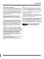
Some illustrations in this manual
show the mower with safety shields removed
to provide a better view. The mower should
never be operated with any safety shielding
removed.
1 -
,
Throughout this manual, references are made to
right and left directions. These are determined by
standing behind the equipment and facing the
direction of forward travel. Blade rotation is clockwise as viewed from the top of the mower.
CONTENTS
INTRODUCTION
TO THE OWNER ...........................................................................................................................
GENERAL INFORMATION............................................................................................................
1
1
2
SAFETY INFORMATION
SAFETY RULES.............................................................................................................................
4
4
SET-UP AND ASSEMBLY
DEALER SET-UP INSTRUCTIONS.............................................................................................
UNPACKINGAND CHECKING PARTS ........................................................................................
MOUNTING MOWER LIFT SYSTEM ..........................................................................................
ASSEMBLING MOWER ..............................................................................................................
8
8
8
11
17
INSTALLING MOWER
INSTALLING MOWER TO TRACTOR .........................................................................................
DETACHING MOWER FROM TRACTOR ...................................................................................
18
OPERATION
ADJUSTING CUTTING HEIGHT .................................................................................................
PRE-OPERATION CHECK LIST .................................................................................................
OPERATING TECHNIQUE ..........................................................................................................
CUTTING PATTERNS.................................................................................................................
OPERATING YOUR MOWER WITH OTHER EQUIPMENT........................................................
28
29
30
31
32
33
MAINTENANCE
OWNER SERVICE .......................................................................................................................
LUBRICATION INFORMAllON......................................................................................................
BLADE INSPECTION ..................................................................................................................
BLADE SERVlClNG.....................................................................................................................
REPLACING BELTS ....................................................................................................................
DEALER LEVEL MAINTENANCE................................................................................... .........
SPINDLE REPAIR .......................................................................................................................
UNIVERSALJOINT REPAIR .......................................................................................................
GEARBOX MAINTENANCE ........................................................................................................
36
36
37
STORAGE
52
TROUBLESHOOTING
53
SPECIFICATIONS
55
WARRANTY SERVICE
56
21
25
38
39
41
42
43
47
49
3
SAFETY INFORMATION
Safety is a primary concern in the design and
manufacture of our products. Unfortunately,
our efforts to provide safe equipment can be
wiped out by a single careless act of an
operator.
In addition to the design and configuration of
equipment, hazard control and accident
prevention are dependent upon the awareness, concern, prudence and proper training
of personnel involved in the operation, transport, maintenance and storage of equipment.
It has been said, "The best safety device is
an informed, careful operator." We ask you to
be that kind of an operator.
4
SAFETY RULES
ATTENTION! BECOME ALERT!
YOUR SAFETY IS INVOLVED!
The designed and tested safety of this equipment
depends on it being operated within the limitations
explained in this manual.
Training
Safety instructions are important! Read this
manual, the tractor manual and all safety rules.
Know your controls and how to stop tractor
engine and mower quickly in an emergency.
Operators must be instructed in and be capable of the safe operation of the equipment, its
attachments and all controls. Do not allow
anyone to operate this equipment without
proper instructions,
Keep hands and body away from pressurized
lines. Use paper or cardboard, not body parts
to check for leaks. Hydraulic fluid (oil) under
pressure will penetrate skin causing serious
injury.
Make sure that all operating and service personnel know that in the event hydraulic fluid
penetrates skin, it must be surgically removed
within a few hours by a doctor familiar with this
form of injury, or gangrene may result.
Do not allow children or unqualified persons to
operate equipment.
SAFETY INFORMATION
Operational Safety
Preparation
You may not be able to stop the tractor safely if
Always wear relatively tight and belted clothing
the clutch or brake pedal mechanisms are
to avoid entanglement in moving parts. Wear
improperly adjusted, allowing them to contact
sturdy, rough-soled work shoes and protective
mower components.
equipment for eyes, hands, hearing and head.
When
the mower lift stops are installed as
Ensure that mower is properly mounted, adinstructed
in this manual, properly adjusted
justed and in good, operating Condition.
clutch and brake pedal mechanisms will not
Make sure mower driveline spring-activated
contact mower components. You should
locking collar slides freely and the balls are
frequently check that the tractor clutch and
seated in mid-PTO shaft groove.
brake pedal mechanisms are in adjustment.
Remove accumulated debris from mower to
If the clutch or brake pedal mechanisms can
avoid fire hazard.
contact mower components, do not operate
Ensure all safety decals are installed and in
until properly adjusted.
good condition. (See Safety Decals section for
Do not operate mower unless discharge chute
location drawing.)
is installed.
: Ensure shields and guards are properly inKeep bystanders away from equipment while it
stalled and in good condition.
A minimum 20% of tractor and equipment
is in operation.
Never direct discharge toward anyone.
weight must be on tractor front wheels with
Operate only in daylight or good artificial light.
mower in transport position. Without this
weight, tractor could tip over causing personal
Keep hands and feet away from mower while
injury or death. The weight may be attained with
tractor engine is running.
front wheel weights, ballast in tires or front
Stay clear of all moving parts.
If your tractor is equipped with a ROPS, you
tractor weights. When attaining the minimum
must wear your seat belt.
20% weight on the front wheels, you must not
exceed the Roll Over Protection Structure
No riders are allowed on tractor or mower.
(ROPS) weight certification. Weigh the tractor
Start engine from operator's seat after disenand equipment. Do not estimate.
gaging tractor PTO and placing transmission in
Inspect area to be cut and remove stones,
neutral.
branches or other hard objects that might be
Always sit in tractor seat when starting the
thrown, causing injury or damage.
engine or operating controls.
Disengage power-take-off , shift tractor into
neutral, and place all controls in neutral before
starting tractor engine.
Operate tractor mid-PTO at no more than 2400
RPM (maximum governed engine RPM).
Make sure area behind'you is clear before
operating in reverse.
Do not operate on steep slopes.
Do not stop, start or change directions suddenly on slopes.
Use extreme care and reduce ground speed
on slopes and rough terrain.
Watch for hidden hazards on the terrain during
operation.
5
SAFETY INFORMATION
Stop mower and tractor immediately upon
Ensure all safety decals are installed and in
good condition. (See Safety Decals section for
striking an obstruction. Turn off engine, remove
location drawing.)
key, inspect and repair any damage before
Ensure shields and guards are properly inresuming operation.
stalled and in good condition.
Before working underneath, raise mower, install
transport lock and block mower securely.
Storage
Hydraulic system leak down and failure of
Block mower securely for storage.
mechanical or hydraulic system can cause
equipment to drop.
Disengage power to mower, lower mower to
ground, stop engine, set parking brake and
remove key before dismounting tractor.
Maintenance Safety
Always wear relatively tight and belted clothing
to avoid entanglement in moving parts. Wear
sturdy, rough-soled work shoes and protective
equipment for eyes, hands, hearing and head.
Lower mower to ground or block securely, turn
tractor engine off , remove key and disconnect
mower U-joint driveline from tractor PTO before
performing any service or maintenance.
Never perform service or maintenance with
tractor engine running.
Before working underneath, raise mower, install
transport lock and block mower securely.
Hydraulic system leak down and failure of
mechanical or hydraulic system can cause
equipment to drop.
Keep all persons away from operator control
area while performing adjustments, service or
maintenance.
Frequently check blades. They should be
sharp, free of nicks and cracks and securely
fastened.
Use a new Nylok blade bolt when you replace
the blade. Do not substitute any bolt for the
special blade bolt. It is self-locking, meeting the
non-loosening requirements for this application.
Your dealer can supply genuine replacement
blades. Substitute blades may not meet original
equipment specifications and may be dangerous.
Tighten all bolts, nuts and screws, and check
that all cotter pins are installed securely to
ensure mower is in a safe condition before
operating.
6
SAFETY INFORMATION
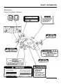
Safety Decals
Replace immediately if damaged.
IMPORTANT
FILL GEAR BOX TO CENTER
LINE OF HORIZONTAL SHAFT.
USE SAE 90 GEAR LUBE.
ALLOW TIME FOR OIL TO
FLOW THRU BEARINGS.
THEN RECHECK.
OF OPERATION
TO AVOID SERIOUS INJURY OR DEATH!
READ OPERATOR'S MANUALS & FOLLOW
ALL SAFETY PRECAUTIONS.
(CONTACT DEALER FOR MANUALS)
KEEP SHIELDS AND GUARDS IN PLACE
KEEP CLEAR OF DRIVES AND BELTS.
LOWER IMPLEMENT, STOP ENGINE AND
REMOVE KEY BEFORE DISMOUNTING.
CLEAR MOWING AREA OF DEBRIS.
DO NOT OPERATE MOWER IN VICINITY
OF OTHER PERSONS. NO RIDERS.
KNOW HOW TO STOP TRACTOR AND
EQUIPMENT QUICKLY IN AN EMERGENCY.
BLOCK UP IMPLEMENT AND HEMOVE
KEY BEFORE WORKING UNDERNEATH.
ALLOW NO CHILDREN OR UNQUALIFIED
PERSONS TO RUN EOUIPMENT.
BE CAREFUL ON UNEVEN TERRAIN.
DECREASE SPEED WHEN TURNING.
DO NOT OPERATE IN TRANSPORT
POSITION.
".
...
•
I
PTO SPEED MUST NOT
EXCEED 2400 RPM.
LOCK DRIVELINE ON
TRACTOR PTO.
A LOOSE DRlVELlNE OR A
HIGHER PTO RPM CAN
CAUSE PERSONAL INJURY
AND EQUIPMENT FAILURE.
7
SET-UP AND ASSEMBLY
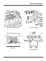
UNPACKING AND CHECKING PARTS
DEALER SET-UP INSTRUCTIONS
Assembly of this mower is the responsibility of the The mower assembly kit contains the following
parts:
dealer. The mower should be delivered to the
Mower deck with rear linkage installed
owner completely assembled, lubricated and
Lift plate assembly
adjusted for normal mowing conditions.
. Box containing lift linkage and hardware
Using these instructions, set mower up as reUnbolt the mower deck, and the lift plate assembly
ceived from the factory. Complete Check Lists on
and cut the packing straps holding down the rear
Page 10 when set-up is complete.
linkage and mower driie shaft. Packing list is
You may install the MM60 mower with the FL6555 contained in both the crate holding the mower,
and in the parts box in the crate. Before assemsub frame installed. The front loader must be
bling check for missing or damaged parts.
removed from the sub frame. If you also have a
BH6575 Back Hoe, both the back hoe and its sub
frame must be removed. The adjustment of the lift
rod is different from the standard installation.
These differences are explained in the appropriate
sections. Follow these procedures to avoid
damage to deck and linkage.
The mower is shipped partially assembled.
Assembly will be easier if components are aligned
and loosely assembled before tightening hardware. Recommended torque values for hardware,
are included in the assembly instructions.
Select a suitable working area. Open parts boxes
and lay out parts and hardware to make location
easy. Refer to illustrations, accompanying text,
parts lists and exploded view drawings.
For all pins, shafts and other bearing surfaces,
lubricate bearing area with a lithium based grease
of #2 consistency with a MOLY (molybdenum
disulfide) additive before installing. The manual
will also indicate when grease is necessary.
Always wear relatively tight and
belted clothing to avoid entanglement in
moving parts. Wear sturdy, rough-soled
work shoes and protective equipment for
eyes, hands, hearing and head.
Before working underneath, raise mower,
install transport lock and block mower
securely. Hydraulic system leak down and
failure of mechanical or hydraulic system
can cause equipment to drop.
Keep all persons away from operator
control area while performing adjustments, service or maintenance.
8
SET-UP AND ASSEMBLY
Mower Assembly Kit in Crate
Parts in Burlap Bag
/
Parts Box
Parts in Parts Box
9
SET-UP AND ASSEMBLY
Pre-Delivery Check List
(Dealer Responsibility)
Delivery Check List
(Dealer Responsibility)
1. Inspect the mower thoroughly after assembly to
ensure it is set up properly before delivering it to
the customer. The following check lists are a
reminder of points to inspect. Check off each
item as it is found satisfactory or after proper
adjustment is made.
1. Check mower attitude and belt alignment.
3. Show customer how to make adjustments.
2. Check all bolts to be sure they are correctly
torqued.
4. Explain importance of lubrication to customer
and point out lubrication points on mower.
3. Check that all linchpins are properly installed.
5. Point out safety features, shielding and options.
4. Lubricate all grease fittings; check to make sure
a small amount of grease comes out of seal.
6. Present the Operator's Manual, and ask customer to become familiar with all sections.
5. Check that gearbox is serviced and that vent
plug is properly installed and seals are not leaking.
7. Explain to customer that when mower is transported on a road or highway, safety devices
should be used for adequate warning to
operators of other vehicles.
6. Check that blades have been properly installed.
2. Check that mower lift is properly adjusted. (See
Assembly instructions.)
SET-UP AND ASSEMBLY
MOUNTING MOWER LIFT SYSTEM
Install with the tractor on level ground.
Lock the parking brake, set the transmission lever
in "N" (Neutral) and the PTO clutch lever in the
"OFF" position. Set Lift Control lever to "DOWN"
and turn Lowering Speed Control knob fully
counter-clockwise ("FAST"). This allows you to pull
the rear lift arms down by hand and makes assembly easier.
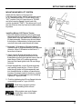
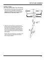
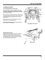
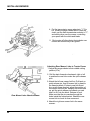
Installing Mower Lift Plate to Tractor
1. Remove drawbar assembly; this is bolted onto
the transmission housing below the Rear PTO.
Retain bolts, nuts and spacers for installation of
lift plate assembly. Remove any dirt and debris
from bottom of transmission housing and make
sure bolt holes and screw threads are clean.
2. Assemble Y-lift bracket to lift plate assembly.
Raised flange on lift plate assembly will face rear
of tractor. Insert Y-lift bracket so that fork of Y
faces front of tractor.
3. Attach mower lift plate assembly to tractor,
passing the two projecting stud bolts on the
transmission housing through the holes in the lift
plate flange. Slide on 2 spacers previously
removed and hand tighten both 26 mm flange
locknuts.
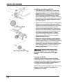
4. Reach beneath the mower lift plate assembly
and carefully insert the four 12 mm x 32 mm
bolts through holes in lift plate assembly and
into threaded holes on bottom of transmission
housing. Housing is made of aluminum, so start
bolts by hand to guard against cross threading.
Tighten to 7 kg-m (50 ft-lb).
5. Finish by tightening two 26 mm flange locknuts
on projecting studs to 7 kg-m (50 ft-lb).
Mower Lift Plate
Wear heavy gloves to protect
your hands when installing lift link kit and
mower deck.
Lifting system can crush fingers
and hands, so keep them clear of links and
lift arms when operating.
11
SET-UP AND ASSEMBLY
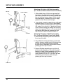
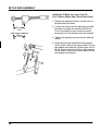
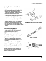
Lift Link
Attaching Lift Link to Lift Plate Assembly
(For Tractors Without Rear Three Point Hitch)
Lower Link Shaft
\
1. Slide middle hole in lift link onto greased left
hand lower link shaft which comes installed on
the tractor. Install lift link so that it is vertical and
the end with two holes is down. Lift link should
face rearward as illustrated. Be sure to apply
grease to shaft. Secure with linchpin.
2. Use a block of wood to raise left arm of lift plate
assembly about 150 mm (6 in) to make attaching the Y-bracket and the bottom hole of the lift
link easier. Line up hole in Y-bracket with lower
hole in lift link moving arm and lift link until they
align. Insert greased 22 mm x 76 mm clevis pin
and secure with cotter pin, passing pin from
top to bottom. Head on clevis pin faces in.
Y- bracket
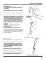
Attaching Lift Link to Lift Plate Assembly
(For Tractors With Rear Three Point Hitch)
1. Remove left hand three point hitch lower link
from lower link shaft.
2. Mount lift link and-lower link back on lower link
shaft by lining up middle hole in lift link and hole
in lower link. Pass greased lower link shaft
through both as illustrated. Secure with linchpin,
passing pin from top to bottom.
3. Support lift plate assembly arms on block of
wood as described above. Move lift link and Ybracket on lower lift plate assembly until hole in
Y-bracket and bottom hole in lift link line up.
Insert greased 22 mm x 57 mm clevis pin with
head facing in and secure with cotter pin,
passing pin from top to bottom.
Lower Link
12
SET-UP AND ASSEMBLY
Installing Lift Rods
(For Tractors Without Rear Three Point Hitch)
1. Adjust the lift rod to 365 mm (14.4 in) measured
from eye to eye as illustrated. Adjustment is
made by turning barrel of rod, then secured by
tightening nut. Be sure that an equal length of
threads shows on either end ,of barrel.
I
----c'I
I
I
I
Y
365 mm
14.4 in.
(with loader subframe)
375 mm
I
I
y
I.
I
y
14.8 in.
2. Slide eye of lift rod over pin on tractor lift arm.
Position clevis of lift rod between brackets on lift
link. Note that outside leg of lift rod goes outside of lift link as illustrated. Install with greased
22 x 76 mm clevis pin with head on left side as
shown. Secure both ends with 22 mm washers
and linchpins.
NOTE: The eye of the lift rod is not straight. The
curve should point to the inside of the tractor
when properly installed.
13
SET-UP AND ASSEMBLY
Installing Lift Rods on Lower Link Lift
(For Tractors With a Rear Three Point Hitch)
1. Replace the existing left hitch rod with the unit
provided with the mower.
I
I
I
I
‘y85 mm 7
3.4 in.
(with loader subframe)
100mm ;
4.0 in. -y
2. Loosen the locknut and the adjusting nuts and
turn them to position the bracket hole 85 mm
(3.4 in) from the lift rod eye (center-to-center
measurement). The bracket must face forward.
3. Tighten the adjusting nuts and secure with the
locknut.
4. Couple lift link chain and lift link with greased
16 mm lift pin. Head of pin faces inward. Secure
with washer and cotter pin. Attach upper end of
lift link chain to bracket on lift rod, with greased
16 mm lift pin. Head of pin faces inward. Secure
with washer and linchpin.
14
SET-UP AND ASSEMBLY
Adjusting Lift Rod
(For Tractors With and Without Rear Three
Point Hitch)
Follow this procedure if you do not have a loader
subframe installed.
Adjust the lift rod clearance by starting the engine,
and shifting the Lift Control lever to "UP". Make
sure hands are clear of lift arms before starting.
Engine will not start unless operator is seated.
Raise until lift arm reaches top or until resistance is
encountered. If resistance is encountered, stop.
Turn Lowering Speed control fully clockwise to lock
arms up. Turn engine off. Grasp lift rods and
check them for slack. They should be able to slide
slightly on their pins. If there is no-slack in the lift
rods, increase clearance as illustrated.
arm should not
contact stopper
Lifting system can be seriously
damaged if arm presses against stop.
Adjusting Lift Rod
(Tractors With Rear Three Point Hitch)
To increase clearance turn bottom nut on adjuster
counterclockwise to loosen, slide down flange and
then snug top nut. To decrease clearance, slide
adjuster up as shown.
With Three Point
Adjusting Lift Rod
(Tractors Without Rear Three Point Hitch)
Turn the barrel of the lift rod by the projecting pins
to shorten or lengthen the rod. Move adjuster as
required. The projecting pins must point side to
side (transversely) when you are finished. If they
don't, turn the barrel in the direction to increase
clearance until they do.
Restart engine, move Lift Selector lever to "UP.
When lift arms reach top position, stop engine,
apply brakes and re-check clearance. Keep hands
and fingers clear of lift system when operating to
avoid injury. There should be slack in the linkage. If
there is not, readjust as necessary. Tighten locknuts after adjusting both types of lift rods.
Without Three Point Hitch
15
SET-UP AND ASSEMBLY
Subassembling Front Link Brackets
Assemble by compressing the front spring and
inserting it in the front bracket slot. Pass greased
front quick release pin through hole in the front
bracket and spring. Pull back spring slightly to
uncover hole in quick release pin. Use hammer to
tap in spring pin until it is equidistant from both
sides of quick release pin.
NOTE: Hold back bottom of spring so that pin
clears it.
Assemble both right and left brackets.
Front Link Bracket
Mounting Front Link Bracket to Tractor
1. From bottom, slip the assembled front mounting bracket up onto the front frame rails.
2. Insert 8 flange bolts 12 mm x 30 mm. Tighten all
to 6 kg-m (43 ft-lb).
NOTE: With pins correctly installed, they will
face rearward and downward when front link
bracket is installed on the tractor.
Front Link Bracket
Assembling Rear Link Bracket
Insert the greased rear quick release pin in the
mounting bracket attached to the tractor frame. It
is located beneath the tractor along the mid-line
as illustrated. Pass the long arm of the quick
release pin through the lower hole in the bracket
and the spring. Compress the spring and slide
washer over hole in arm. Secure with split pin,
spreading legs of split pin. Assemble both right
and left brackets.
Rear Link Brackef
16
INSTALLING MOWER
ASSEMBLING MOWER
Checking Rear Mower Deck Links
Rear mower links will come installed. Check that
vibration in shipping has not shaken loose the two
clevis pins in brackets at rear of mower. They are
secured with linchpins.
Rear deck links should face forward, towards front
of mower, before driving tractor over mower. They
cannot be rotated forward after tractor is above
mower deck.
Mower driveline and U-joint should be on top of
stabilizer bar, not caught below it.
Be sure the left rear deck link is installed with the
side marked "UP" facing top.
Rear Mower Deck Links
Installing Deck Hooks
Right and left mower deck hooks are installed on
brackets in the front center of the deck. See
position as indicated. Screw mower deck hook
into adjustable pin. Insert pin into slot in bracket.
Secure with washer and linchpin.
/
f
I'
Deck Hooks
INSTALLING MOWER
Installing and Adjusting Wheels
1. Pull release pin on wheel yoke so that wheel
arm can be raised to insert wheel. Assemble
wheel by inserting 1/2 x 5 in. sleeve through
wheel. Place 1/2 in. washer on 1/2 x 5 in. bolt
and insert though yoke and sleeve in wheel.
Secure with flanged locknut. Tighten locknut so
that sides of bracket touch wheel sleeve without
binding. Do not over-tighten. Repeat for other
front caster wheel.
'
<
\
Front Caster Wheel
2. Assemble the rear gauge wheels so that grease
fittings are to the inside for lubrication access.
Raise rear of mower deck with lever or jack and
insert wood block beneath mower deck to
support it while installing wheels. Insert sleeve
through wheel. Place washer on bolt and insert
through sleeve in wheel and rear gauge wheel
arm. Secure with flanged locknut. Tighten
locknut so that sides of bracket touch wheel
sleeve without binding. Do not over-tighten.
Repeat for opposite side.
3. Raise front and rear wheels to middle position,
insert pin in center hole of adjustment bracket.
Cutting height will be 2.75 in. Level the mower to
assure proper cut. Mower also needs slight
forward tilt. If adjusting wheels and blade height
after installing mower on tractor, make sure
engine is off and key is removed before
looking under mower.
Support mower deck solidly
while installing wheels. Keep fingers and
feet clear of deck until deck is firmly supported.
!
Rear Gauge Wheels \'@
a-
Leveling the Mower
Level the mower to assure proper cut. Mower
needs slight (3/8 in) forward tilt. If you are adjusting wheels and blade height after installing mower
on tractor, make sure engine is off and key removed before looking under mower.
NOTE: Before measuring blade height, turn mower
blades so that the right and left blades point
towards front of mower.
INSTALLING MOWER
NOTE: Tool is available (see illustration) for ease
of measurement.
1. To level mower from side to side, measure
distance from front blade tip to ground. For left
and right blades, measurements should be
within 5 mm (1/4 in) of each other. Move
washers as necessary to raise the low corner.
To add washers, raise mower deck until wheels
clear ground by about 5 in.
2. Place wood block or floor jack under edge of
mower to hold it while wheel is removed. Drive
out split pin from lower caster wheel to remove
caster wheel shaft. Move washers to the bottom
part of caster wheel shaft as illustrated . Each
washer changes height by 3 mm (about 1/8 in).
Mower Leveling Tool
HONDA Part No.
07JPJ-75001OA
3. Re-attach wheel, let mower down to rest on
wheels, and re-measure. Repeat the adjustment
until the difference between blade heights is
approximately 5 mm (1/4 in). Do not replace
split pin until after adjusting forward tilt.
4. Adjust forward tilt by measuring from front and
rear of blades to ground. The front of the blades
should be about 10 mm (3/8 in) lower than the
rear of the blades. If difference is less than 5
mm (1/4 in) take washers from bottom of gauge
wheel shaft and move to top. If difference in
blade tip to ground measurements is more than
15 mm (1/2 in), take washers from top of
gauge wheel shaft and move to bottom as
illustrated. Move equal numbers of washers for
both left and right sides. Replace split pins.
W
Caster Wheels
Installing Front Anti-Scalping Roller
1. Insert 1/2 x 5 in sleeve in wheel. Place 1/2 x 5 in.
bolt through brackets for front anti-scalping
roller and through sleeve as illustrated.
2. Secure with 1/2 in flanged hex locknut. Tighten
locknut so that sides of bracket touch wheel
sleeve without binding.
W
Front Anti-Scalping Roller
19
INSTALLING MOWER
Installing Discharge Chute Cover
1. Using 3/8 x 1 in. carriage bolts, insert bolts from
under mower deck, passing through holes in
deck and discharge chute.
2. Secure with 3/8 in. flange locknuts.
Discharge Chute
Y
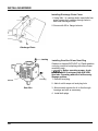
Level Plug
Gearbox
1
Installing Gear Box Oil and Vent Plug
Gearbox is shipped WITHOUT oil. Plastic gearbox
vent plug comes in burlap bag with other mower
assembly parts.
-1
Before operating mower, check
gearbox and fill if necessary with SAE 9OW
gear lube. Operating without oil will severely
damage gearbox.
1. Remove level plug.
2. Add oil until it seeps out level plug hole.
Gear Box
3. Allow several minutes for oil to flow through
bearings and refill as necessary.
4. Install both plugs
20
INSTALLING MOWER
Attaching Front Mower Links To Mower
1. Screw the adjustable plate link onto the right
and left front mower links. Adjust the plate link
as shown in illustration, so that the straight line
length is 450 mm (17.75 in). Face the plate link
to the outside as shown and insert into the
projecting brackets on the mower deck .
2. Install both right and left links. Secure with 16
mm greased clevis pin inserting pin from outside. Insert linchpin to lock.
Front Mower Links
INSTALLING MOWER TO TRACTOR
1. Adjust gauge wheels to lowest cutting position.
2. Chock right and left front wheels as shown.
3. Start the tractor and keep engine at low idling
speed. Set the lift control lever to the "UP"
position and keep the lift arm up.
Drive front wheels over the flat
area of the pulley covers only! Avoid running over gear box, drive shaft and rear links
to prevent damaging them.
Front Wheels Chocked
21
~~
INSTALLING MOWER
4. Put the transmission range selector in "1." For
A-4 models, engage 4-wheel drive. Press the
clutch, put the main transmission selector in "1",
and slowly drive over the mower, controlling
your speed with the clutch.and brake.
5. Shut engine off after driving front wheels over
mower and remove key from ignition.
Attaching Rear Mower Links to Tractor Frame
1. Adjust the gauge wheels to their middle cutting
position (2 in).
2. Roll the deck forward or backward, right or left
to position the rear links under the quick-release
pins.
Rear Mower Links Attach to Mower
3. Attach the left rear mower link first. Pull back on
quick release pin, then lift mower link by hand to
the frame brackets. If holes in rear link do not
line up with frame bracket, adjust the position of
the mower until they do. Keeping the holes lined
up, pull the quick release pin towards you and
turn it to fit it into the holes. Release to lock.
Make sure that the pin reaches through the
holes inside the frame bracket. Shake the rear
mower link to check for free movement.
4. Attach the right rear mower link in the same.
manner.
22
INSTALLING MOWER
Attaching Front Mower Links to Front
Bracket
1. Pull back on quick release pin in right or left
front link bracket and twist until the spring pin
catches in slot. Raise front mower link to
bracket and line up holes. Looking from inside
the bracket, check alignment of holes.
2. If the holes in the bracket and the front link do
not line up, twist front deck link by screwing it
in or out to adjust length. If link is too long, turn
clockwise to shorten. If link is too short, turn
counterclockwise. to lengthen. Adjust both links
an equal number of turns.
3. When the holes line up, pull quick release pin
towards you and turn to release spring pin
from slot. Make sure that quick release pin is
fully inserted through the holes inside the frame
bracket.
Front Mower Links Attach to Front Bracket
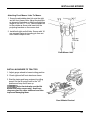
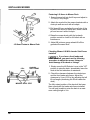
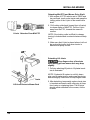
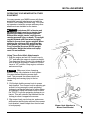
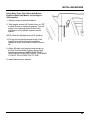
Attaching Driveline to Mid-PTO
1. Engine should be OFF with key removed
before attaching U-joint to Mid-PTO.
NOTE: The mower drive shaft is a 2-piece assembly. The inner shaft can be removed from the
outer shaft. They fit together in only one way. A
red paint dot on each section marks the blind
spines which must be aligned.
2. Set the PTO Selector to the REAR position
before attaching (this allows the Mid-PTO to
turn freely).
3. Line up U-joint with shaft of the Mid-PTO.
Splines will engage when correctly lined up.
Pull back spring loaded locking collar on Ujoint (towards the mower deck) as illustrated
to insert U-joint into Mid-PTO. Slip U-joint into
shaft until a click is heard.
Once the connection is made, shake the driie
shaft to be certain that the locking collar is forward and completely locked.
U-joint Attaches to Mid-PTO
23
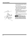
INSTALLING MOWER
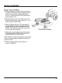
Fastening Lift Arms to Mower Deck
1. Screw the eye bolt into the lift eye and adjust to
137 mm (5.4 in) length.
2. Attach the eye bolt to the mower brackets with a
clevis pin and secure it with a linchpin.
3. Pull down lift arm and align the oval hole of the
lift joint in the clevis of the lift arm, insert a clevis
pin and secure it with a linchpin.
4. Raise the mower slowly with the hydraulic
position control to check for full travel with no
interference.
Lift Arms Fasten to Mower Deck
5. Adjust lift joints so gauge wheels lift off the
ground at the same time.
Checking Mower Lift With Loader Sub-Frame
Installed
If you have a front loader sub
frame installed, you must use the following
procedure to adjust the mower linkage to
avoid damage to the deck or linkage.
1-
0.2in
LOADER
SUB FRAME
1. Slowly move the Lift Selector Lever to the "UP"
position to raise the deck. Immediately lower the
deck at the first indication of resistance.
2. Check the clearance between the deck stops
and the front loader sub frame. Adjust the
clearance to 5 mm (0.20 in) by adjusting the left
lift rod length (shortening the lift rod raises the
deck).
MOWER DECK STOP
24
The fully raised position of the deck will be lower
than normal with the loader sub frame installed.
You will only be able to raise the deck to a maximum cutting height of 4 in.
INSTALLING MOWER
DETACHING MOWER FROM TRACTOR
I
Detaching Front Links
NOTE: If mower deck hook is engaged to hold
mower deck up, deck must be raised and hook
released before mower can be detached.
1. Pull locking pins on mower wheels and set
wheels so that mower is high as possible. This
will make removing quick release pins on links
easier.
2. Pull right and left front quick release pins by
pulling back on pin and turning until spring pin
catches and holds in slot in front link bracket.
Hold front link and lower it to ground. Repeat for
other side.
Front Mower Links Detach From Tractor
Mower deck will descend when
front links are released. Keep fingers and
feet from being caught below the mower to
avoid injury.
Detaching Rear Links
1. Pull locking pin on left rear link and draw it
towards you to remove. If rear link cannot be
detached easily, shake the mower back and
forth with foot, until rear link comes loose.
NOTE: Be careful not to get your fingers caught
between the rear arms of the lift plate assembly
and the mower deck. Arms come down when pin
is detached.
Rear Mower Links Detach From Tractor
25
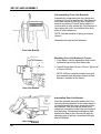
INSTALLING MOWER
Detaching Mid-PTO and Mower Drive Shaft
1.With engine off, PTO selector set to "REAR" and
key removed, reach under tractor and grasp the
locking collar of the U-joint of the mower drive
shaft.
2. Pull locking collar back (toward front of tractor)
to release spline of Mid-PTO. Pull the U-joint
away from the PTO, towards the mower to
remove.
U-Joint Detaches From Mid-PTO
NOTE: If the locking collar is difficult to release,
turning it clockwise and counterclockwise will help
free it.
3. Make sure that U-joint is placed where it will not
be crushed by tractor tires when tractor is
backed over pulley covers.
Ufl Arm
Detaching Lift Joints
Keep fingers clear of brackets
when pulling pins as mower deck may drop
slightly.
!
1 -
1. Pull pins attaching lift joints to. lift plates brackets as illustrated.
NOTE: If hydraulic lift system is not fully down,
pins may be under tension and mower deck may
descend slightly. Make sure to keep fingers clear.
Lift Arms Fasten to Mower Deck
26
2. After detaching, temporarily replace clevis pins
in brackets and secure with cotter pins to keep
from losing or misplacing them. The lift joints
should remain attached to the mower, not the
lift arms.
INSTALLING MOWER
Moving Tractor Off Mower
1. Before detaching, chock front and rear wheels
of mower as illustrated. Place triangular piece of
wood in front of mower, aligned with pulley
covers, to avoid having the mower slide as the
tractor climbs over it.
2. Start the engine, move Lift Control Lever "UP,
place the transmission range selector in "1" (A-4
models, select 4-wheel drive).
3. Move Lift Sector Lever to "UP" and raise lift
arms to maximum position. Keeping engine at
low idle speed, set main transmission to "REVERSE" (on 4-wheel drive models, move selector to 4-wheel drive position).
Front Wheels Chocked
4. Making fine speed adjustments with accelerator, back the tractor off the mower, with front
wheels passing over pulley covers.
NOTE: Make sure that the wheels pass over pulley
covers to avoid damage to gear box, rear link or
puncture of tires.
5. Switch off engine after moving tractor off
mower. Set brakes.
27
OPERATION
Safety is a primary concern in the design
and manufacture of our products. Unfortunately, our efforts to provide safe equipment
can be wiped out by a single careless act of
an operator.
In addition to the design and configuration
of equipment, hazard control and accident
prevention are dependent upon the awareness, concern, prudence and proper training
of personnel involved in the operation,
transport, maintenance and storage of
equipment.
The operator is responsible for the safe operation
of this mower. The operator must be properly
trained and qualified. Operators should be familiar
with the mower and tractor and all safety practices
before starting operation. Read the safety information on pages 4-7.
This mower is designed for lawn or grass mowing.
It is not designed for rough conditions or heavy
weed mowing. It is equipped with suction type
blades for best results in lawn mowing.
Recommended mowing speed for most conditions is from two to five mph.
It has been said 'the best safety device is an
informed, careful operator'. We ask you to
be that kind of an operator.
• Do not allow children or unqualified persons to operate equipment.
Keep bystanders away from equipment
while it is in operation.
Before working underneath, raise mower,
install transport lock and block mower
securely. Hydraulic system leak down and
failure of mechanical or hydraulic system
can cause equipment to drop.
Keep all persons away from operator
control area while performing adjustments, service or maintenance.
Operate tractor mid-PTO at no more than
2400 RPM (maximum governed engine
RPM).
Make sure mower driveline spring-activated locking collar slides freely and the
balls are seated in mid-PTO shaft groove.
Stop mower and tractor immediately upon
striking an obstruction. Turn off engine,
remove key, inspect and repair any damage before resuming operation.
Always wear relatively tight and belted
clothing to avoid entanglement in moving
parts. Wear sturdy, rough-soled work
shoes and protective equipment for eyes,
hands, hearing and head.
28
OPERATION
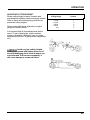
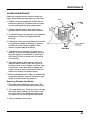
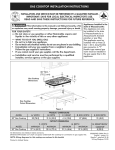
ADJUSTING CUTTING HEIGHT
Mower cutting height is raised, lowered, and
maintained by adjusting caster and gauge wheels.
Refer to figure and accompanying chart for approximate cutting heights.
Raise mower with tractor hydraulics to adjust
gauge and caster wheels.
Approximate
Cutting Height
Position
1-1/2 in.
2-1/8 in.
2-3/4 in.
3-3/8 in.
4 in.
1
2
3
4
5
It is important that all three adjustments be the
same. To set cutting height, match numbers
shown in illustration. (Example: hole 2 in caster
adjustment with hole 2 in gauge wheel adjustment,
etc.)
Avoid very low cutting heights.
Striking the ground with blades gives one of
the most damaging shock loads a mower can
encounter and, if this occurs repeatedly, it
will cause damage to mower and drive.
29
OPERATION
PRE-OPERATION CHECK LIST
Operate tractor mid-PTO at no more than
2400 RPM (maximum governed engine
RPM).
You may not be able to stop the tractor
safely if the clutch or brake pedal mechanisms are improperly adjusted, allowing
them to contact mower components.
When the mower lift stops are installed as
instructed in this manual, properly adjusted clutch and brake pedal mechanisms will not contact mower components. You should frequently check that
the tractor clutch and brake pedal mechanisms are in adjustment.
If the clutch or brake pedal mechanisms
can contact mower components, do not
operate until properly adjusted.
1. Review and follow safety rules on pages 4-7.
2. Do not operate mower unless belt shield and
discharge chute are in place and securely
fastened.
3. Check that mower is properly and securely
attached to tractor.
4. Check to ensure blades are sharp, secure and
properly installed. See Blade Condition on
Page 38.
5. Check that all hardware is properly installed
and secured.
6. Check to ensure spindles and caster wheels
are lubricated .
7. When attaching U-joint to tractor mid-PTO
shaft, it is important that the spring-activated
locking collar slides freely and the balls are
seated in groove on mid-PTO shaft.
8. Check mower cutting height and attitude
adjustment. See Adjusting Cutting Height on
Page 29.
9. Raise mower carefully and check to be sure it
does not come in contact with hydraulic lines.
10. Remove grass and other foreign material from
the top of the deck.
30
Mower vibration tends to loosen
bolts during operation. All hardware should
be checked regularly to maintain proper
torque. It is a good practice to check mower
before each operation to ensure all bolts are
secure.
Power for operating mower is supplied by tractor
mid-PTO. Do not exceed tractor manufacturer's
rated mid-PTO speed of 2400 RPM (maximum
governed engine RPM). Know how to stop tractor
and mower quickly in case of an emergency.
Should mower become plugged, causing belt to
slip for over two seconds, maneuver equipment
into a previously cut area and allow mower to clear
accumulated material. Continue running at least
two minutes, allowing pulleys to cool. Stopping the
mower with belt in contact with a very hot pulley
will bake and ruin belt.
Stop mower and tractor immediately upon striking an obstruction. Turn off
engine, remove key, inspect and repair any
damage before resuming operation.
OPERATION
Tips
OPERATING TECHNIQUE
Proper ground speed will depend upon the terrain, Extremely tall material should be cut twice. Set
mower at a higher cutting height for the first pass.
the height, type and density of material to be cut.
Then cut at desired height at 90° to the first pass.
Normally, ground speed will range from two to five
Remember, sharp blades produce cleaner cuts
mph. Tall dense material should be cut at a low
speed; thin medium-height material can be cut at and require less power.
a faster ground speed.
Analyze area to be cut to determine the best
procedure. Consider height and type of grass and
Always operate tractor mid-PTO at maximum
terrain type: hilly, level or rough.
governed engine RPM. This is necessary to
maintain proper blade speed and produce a clean
Plan your mowing pattern to travel straight forward
cut.
whenever possible. Mow with uncut grass to the
left. This will distribute the clippings over the cut
Under certain conditions, tractor tires may roll
some grass down and prevent it from being cut at area. Discharging clippings over uncut grass will
cause a build-up and may prevent uniform cutting.
the same height as the surrounding area. When
this occurs, reduce your ground speed, but
D .
Do not operate mower unless
maintain maximum engine RPM. The lower ground
speed will permit grass to at least partially redischarge chute and belt shields are inbound.
stalled.
Under some conditions, grass will not rebound
enough to be cut evenly. In general, lower cutting
heights give a more even cut with less tendency to
leave tire tracks. However, it is better to cut grass
frequently rather than too short. Short grass
deteriorates rapidly in hot weather and invites
weed growth during growing seasons. Follow
local recommendations for the suitable cutting
height in your area.
When operating the mower, move the Lift Control
Lever to the "DOWN" position.
This will allow the mower to follow ground contours.
31
OPERATION
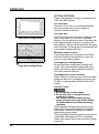
CUTTING PATTERNS
These cutting patterns are only recommended for
a flat, level lawn surface.
In a small area
First make 2 or 3 turns in a clockwise direction.
then turn around and continue cutting in a
counter-closckwise direction.
Small Area Cuffing Pattern
In a large area
The first round of cuts is the key to making a neat
finish. First, make 2 or 3 turns in a clockwise
direction. As you reach the center of the area, turn
to the right and begin cutting in a counter-clockwise direction until you have finished the the upper
half of the area. Cut the grass in the remaining half
in a counter-clockwise dire'ction.
Mowing unsquare areas
If your mowing area is not square or four-sided,
divide the area into several blocks so you can
mow in a neat mowing pattern.
t Large Area Cutting Pattern
Overlapping on straightaways
Be sure that each mowing lane overlaps sufficiently. The recommended overlap width is between 4-6 inches or approximately the width of
one of the mower's front tires.
Overlapping in curves and turns
When cutting in curves and turns, shift to a slower
speed and be sure to overlap the previous cut by
20-50% or approximately half the width of the
mower.
Uneven Terrain
Do not operate on steep slopes.
Do not stop, start or change directions
suddenly on slopes.
Use extreme care and reduce ground
speed on slopes and rough terrain. Watch
for hidden hazards on the terrain during
operation.
Pass diagonally through sharp dips and avoid
sharp drops to prevent "hanging up" the tractor
and mower. Practice will improve your skills in
maneuvering rough terrain.
Take all possible precautions when leaving tractor
unattended: disengage mid-PTO; set parking
brake, stop engine, remove key and lower mower
to ground.
32
INSTALLING MOWER
OPERATING YOUR MOWER WITH OTHER
EQUIPMENT
You may operate your MM60 mower with threepoint hitch mounted attachments and with the
FL6555 Front Loader sub frame only. You must
not operate or install the mower while any other
attachments are installed on the tractor.
A minimum 20% of tractor and
equipment weight must be on tractor front
wheels with mower in transport position.
Without this weight, tractor could tip over
causing personal injury or death. The weight
may be attained with front wheel weights,
ballast in tires or front tractor weights. When
attaining the minimum 20% weight on the
front wheels, you must not exceed the Roll
Over Protection Structure (ROPS) weight
certification. Weigh the tractor and equipment. Do not estimate.
Using Three-Point Hitch Attachments
1. Start the engine and set Lift Control Lever to
“UP” and raise the mower to maximum height.
Turn Lowering Speed Control fully clockwise to
lock lift arms in up position. Leave Lift Control
Lever in “UP” position. Stop engine, set brake
and remove keys.
I’
I! CAUTION Make sure to turn Lowering
Speed Control fully clockwise to lock hydraulic system before attaching mower deck
hook. This prevents the mower deck from
descending and causing injury to feet or
hands.
I
2. Pull linchpin holding mower hook to mower
hook bracket. Turn mower hook in adjusting pin
so that it is long enough to reach projecting
lockup pin on bracket attached to tractor frame
as illustrated. Adjust the mower hook so that it
fits TIGHTLY over the projecting lockup pin on
tractor. This will minimize the backlash on the
lockup pin when it supports the mower.
3. Slip mower hook over lockup pin, and secure
with washer and linchpin removed from mower
hook bracket. Insert linchpin from front to back
to lock properly.
Mower Hook Attaches to
Mower Hook Bracket
33
INSTALLING MOWER
4. Place other attachment on Rear Three Point
Hitch . Mower deck will be held out of the way
by mower deck hook.
NOTE: The mower deck will be raised a small
amount when Lift Control Lever in fully “UP”
position. This is due to the play in the mower
deck hook and will not affect the operation of
the Rear Three Point Hitch or attachment.
Unlocking Mower Hook
1. Start engine and set Lift Control Lever on “UP”
to raise lift arms to maximum position. Turn off
engine, turn Lowering Speed Control fully
clockwise to lock hydraulic system and set
brakes.
2. Remove clevis pin and use tool to pull mower
hook off of lockup pin. Use caution since hook
may be under pressure.
!
Mower hook may be under
tension. Set Lift Control Lever to “UP” and
raise arm to take tension off hook before
detaching. Turn engine off so that lift arm
cannot move. Wear heavy gloves and keep
fingers away from lift arms to avoid injury.
.-
34
INSTALLING MOWER
Using Rear Three Point Hitch with Mower
Detached While the Mower Lift Linkage is
Still Installed
1. Detach mower as described below.
2. Start engine and set Lift Control Lever on "UP"
to raise lift arms to maximum position. Turn off
engine, turn Lowering Speed Control fully
clockwise to lock hydraulic system and set
brakes.
NOTE: Block the lift plate to its full UP position.
3. Pull pin from projecting bracket at top of left
hand lift rod, and remove as illustrated to
release lift chain. Hold chain so that it does not
fall.
4. Attach lift chain to projecting chain rest pin on
the Roll Over Protection System. Secure with
washer and cotter pin. MAKE SURE TO RETAIN CLEVIS PIN IN SAFE PLACE TO BE ABLE
TO RE-ATTACH CHAIN TO LIFT ROD.
5. Install attachment as needed.
35
MAINTENANCE
OWNER SERVICE
The information in this section is written for operators who possess basic mechanical skills. Should
you need help, your dealer has trained service
technicians available. For your protection, read
and follow all safety information in this manual.
Before working underneath, raise mower,
install transport lock and block mower
securely. Hydraulic system leak down and
failure of mechanical or hydraulic system
can cause equipment to drop.
Keep all persons away from operator
control area while performing adjustments, service or maintenance.
Lower mower to ground or block securely,
turn tractor engine off, remove key and
disconnect mower driveline from tractor
PTO before performing any service or
maintenance.
CAUTION
b4
-qAlways wear relatively tight and
belted clothing to avoid entanglement in
moving parts. Wear sturdy, rough-soled
work shoes and protective equipment for
eyes, hands, hearing and head.
36
MAINTENANCE
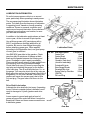
LUBRICATION INFORMATION
Do not let excess grease collect on or around
parts, particularly when operating in sandy areas.
2
The accompanying illustration shows lubrication
points. The chart gives the frequency of lubrication
in operating hours, based on normal operating
conditions. Severe or unusual conditions may
require more frequent lubrication. Some reference
numbers have more than one location; be sure
you lubricate all locations.
In addition to the lubrication points shown, at least
once a year, oil the six mower lift pivot points.
Use a lithium grease of #2 consistency with a
MOLY (molybdenum disulfide) additive for all
locations. Be sure to clean fittings thoroughly
before attaching grease gun. When applied
according to the lubrication chart, one good pump
of most guns is sufficient.
Use SAE 90W gear lube in the gearbox. Check
gear box daily for evidence of leakage at both
seals and the gasket between the housing and
cover. If leakage is noted, repair immediately.
There may be a small amount of lube emitted from
the vent plug; this is not considered leakage.
Check lube level every 50 hours by removing the
vent plug and checking the gauge on the bottom
of the vent plug. The oil level should show 1 in. on
the gauge. You may also check the oil by using an
Allen wrench to remove the level plug in the front of
the gearbox. Do not over lubricate. Over-filling the
gearbox will cause the excess gear lube to blow
out vent plug. The gear lube could then ruin the
belt.
Lubrication Points
Ref. No.
1.
2. .
3.
4.
5.
6.
7.
8.
9.
Item Description
Frequency
Caster Pivot
8 hrs
Caster Wheel
8 hrs
Blade Spindles
24 hrs
Gearbox- Check level
50 hrs
(check for leaks daily)
Driveshaft U-joints
8 hrs
Rear Gauge Wheels
8 hrs
Driveshaft Slip Joint
8 hrs
Spring Take-up Pivot Arm
24 hrs
(30W Oil)
Oil Level Plug
50 hrs
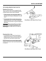
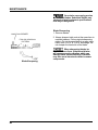
Drive Shaft Lubrication
Lubricate the drive shaft slip joint every 8 operating
hours. Failure to maintain proper lubrication could
result in damage to U-joints, gearbox and drive
shaft.
Lower mower to ground and apply a bead of
grease all around the male half where it meets the
female half. Raise and lower mower several times
to distribute grease.
Gearbox
Gear Box
37
MAINTENANCE
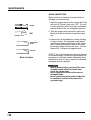
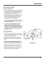
BLADE INSPECTION
Before each use, check each mower blade for
damage or abnormal wear.
.
NORMAL
1. Start the engine and raise the mower deck fully
with the Lift Control Lever set to "UP". Turn the
Lowering Speed Control knob fully clockwise to
prevent descent. Do not overtighten the knob.
2. Stop the engine and remove the ignition key.
Block deck with wood block to prevent lowering.
-=
EXCESSIVELY
WORN
3. Inspect each of the blades for cracks, bending
or signs of wear. The right and center blades
can be seen under the right side of the mower
deck. The left blade can be seen from under
the left front edge of the mower deck. Turn the
blades 180° to inspect the opposite side.
CRACKED
Blade Condition
NOTE: If any of the blades show signs of damage
or excessive wear, a more thorough inspection is
necessary. A dull blade can be sharpened, but a
blade that is worn out, bent, cracked or otherwise
damaged must be replaced.
Severe personal injury can result if a piece
of blade breaks off and is thrown from
under the mower deck.
Never operate the tractor with a worn or
damaged blade.
Never operate the tractor with a blade that
is cracked or notched at the base of its
upturned edge.
MAINTENANCE
~~
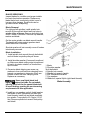
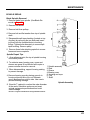
BLADE SERVICING
Inspect blades for condition and proper installation each time before operation. Replace any
blade that is bent, excessively nicked, worn or
has any other damage. Small nicks can be
ground out when sharpening.
Blade Removal
For right and left spindles, install spindle lock
wrench (5) through belt shield and into holes in
spindle pulley as shown. Remove bolt which has
RIGHT HAND THREADS. Remove cup washers,
washer and blade.
On the center spindle use blade wrench handle.
The handle will rotate against gearbox stand
when blade bolt is removed.
Shoulder washer will not normally come off unless
intentionally removed.
Blade Installation
1. Install spindle lock wrench through belt shield
and into holes in spindle pulley as shown.
2. Install shoulder washer (if removed) small end
up. Make sure blade cutting edge is positioned
to lead in clockwise rotation, as viewed from
top of mower.
3. Excessive blade slipping can cause cup
washers to burn and lose their clamping force,
Inspect cup washers to determine if they are
burned or have lost their clamping force.
Replace as necessary.
Use a new Nylok blade bolt
when you replace the blade. Do not substitute any other bolt for the special blade bolt.
It is self-locking, meeting the non-loosening
requirements for this application.
1. Blade
2. Shoulder washer
3.Left belt shield
4. Spindle lock wrench
5. Spindle lock wrench handle
6. 5/8" Standard flat washer
7. Cup washers
8. Blade bolt, special Nylok (right hand threads)
Blade Assembly
4. Install two cup washers on bolt. Install washer
and blade on bolt. Remember bolt has right
hand threads; install bolt and blade assembly
into spindle. Torque bolt to 23.5 kg/m (170 ft/
Ibs). Remove spindle lock wrench from pulley
and shield.
39
MAINTENANCE
Your dealer can supply genuine
replacement blades. Substitute blades may
not meet original equipment specifications
and may be dangerous.
!
/
MAINTAIN CORNER
FOLLOW ORIGINAL
PATTERN
a
.
Blade Sharpening
1. Remove blades.
2. Always sharpen both ends at the same time to
maintain balance. Follow original sharpening
pattern. Do not sharpen blade to a razor edge.
Leave from 1/32 in. to 1/16 in. blunt edge. Do
not sharpen the back side of the blade.
1-
When sharpening blades be
sure to balance them. Unbalanced blades
will cause excessive vibration which can
damage blade spindle bearings. Vibration
may also cause structural cracks in mower
components.
Blade Sharpening
40
MAINTENANCE
REPLACING BLADE BELT
Removing Blade Belt
1. Remove right and left pulley covers (as viewed
from rear of mower). Right cover is held on by
two bolts and one nut, left cover by two bolts.
Retain bolts and nuts to replace cover.
2. Grasp belt with both hands on either side of the
rear center idler pulley (see illustration for
location). Pull back towards you to create
enough slack to slip belt off pulley.
3. Belt will now be quite slack and can easily be
removed from other pulleys, including tensioner
arm pulley (illustrated).
3. To remove belt from gearbox driven pulley,
remove the two bolts holding front of the
gearbox mount to mower deck, and loosen the
two bolts on the rear of the gearbox mount. Tip
the gearbox up and slip the belt off the gearbox
pulley and slide it underneath the gearbox to
completely remove.
sloner Arm Pulley
Installing Blade Belt
1. Remove the two bolts holding front of gearbox
mount to mower deck, and loosen the two rear
bolts (if not done previously).
2. Tilt gearbox up and slide belt underneath
gearbox. Fit into pulley V-grove and reinstall
bolts.
3. Fit belt over all except center rear idler pulley.
Make sure that belt goes behind pivot on
tensioner arm (belt makes a bend at this point).
Center Idler Pulley
v
Belt Assembly
4. Grasp belt with both hands, and pull back
towards you. Slip belt over center idler pulley.
5. Reinstall left and right pulley covers. Do not
operate without pulley covers installed.
41
MAINTENANCE
DEALER LEVEL MAINTENANCE
The information in this section is written for dealer
service personnel. The repair described herein
requires special skills and tools. If your shop is not
properly equipped or your mechanics are not
properly trained in this type of repair, you may be
time and money ahead to replace complete
assemblies.
Before working underneath, raise mower,
install transport lock and block mower
securely. Hydraulic system leak down and
failure of mechanical or hydraulic system
can cause equipment to drop.
• Keep all persons away from operator
control area while performing adjustments,
service or maintenance.
Lower mower to ground or block securely,
turn tractor engine off, remove key and
disconnect mower driveline from tractor
PTO before performing any service or
maintenance.
Always wear relatively tight and
belted clothing to avoid entanglement in
moving parts. Wear sturdy, rough-soled work
shoes and protective equipment for eyes,
hands, hearing and head.
mMake sure mower driveline
!
spring-activated locking collar slides freely
and the balls are seated in mid-PTO shaft
groove.
42
MAINTENANCE
SPINDLE REPAIR
Blade Spindle Removal
1. Remove blade from spindle. (See Blade Removal on Page 39.)
2. Remove belt shield.
3. Remove belt from pulleys.
4. Remove bolt and flat washer from top of spindle
shaft.
—1
5-
5. Disassemble split taper bushing (located on top
of pulley) by removing the two bolts and inserting them into the threaded holes in bushing
flange. Tighten bolts alternately to remove split
taper bushing. Remove pulley.
6. Remove three bolts attaching spindle to mower
frame and remove spindle.
Spindle Repair Tips
1. As a reference point, the top of spindle housing
is the short portion.
2. To minimize wear, bearing cups, cones and
sleeves are press fit to shaft and will require a
press or similar device for removal.
3. When disassembling, support housing casting
to prevent damage.
4. Remove bearing cups by placing a punch in
housing slots and drive cup out. Alternate
punch positions from side to side. Use care to
prevent housing damage.
@//
1. Spindle assembly
2. Seal
3. Sleeve
4. Bearing cone
5. Housing and cups
6. Cup
7. Shaft
5. Bore-tite™ sealant is used on the outer diameter
of the seals. Substitute seals may not meet
original equipment specifications and could
cause leakage.
-.
Spindle Assembly
Bore-tite is a registered trademark of Chicago Rawhide Industries.
43
MAINTENANCE
-..
Blade Spindle Disassembly
1. Support spindle in a press and push shaft
down through housing.
2. Remove seals from housing.
3. Remove bearing cups from housing as described in Spindle Repair Tips section.
4. Remove bearing cone from shaft.
—1
1. Spindle assembly
2. Seal
3. Sleeve
4. Bearing cone
5. Housing and cups
6. Cup
7. Shaft
Spindle Assembly
44
MAINTENANCE
Blade Spindle Assembly
1. Bearing cups and cones are designed to work
together. It is important to position them so
bearing cone taper mates with bearing cup
taper.
2. Lubricate new cups with a light oil. Place them
in spindle housing so they will mate with cones.
Seat cups against machined shoulder of housing with a press or by placing a large drift on the
flat lip and driving them into housing.
1
t1
3. Place bottom bearing cone onto spindle shaft
with taper up. Seat on bottom shoulder of shaft
with a press.
4. Insert shaft and bearing cone assembly through
bottom of housing. Fill housing cavity with a
lithium grease of #2 consistency with a MOLY
(molybdenum disulfide) additive.
5. Place top bearing cone on shaft to mate with
top bearing cup.
Bearing adjustment is set by
pressing sleeve against bearing cone until
proper adjustment is attained.
6. Install sleeve on shaft and press sleeve and
bearing cone onto shaft until all bearing free
play is removed and there is a slight drag
(similar to adjusting the front wheel bearings on
an automobile). Check by spinning spindle. It
should turn freely.
6. Be careful not to over-tighten bearings. Proper
bearing adjustment is essential to good bearing
life.
1. Spindle assembly
2. Seal
3. Sleeve
4. Bearing cone
5. Housing and cups
6. Cup
7. Shaft
Spindle Assembly
7. Should you over-tighten bearings, hold spindle
housing and rap spindle shaft with a lead
hammer to loosen bearings. Readjust bearings
until proper setting is obtained.
Improper positioning of seals
can cause seal failure.
8. Proper seal installation is important. An improperly installed seal will leak and could cause
bearing failure.
9. Pull the rubber portion of seal back and locate.
spring.
45
MAINTENANCE
10. Apply a thin coat of lubricant to bottom seal (2)
and install with spring up toward center of
housing.
11. Place bottom seal squarely on housing. Select
a piece of pipe or tubing with an OD that will set
on outside edge of seal. A tube that is too small
will bow seal cage.
12. Carefully press seal into housing, preventing
distortion to metal seal cage. Seal should seat
firmly and squarely against machined shoulder
in housing.
t1
I
13. Make sure seal lip did not roll under. Distortion
to seal cage or damage to seal lip will cause
seal to leak. Damaged seals must be replaced.
14. Apply a thin coat of lubricant to top seal (2) and
install with spring up away from center of
housing. Top seal should be flush with top of
housing.
15. Lubricate spindle with a lithium grease of #2
consistency with a MOLY (molybdenum disulfide) additive. Vent top seal with a blunt edged
tool such as a letter opener while filling with
grease. Rotate housing on spindle shaft,
checking for free movement.
1. Spindle assembly
2. Seal
3. Sleeve
4. Bearing cone
5. Housing and cups
6. Cup
7. Shaft
Spindle Assembly
46
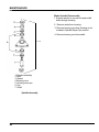
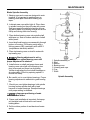
Blade Spindle Installation
1. Insert spindle through bottom of mower deck
and install three mounting bolts. Be sure to
position grease fittings toward lubrication
access areas. Refer to lubrication chart.
D E E E l Pulley installation sequence is
very important for bearing life. Follow the
sequence exactly.
2. Install pulley and split taper bushing with integral key on spindle shaft. Install bolt and flat
washer in top of spindle shaft. Torque this bolt
to 1.7 kg/cm (12 ft/lbs), then alternately tighten
split taper bushing bolts to 1.7 kg/cm (12 ft/lbs).
MAINTENANCE
6
UNIVERSAL JOINT REPAIR
m5
1. Yoke
2. Journal cross
3. Seal
4. Snap ring
5. Cup and bearings
6. Yoke
Universal Joint Assembly
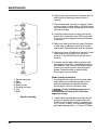
Disassembly
1. Remove snap rings from inside of yokes in four
locations as shown.
2. With snap rings removed, support drive in vise,
hold yoke in hand and tap on yoke to drive cup
out of yoke.
47
MAINTENANCE
3. Clamp cup in vise as shown and tap on yoke
to completely remove cup from yoke. Repeat
steps two and three for opposite cup.
h
..
L11'
4. Place universal cross in vise as shown and tap
on yoke to remove cup. Repeat step three for
final removal. Drive remaining cup out with drift
and hammer.
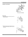
Assembly
1.Place seals securely on bearing cups. Insert
cup into yoke from outside and press on with
hand pressure as far as possible. Insert journal
cross into bearing cup with grease fitting away
from shaft. Be careful not to disturb needle
bearings. Insert another bearing cup directly
across from first cup and press in as far as
possible with hand pressure.
2. Trap cups in vise and apply pressure. Be sure
journal cross is started into bearings and
continue pressure with vise, squeezing in as far
as possible. Tap yoke to aid in process.
3. Seat cups by placing a drift (slightly smaller
than the cup) on cup and rapping with hammer. Install snap ring and repeat on opposite
cup.
4. Repeat steps one and two to install remaining
cups in remaining yoke.
5. Move both yokes in all directions to check for
free movement. Should movement be restricted, rap on yokes sharply with a hammer to
relieve any tension. Repeat until both yokes
move in all directions without restriction.
48
MAINTENANCE
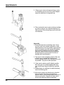
GEARBOX MAINTENANCE
Read this complete section before starting any
repair. Many steps are dependent on each other.
Seal
1. Gearbox bearings, gears and shafts have an
interference press fit. Gearbox repair is limited
to seal; gasket and vent plug replacement.
&
-
Vent Plug
2. Always maintain correct gear lube level in
gearbox. Be sure proper vent plug is installed.
3. Troubleshooting is an important part of gearbox
maintenance. Check for leakage and bad
bearings.
4. Leakage is a very serious problem and must be
corrected immediately or damage to gearbox
and belt will result. Remove gearbox from
mower to repair leakage problems.
Seal
u
gasket
Gear Box
5. Leakage may be caused by a vent plug not
venting. To check vent plug operation, remove
plug and apply low air pressure to opening in
side of plug. Check to make sure it is venting
out of the top.
6. Operating gearbox with improper lube level
may also cause seals to leak. Also check for
housing cracks. If any of these conditions exist,
correct them, clean area where leakage was
evident, return mower to service and check to
make sure leakage has been stopped.
7. Bearing maladjustment or failure is indicated by
noise and excessive side and end play in gear
shafts. If noted, replace the gearbox.
Removing Gearbox from Mower
1. Disconnect drive shaft and remove key. Remove belt and remove gear stand from mower.
2. Turn gear stand over. There are two set screws
in the split taper bushing; remove them. Insert
one set screw into the threaded bushing hole
and tighten to force bushing and pulley apart.
3. Remove gearbox from stand.
49
MAINTENANCE
Leakage Repair
1. Bore-tite™, a sealant, is used on the outer
diameter of the seals. Substitute seals may not
meet original equipment specifications and
could cause leakage.
2. Clean gearbox exterior to remove all foreign
material. When opening, use care to prevent
foreign material from entering gearbox.
Seal
e-
\
Vent Plug
al
Seal
Gearbox gasket
1
Gear Box
3. To repair horizontal seal, vertical shaft, or
leakage between cover and gearbox, remove
vent plug and drain gear lube from box. Remove leaking seal and replace (refer to Seal
Installation). Use care to prevent rolling seal lip
under. Replace gasket between cover and.
gearbox.
Seal Installation
Proper seal installation is important. An improperly
installed seal will leak and could result in bearing
failure.
1. Clean areas in housing where seal outer diameter seats. Inspect gear shafts. Pay specific
attention to areas where seals seat. Check for
cracks, grooves, nicks or bumps. Replace
housing or shaft if damage cannot be repaired
by resurfacing with emery cloth.
2. Lubricate seal lip and carefully guide over shaft
using a blunt tool such as a letter opener. Be
careful not to roll seal lip under. Do not use a
knife as it will nick and ruin seal.
3. Place seal squarely on housing (spring-loaded
lip toward inside of gearbox). Select a seal
driver, a piece of pipe or tubing with an OD that
will set on outside edge of seal but will clear
housing. A driver that is too small will bow seal
cage and ruin seal.
4. Carefully press seal into housing, preventing
distortion to metal seal cage. Seat vertical seal
flush with housing and horizontal seal against
shoulder in housing.
5. Distortion to seal case or damage to seal lip will
cause seal to leak. Remove and replace seals
damaged in installation.
6. Check for proper vent plug operation and fill
gearbox with 8 oz. of SAE 90W gear lube.
50
MAINTENANCE
Drive Pulley Installation
1. Install drive pulley with split taper bushing on
gearbox vertical shaft. Make sure key and
keyways are aligned.
3
2. Position centerline of driie pulley 0.98 & 0.030 in.
above mounting surface of gearbox stand as
shown. This is a very criiical dimension and
must be held. Alternately tighten split taper
bushing set screws to 2 kg/m (14 ft/bs). Check
mounting distance to make sure it is correct.
1. Split taper bushing
2. Drive pulley
3. Gearbox stand
4. Key
Drive Pulley Assembly
51
STORAGE
STORAGE
1. Remove the mower deck from the tractor.
2. Turn the mower deck upside down. Clean the
underside of the deck with water, and dry
thoroughly.
3. For longer service and greater efficiency, keep
the underside of the mower housing clean and
free of accumulated grass clippings by washing
it down with a hose after use and/or cleaning it
with a wire brush and scraper. Remove any rust
and apply a rust-resistant paint. Cleaning and
rust prevention are especially important before
seasonal storage.
Washing the deck directly after
use can cause premature bearing wear.
Allow the deck to cool before washing, then
run the deck to remove any excess moisture.
1-
TROUBLESHOOTING
PROBLEM
1. Mower overloading; material too tall or heavy
2. Oil on belt from over-lubrication
3. Belt hung up or rubbing
4. Belt or pulleys worn out
~~~
~
SOLUTION
1. Reduce tractor speed but operate Mid-PTO at
2400 rpm. Cut material twice: one high pass,
then mow at desired height, Cut a partial swath.
2. Be careful not to over-lubricate. Clean lubricant
from belt and pulleys with clean rag. Replace
oil-soaked belt.
3. Check belt for free travel in pulleys and belt
guides. Check under mower and around blade
spindle shafts for wire, rags or other foreign material. Clean all material from under mower.
4. If belt rides in bottom of pulley groove, either
belt or pulley is worn and must be replaced.
~
1. Belt misaligned or rubbing guide
1. Damaged belt
2. Worn pulley groove
1. Re-align belt or guide. Be sure belt doesn't rub
any other part while running.
1. Lay belt flat on floor. If belt does not lie flat (has
humps or twists), indicating broken or stretched
cords, it must be replaced.
2. Replace pulley.
1. Rollover, high shock loads or installation
damage
1. Replace belt.
1. High shock loads
1. Avoid abusive mowing. Avoid hitting the ground
or obstructions.
2. Check drive alignment for foreign material in
grooves. Avoid hitting solid objects or ground.
2. Belt came off driie
53
TROUBLESHOOTING
PROBLEM
SOLUTION
~~~
~~~
1. Tractor speed too fast
2. Grass accumulation inside deck
3. Dull Blade
4. Tires improperty inflated
5. Mower not level
6. Wrong mower deck height
7. Engine speed too low
1. Shift to lower gear.
2. Clean deck underside.
3. Have the blade sharpened or replace it.
4. Check the tire inflation.
5. Check the blade height.
6. Change to proper height.
7. Run at full throttle.
1. Blade driie belt worn or broken
2. Mid PTO not selected
3. Faulty PTO clutch or worn disk
1. Replace with new belt.
2. Check PTO Selector Lever position
3. See your authorized HONDA Multi-purpose
Tractor dealer.
1. Wrong blade
2. Deck too low
3. Engine overloaded
1. Use genuine HONDA blade or equivalent.
2. Raise deck and adjust deck height properly.
3. Operate at full throttle. Use lower speed range.
Set mower deck higher than ,desired height for
first pass, then cut to desired height on second
pass.
4. Allow to dry before cutting.
5. Set mower deck higher than desired height for
first pass, then cut to desired height on second
pass.
6. Run at full throttle. (Do not exceed 2400 rpms
on Mid-PTO.)
4. Lawn wet or watered
5. Lawn too tall
6. Engine speed too low
~~
_ _ _ _ ~ ~ ~
~
1. Cutting height too low
2. Tractor speed too high
3. Uneven surface
4. Rough and uneven surface
1. Unbalanced blades
2. Driveblade belt damaged
3. Pulley(s) damaged or out of alignment
4. Lack of gearbox lubricant
1. Engine speed too low
2. Tractor speed too fast
3. Pebbles or other foreign matter are stuck
in mower deck
54
,
1. Increase to proper height.
2. Lower to proper speed.
3. Change cutting pattern.
4. Adjust with height adjuster.
1. Adjust balance.
2. Replace.
3. See your authorized HONDA multi-purpose
tractor dealer.
4. Lubricate with SAE 90 weight gear lubricant
1. Run at full throttle. (Do not exceed 2400 rpms
on Mid-PTO.)
2. Lower to proper speed range.
3. Remove.
SPECIFICATIONS
Overall length
1345 mm (53.8")
Overall width
1820 mm (72.8")
Mowing width
1500 mm (60")
140 kg (280 Ibs)
Weight (including linkage)
Tractor mid-PTO operating speed
Cutting height range
2,400 rpm maximum
1-1/2" to 4"
Number of blades
3
Max. lifting height
6" to blade face (4" w/ FL6555 sub frame)
Caster wheels
3-1/4"
Mower frame thickness
8 GA deck
X
6-114"
55
WARRANTY SERVICE
OWNER SATISFACTION
Your satisfaction and goodwill are important to your dealer and to us. All HONOA warranty details are
explained in the Distributor's Limited Warranty. Normally, any problems concerning the product will be
handled by your dealer's service department. If you have a warranty problem that has not been handled to
your satisfaction, we suggest you take the following action
Discuss your problem with a member of dealership management. Often complaints can be quickty
resolved at that level. If the problem has already been reviewed with the Service Manager, contact the
owner of the dealership or the General Manager.
If your problem still has not been resolved to your satisfaction, contact the Power Equipment Customer
Service Department of American Honda Motor Co., Inc.
AMERICAN HONDA MOTOR CO., INC.
Power Equipment Customer Service Dept.
Duluth, Georgia 30136-9421
Telephone: (404) 497-6400
We will need the following information in order to assist you:
- Your name, address and telephone number
- Product model and serial number
- Date of purchase
- Dealer name and address
- Nature of problem
After reviewing all the facts involved, you will be advised of what action can be taken. Please bear in mind
that your problem will likely be resolved at the dealership, using the dealer's facilities, equipment and
personnel, so it is very important that your initial contacts be with the dealer.
Your purchase of a HONDA product is greatly appreciated by both your dealer and American Honda
Motor Co., Inc. We want to assist you in every way possible to assure your satisfaction with your purchase.
56
Current customer service contact information:
United States, Puerto Rico, and U.S. Virgin Islands:
Honda Power Equipment dealership personnel are trained professionals. They should
be able to answer any question you may have. If you encounter a problem that your
dealer does not solve to your satisfaction, please discuss it with the dealership's
management. The Service Manager or General Manager can help. Almost all problems
are solved in this way.
If you are dissatisfied with the decision made by the dealership's management, contact
the Honda Power Equipment Customer Relations Office. You can write:
American Honda Motor Co., Inc.
Power Equipment Division
Customer Relations Office
4900 Marconi Drive
Alpharetta, GA 30005-8847
Or telephone: (770) 497-6400 M-F, 8:30 am - 5:00 pm EST
When you write or call, please provide the following information:
•
Model and serial numbers
•
Name of the dealer who sold the Honda power equipment to you
•
Name and address of the dealer who services your equipment
•
Date of purchase
•
Your name, address, and telephone number
•
A detailed description of the problem