1
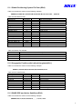
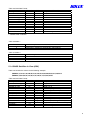
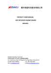
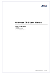
GR-213U
GPS Receiver
User’s
Guide
Dec. 25 2005
Rev. A
Technology, Inc.
1F.No 30, R&D Rd. II. Hsinchu City, Science-based Industrial Park Taiwan
Phone: +886-3-6687000 Fax: +886-3-6687111
E-Mail: [email protected] Web: www.holux.com
All Right Reserved
TABLE OF CONTENTS
1. Introduction ..................................................................................3
1.1 Overview ............................................................................................................... 3
1.2 Features ................................................................................................................ 3
1.3 Technology specifications ..................................................................................... 3
2. Operational characteristics.........................................................4
2.1 Initialization............................................................................................................ 4
2.2 Navigation ............................................................................................................. 4
3. Hardware interface.......................................................................5
3.1 Dimension ............................................................................................................. 5
3.2 Hardware Connection............................................................................................ 5
4. USB Driver ....................................................................................6
4.1 System Requirements ........................................................................................... 6
4.2 Installation ............................................................................................................. 6
4.3 Important ............................................................................................................... 6
5. Software Interface........................................................................6
5.1 NMEA Transmitted Messages............................................................................... 6
6. Warranty .......................................................................................100
2
1. Introduction
1.1 Overview
GR-213U Smart GPS Receiver is a total solution GPS receiver, designed based on SiRF Star III
Architecture. This positioning application meets strict needs such as car navigation, mapping, surveying,
security, agriculture and so on. Only clear view of sky and certain power supply are necessary to the unit. It
communicates with other electronic utilities via compatible dual-channel through USB interface and saves
critical satellite data by built–in backup memory. With low power consumption, the GR-213U tracks up to 20
satellites at a time, re-acquires satellite signals in 100 ms and updates position data every second.
Trickle-Power allows the unit operates a fraction of the time and Push-to-Fix permits user to have a quick
position fix even though the receiver usually stays off.
1.2 Features
The GR-213U provides a host of features that make it easy for integration and use.
1. SiRFstarIII chipset with embedded ARM7TDMI CPU available for customized applications in firmware
2. High performance receiver tracks up to 20 satellites while providing first fast fix and low power
consumption.
3. Compact design ideal for applications with minimal space.
4. A rechargeable battery sustains internal clock and memory. The battery is recharged during normal
operation.
5. Users can adjust power-saving percentage (20%~80%), which achieves the best power efficiency.
6. User initialization is not required.
7. LED display status: The LED provides users visible positioning status. LED “ON” when power connected
and “BLINKING” when GR-213U got positioned.
8. Water proof design for industry standard.
1.3 Technology specifications
1.3.1 Physical Dimension
Single construction integrated antenna/receiver.
Size: 64.5 x 42 x 17.8 (mm)
2.54" x 1.65 x 0.7 (Inch).
1.3.2 Environmental Characteristics
1) Operating temperature: -40oC to +80oC(internal temperature).
2) Storage temperature: -45oC to +100oC.
1.3.3 Electrical Characteristics
1) Input voltage: +4.5 ~ 5.5 VDC without accessories.
2) Backup power: 3V Rechargeable Lithium cell battery, up to 500 hours discharge.
1.3.4 Performance
1) Tracks up to 20 satellites.
2) Update rate: 1 second.
3) Acquisition time
Reacquisition 0.1 sec., averaged
Hot start
8 sec., averaged
Warm start
38 sec., averaged
Cold start
42 sec., averaged
4) Position accuracy:
A) Non DGPS (Differential GPS)
Position
5-25 meter CEP without SA
Velocity
0.1 meters/second, without SA
Time
1
microsecond synchronized GPS time
3
B) EGNOS/WAAS/Beacon
Position
< 2.2 meters, horizontal 95% of time
< 5 meters, vertical 95% of time
5) Dynamic Conditions:
Altitude
18,000 meters (60,000 feet) max
Velocity
515 meters / second (700 knots) max
Acceleration
4 G, max
Jerk
20
meters/second, max
1.3.5 USB Interfaces
1) USB interface with user selectable baud rate (4800-Default, 9600, 19200, 38400).
2) NMEA 0183 Version 2.2 ASCII output GGA, GSA, GSV, RMC (option GLL, VTG, ZDA).
3) SiRF binary protocol.
2. Operational characteristics
2.1 Initialization
As soon as the initial self-test is complete, the GR-213U begins the process of satellite acquisition and tracking
automatically. Under normal circumstances, it takes approximately 42 seconds to achieve a position fix, 38
seconds if ephemeris data is known. After a position fix has been calculated, information about valid position,
velocity and time is transmitted over the output channel.
The GR-213U utilizes initial data, such as last stored position, date, time and satellite orbital data, to achieve
maximum acquisition performance. If significant inaccuracy exists in the initial data, or the orbital data is
obsolete, it may take more time to achieve a navigation solution. The GR-213U Auto-locate feature is capable
of automatically determining a navigation solution without intervention from the host system. However,
acquisition performance can be improved as the host system initializes the GR-213U in the following situation:
1) Moving further than 500 kilometers.
2) Failure of data storage due to the inactive internal memory battery.
2.2 Navigation
After the acquisition process is complete, the GR-213U sends valid navigation information over output channels.
These data include:
1)
2)
3)
4)
5)
Latitude/longitude/altitude
Velocity
Date/time
Error estimates
Satellite and receiver status
4
3. Hardware interface
3.1 Dimension
3.2 Hardware Connection
1) The GR-213U includes an antenna in a unique style waterproof gadget. With the USB connector, you can
easily access to your notebook PC, or other USB devices.
2) USB connector
The USB A Type is equipped with GR-213U. The function definition is as follows:
Pin
1
2
3
4
Signal Name
+5V
D+
DGround
5
4. USB Driver
4.1 System Requirements
IBM, Pentium compatible PC and above.
16 MB memory and above
Windows 98/Me/2000/XP;
VGA Graphic Adapter.
4.2 Installation
1. Copy the <GR-213U->English->USB Driver->Win98_2k_XP>USB-V2.1.0.exe from CD to hard disk.
2. Install USB-V2.1.0.exe.
3. Plug the GR-213U USB connector into the computer, the computer will search plug and play (P&P) device
automatically, and the installation of GR-213U USB Driver is complete.
4.3 Important
Verify the COM port # to start using your own navigating software.
1. Click <Start> menu, select <Settings>, then enter <Control Panel>.
2. After entering <Control Panel>, select <System>.
3. Select <Device Manager>.
4. Find the <Connect port> and check the Virtual COM Port, which was created by the USB driver,
Please note that the Virtual COM Port number might be different from every computer. Before using
navigating software, please confirm the COM Port numbers created by your computer and provided by
your navigation software. Otherwise, the navigating software won’t receive the satellite signal, because of
the un-match COM Port setting.
“#” sign represents the COM port number that being created by USB port. Usually the value will be
COM1 in normal navigation software. So the correct COM port of the navigation software needs to
be the same as the one in PC that created by USB port, and then the navigation is able to receive
correct data.
5. Software Interface
The GR-213U interface protocol is based on the National Marine Electronics Association's NMEA 0183 ASCⅡ
interface specification, which is defined in NMEA 0183, Version 2.2 and the Radio Technical Commission for
Maritime Services (RTCM Recommended Standards For Differential Navstar GPS Service, Version 2.1, RTCM
Special Committee No.104, Type 1,2,9) or WAAS (in USA area) or EGNOS (in European area).
5.1 NMEA Transmitted Messages
The GR-213U supported by SiRF Technology Inc. also outputs data in NMEA-0183 format as defined by the
National Marine Electronics Association (NMEA), Standard.
The default communication parameters for NMEA output are 4800 baud, 8 data bits, stop bit, and no parity.
Table 5-1 NMEA-0183 Output Messages
NMEA Record
Description
GPGGA
Global positioning system fixed data
GPGLL
Geographic position- latitude/longitude
GPGSA
GNSS DOP and active satellites
GPGSV
GNSS satellites in view
GPRMC
Recommended minimum specific GNSS data
GPVTG
Course over ground and ground speed
6
5.1.1 Global Positioning System Fix Data (GGA)
Table 5-2 contains the values for the following example:
$GPGGA,161229.487,3723.2475,N,12158.3416,W,1,07,1.0,9.0,M, , , ,0000*18
Table 5-2 GGA Data Format
Name
Example
Message ID
$GPGGA
UTC Time
161229.487
Latitude
3723.2475
N/S Indicator
N
Longitude
12158.3416
E/W Indicator
W
Position Fix Indicator
1
Satellites Used
07
HDOP
1.0
MSL Altitude
9.0
Units
M
Geoid Separation
Units
M
Age of Diff. Corr.
Diff. Ref. Station ID
0000
Checksum
*18
<CR> <LF>
Units
Meters
Meters
Meters
Meters
second
Description
GGA protocol header
hhmmss.sss
ddmm.mmmm
N=north or S=south
dddmm.mmmm
E=east or W=west
See Table 5-3
Range 0 to 20
Horizontal Dilution of Precision
Null fields when DGPS is not used
End of message termination
Table 5-3 Position Fix Indicator
Value
Description
0
0 Fix not available or invalid
1
GPS SPS Mode, fix valid
2
Differential GPS, SPS Mode, fix valid
3
GPS PPS Mode, fix valid
5.1.2 Geographic Position with Latitude/Longitude(GLL)
Table 5-4 contains the values for the following example:
$GPGLL,3723.2475,N,12158.3416,W,161229.487,A*2C
Table 5-4 GLL Data Format
Name
Example
Message ID
$GPGLL
Latitude
3723.2475
N/S Indicator
N
Longitude
12158.3416
E/W Indicator
W
UTC Position
161229.487
Status
A
Checksum
*2C
<CR> <LF>
Units
Description
GLL protocol header
ddmm.mmmm
N/S Indicator N N=north or S=south
dddmm.mmmm
E=east or W=west
hhmmss.sss
A=data valid or V=data not valid
End of message termination
5.1.3 GNSS DOP and Active Satellites (GSA)
Table 5-5 contains the values for the following example:
$GPGSA,A,3,07,02,26,27,09,04,15, , , , , ,1.8,1.0,1.5*33
7
Table 5-5 GSA Data Format
Name
Example
Message ID
$GPGSA
Mode 1
A
Mode 2
3
Satellite Used(1)
07
Satellite Used (1)
02
……
Satellite Used
PDOP
1.8
HDOP
1.0
VDOP
1.5
Checksum
*33
<CR> <LF>
Units
Description
GSA protocol header
See Table 5-6
See Table 5-7
Sv on Channel 1
Sv on Channel 2
….
Sv on Channel 20
Position Dilution of Precision
Horizontal Dilution of Precision
Vertical Dilution of Precision
End of message termination
1. Satellite used in solution.
Table 5-6 Mode 1
Value
M
A
Table 5-7 Mode 2
Value
1
2
3
Description
Manual—forced to operate in 2D or 3D mode
2DAutomatic—allowed to automatically switch 2D/3D
Description
Fix Not Available
2D
3D
5.1.4 GNSS Satellites in View (GSV)
Table 5-8 contains the values for the following example:
$GPGSV,2,1,07,07,79,048,42,02,51,062,43,26,36,256,42,27,27,138,42*71
$GPGSV,2,2,07,09,23,313,42,04,19,159,41,15,12,041,42*41
Table 5-8 GSV Data Format
Name
Example
Message ID
$GPGSV
Number of Messages
2
Message Number
1
Satellites in View
07
Satellite ID
07
Elevation
79
Azimuth
048
SNR (C/No)
42
....
....
Satellite ID
27
Elevation
27
Azimuth
138
SNR (C/No)
42
Checksum
*71
<CR> <LF>
Units
degrees
degrees
dBHz
Description
GSV protocol header
Range 1 to 3
Range 1 to 3
Range 1 to 12
Channel 1 (Range 1 to 32)
Channel 1 (Maximum 90)
Channel 1 (True, Range 0 to 359)
Range 0 to 99, null when not tracking
degrees
degrees
dBHz
Channel 4 (Range 1 to 32)
Channel 4 (Maximum 90)
Channel 4 (True, Range 0 to 359)
Range 0 to 99, null when not tracking
End of message termination
8
NOTE: Items <4>,<5>,<6> and <7> repeat for each satellite in view to a maximum of four (4) satellites per
sentence. Additional satellites in view information must be sent in subsequent sentences. These fields will be
null if unused.
5.1.5 Recommended Minimum Specific GNSS Data (RMC)
Table 5-9 contains the values for the following example:
$GPRMC,161229.487,A,3723.2475,N,12158.3416,W,0.13,309.62,120598, ,*10
Table 5-9 RMC Data Format
Name
Example
Units
Description
Message ID
$GPRMC
RMC protocol header
UTC Time
161229.487
hhmmss.sss
Status
A
A=data valid or V=data not valid
Latitude
3723.2475
ddmm.mmmm
N/S Indicator
N
N=north or S=south
Longitude
12158.3416
dddmm.mmmm
E/W Indicator
W
E=east or W=west
Speed Over Ground
0.13
knots
Course Over Ground
309.62
degrees True
Date
120598
ddmmyy
Magnetic Variation (1)
degrees E=east or W=west
Checksum
*10
<CR> <LF>
End of message termination
1. SiRF Technology Inc. does not support magnetic declination. All “course over ground” data are geodetic
WGS84 directions.
5.1.6 Course Over Ground and Ground Speed (VTG)
Table 5-10 contains the values for the following example:
$GPVTG,309.62,T, ,M,0.13,N,0.2,K*6E
Table 5-10 VTG Data Format
Name
Example
Units
Description
Message ID
$GPVTG
VTG protocol header
Course
309.62
degrees Measured heading
Reference
T
True
Course
degrees Measured heading
Reference
M
Magnetic (1)
Speed
0.13
knots
Measured horizontal speed
Units
N
Knots
Speed
0.2
km/hr
Measured horizontal speed
Units
K
Kilometers per hour
Checksum
*6E
<CR> <LF>
End of message termination
1. SiRF Technology Inc. does not support magnetic declination. All “course over ground” data are geodetic
WGS84 directions.
5.1.7 ZDA—SiRF Timing Message
Outputs the time associated with the current 1 PPS pulse. Each message will be output within a few
hundred ms after the 1 PPS pulse is output and will tell the time of the pulse that just occurred.
Table 5-11 contains the values for the following example:
$GPZDA,181813,14,10,2003,00,00*4F
9
Table 5-11 ZDA Data Format
Name
Example
Message ID
$GPZDA
UTC Time
181813
Day
Month
Year
Local zone hour
Local zone hour
Checksum
<CR> <LF>
14
10
2003
00
00
4F
Units
knots
Description
ZDA protocol header
Either using valid IONO/UTC or estimated
from default leap seconds
01 TO 31
01 TO 12
1980 to 2079
Offset from UTC (set to 00)
Offset from UTC (set to 00)
End of message termination
6. Warranty
The GR-213U is warranted to be free from defects in material and functions for one year from the date of
purchase. Any failure of this product within this period under normal conditions will be replaced at no charge to
the customers.
10