1
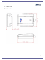
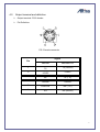
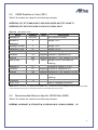
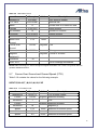
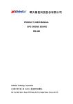
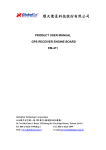
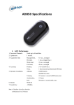
G-Mouse GPS User Manual
GPS GGM308
PS-2 Connector
Version 1.01 2004 / 09 / 16
i
Copyright is reserved by Altina
INDEX
1
OVERVIEW ...........................................................................................................3
2
PRODUCT FEATURE .......................................................................................3
3
SPECIFICATION.................................................................................................4
4
HARDWARE .........................................................................................................6
4.1.
4.2.
5.
SOFTWARE DATA.............................................................................................8
5.1.
5.2.
5.3.
5.4.
5.5.
5.6.
5.7.
5.8.
6.
DIMENSION ................................................................................................................6
OUTPUT TERMINAL AND DEFINITION ....................................................................7
NMEA OUTPUT MESSAGE.....................................................................................8
GLOBAL POSITIONING SYSTEM FIX DATA (GGA) ............................................8
GEOGRAPHIC POSITION WITH LATITUDE/LONGITUDE(GLL) ..........................9
GNSS DOP AND ACTIVE SATELLITES (GSA) .................................................10
GNSS SATELLITES IN VIEW (GSV) ...................................................................11
RECOMMENDED MINIMUM SPECIFIC GNSS DATA (RMC) ..........................11
COURSE OVER GROUND AND GROUND SPEED (VTG) ...................................12
RTCM RECEIVED DATA.......................................................................................13
WARRANTY ........................................................................................................13
i
Copyright is reserved by Altina
1 OVERVIEW
Congratulation on your purchase of Altina, which manufacture and provide various
GPS applications. Altina’s GGM308 GPS Receiver provides you various applications
such as car navigation, marine navigation, mapping, surveying, security, agriculture and so
on. It communicates with device (such as PocketPC or notebook) via compatible
dual-channel through RS-232 or TTL and saves satellite data by built–in backup memory.
Low power consumption technology enables GGM308 and your device to save more
operating power. Furthermore, GGM308 can track up to 12 satellites at a time, re-acquire
satellite signals in 100ms and update position data every second. Trickle-Power allows
the unit to operate a fraction of the time, and Push-to-Fix permits user to have a quicker
position fix even though the receiver stays off.
2 PRODUCT FEATURE
SiRF Star Ⅱe/LP ”High Performance and Low Power Consumption Chipset
Integrated ARM7TDMI CPU
Cold Start : within 45 seconds.
A rechargeable battery sustains internal clock and memory and can be recharged
during normal operation.
All-in-View 12-channel parallel processing.
Support NMEA 0183 V2.2 command
Optional communication levels, RS-232 and TTL
Reacquisition Time: 0.1 seconds
Support Accurate 1PPS Output Signal Aligned with GPS Timing
Water proof design enable receiver to continuously operate for 4 days under
1meter water deep.
Built-in hardware Tracking Loop Processor WAAS/EGNOS Demodulator and
NDGPS/U.S. Coast Guard Beacon support
Obvious LED display status: LED provides users visible positioning status. LED
“ON” : power connected; “BLINKING”: positioned.
3
Differential capability utilizes real-time RTCM corrections to provide 1-5 meter
precise position accuracy.
FLASH base program memory
3 SPECIFICATION
Key Feture
Frequency
C/A Code
Channels
Sensitivity
L1, 1575.42 MHz
1.023 MHz chip rate
12
-173 dBW
Non DGPS (Differential GPS)
Position Horizontal
Velocity
Time
5 to 25 meter CEP, without SA
0.1 meter/second, without SA
1 microsecond synchronized GPS time
DGPS (Differential GPS)
Position Horizontal 1 to 5 meter, typical
Velocity
0.05 meter/second, typical
EGNOS/WAAS
< 2.2 m, horizontal 95% of time
Datum
WGS-84
Performance
Hot start
Warm start
Cold start
Reacquisition
GPS Protocol
GPS Output Data
GPS transfer rate
8 sec., average
38 sec., average
45 sec., average
0.1 sec. average
Default: NMEA 0183 V2.2 (Secondary: SiRF binary)
SiRF binary >> position, velocity, altitude, status and control ;
NMEA 0183 protocol, and supports command:
GGA, GSA, GSV, RMC, VTG, GLL (VTG and GLL are optional)
Software command setting (Default : 4800,n,8,1 for NMEA )
Acceleration Limit
Altitude Limit
Velocity Limit
Jerk Limit
Operating
Less than 4g
18,000 meters (60,000 feet) ma
515 meters/sec. (1,000 knots) max.
20 meters/second, max
-40oC to +85oC(internal temperature).
4
Storage
Input Voltage
Power consumption
-45oC to +100oC
+4.75 ~ 5.5 VDC without accessories.
<80mA at 4.5- 5.5V input
Dimension
Cable Length
2.32" x 1.85" x 0.82" (59.32mm x 51.28mm x 20.3mm)
60" (1500mm)
5
4 HARDWARE
4.1. Dimension
6
4.2. Output terminal and definition
Output terminal: PS-2 female
Pin Definition:
PS-2 female connector
Signal
Pin
RS-232
RS-232+TTL
1
TX
TX (RS232)
2
+5VDC
+5VDC
3
NC
TX (TTL)
4
Ground
Ground
5
DGPS IN
RX (TTL)
6
RX
RX (RS232)
7
5. SOFTWARE DATA
NMEA 0183 V2.2 Protocol
Use RS-232 interface:4800 bps, 8 bit data, 1 stop bit and no parity.
5.1. NMEA Output Message
Table 5-1
NMEA-0183 Output Messages
NMEA Record
Description
GPGGA
Global positioning system fixed data
GPGLL
Geographic position: latitude/longitude
GPGSA
GNSS DOP and active satellites
GPGSV
GNSS satellites in view
GPRMC
Recommended minimum specific GNSS data
GPVTG
Course over ground and ground speed
5.2. Global Positioning System Fix Data (GGA)
Table 5-2 contains the values for the following example
$GPGGA,161229.487,3723.2475,N,12158.3416,W,1,07,1.0,9.0,M, , , ,0000*18
Table 5-2
GGA Data Format
Name
Message ID
Example
Units
$GPGGA
Description
GGA protocol header
UTC Time
161229.487
hhmmss.sss
Latitude
3723.2475
ddmm.mmmm
N/S Indicator
Longitude
N
N=north or S=south
12158.3416
dddmm.mmmm
E/W Indicator
W
E=east or W=west
Position Fix Indicator
1
See Table 5-3
Satellites Used
07
Range 0 to 12
HDOP
1.0
Horizontal Dilution of Precision
MSL Altitude
9.0
Meters
8
Table 5-2
GGA Data Format-continue
Name
Example
Units
M
Meters
Units
Geoid Separation
Meters
Units
M
Meters
Age of Diff. Corr.
second Null fields when DGPS is not used
Diff. Ref. Station ID
0000
Checksum
*18
<CR> <LF>
Table 5-3
Description
End of message termination
Position Fix Indicator
Value
Description
0
0 Fix not available or invalid
1
GPS SPS Mode, fix valid
2
Differential GPS, SPS Mode, fix valid
3
GPS PPS Mode, fix valid
5.3. Geographic Position with Latitude/Longitude(GLL)
Table 5-3 contains the values for the following example.
$GPGLL,3723.2475,N,12158.3416,W,161229.487,A*2C
Table 5-4
GLL Data Format
Name
Message ID
Latitude
N/S Indicator
Longitude
Example
$GPGLL
3723.2475
N
12158.3416
E/W Indicator
W
UTC Position
161229.487
Status
Checksum
<CR> <LF>
A
Units
Description
GLL protocol header
ddmm.mmmm
N/S Indicator N N=north or S=south
dddmm.mmmm
E=east or W=west
hhmmss.sss
A=data valid or V=data not valid
*2C
End of message termination
9
5.4. GNSS DOP and Active Satellites (GSA)
Table 5-4 contains the values for the following example.
$GPGSA,A,3,07,02,26,27,09,04,15, , , , , ,1.8,1.0,1.5*33
Table 5-5
GSA Data Format
Name
Example
Message ID
$GPGSA
Units
Description
GSA protocol header
Mode 1
A
See Table 5-6
Mode 2
3
See Table 5-7
Satellite Used(1)
07
Sv on Channel 1
Satellite Used(1)
02
Sv on Channel 2
Satellite Used
Sv on Channel 12
PDOP
1.8
Position Dilution of Precision
HDOP
1.0
Horizontal Dilution of Precision
VDOP
1.5
Vertical Dilution of Precision
Checksum
*33
<CR> <LF>
End of message termination
NOTE: Satellite used in solution.
Table 5-6
Mode 1
Value
Description
M
Manual—forced to operate in 2D or 3D mode
A
2DAutomatic—allowed to automatically switch 2D/3D
Table 5-7
Mode 2
Value
Description
1
Fix Not Available
2
2D
3
3D
10
5.5.
GNSS Satellites in View (GSV)
Table 5-8 contains the values for the following example
$GPGSV,2,1,07,07,79,048,42,02,51,062,43,26,36,256,42,27,27,138,42*71
$GPGSV,2,2,07,09,23,313,42,04,19,159,41,15,12,041,42*41
Table 5-8
GSV Data Format
Name
Message ID
Example
Units
$GPGSV
Description
GSV protocol header
Number of
Messages
2
Range 1 to 3
Message Number
1
Range 1 to 3
Satellites in View
07
Range 1 to 12
Satellite ID
07
Channel 1 (Range 1 to 32)
Elevation
79
degrees Channel 1 (Maximum 90)
Azimuth
048
degrees Channel 1 (True, Range 0 to 359)
SNR (C/No)
42
Satellite ID
27
Elevation
27
degrees Channel 4 (Maximum 90)
Azimuth
138
degrees Channel 4 (True, Range 0 to 359)
SNR (C/No)
42
Checksum
*71
<CR> <LF>
dBHz
Range 0 to 99, null when not
tracking
Channel 4 (Range 1 to 32)
dBHz
Range 0 to 99, null when not
tracking
End of message termination
NOTE: Items <4>,<5>,<6> and <7> repeat for each satellite in view to a maximum of four (4) satellites per sentence. Additional satellites
in view information must be sent in subsequent sentences. These fields will be null if unused.
5.6. Recommended Minimum Specific GNSS Data (RMC)
Table 5-9 contains the values for the following example.
$GPRMC,161229.487,A,3723.2475,N,12158.3416,W,0.13,309.62,120598, ,*10
11
Table 5-9
RMC Data Format
Name
Message ID
UTC Time
Example
Units
$GPRMC
RMC protocol header
161229.487
Status
hhmmss.sss
A
Latitude
A=data valid or V=data not valid
3723.2475
N/S Indicator
Longitude
ddmm.mmmm
N
N=north or S=south
12158.3416
E/W Indicator
dddmm.mmmm
W
Speed Over
Ground
0.13
Course Over
Ground
309.62
Date
120598
Magnetic
Variation(1)
Description
E=east or W=west
knots
degrees True
ddmmyy
degrees E=east or W=west
Checksum
*10
<CR> <LF>
End of message termination
NOTE: SiRF Technology Inc. does not support magnetic declination. All “course over ground” data are
geodetic WGS84 directions.
5.7. Course Over Ground and Ground Speed (VTG)
Table 5-10 contains the values for the following example.
$GPVTG,309.62,T, ,M,0.13,N,0.2,K*6E
Table 5-10
VTG Data Format
Name
Example
Message ID
$GPVTG
Course
309.62
Reference
T
Course
Units
Description
VTG protocol header
degrees Measured heading
True
degrees Measured heading
Reference
M
Speed
0.13
Units
N
Speed
0.2
Magnetic(1)
knots
Measured horizontal speed
Knots
km/hr
Measured horizontal speed
12
Units
K
Checksum
*6E
<CR> <LF>
Kilometers per hour
End of message termination
NOTE: SiRF Technology Inc. does not support magnetic declination. All “course over ground” data are
geodetic WGS84 directions.
5.8. RTCM Received Data
The default communication parameters for DGPS Input are 4800 baud, 8 data bits, stop bit,
and no parity. Position accuracy of less than 5 meters can be achieved with the GGM-308
by using Differential GPS (DGPS) real-time pseudo-range correction data in RTCM SC-104
format, with message types 1, 2 or 9. As using DGPS receiver with different
communication parameters, GGM-308 may decode the data correctly to generate accurate
messages and save them in battery-back SRAM for later computing.
6. Warranty
A) Device: Altina warrants to the original end user (“Customer”) that new Altina branded
products will be free from defects in workmanship and materials, under normal use, for one
year if you are a purchaser in North America, Central America, and South America; 2 years
if you are a purchaser in a EU member state that has enacted into national law the EU
Directive on Consumer Guarantees (99/44/EC) from the original purchase date. At the time
of service, the owner will need to be able to provide evidence of date and place of purchase
and serial number.
B) Exclusions: This warranty excludes (1) physical damage to the surface of the product; (2)
damage caused by misuse, neglect, improper installation or testing, unauthorized attempts
to open, repair, or modify the product, or any other cause beyond the range of the intended
use; (3) damage caused by accident, fire, power changes, other hazards, or acts of God; or
(4) use of the product with any non-Altina device or service if such device or service caused
the problem.
Any third party products, including software, included with Altina products are not covered
by this Altina warranty and Altina makes no representations or warranties on behalf of such
third parties. Any warranty on such products is from the supplier or licensor of the product.
C) Exclusive remedies: Should a covered defect occur during the warranty period and you
notify Altina, your sole and exclusive remedy shall be, at Altina’s sole option and expense,
to repair or replace the product. If Altina cannot reasonably repair nor replace then Altina
may, in its sole discretion, refund the purchase price paid for the product. Replacement
products or parts may be new or reconditioned or comparable versions of the defective
13
item.
D) Obtaining warranty service: Dated proof of original purchase will be required. Products
or parts shipped by Customer to Altina must be sent postage-paid and packaged
appropriately for safe shipment. Altina is not responsible for Customer products received
without a warranty service authorization and may be rejected. Repaired or replacement
products become the property of Altina.
WARRANTIES EXCLUSIVE: THE FOREGOING WARRANTIES AND REMEDIES ARE
EXCLUSIVE AND IN LIEU OF ALL OTHER WARRANTIES, EXPRESS OF IMPLIED,
INCLUDING WARRANTIES OF MERCHANTABILITY, FITNESS FOR A PARTICULAR
PURPOSE, CORRESPONDENCE WITH DESCRIPTION, AND NON-INFRINGEMENT,
ALL OF WHICH EXPRESSLY DISCLAIMED.
LIMITATION OF LIABILITY: NEITHER ALTINA NOR ITS SUPPLIERS SHALL BE LIABLE
FOR INCIDENTAL, CONSEQUENTIAL, INDIRECT, SPECIAL, OR PUNITIVE DAMAGES
OF ANY KIND, LOSS OF INFORMATION OR DATA, OR OTHER FINANCIAL LOSS
ARISING OUT OF OR IN CONNECTION WITH THE SALE OR USE OF THIS PRODUCTS,
WHETHER BASED IN CONTRACT, TORT (INCLUDING NEGLIGENCE) OR ANY OTHER
THEORY, EVEN IF ALTINA HAS BEEN ADVISED OF THE POSSIBILITY OF SUCH
DAMAGES. ALTINA’S ENTIRE LIABILITY SHALL BE LIMITED TO REPLACEMENT,
REPAIR, OR REFUND OF THE PURCHASE PRICE PAID, AT ALTINA’S OPTION.
14