1
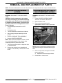
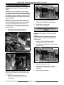
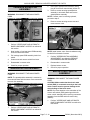
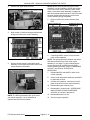
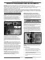
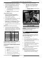
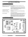
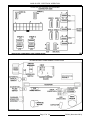
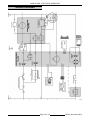
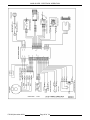
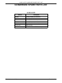
SERVICE MANUAL
SUPPLEMENT
Use this Service Manual Supplement in conjunction
with Service Manual F24569 and Technical Service
Bulletins 1053, 1054, 1064, 1078-A, 1096, 1105, 1113,
and 1146.
SLICER
MODEL
2912B
ML-134123
- NOTICE This Manual is prepared for the use of trained Hobart Service
Technicians and should not be used by those not properly
qualified. If you have attended a Hobart Service School for this
product, you may be qualified to perform all the procedures
described in this manual.
This manual is not intended to be all encompassing. If you have
not attended a Hobart Service School for this product, you should
read, in its entirety, the repair procedure you wish to perform to
determine if you have the necessary tools, instruments and skills
required to perform the procedure. Procedures for which you do
not have the necessary tools, instruments and skills should be
performed by a trained Hobart Service Technician.
Reproduction or other use of this Manual, without the express
written consent of Hobart Corporation, is prohibited.
A Product of Hobart Corporation
TROY, OHIO 45374
F25103 (November 2001)
2912B SLICER
TABLE OF CONTENTS
GENERAL . . . . . . . . . . . . . . . . . . . . . . . . . . . . . . . . . . . . . . . . . . . . . . . . . . . . . . . . . . . . . . . . . . . . . . . . . . . . .
Introduction . . . . . . . . . . . . . . . . . . . . . . . . . . . . . . . . . . . . . . . . . . . . . . . . . . . . . . . . . . . . . . . . . . . . . . . . . .
Overview . . . . . . . . . . . . . . . . . . . . . . . . . . . . . . . . . . . . . . . . . . . . . . . . . . . . . . . . . . . . . . . . . . . . . . . .
Appearance . . . . . . . . . . . . . . . . . . . . . . . . . . . . . . . . . . . . . . . . . . . . . . . . . . . . . . . . . . . . . . . . . . . . . .
Electrical Features . . . . . . . . . . . . . . . . . . . . . . . . . . . . . . . . . . . . . . . . . . . . . . . . . . . . . . . . . . . . . . . . .
Automatic Mode . . . . . . . . . . . . . . . . . . . . . . . . . . . . . . . . . . . . . . . . . . . . . . . . . . . . . . . . . . . . . . . . . . .
Control Board . . . . . . . . . . . . . . . . . . . . . . . . . . . . . . . . . . . . . . . . . . . . . . . . . . . . . . . . . . . . . . . . . . . . .
Tools . . . . . . . . . . . . . . . . . . . . . . . . . . . . . . . . . . . . . . . . . . . . . . . . . . . . . . . . . . . . . . . . . . . . . . . . . . . . . . .
Basic Operation . . . . . . . . . . . . . . . . . . . . . . . . . . . . . . . . . . . . . . . . . . . . . . . . . . . . . . . . . . . . . . . . . . . . . . .
Start Slicer . . . . . . . . . . . . . . . . . . . . . . . . . . . . . . . . . . . . . . . . . . . . . . . . . . . . . . . . . . . . . . . . . . . . . . .
Pause Slicer (Automatic Mode Only) . . . . . . . . . . . . . . . . . . . . . . . . . . . . . . . . . . . . . . . . . . . . . . . . . . .
Changing to Automatic While Operating in Manual Mode . . . . . . . . . . . . . . . . . . . . . . . . . . . . . . . . . . . .
Stop Slicer . . . . . . . . . . . . . . . . . . . . . . . . . . . . . . . . . . . . . . . . . . . . . . . . . . . . . . . . . . . . . . . . . . . . . . .
Returning Carriage Assembly to Home . . . . . . . . . . . . . . . . . . . . . . . . . . . . . . . . . . . . . . . . . . . . . . . . . .
Reference Material . . . . . . . . . . . . . . . . . . . . . . . . . . . . . . . . . . . . . . . . . . . . . . . . . . . . . . . . . . . . . . . . . . . .
3
3
3
3
3
3
3
3
3
4
4
4
4
4
4
REMOVAL AND REPLACEMENT OF PARTS . . . . . . . . . . . . . . . . . . . . . . . . . . . . . . . . . . . . . . . . . . . . . . . . .
Slicer Control Board Access . . . . . . . . . . . . . . . . . . . . . . . . . . . . . . . . . . . . . . . . . . . . . . . . . . . . . . . . . . . . .
Slicer Control Board . . . . . . . . . . . . . . . . . . . . . . . . . . . . . . . . . . . . . . . . . . . . . . . . . . . . . . . . . . . . . . . . . . .
Carriage Motor Relay (CMCR) . . . . . . . . . . . . . . . . . . . . . . . . . . . . . . . . . . . . . . . . . . . . . . . . . . . . . . . . . . . .
Carriage Speed PCB Assembly . . . . . . . . . . . . . . . . . . . . . . . . . . . . . . . . . . . . . . . . . . . . . . . . . . . . . . . . . . .
Speed/Position Assembly . . . . . . . . . . . . . . . . . . . . . . . . . . . . . . . . . . . . . . . . . . . . . . . . . . . . . . . . . . . . . . .
Motor Start Switch Assembly . . . . . . . . . . . . . . . . . . . . . . . . . . . . . . . . . . . . . . . . . . . . . . . . . . . . . . . . . . . . .
5
5
6
6
7
7
7
SERVICE PROCEDURES AND ADJUSTMENTS . . . . . . . . . . . . . . . . . . . . . . . . . . . . . . . . . . . . . . . . . . . . . . . 9
Slicer Control Board LEDs . . . . . . . . . . . . . . . . . . . . . . . . . . . . . . . . . . . . . . . . . . . . . . . . . . . . . . . . . . . . . . . 9
Carriage Speed PCB Assembly . . . . . . . . . . . . . . . . . . . . . . . . . . . . . . . . . . . . . . . . . . . . . . . . . . . . . . . . . . . 9
Red LED Checks . . . . . . . . . . . . . . . . . . . . . . . . . . . . . . . . . . . . . . . . . . . . . . . . . . . . . . . . . . . . . . . . . . 9
Voltage Reading Checks . . . . . . . . . . . . . . . . . . . . . . . . . . . . . . . . . . . . . . . . . . . . . . . . . . . . . . . . . . . 10
Speed/Position Assembly . . . . . . . . . . . . . . . . . . . . . . . . . . . . . . . . . . . . . . . . . . . . . . . . . . . . . . . . . . . . . . 10
Yellow LED Checks . . . . . . . . . . . . . . . . . . . . . . . . . . . . . . . . . . . . . . . . . . . . . . . . . . . . . . . . . . . . . . . 10
Voltage Reading Check . . . . . . . . . . . . . . . . . . . . . . . . . . . . . . . . . . . . . . . . . . . . . . . . . . . . . . . . . . . . 11
Adjustment . . . . . . . . . . . . . . . . . . . . . . . . . . . . . . . . . . . . . . . . . . . . . . . . . . . . . . . . . . . . . . . . . . . . . . 11
Home Switch . . . . . . . . . . . . . . . . . . . . . . . . . . . . . . . . . . . . . . . . . . . . . . . . . . . . . . . . . . . . . . . . . . . . . . . . 12
Red LED Checks . . . . . . . . . . . . . . . . . . . . . . . . . . . . . . . . . . . . . . . . . . . . . . . . . . . . . . . . . . . . . . . . . 12
Continuity Check . . . . . . . . . . . . . . . . . . . . . . . . . . . . . . . . . . . . . . . . . . . . . . . . . . . . . . . . . . . . . . . . . 12
Start/Stop/Pause Switch . . . . . . . . . . . . . . . . . . . . . . . . . . . . . . . . . . . . . . . . . . . . . . . . . . . . . . . . . . . . . . . 12
Red LED Checks . . . . . . . . . . . . . . . . . . . . . . . . . . . . . . . . . . . . . . . . . . . . . . . . . . . . . . . . . . . . . . . . . 12
Voltage Reading Checks . . . . . . . . . . . . . . . . . . . . . . . . . . . . . . . . . . . . . . . . . . . . . . . . . . . . . . . . . . . 13
Interlock Switch (1LS) . . . . . . . . . . . . . . . . . . . . . . . . . . . . . . . . . . . . . . . . . . . . . . . . . . . . . . . . . . . . . . . . . 13
Checks . . . . . . . . . . . . . . . . . . . . . . . . . . . . . . . . . . . . . . . . . . . . . . . . . . . . . . . . . . . . . . . . . . . . . . . . . 13
Automatic/manual Switch (2S) . . . . . . . . . . . . . . . . . . . . . . . . . . . . . . . . . . . . . . . . . . . . . . . . . . . . . . . . . . . 14
Checks . . . . . . . . . . . . . . . . . . . . . . . . . . . . . . . . . . . . . . . . . . . . . . . . . . . . . . . . . . . . . . . . . . . . . . . . . 14
Lamp (1PL) . . . . . . . . . . . . . . . . . . . . . . . . . . . . . . . . . . . . . . . . . . . . . . . . . . . . . . . . . . . . . . . . . . . . . . . . . 14
Carriage Motor . . . . . . . . . . . . . . . . . . . . . . . . . . . . . . . . . . . . . . . . . . . . . . . . . . . . . . . . . . . . . . . . . . . . . . . 15
Checks . . . . . . . . . . . . . . . . . . . . . . . . . . . . . . . . . . . . . . . . . . . . . . . . . . . . . . . . . . . . . . . . . . . . . . . . . 15
ELECTRICAL OPERATION . . . . . . . . . . . . . . . . . . . . . . . . . . . . . . . . . . . . . . . . . . . . . . . . . . . . . . . . . . . . . .
Component Function . . . . . . . . . . . . . . . . . . . . . . . . . . . . . . . . . . . . . . . . . . . . . . . . . . . . . . . . . . . . . . . . . .
Start/Stop/Pause Switch (1S) . . . . . . . . . . . . . . . . . . . . . . . . . . . . . . . . . . . . . . . . . . . . . . . . . . . . . . . .
Carriage Speed PCB Assembly . . . . . . . . . . . . . . . . . . . . . . . . . . . . . . . . . . . . . . . . . . . . . . . . . . . . . .
Speed/Position Assembly . . . . . . . . . . . . . . . . . . . . . . . . . . . . . . . . . . . . . . . . . . . . . . . . . . . . . . . . . . .
Slicer Control Board . . . . . . . . . . . . . . . . . . . . . . . . . . . . . . . . . . . . . . . . . . . . . . . . . . . . . . . . . . . . . . .
Component Layout . . . . . . . . . . . . . . . . . . . . . . . . . . . . . . . . . . . . . . . . . . . . . . . . . . . . . . . . . . . . . . . . . . .
Sequence of Operation . . . . . . . . . . . . . . . . . . . . . . . . . . . . . . . . . . . . . . . . . . . . . . . . . . . . . . . . . . . . . . . .
Manual Sequence of Operation . . . . . . . . . . . . . . . . . . . . . . . . . . . . . . . . . . . . . . . . . . . . . . . . . . . . . .
Conditions . . . . . . . . . . . . . . . . . . . . . . . . . . . . . . . . . . . . . . . . . . . . . . . . . . . . . . . . . . . . . . . . . . . . . .
Automatic Sequence of Operation . . . . . . . . . . . . . . . . . . . . . . . . . . . . . . . . . . . . . . . . . . . . . . . . . . . .
F25103 (November 2001)
Page 2 of 24
16
16
16
16
16
16
16
18
18
18
18
2912B SLICER - GENERAL
Pause Sequence of Operation . . . . . . . . . . . . . . . . . . . . . . . . . . . . . . . . . . . . . . . . . . . . . . . . . . . . . . . 18
Wiring Diagrams . . . . . . . . . . . . . . . . . . . . . . . . . . . . . . . . . . . . . . . . . . . . . . . . . . . . . . . . . . . . . . . . . . . . . 19
TROUBLESHOOTING . . . . . . . . . . . . . . . . . . . . . . . . . . . . . . . . . . . . . . . . . . . . . . . . . . . . . . . . . . . . . . . . . . 21
Manual Slicing . . . . . . . . . . . . . . . . . . . . . . . . . . . . . . . . . . . . . . . . . . . . . . . . . . . . . . . . . . . . . . . . . . . . . . . 21
Automatic Slicing . . . . . . . . . . . . . . . . . . . . . . . . . . . . . . . . . . . . . . . . . . . . . . . . . . . . . . . . . . . . . . . . . . . . . 22
CONDENSED SPARE PARTS LIST . . . . . . . . . . . . . . . . . . . . . . . . . . . . . . . . . . . . . . . . . . . . . . . . . . . . . . . . 24
© Hobart Corporation 2001
GENERAL
Control Board
INTRODUCTION
Overview
The 2912B is a 2000 Series based slicer that
replaces the 2912SC for roast beef specific
customers. Micro Ban technology is featured in all
exposed plastic components.
Appearance
The outside appearance of the 2912B is very similar
to the 2912 with only slight changes.
•
Heavier stainless steel meat grip arm.
•
Start/Stop/Pause and Automatic/Manual labels.
Electrical Features
Control board software controls the slice stroke
speed. The software adjusts the slice stroke speed
according to the load presented to the carriage
assembly at any given time. This feature maintains
a constant carriage speed as the load is lightened.
Also, the carriage return stroke will be faster than
the slice stroke by a proportion determined by the
software.
A feature unique to the 2912B is the use of three
LEDs, (Green - Power, Yellow - Speed/Position, and
Red - Diagnostic). LEDs are used as a diagnostic
tool when troubleshooting the slicer. Information
regarding the LEDs as a troubleshooting aid can be
found in "SERVICE PROCEDURES AND
ADJUSTMENTS".
TOOLS
Electrically, the 2912B features:
•
Slicer circuit board with on-board replaceable
carriage motor relay (CMCR).
•
Enhanced software with start/pause circuitry in
automatic mode.
•
Optical speed/position sensor for carriage
speed control.
•
Loctite 242 - Threads securing bracket sensor.
BASIC OPERATION
In order for the 2912B to operate, certain conditions
must be met before engaging Start/Stop/Pause
switch.
Automatic Mode
•
The 2912B can be started in either Automatic
or Manual mode of operation.
1.
Slicer must be plugged into appropriate power
source.
•
Carriage speed is adjustable (6 speeds).
Carriage movement is monitored by the
speed/position assembly and control board.
2.
Carriage assembly must be in "home" position.
In Automatic mode start-up, the carriage motor
begins driving the carriage assembly at half power
until the control board senses the desired speed,
load presented to the carriage, and carriage position
in relation to home position. Once these factors are
known, the control board sets the carriage motor to
drive the carriage assembly at the correct speed. It
takes two or three carriage stroke cycles to settle
into the correct operating speed.
NOTE: Carriage assembly is in home position when
carriage is pulled nearest to operator controls.
3.
Page 3 of 24
Gauge plate must be opened.
F25103 (November 2001)
2912B SLICER - GENERAL
4.
Pull Start/Stop/Pause switch out fully and
release.
A.
Carriage motor starts.
B.
Carriage assembly moves according to
speed selected.
Stop Slicer
Start Slicer
NOTE: Slicer can be started in either Automatic or
Manual mode.
1.
Pull Start/Stop/Pause switch out fully and
release.
A.
B.
Push Start/Stop/Pause switch in fully.
NOTE: When stopping the slicer in Automatic
mode, the carriage assembly will stop in its present
position unless the Start/Stop/Pause switch is first
pulled OUT and released allowing the carriage
assembly to return to home position.
The carriage assembly must be returned to home
position before slicer can be restarted.
1.
Turn automatic lever to Manual.
1)
2.
Pull carriage assembly to the home position
(nearest operator controls).
Knife motor starts.
Automatic mode.
1)
Knife motor starts.
2)
Carriage motor starts.
REFERENCE MATERIAL
Carriage assembly moves according
to speed selected.
The 2912B can be serviced using 2912 Service
Manual F-24569 for mechanical and adjustment
procedures.
Parts for the 2912B can be ordered using the 2912B
Catalog of Replacement Parts F-43041.
Information on components and parts unique to the
2912B can be found in this Service Manual
Supplement.
Pause Slicer (Automatic Mode Only)
2.
2.
Manual mode.
3)
Pull Start/Stop/Pause switch out fully and
release.
A.
Close gauge plate.
Returning Carriage Assembly to Home
NOTE: It may take two or three slice strokes for the
carriage motor to settle into the desired operating
speed.
1.
1.
Carriage assembly will finish the current
slice cycle, slow on the return stroke, and
stop in home position.
To resume slicing, pull Start/Stop/Pause switch
out fully and release.
A.
Carriage assembly will start moving at 1/2
power until control board adjusts for
desired speed.
Changing to Automatic While Operating in
Manual Mode
1.
Slicer operating in Manual mode. Carriage
assembly in home position.
NOTE: If carriage assembly is not in home position
when automatic knob and lever is set to Automatic
and Start/Stop/Pause switch is pulled out, knife
motor will shut off.
2.
Turn automatic lever to Automatic.
3.
Set carriage speed control switch to desired
speed.
F25103 (November 2001)
Page 4 of 24
2912B SLICER - REMOVAL AND REPLACEMENT OF PARTS
REMOVAL AND REPLACEMENT OF PARTS
NOTE: This section addresses the removal and replacement of components that are unique to the 2912B slicer.
SLICER CONTROL BOARD
ACCESS
UPPER BASE AND AUTOMATIC
BASE COMPONENT ACCESS
WARNING: DISCONNECT THE MAIN POWER
CORD.
WARNING: DISCONNECT THE MAIN POWER
CORD.
CAUTION: Certain components in this system
are subject to damage by electrostatic discharge
during field repairs. A field service grounding kit
is available to prevent damage. The field service
grounding kit must be used anytime the control
board is handled.
1.
Perform "SLICER CONTROL BOARD
ACCESS" as outlined in this section.
2.
Remove bottom cover.
3.
Remove the screws securing the
speed/position sensor P-clips to upper base.
1.
Push Start/Stop/Pause switch in to OFF
position.
2.
Close gauge plate.
3.
Turn the automatic knob and lever to Manual.
4.
Move carriage transport assembly to home
position.
5.
Remove "CARRIAGE TRAY ASSEMBLY".
6.
Remove "KNIFE SHARPENER".
NOTE: Make certain that sharpener handle is folded
in to avoid breaking handle. Use a cloth or other
cushioning material to protect slicer finish.
7.
Turn slicer up and rest slicer on sharpener side
of automatic base.
8.
Remove the electrical cover assembly and
position cover assembly to access slicer control
board.
NOTE: Remove slicer feet as required to access
cap screws securing the automatic base to upper
base.
4.
Remove cap screws securing the automatic
base to upper base.
A.
5.
Page 5 of 24
Separate automatic and upper bases.
Reassemble in reverse order.
F25103 (November 2001)
2912B SLICER - REMOVAL AND REPLACEMENT OF PARTS
SLICER CONTROL BOARD
WARNING: DISCONNECT THE MAIN POWER
CORD.
CAUTION: Certain components in this system
are subject to damage by electrostatic discharge
during field repairs. A field service grounding kit
is available to prevent damage. The field service
grounding kit must be used anytime the control
board is handled.
NOTE: All electrical connections are made through
the slicer control board. The control board also
houses a replaceable carriage motor relay (CMCR)
and a set of three LEDs that can be used as a
troubleshooting aid. The carriage motor relay, plug
(*P), and junction (J*) locations are shown in the
photos that follow.
1.
3.
Remove nuts securing control board to
electrical cover and remove control board.
4.
Reassemble in reverse order.
5.
Check for proper operation.
CARRIAGE MOTOR RELAY
(CMCR)
Note locations and unplug all electrical
connections on the slicer control board.
WARNING: DISCONNECT THE MAIN POWER
CORD.
CAUTION: Exercise care when removing the
carriage motor relay to avoid damage to the
control board.
NOTE: The carriage motor relay can be difficult to
remove. Use care when removing relay from slicer
control board.
2.
1.
Perform "SLICER CONTROL BOARD
ACCESS" as outlined in this section.
2.
Carefully pry carriage motor relay from control
board terminals.
3.
Replace carriage motor relay.
4.
Reassemble in reverse order, "SLICER
CONTROL BOARD ACCESS" as outlined in
this section.
5.
Check for proper operation.
Remove "CARRIAGE MOTOR RELAY
(CMCR)" if it is to be reused on new slicer
control board.
F25103 (November 2001)
Page 6 of 24
2912B SLICER - REMOVAL AND REPLACEMENT OF PARTS
CARRIAGE SPEED PCB
ASSEMBLY
WARNING: DISCONNECT THE MAIN POWER
CORD.
2.
Disconnect speed/position assembly wiring
plug 6P from slicer control board junction J6.
3.
Remove screws securing speed/position
assembly to automatic base and remove
speed/position assembly.
NOTE: If sensor vane is not being replaced,
proceed to step 5.
4.
1.
Perform "UPPER BASE AND AUTOMATIC
BASE COMPONENT ACCESS" as outlined in
this section.
2.
Note location of carriage speed PCB assembly
wires and disconnect wires.
3.
Pull carriage speed PCB assembly knob from
switch.
4.
Unscrew nut and remove switch from base.
5.
6.
Remove screws securing sensor vane and
remove sensor vane.
NOTE: Install sensor vane. Secure hardware using
Loctite 242 on threads of screws.
5.
Perform "SPEED/POSITION ASSEMBLY
ADJUSTMENT" as outlined in "SERVICE
PROCEDURES AND ADJUSTMENTS".
Reassemble in reverse order.
6.
Reassemble in reverse order.
Check for proper operation.
7.
Replace bottom covers.
8.
Check for proper operation.
SPEED/POSITION ASSEMBLY
MOTOR START SWITCH
ASSEMBLY
WARNING: DISCONNECT THE MAIN POWER
CORD.
NOTE: The speed/position assembly is mounted to
the automatic base with the sensor vane mounted to
the main link assembly.
WARNING: DISCONNECT THE MAIN POWER
CORD.
CAUTION: Make certain that the electric start
switch (ESS) is connected correctly to the knife
motor control board to prevent damage to the
start windings of the knife motor.
NOTE: Pay close attention to the orientation of the
electric start switch (ESS) spade lugs with knife
motor control assembly when removing connection
assembly from the ESS and knife motor relay
(KMCR).
1.
1.
Perform "UPPER BASE AND AUTOMATIC
BASE COMPONENT ACCESS" as outlined in
this section.
Perform "UPPER BASE AND AUTOMATIC
BASE COMPONENT ACCESS" as outlined in
this section.
Page 7 of 24
F25103 (November 2001)
2912B SLICER - REMOVAL AND REPLACEMENT OF PARTS
2.
Remove the upper electrical cover.
NOTE: Before removing the knife motor control
assembly, note pin orientation of ESS with relation
to the knife motor control assembly. Make certain
that the motor start switch assembly is installed so
that wider spaced spade terminals of the ESS match
the wider spaced terminal fittings on knife motor
control assembly during reassembly.
5.
3.
Remove knife motor control assembly from
ESS.
Note location of electrical wiring and disconnect
wiring from knife motor control assembly.
KNIFE MOTOR CONTROL ASSEMBLY
6.
KNIFE MOTOR CONTROL ASSEMBLY
4.
Remove screws securing motor start switch
assembly to slicer base and remove motor start
switch assembly with KMCR.
If replacing KMCR, remove it from the knife
motor control assembly.
NOTE: The spacing difference between the narrow
and wide terminals on the knife motor control
assembly is very slight. To help in identifying the
correct positioning of the ESS and knife motor
control assembly terminals, refer to "COMPONENT
LAYOUT" as outlined in "ELECTRICAL
OPERATION".
7.
Reassemble ESS and KMCR to knife motor
control assembly.
8.
Secure motor start switch assembly and KMCR
to upper base of slicer.
9.
Connect wiring harness, motor wires, and AC
power wires to knife motor control assembly.
10. Reassemble upper electrical cover.
11. Reassemble in reverse order, "UPPER BASE
AND AUTOMATIC BASE COMPONENT
ACCESS" as outlined in this section.
NOTE: The ESS and bracket make up the motor
start switch assembly. It is not necessary to
separate the ESS from the bracket.
F25103 (November 2001)
12. Reassemble bottom covers.
13. Check for proper operation.
Page 8 of 24
2912B SLICER SERVICE PROCEDURES AND ADJUSTMENTS
SERVICE PROCEDURES AND ADJUSTMENTS
WARNING: CERTAIN PROCEDURES IN THIS SECTION REQUIRE ELECTRICAL TEST OR
MEASUREMENTS WHILE POWER IS APPLIED TO THE MACHINE. EXERCISE EXTREME CAUTION AT ALL
TIMES. IF TEST POINTS ARE NOT EASILY ACCESSIBLE, DISCONNECT POWER, ATTACH TEST
EQUIPMENT AND REAPPLY POWER TO TEST.
CAUTION: Certain components in this system are subject to damage by electrostatic discharge during
field repairs. A field service grounding kit is available to prevent damage. The field service grounding kit
must be used anytime the control board is handled.
SLICER CONTROL BOARD LEDS
NOTE: The slicer control board LEDs are located on
the right side of machine, under the carriage
transport when transport is in home position, and
underneath the slicer. The three LEDs can be
viewed through three holes in the bottom electrical
cover.
NOTE: When gauge plate is closed and the
Start/Stop/Pause switch is pulled out half way or
fully, Red LED will flash three times then return to
the 1 second rate. Under a heavy load and at a high
speed setting, the Red LED may flash or go out.
This happens only when full power is being applied
to the carriage motor.
CARRIAGE SPEED PCB
ASSEMBLY (DC VOLTAGE)
NOTE: The carriage speed PCB assembly can be
checked either by observing the flash pattern of the
Red LED, or by voltage readings.
The carriage speed PCB assembly is a six position
switch. Any change to the carriage speed control
knob position will change the resistive value of the
circuit. This change in resistance results in either a
rise or fall of DC voltage across the carriage speed
switch terminals.
Green LED - Power LED that indicates 5 VDC is
present for slicer control board electronic
component operation. The Green LED is ON
whenever the Start/Stop/Pause switch is in the run
position (Start/Stop/Pause switch pulled half way
out).
Yellow LED - Driven by the optical sensor of the
speed/position assembly and the sensor vane. The
Yellow LED flashes at a variable rate depending on
the speed of the carriage transport assembly.
Essentially, the Yellow LED is ON when the sensor
vane blocks the optical sensor light, and OFF when
the light from the optical sensor is allowed to pass
through the sensor vane. When the carriage drive
linkage is in home position the sensor vane will
block the optical sensor light.
Red LED - Diagnostic LED that flashes at a
1 second rate when Start/Stop/Pause switch is
pulled half way out. Red LED is ON constantly
whenever knife motor is running.
NOTE: The speed control switch can be checked in
manual or automatic mode without the knife motor
running.
Red LED Checks
1.
Place carriage assembly in home position.
2.
Place reflective material (mirror or clean putty
knife) under slicer to observe the LEDs.
3.
Turn carriage speed control switch to the LOW
position, fully counterclockwise.
4.
Pull Start/Stop/Pause switch out half way to run
position.
Page 9 of 24
F25103 (November 2001)
2912B SLICER SERVICE PROCEDURES AND ADJUSTMENTS
5.
Verify that the Green LED is ON constantly,
and the Red LED is flashing at a 1 second rate.
6.
Turn the carriage speed control switch one
position clockwise while observing the flash
pattern of the Red LED.
With meter on DC setting, place COM
meter lead on pin J7-1 and Red meter
lead on pin J7-2 and observe meter
reading.
A.
Three quick flashes then a return to the
1 second rate indicates that the switch is
operating normally.
1)
B.
Repeat the Red LED test for all switch
positions.
NOTE: Knife motor should not be running.
E.
Measured voltage across these points
should be 5 VDC.
Voltage Reading Checks
1.
Perform "SLICER CONTROL BOARD
ACCESS" as outlined in "REMOVAL AND
REPLACEMENT OF PARTS".
2.
Connect slicer to power source.
3.
Turn carriage speed PCB assembly knob to the
LOW position (fully counterclockwise).
4.
With the meter on DC setting, place COM
meter lead on J7-1 and Red lead on J7-2 while
2P is connected to J7 on the control board.
5.
Pull Start/Stop/Pause switch out half way to run
position.
SPEED/POSITION ASSEMBLY
(DC VOLTAGE)
NOTE: Knife motor should not be running.
6.
7.
Verify that the Green LED is ON constantly,
and the Red LED is flashing at a 1 second rate.
Observe meter reading and refer to table below
for each position/voltage value.
NOTE: A flashing Yellow LED in automatic mode
indicates a functioning speed/position assembly.
Knob Position DC Voltage
Ohms
1
5.0 - 0.5V Open ( )
(LOW, CCW)
2
4.0 ± 0.5V
8.87k 3
3.0 ± 0.5V
3.27k 4
2.0 ± 0.5V
1.47k 5
1.0 ± 0.5V
560 6
0.0 + 0.5V
0.0 (HI, CW)
Yellow LED Checks
The carriage speed PCB assembly is checked by
observing the flashing rate of the Yellow (center)
LED, and by voltage readings.
NOTE: A change of voltage for each switch position
indicates a normally functioning switch.
To check resistance, disconnect power to slicer and
unplug 2P from J-7. Measure resistance across 2P
terminals 1/2.
8.
If voltage reading is 0.0 VDC or near zero at
slowest setting (full CCW):
A.
Push Start/Stop/Pause switch IN to turn
power off.
B.
Remove meter leads from J7-1 and J7-2.
C.
Unplug 2P from J7 on control board.
D.
Pull Start/Stop/Pause switch out half way.
F25103 (November 2001)
WARNING: THE SLICER KNIFE IS VERY SHARP.
EXERCISE EXTREME CAUTION WHEN
WORKING NEAR THE KNIFE.
1.
Open gauge plate.
2.
Place carriage assembly in home position.
3.
Turn carriage speed control switch to the LOW
position (fully counterclockwise).
4.
Turn automatic lever to Automatic.
5.
Place reflective material (mirror or clean putty
knife) under slicer to observe the Yellow
(center) LED.
6.
Turn slicer ON by pulling the Start/Stop/Pause
switch out fully and releasing.
NOTE: The knife motor should be running and
carriage assembly should be moving.
7.
Page 10 of 24
Verify that the Green and Red LEDs are ON
constantly and the Yellow LED is flashing.
2912B SLICER SERVICE PROCEDURES AND ADJUSTMENTS
NOTE: The Yellow LED will flash at a variable rate
in relation to the speed at which the carriage
assembly is moving.
Placing a load on the carriage assembly (holding
onto the carriage handle) will slow the carriage
assembly movement enough to see a change in the
Yellow LED flash rate.
EXAMPLE: LOW speed selected and a load on the
carriage assembly will result in a noticeable on/off
LED flashing rate. However, with HI speed selected
and no load on carriage assembly, the Yellow LED
will be flashing rapidly - flickering, almost appearing
to be on constantly.
Voltage Reading Check
1.
Perform "SLICER CONTROL BOARD
ACCESS" as outlined in "REMOVAL AND
REPLACEMENT OF PARTS".
NOTE: Sensor vane is properly adjusted when the
sensor vane travels in the approximate middle of
the optical sensor for the entire travel path of the
carriage transport assembly. Pay close attention to
the ends of sensor vane as optical sensor contact
(interference) is most likely to occur at these points.
2.
Unplug plug 6P from junction J6.
3.
3.
Connect slicer into power source.
4.
Pull Start/Stop/Pause switch out half way.
5.
With meter on DC setting, place COM meter
lead on J6-2 and RED meter lead on J6-1.
6.
Verify that 5VDC is present across terminals
J6-1 and J6-2.
NOTE: If the Yellow LED does not light at all, check
slicer control board J6 output voltage.
Loosen screws securing sensor vane to main
link assembly.
NOTE: Apply Loctite 242 to sensor vane screws
before adjusting and securing sensor vane to main
link assembly.
A.
Adjustment
WARNING: DISCONNECT THE MAIN POWER
CORD.
Adjust sensor vane/optical sensor
clearance by reforming the sensor vane or
by moving sensor vane in or out to
position sensor vane within the
approximate center of the optical sensor
for the entire range of main link travel.
CAUTION: The optical sensor of the
speed/position assembly can be damaged if the
sensor vane is not first properly aligned with the
speed/position assembly before operating
slicer.
1.
Perform "UPPER BASE AND AUTOMATIC
BASE COMPONENT ACCESS" as outlined in
"REMOVAL AND REPLACEMENT OF
PARTS".
2.
Disconnect motor drive link assembly from
main link assembly and carriage drive motor.
NOTE: When viewing the sensor vane through the
inspection holes, the sensor vane should pass under
the center of both inspection holes.
B.
Page 11 of 24
Move main link assembly back and forth
the full travel range while observing the
sensor vane/optical sensor clearance
through the inspection holes.
F25103 (November 2001)
2912B SLICER SERVICE PROCEDURES AND ADJUSTMENTS
5.
Place reflective material (mirror or clean putty
knife) under slicer to observe the Red LED.
6.
Pull Start/Stop/Pause switch out half way to run
position.
NOTE: Knife motor should not be running.
4.
Tighten sensor vane screws and recheck
sensor vane adjustment. Readjust if necessary.
7.
Verify that the Green LED is ON constantly and
the Red LED is flashing at a 1 second rate.
8.
Move carriage assembly away from home
position while observing the Red LED flash
pattern.
NOTE: Three quick flashes of the Red LED then a
return back to the 1 second flash rate indicates that
the home position switch is operating.
NOTE: Make certain that plug 6P is connected to
junction J6 on the control board.
9.
Return carriage assembly to home position
while observing the Red LED flash pattern.
5.
Position slicer control board to view LEDs.
NOTE: The Red LED should repeat the 3 quick
flashes then return to a 1 second flash rate.
6.
Connect slicer into power source.
7.
Pull Start/Stop/Pause switch out half way to run
position.
8.
Verify that the Green LED is ON constantly.
9.
Manually move main link assembly through full
travel range.
Continuity Check
10. Verify that the Yellow LED flashes ON and
OFF as sensor vane passes through optical
sensor of speed/position assembly.
WARNING: DISCONNECT THE MAIN POWER
CORD.
1.
Perform "SLICER CONTROL BOARD
ACCESS" as outlined in "REMOVAL AND
REPLACEMENT OF PARTS".
2.
Disconnect plug 1P from junction J1 on the
control board.
3.
11. Disconnect power to slicer.
With meter set to resistance (), place meter
leads across 1P2-9 and 1P2-10.
12. Reconnect motor drive link assembly to main
link assembly.
A.
13. Reassemble in reverse order "UPPER BASE
AND AUTOMATIC BASE COMPONENT
ACCESS" as outlined in "REMOVAL AND
REPLACEMENT OF PARTS".
B.
A.
In home position.
1)
Move carriage assembly away from home
position.
1)
Reassemble bottom covers.
14. Check for proper operation.
Resistance reading should be 0.0
ohms.
Resistance reading should be infinite
resistance (open circuit).
START/STOP/PAUSE SWITCH
(AC VOLTAGE)
HOME SWITCH
NOTE: The home switch can be checked either by
observing the flash pattern of the Red LED, or by a
continuity check.
Red LED Checks
NOTE: A change in the Red LED flash pattern
indicates a functioning home switch.
NOTE: Both start/pause and run positions of the
Start/Stop/Pause switch can be checked either by
observing the flash pattern of the Red LED, or by
voltage readings.
Red LED Checks
1.
Close gauge plate.
NOTE: A change in the Red LED flash pattern
indicates a functioning Start/Stop/Pause switch.
2.
Place carriage assembly in home position.
1.
Close gauge plate.
3.
Push Start/Stop/Pause switch in fully to OFF
position.
2.
Place carriage assembly in home position.
3.
4.
Turn automatic lever to Manual.
Push Start/Stop/Pause switch in fully to OFF
position.
F25103 (November 2001)
Page 12 of 24
2912B SLICER SERVICE PROCEDURES AND ADJUSTMENTS
4.
Place reflective material (mirror or clean putty
knife) under slicer to observe the Red LED.
5.
Observe the LEDs while pulling
Start/Stop/Pause switch out half way to run
position.
6.
Verify that the Green LED is ON constantly and
the Red LED flashed 3 times quickly then
changed to flashing at a 1 second rate.
B.
Start/Stop/Pause switch pulled out fully
and held out (contacts closed). Measured
voltage across J1-5 and J1-1 should be
the line voltage (120 VAC).
INTERLOCK SWITCH (1LS)
NOTE: Knife motor will continue to run as long as
Start/Stop/Pause switch is held out fully.
7.
Pull Start/Stop/Pause switch out fully and
release while observing the LEDs.
8.
Verify that the Red LED flash pattern changed
to three quick flashes and then returned to the
1 second flash rate.
WARNING: DISCONNECT THE MAIN POWER
CORD.
WARNING: THE SLICER KNIFE IS VERY SHARP.
EXERCISE EXTREME CAUTION WHEN
WORKING NEAR THE KNIFE.
NOTE: The interlock switch cannot be checked
using the slicer control board LEDs. Because of
slicer control board circuitry, a continuity check is
used to check the interlock switch.
Voltage Reading Checks
Checks
1.
Turn index knob to below "0" position (closed
position).
1.
2.
Perform "SLICER CONTROL BOARD
ACCESS" as outlined in "REMOVAL AND
REPLACEMENT OF PARTS".
Perform "SLICER CONTROL BOARD
ACCESS" as outlined in "REMOVAL AND
REPLACEMENT OF PARTS".
2.
Disconnect plug 1P from junction J1.
3.
3.
Connect slicer to power source.
4.
Verify that line voltage is present to slicer
control board terminals J4/J5 (Hot) and J2/J3
(Neutral).
On-Off Section of Switch (N.O. Contacts)
1.
2.
4.
Turn index knob counterclockwise to open
gauge plate while observing meter reading.
5.
Measure resistance.
With meter on AC setting, place COM meter
lead on terminal J1-5 (Neutral) and Red on
J1-3 while plug 1P is connected to J1.
A.
A.
B.
Measured voltage should be the line
voltage (120VAC).
Gauge plate open.
1)
Resistance should be 0.0 ohms.
Gauge plate closed.
1)
Move Red meter lead to J1-4.
A.
3.
With meter set to measure resistance (),
place meter leads across terminals 1P-7 and
1P-8.
Resistance reading should be infinite
resistance (open circuit).
Measured voltage should be
approximately 0.0 VAC.
Pull Start/Stop/Pause switch out half way to the
run position (1S contacts 1/4 closed).
A.
Measured voltage across J1-5 and J1-4
should be the line voltage (120VAC).
Start/Pause Section of Switch (Momentary)
1.
With meter on AC setting, place meter lead
across terminals J1-5 (Neutral) and J1-1 while
plug 1P is connected to J1.
2.
Measure voltage.
A.
Start/Stop/Pause switch in run (half way
out) position. Measured voltage across
J1-5 and J1-1 should be approximately
0.0 VAC.
NOTE: Knife motor will continue to run as long as
Start/Stop/Pause switch is held out fully.
Page 13 of 24
F25103 (November 2001)
2912B SLICER SERVICE PROCEDURES AND ADJUSTMENTS
AUTOMATIC/MANUAL SWITCH
(2S)
LAMP (1PL) - (AC VOLTAGE)
WARNING: THE SLICER KNIFE IS VERY SHARP.
EXERCISE EXTREME CAUTION WHEN
WORKING NEAR THE KNIFE.
WARNING: DISCONNECT THE MAIN POWER
CORD.
NOTE: The automatic/manual switch (2S) is a
SPDT switch with J7-5 being the common terminal.
This switch cannot be checked using the slicer
control board LEDs. Due to the slicer control board
circuitry, switch (2S) is checked by making a
continuity check.
1.
Perform "SLICER CONTROL BOARD
ACCESS" as outlined in "REMOVAL AND
REPLACEMENT OF PARTS".
2.
Open gauge plate.
3.
With meter on AC setting, place meter leads
across J1-5 and J1-6 while 1P is connected to
J1.
4.
Connect slicer to power source.
5.
Pull Start/Stop/Pause switch out fully and
release.
Checks
1.
Perform "SLICER CONTROL BOARD
ACCESS" as outlined in "REMOVAL AND
REPLACEMENT OF PARTS".
2.
Reinstall carriage assembly.
3.
Set meter to resistance () to check continuity.
NOTE: Knife motor should be running.
6.
Testing N.O. Contacts
4.
Automatic knob and lever set to Manual.
5.
Unplug 2P from J7.
6.
Place meter leads across 2P-5 and 2P-4.
A.
Resistance should be 0.0 ohms.
B.
Keeping meter leads on 2P-5 and 2P-4,
set automatic knob and lever to
Automatic.
1)
Resistance across 2P terminals 5/4
should be infinite resistance (open
circuit).
Testing N.C. Contacts
7.
Set automatic lever to Automatic.
8.
Place meter leads across 2P-5 and 2P-3.
A.
Resistance should be 0.0 ohms.
B.
Keeping meter leads on 2P-5 and 2P-3,
set automatic lever to Manual.
1)
Resistance across 2P terminals 5/3
should be infinite resistance (open
circuit).
F25103 (November 2001)
Page 14 of 24
Measured output voltage should be the line
voltage (120 VAC).
2912B SLICER SERVICE PROCEDURES AND ADJUSTMENTS
CARRIAGE MOTOR
(DC VOLTAGE)
WARNING: THE SLICER KNIFE IS VERY SHARP.
EXERCISE EXTREME CAUTION WHEN
WORKING NEAR THE KNIFE.
NOTE: Output voltage to carriage motor varies with
carriage speed selected. Voltage to carriage motor
is lowest when speed select knob is at the LOW
setting (counterclockwise) and highest with speed
select knob set to HI setting (clockwise).
Checks
1.
Perform "SLICER CONTROL BOARD
ACCESS" as outlined in "REMOVAL AND
REPLACEMENT OF PARTS".
2.
Open gauge plate.
3.
Set automatic lever to Automatic.
4.
With meter on DC setting, place COM meter
lead on J7-6 and RED meter lead on J7-7 while
2P is connected to J7.
5.
Connect slicer to power source.
6.
Pull Start/Stop/Pause switch out fully and
release to start slicer in automatic mode of
operation.
7.
Measure carriage motor voltage.
A.
B.
If carriage assembly does not move and
measured voltage is within the range of
50VDC to +120VDC, check:
1)
Motor windings.
2)
Motor brushes.
3)
Related wiring.
If measured voltage is approximately
0.0 VDC:
1)
With meter set on AC, place COM
lead on J1-5 and RED lead on
J7-8. Measure voltage.
a.
If 120VAC is present, slicer
control board has malfunction.
b.
If 120VAC is not present, check
CMCR or circuit breaker.
Page 15 of 24
F25103 (November 2001)
2912B SLICER - ELECTRICAL OPERATION
ELECTRICAL OPERATION
COMPONENT FUNCTION
NOTE: Only features and components unique to the 2912B slicer are listed in this supplement. For a full
component function list, refer to the 2912 Service Manual.
Start/Stop/Pause Switch (1S) . . . . .
Three position switch which controls the electrical power to two slicer
control board triacs. Motor starts when operational conditions are met
and the Start/Stop/Pause switch is pulled fully out. A spring mechanism,
internal to the Start/Stop/Pause switch, will return the Start/Stop/Pause
switch to the run position when the knob is released.
Carriage Speed PCB Assembly . . . Selects speed of carriage speed motor.
Speed/Position Assembly . . . . . . . .
Monitor for speed and position of the carriage assembly’s automatic
drive linkage.
Knife Motor Control Assembly . . . .
Connection board between the knife motor relay, electric start switch,
and wiring (motor and harness).
Slicer Control Board . . . . . . . . . . . .
Controls automatic and manual electrical operations of the slicer through
the mircocontroller. Determines speed and position of the carriage
assembly in automatic mode. Monitors and reports conditions of control
board voltage and carriage speed/position in automatic mode of
operation through the use of Green and Yellow LEDs. On board Red
diagnostic LED displays functionality of carriage speed PCB assembly,
Start/Stop/Pause switch, and home switch by using a flash code.
COMPONENT LAYOUT
F25103 (November 2001)
Page 16 of 24
2912B SLICER - ELECTRICAL OPERATION
Page 17 of 24
F25103 (November 2001)
2912B SLICER - ELECTRICAL OPERATION
B.
SEQUENCE OF OPERATION
KMCR - Knife motor control relay.
CMCR - Carriage motor control relay.
Manual Sequence of Operation
1. Conditions
A. Correct voltage supplied to slicer.
B. Automatic knob and lever in Manual
position.
1) 2LS N.O. contacts closed.
C. Carriage tray assembly in home position.
1) Home Switch N.O. contacts closed.
D. Circuit breaker (1 CB) operating normally
(contacts closed).
E. Gauge plate closed.
1) Interlock switch 1LS contacts open.
F. Start/Stop/Pause switch in OFF position
(Start/Stop/Pause switch pushed in fully).
1) 1S N.O. contacts 1/4 and 1S N.O.
momentary contacts 2/3 are closed.
2. Open gauge plate.
A. Interlock switch 1LS contacts close.
3. Start/Stop/Pause switch pulled out fully to start
position.
A. 1S N.O. contacts 1/4 and 1S N.O.
momentary contacts 2/3 close.
B. Home triac gated ON.
1) KMCR coil energizes.
a. KMCR N.O. contacts 8/6 close.
b. KMCR N.O. contacts 2/4 close.
2) Pilot light energized.
C. AUTO off triac gated ON.
1) Knife motor latching circuit energized.
D. ESS energized.
1) Knife motor operates.
4. Start/Stop/Pause switch (1S) is released to run
(half way out) position.
A. 1S momentary N.O. contacts 2/3 open.
1) Home triac de-energizes.
5. Knife motor operates through latching circuit
until:
A. Start/Stop/Pause switch (1S) is pushed in
to OFF position.
1) 1S N.O. contacts 1/4 open.
B. Gauge plate is closed
1) Interlock switch (1LS) is open.
Automatic Sequence of Operation
1. Conditions same as manual.
2. Automatic knob and lever set to Automatic.
A. 2LS C/N.C. contacts closed.
3. Gauge plate opened.
A. Interlock 1LS N.C./C closed.
4. Start/Stop/Pause switch pulled out fully to start
position.
A. 1S N.O. contacts 1/4 and momentary
contacts 2/3 close.
F25103 (November 2001)
Home triac gated ON.
1) CMCR energized.
a. N.O. contacts 2/4 close.
b. N.O. contacts 6/8 close.
2) KMCR energizes.
a. N.O. contacts 8/6 close.
b. N.O. contacts 2/4 close.
3) Pilot light energizes.
C. Automatic off triac gates ON.
1) Latching circuit to KMCR energizes.
D. ESS energized.
1) Knife motor operates.
E. Bridge rectifier supplies DC to carriage
motor.
F. Carriage speed triac gated ON - controls
DC voltage to carriage motor.
5. Start/Stop/Pause switch (1S) is released to run
(half way out) position.
A. 1S momentary N.O. contacts 2/3 open.
1) Home triac gated off.
6. Knife and carriage motor operate until:
A. Start/Stop/Pause switch (1S) is pushed in
to OFF position.
1) 1S N.O. contacts 1/4 open.
B. Gauge plate is closed.
1) 1LS NC/C contacts open.
C. Circuit Breaker (1CB) opens.
1) Carriage motor stops running.
2) Knife motor continues to run.
D. Start/Stop/Pause switch (1S) is pulled out
fully to initiate pause sequence.
Pause Sequence of Operation
1. Condition - Slicer operating in Automatic mode.
2. Start/Stop/Pause switch (1S) is pulled out fully
and released while slicer is operating in
automatic mode.
A. Slicer control board slows carriage motor
on return slice stroke preparing to stop in
home position.
B. Slicer control board gates AUTO off triac
to off condition.
C. KMCR coil de-energizes.
1) KMCR N.O. contacts 2/4 and 6/8
open.
a. KMCR and CMCR circuits
unlatch and knife motor stops
running respectively.
D. CMCR coil de-energizes.
1) CMCR N.O. contacts 6/8 and 2/4
open.
a. Carriage motor stops.
3. Start/Stop/Pause switch (1S) is pulled out fully
and released.
A. Repeats steps 2 through 5 of
"AUTOMATIC SEQUENCE OF
OPERATION".
Page 18 of 24
2912B SLICER - ELECTRICAL OPERATION
WIRING DIAGRAMS
Page 19 of 24
F25103 (November 2001)
2912B SLICER - ELECTRICAL OPERATION
F25103 (November 2001)
Page 20 of 24
2912B SLICER TROUBLESHOOTING
TROUBLESHOOTING
MANUAL SLICING
1.
Slicer connected to voltage specified on data plate.
2.
Gauge plate opened.
3.
Carriage assembly is in home position.
4.
Automatic/Manual switch set to Manual.
5.
Start/Stop/Pause switch pulled out fully and released.
SYMPTOM
Knife motor does not run. (Pilot light does not light).
1.
NOTE: Knife motor may hum if certain components are 2.
inoperative.
3.
Knife motor does not run. (Pilot light lit).
Knife motor starts slow or starts backwards.
Start/Stop/Pause switch (1S) inoperative.
Home position switch open.
4.
Magnet weak or missing. (Carriage transport).
5.
Auto/Man switch (2LS) inoperative.
6.
KMCR inoperative.
7.
Knife motor control assembly malfunction.
8.
1.
Slicer control board malfunction.
Electronic start switch malfunction (motor may
hum).
NOTE: Knife motor may hum if certain components are
2.
inoperative.
Knife motor will only run with Start/Stop/Pause switch
held out fully.
POSSIBLE CAUSE
No power to slicer.
KMCR inoperative.
3.
Capacitor inoperative (motor may hum).
4.
1.
Knife motor is inoperative (motor may hum).
Gauge plate not open.
2.
Gauge plate interlock switch (1LS) inoperative.
3.
Auto/Man switch (2S) is inoperative.
4.
KMCR contacts 2/4 inoperative.
1.
Electronic start switch malfunction.
2.
Capacitor inoperative.
Page 21 of 24
F25103 (November 2001)
2912B SLICER TROUBLESHOOTING
AUTOMATIC SLICING
NOTE: Make sure that the knife motor runs in manual slice mode before proceeding. If not, trouble shoot from
manual slicing chart.
1.
Slicer connected to voltage specified on data plate.
2.
Gauge plate opened24.
3.
Carriage assembly is in home position.
4.
Automatic knob and lever set to Automatic.
5.
Start/Stop/Pause switch pulled out fully and released.
SYMPTOM
Knife motor does not run in Automatic.
Knife motor runs.
1.
1.
POSSIBLE CAUSE
Auto/Man switch (2LS) inoperative.
Circuit breaker (1CB) tripped.
(Carriage drive motor does not operate).
2.
Auto/Man (2LS) inoperative.
3.
CMCR inoperative.
4.
Carriage drive motor inoperative.
Cannot change speed of carriage drive motor.
5.
1.
Slicer control board malfunction.
Carriage speed PCB assembly inoperative.
(Pause feature operates normally).
Cannot change speed of carriage drive motor.
2.
1.
Slicer control board malfunction.
Speed/Position assembly inoperative.
(Pause feature does not operate normally. Carriage
assembly at times stops away from home position).
2.
Sensor vane blocked or missing.
3.
Slicer control board malfunction.
F25103 (November 2001)
Page 22 of 24
2912B SLICER
- NOTES -
Page 23 of 24
F25103 (November 2001)
2912B SLICER CONDENSED SPARE PARTS LIST
CONDENSED SPARE PARTS LIST
2912B SLICER
Part No.
Description
873630
Carriage Speed PCB Assembly
873633
Slicer Control PCB Board
873643
Speed/Position Assembly
873638
Sensor Vane
438929
Motor Start Switch Assembly
87714 -42-1
Relay (2 pole)
873635
Knife Motor Control PCB Assembly
F25103 (November 2001)
Printed in U.S.A.