1
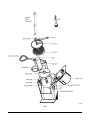
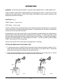
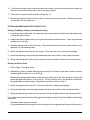
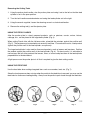
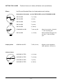
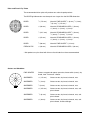
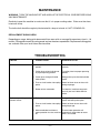
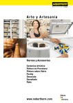
FOOD PROCESSORS
FP350 FOOD PROCESSOR
MODEL
FP350
ML-104586
701 S. RIDGE AVENUE
TROY, OHIO 45374-0001
937 332-3000
www.hobartcorp.com
FORM 19353 Rev. D (Oct. 2000)
TABLE OF CONTENTS
GENERAL . . . . . . . . . . . . . . . . . . . . . . . . . . . . . . . . . . . . . . . . . . . . . . . . 3
INSTALLATION . . . . . . . . . . . . . . . . . . . . . . . . . . . . . . . . . . . . . . . . . . . 3
Unpacking . . . . . . . . . . . . . . . . . . . . . . . . . . . . . . . . . . . . . . . . . . . . 3
Location . . . . . . . . . . . . . . . . . . . . . . . . . . . . . . . . . . . . . . . . . . . . . . 3
Electrical Connection . . . . . . . . . . . . . . . . . . . . . . . . . . . . . . . . . . . . 3
OPERATION . . . . . . . . . . . . . . . . . . . . . . . . . . . . . . . . . . . . . . . . . . . . . . 5
Controls . . . . . . . . . . . . . . . . . . . . . . . . . . . . . . . . . . . . . . . . . . . . . . 5
Fitting And Removing The Pusher Plate . . . . . . . . . . . . . . . . . . . . 5
Fitting And Removing The Cutting Tools . . . . . . . . . . . . . . . . . . . . 6
Using The Feed Cylinder. . . . . . . . . . . . . . . . . . . . . . . . . . . . . . . . . 7
Using The Feed Tube . . . . . . . . . . . . . . . . . . . . . . . . . . . . . . . . . . . 7
Cleaning . . . . . . . . . . . . . . . . . . . . . . . . . . . . . . . . . . . . . . . . . . . . . . 8
Cutting Tool Guide . . . . . . . . . . . . . . . . . . . . . . . . . . . . . . . . . . . . . . 9
MAINTENANCE . . . . . . . . . . . . . . . . . . . . . . . . . . . . . . . . . . . . . . . . . . 11
Replacement Dicing Grids . . . . . . . . . . . . . . . . . . . . . . . . . . . . . . 11
TROUBLESHOOTING . . . . . . . . . . . . . . . . . . . . . . . . . . . . . . . . . . . . . 11
Service . . . . . . . . . . . . . . . . . . . . . . . . . . . . . . . . . . . . . . . . . . . . . . 12
© HOBART CORPORATION, 1995
–2–
Installation, Operation, and Care of
MODEL FP350 FOOD PROCESSOR
SAVE THESE INSTRUCTIONS
GENERAL
The FP350 Food Processor is used for slicing, shredding, grating, Julienne cutting and dicing
vegetables, fruits, or cheese. A worktable, a wall rack, and a wide range of slicer, shredder, and dicing
plates are available options.
INSTALLATION
UNPACKING
Immediately after unpacking the FP350, check for possible shipping damage. If the food processor is
found to be damaged, save the packaging material and contact the carrier within 15 days of delivery.
Prior to installation, verify that the electrical service agrees with the specifications on the data plate
located at the rear of the machine.
Do not lift the food processor with any hinged or extended parts; lift only with one hand on the front
carrying handle and the other hand on the rear carrying handle (Fig. 1).
LOCATION
The FP350 should be operated on a suitable counter height surface. A pan (not provided) suitable for
kitchen use can be used to capture the product at the exit chute.
ELECTRICAL CONNECTION
WARNING: THE ELECTRICAL CORD HAS A THREE-PRONGED GROUNDING PLUG WHICH
MUST BE CONNECTED TO A PROPERLY GROUNDED RECEPTACLE. IF THE RECEPTACLE IS
NOT THE PROPER GROUNDING TYPE, CONTACT AN ELECTRICIAN. DO NOT REMOVE THE
GROUNDING PRONG FROM THE PLUG.
ELECTRICAL DATA
Model
Volts / Hertz / Phase
Amps
FP350
120 / 60 / 1
10
–3–
Fig. 1
–4–
OPERATION
WARNING: ROTATING KNIVES INSIDE. ALWAYS USE PUSHER PLATE. KEEP HANDS OUT.
Proper assembly of the FP350, including selection of the appropriate cutters, is necessary for correct
operation of the food processor. Refer to the Cutting Tool Guide for sizes of cutters and refer to the
appropriate operation instructions.
CONTROLS (Fig. 1)
START (Green) — Push to start.
STOP (Red) — Push to stop.
Interlock switches prevent the food processor from operating when the feed cylinder is out of position
or the pusher plate is raised above the feed cylinder. If these features do not function as described,
contact your local Hobart Service Office.
During operation, when the pusher plate is fully raised above the feed cylinder, the food processor
stops and allows the pusher plate to be rotated clockwise for loading. To continue operation, rotate
the pusher plate counterclockwise until it is directly above the feed cylinder. As the pusher plate begins
to lower into the feed cylinder, the food processor will restart — you do not need to push the green
START switch unless STOP was pressed.
Always push the red STOP switch before changing cutters or cleaning.
FITTING AND REMOVING THE PUSHER PLATE
1. To fit the pusher plate, you MUST hold it with both hands in the exact positions shown in Fig. 2.
Hold it with the pusher plate handle to the left of the machine (as you face the front). Position the
pusher plate shaft against the bracket on the food processor.
2. Push the pusher plate down on the shaft with your right hand as far as it will go (Fig. 3). The pin
on the shaft of the pusher plate must slide into the slot in the bracket.
Fig. 2
Fig. 3
–5–
3. To remove the pusher plate, hold the pusher plate handle, raise the pusher plate and swing it out
to the left so that the feed cylinder is set in the open position.
4. Take hold of the pusher plate with both hands (Fig. 2).
5. Rotate pusher plate until the pin on the shaft is out of the slot on the bracket. Pull the pusher plate
up and away with the right hand.
FITTING AND REMOVING THE CUTTING TOOLS
Slicing, Shredding, Grating, and Julienne Cutting
1. Using the pusher plate handle, raise the pusher plate and swing it to the left so that the feed cylinder
is set in the open position.
2. Release the feed cylinder lock by turning the lock handle counterclockwise. Then swing the feed
cylinder out to the right.
3. Place the ejector plate on the knife shaft. Press the ejector plate all the way down and turn until
the plate is in the locked position.
4. Select the appropriate cutting tool for the job. Place it on the shaft, turning until engaged.
5. Screw the decoring screw hand tight counterclockwise into position in the cutting tool center.
6. Swing the feed cylinder back to the left and turn the lock handle clockwise into locked position.
Dicing and French Fries
1. Follow Steps 1 through 3 above.
2. When dicing, place a suitable dicing grid (see Cutting Tool Guide) in the knife chamber and turn
the dicing grid clockwise as far as it will go.
When cutting straight potato chips, place the potato chip grid in the knife chamber and turn the
potato chip grid clockwise as far as it will go. For best cutting results, the direction of the potato
chip grid blades and positioning of the potato should be as shown in Fig. 5.
3. Select the appropriate cutting tool. Place it on the shaft, turning until engaged.
4. Screw the decoring screw hand tight counterclockwise into position in the cutting tool center.
5. Swing the feed cylinder back to the left and turn the lock handle clockwise into locked position.
If you use the wrong combination of dicing grid and slicing tool (see Cutting Tool Guide), the following
may result:
•
•
The feed cylinder cannot be closed.
The space between the dicing grid and the slicing tool is too large and leads to poor cutting results.
–6–
Removing the Cutting Tools
1. Using the pusher plate handle, raise the pusher plate and swing it out to the left so that the feed
cylinder is set in the open position.
2. Turn the lock handle counterclockwise and swing the feed cylinder out to the right.
3. Using the wrench supplied, loosen the decoring screw in a clockwise direction.
4. Remove the cutting tool(s) and the ejector plate.
USING THE FEED CYLINDER
After the pusher plate is raised, prepared products, such as potatoes, carrots, onions, lettuce,
cabbage, etc., can be placed in the large feed cylinder (Fig. 4).
When cutting French fries with the Julienne cutter, place/pile the potatoes against the partition wall
(Fig. 5). The potatoes may be stacked to cut several at one time. For consistent results, stack product
against the partition wall of the feed cylinder, one pile only.
The large feed cylinder is also used to slice round products, such as lemons and tomatoes. Position
the product against the partition wall of the feed cylinder (Fig. 6). For best results, it is advisable to
remove tops and tails from products like lemons, limes, or onions and place them in the feed cylinder
perpendicular to the desired cut.
A light pressure on the pusher plate is all that is required to give the best cutting results.
USING THE FEED TUBE
Use the feed tube when cutting elongated items such as cucumber, leek, etc. (Fig. 7).
Since the food processor does not stop when the pestle for the feed tube is removed, you may use the
feed tube for continuous feeding/cutting. Always use the pestle to push foods through the feed tube.
Fig. 4
Fig. 5
Fig. 6
–7–
Fig. 7
CLEANING
WARNING: TURN THE MACHINE OFF AND UNPLUG THE ELECTRICAL CORD BEFORE CLEANING.
Clean the machine immediately after each use. Dismantle all removable parts from the machine and
wash them in warm water and detergent. Rinse thoroughly and wipe dry with a soft clean cloth.
Allowing food juices to dry on the machine may cause discoloration.
NEVER clean cutting tools or other aluminum parts in highly alkaline dishwashing solutions or in
excessively hot water. This can cause formation of aluminum oxide (black).
DO NOT USE steel wool or sharp objects for cleaning machine surfaces if they become discolored;
scratched surfaces become hard to keep clean.
Do not leave the cutting blades in a wet condition when not in use.
Never clean the machine with a high pressure hose, with steam injection equipment, or in a dishwasher.
Always store the cutting tools on the wall racks for safe handling and easy access.
1. Remove pestle; rinse in lukewarm water.
2. Remove the pusher plate and then the feed cylinder; rinse in lukewarm water.
3. Remove the cutting tool.
4. If you have used a dicing grid, before removing, push the remaining leftovers through the TOP of
the dicing grid with the nylon brush. Pushing the leftovers through from the underside of the dicing
grid may damage the grid.
5. Remove the dicing grid and ejector plate; rinse in lukewarm water.
6. Wipe the knife chamber with a clean damp cloth. Wipe dry with a clean dry cloth.
7. Return the cutting tools to the wall rack. Lower the ejector plate onto the knife shaft. Press all the
way down and turn until the plate is in the locked position.
8. Replace the feed cylinder and the pusher plate.
–8–
CUTTING TOOL GUIDE
Slicers
Fractional sizes are in inches (millimeters are in parentheses).
Use Fine and Standard Slicers for sliced products and for dicing.
Soft products like tomato - use the FINE SLICER, not the STANDARD SLICER.
FINE SLICER
1
⁄16 (1.5 mm)
FINE SLICER
1
⁄8 (3 mm)
FINE SLICER
5
⁄32 (4 mm)
FINE SLICER
7
⁄32 (6 mm)
FINE SLICER
3
⁄8 (10 mm)
PL-51799-2
STANDARD SLICER
3
⁄8 (10 mm) HD
Slices firm materials. Use with
3
⁄8" (10 mm) dicing grid.
FINE SLICER
9
⁄16 (14 mm)
When used with dicing grid, use
only the 3⁄4" (20 mm) dicing
grid.
Ripple cuts root vegetables
(beef, potatoes, carrots, etc.)
PL-51799-1
Crimping Slicer
CRIMPING SLICER
3
⁄16 CR (4.5 mm)
JULIENNE CUTTER
3
⁄32 (2.5 mm)
JULIENNE CUTTER
3
⁄16 (4.5 mm)
JULIENNE CUTTER
7
⁄32 (6 mm)
JULIENNE CUTTER
3
⁄8 (10 mm)
Julienne Cutters
PL-51799-4
–9–
Dicer and French Fry Plates
The recommended slicer plate will produce near cube-shaped products.
The DICER grid dimension must be equal to or larger than the SLICER dimension.
12345678901234567890
12345678901234567890
12345678901234567890
12345678901234567890
12345678901234567890
12345678901234567890
12345678901234567890
12345678901234567890
12345678901234567890
12345678901234567890
12345678901234567890
12345678901234567890
12345678901234567890
12345678901234567890
12345678901234567890
12345678901234567890
12345678901234567890
12345678901234567890
12345678901234567890
12345678901234567890
DICER
9
⁄32 (7.5 mm)
Use with FINE SLICER 7/32 (6 mm), 5⁄32 (4 mm),
1
⁄8 (3 mm), 1⁄16 (1.5 mm) *
DICER
3
⁄8 (10 mm)
Use with STANDARD SLICER 3/8 (10 mm),
7
/32 (6 mm), 5⁄32 (4 mm), 1⁄8 (3 mm) *
DICER
1
⁄2 (12.5 mm)
Use with STANDARD SLICER 3/8 (10 mm),
7
/32 (6 mm), 5⁄32 (4 mm), 1⁄8 (3 mm) *
DICER
5
⁄8 (15 mm)
Use with STANDARD SLICER 3/8 (10 mm),
7
/32 (6 mm), 5⁄32 (4 mm), 1⁄8 (3 mm) *
DICER
3
⁄4 (20 mm)
Use with FINE SLICER 9/ 16 (14 mm)
FRENCH FRY
3
⁄8 (10 mm)
Use with STANDARD SLICER 3/8 (10 mm)
* Soft products may be diced with thinner slicer blades than those recommended.
Graters and Shredders
FINE GRATER
Grates raw potato for potato pancakes, horseradish (sauce), dry
bread, hard "Parmesan" cheese.
SHREDDER
1
⁄16 (1.5 mm)
Grates carrots, dry bread, almonds, nuts.
SHREDDER
3
⁄32 (2 mm)
Grates carrots, dry bread, almonds, nuts.
SHREDDER
1
⁄8 (3 mm)
Grates carrots, dry bread, almonds, nuts.
SHREDDER
3
⁄16 (4.5 mm)
Grates carrots, dry bread, almonds, nuts, soft
pizza cheese.
7
⁄32 (6 mm)
Grates carrots, dry bread, almonds, nuts, soft
pizza cheese.
⁄16 (8 mm)
Grates carrots, dry bread, almonds, nuts, soft
pizza cheese, shreds cabbage.
PL-51799-6
SHREDDER
SHREDDER
5
– 10 –
MAINTENANCE
WARNING: TURN THE MACHINE OFF AND UNPLUG THE ELECTRICAL CORD BEFORE DOING
ANY MAINTENANCE.
Routinely inspect the machine to make sure that it is in proper working order. Plates must be clean,
intact and sharp.
The knife shaft should be regularly lubricated with a drop of mineral oil, NOT COOKING OIL.
REPLACEMENT DICING GRIDS
Depending on usage, dicing grids become dull from wear with an average life expectancy from 8 – 18
months. Dicing grids cannot be resharpened and are therefore expendable. Replacement dicing grids
are available from your local Hobart Service office.
TROUBLESHOOTING
SYMPTOM
Machine will not start.
POSSIBLE CAUSE
SUGGESTED ACTION
A. Feed cylinder not locked in correct Make sure feed cylinger is locked
position.
correctly.
B. Pusher plate or feed cylinder not
in proper operating position.
Fit pusher plate into proper operating
position.
C. Pusher plate swung out beside
feed cylinder.
Swing pusher plate into feed cylinder
center.
D. Fuse or circuit breaker interrupting
power.
Check for blown fuses or fuses with
wrong amperage.
E. Broken wire or connection.
Pull electrical cord from receptacle
and call your local Hobart Service
Office.
Machine stops while operating A. Pusher plate raised.
and won't restart.
B. Fuse or circuit breaker interrupting
power.
Swing pusher plate into feed cylinder
center and lower pusher plate.
Check for blown fuse or fuses with
wrong Amperage.
C. Motor overloaded and thermal
Thermal motor protection will
motor protection has shut machine automatically allow motor to restart
off.
when it has cooled.
– 11 –
SYMPTOM
Low output or bad cutting
results.
Cutting tool locked to shaft.
POSSIBLE CAUSE
SUGGESTED ACTION
A. Wrong cutting tool used.
Refer to Cutting Tool Guide, pages 9,10.
B. Wrong combination of dicing grid
and slicing tool when dicing
(space between the two cutting
tools is too large).
Refer to Cutting Tool Guide, pages 9,10.
C. Problem with blade or grating
plate.
Make sure blades or grating plates are
intact and sharp.
D. Feeding pressure too heavy.
Provided the blades and grating plates
are sharp, a light pressure is normally all
that is required to yield the best cutting
results.
E. Build-up under cutting tool,
possibly due to ejector plate not
being in place or container is full.
Make sure the ejector plate is always
fitted when cutting.
Build-up between cutting tool and
dicing grid or potato chip grid.
With a little force, carefully rotate cutting
tool clockwise.
SERVICE
Contact your local Hobart Service Office for any repairs or adjustments needed on this equipment.
Long-term service contracts are available on this and other Hobart products.
FORM 19353 Rev. D (Oct. 2000)
– 12 –
PRINTED IN U.S.A.