1
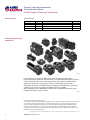
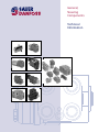
General,
Steering
Components
Technical
Information
General, Steering Components
Technical Information
A Wide Range of Steering Components
Revision History
Table of Revisions
Date
Oct 2002
Dec 2009
Jan 2012
Mar 2012
Page
All
Many
31
33
Changed
First edition
Steering Column deleted
Formula updated
Typo
Rev
AA
BA
BF
BG
A Wide Range of Steering
Components
F300 599
Sauer-Danfoss is the largest producer in the world of steering components for
hydrostatic steering systems on off-road vehicles. Sauer-Danfoss offer steering solutions
both at component and system levels. Our product range makes it possible to cover
applications of all types - ranging from ordinary 2-wheel steering (also known as
Ackermann steering) to articulated steering, complicated 4-wheel steering, automatic
steering (e.g. by sensor) and remote controlled steering via satellite.
We can offer more than 1500 different steering units and 250 different priority valves
categorized in types, variants and sizes.
T301033
© 2012 Sauer-Danfoss. All rights reserved.
Sauer-Danfoss accepts no responsibility for possible errors in catalogs, brochures and other printed material.
Sauer -Danfoss reserves the right to alter its products without prior notice. This also applies to products
already ordered provided that such alterations can be made without affecting agreed specifications. All
trademarks in this material are properties of their respective owners. Sauer-Danfoss, the Sauer-Danfoss
logotype, the Sauer-Danfoss S-icon, PLUS+1™, What really matters is inside® and Know-How in Motion™ are
trademarks of the Sauer-Danfoss Group.
Frontpage: Photos: F 300 616, F300 618, F300 612, F300 620, F300 611, F300 607, F300 630, F300 631, F300 600, Drawing: 150 - 577. ai
2
520L0468 • Rev BG • Mar 2012
General, Steering Components
Technical Information
A Wide Range of Steering Components
A Wide Range of Steering
Components
(continued)
For hydrostatic steering systems Sauer-Danfoss offers:
• Mini steering units with displacements from 32 to 100 cm3/rev [1.95 to 6.10 in3/rev],
flow up to 20 l/min [5.28 US gal/min], steering pressure up to 125 bar [1813 psi].
• Steering units with displacements from 40 to 1200 cm3/rev [2.44 to 73.2 in3/rev], flow
up to 100 l/min [26.4 US gaL/min, steering pressure up to 240 bar [3481 psi].
• Priority valves for rated flows at 40, 80, 120, 160 and 320 l/min [10.6, 21.1, 31.7, 42.3
and 84.5 US gal/min], pressure up to 350 bar [5076 psi].
• Pilot operated flow-amplifiers with amplification factors of 4, 5, 8, 10 or 20 for rated oil
flows of 240 and 400 l/min [63.4 and 105.7 US gal/min], steering pressure up to 210
bar [3045 psi].
• Pilot operated steering valve with steering flow up to 100 l/min [26.4 US gal/min],
steering pressure up to 250 bar [3625 psi] and with integrated priority valve for pump
flow up to 120 l/min [31.7 US gal/min].
For electro hydraulic steering systems Sauer-Danfoss offers:
• Pilot operated steering valves (pilot operated by hydrostatic steering unit or by
electrical signal) with steering flows up to 100 l/min [26.4 US gal/min], steering
pressure up to 250 bar [3625 psi].
• Steering units with integrated electrical operated steering valve with steering flow up
to 50 l/min [13.2 US gal/min], steering pressure up to 210 bar [3045 psi].
• Electrical operated steering valves with steering flow up to 40 l/min
[10.57 US gal/min], steering pressure up to 210 bar [3045 psi].
Characteristic features for steering units:
• Low steering torque: From 0.5 Nm to 3 Nm in normal steering situations
• Low noise level
• Low pressure drop
• Many types available: Open center None reaction, Open center Reaction, Closed
center None reaction, Load Sensing, Load Sensing Reaction
• One or more built-in valve functions: relief valve, shock valves, suction valves, none
return valve in P-line and in LS-line
• Optional port connections (according to ISO, SAE or DIN standards)
Characteristic features for electrohydraulic steering system:
• Electrohydraulic steering valve EHPS: High steering pressure requiring smaller
cylinders and flow
• EHPS: Low pilot pressure and flow giving extremely low noise in the cabin
• EHPS: The possibility of manual steering even on very heavy vehicles
• EHPS can be combined with Sauer-Danfoss PVG 32 proportional valve
• Minimization of side acceleration with articulated steering
• Posibility of GPS-, row sensor-, joy stick- steering and vaiable steering ratio
Conversion Factors
1 N•m
1N
1 bar
1 mm
=
=
=
=
[8.851 lbf•in]
[0.2248 lbf ]
[14.50 psi]
[0.0394 in]
520L0468 • Rev BG • Mar 2012
1 cm3
1l
°F
=
=
=
T301034
[0.061 in3]
[0.264 US gal]
[1.8°C + 32]
T301035
3
General, Steering Components
Technical Information
Contents
Contents
Steering Concepts........................................................................................................................................ 6
Hydrostatic Steering....................................................................................................................................... 6
Electrohydraulic Steering System.............................................................................................................. 8
Steering Components, General.............................................................................................................. 9
Steering Components, Product Overview......................................................................................14
Steering Components, Main Data and Features..........................................................................16
OSPM Mini Steering Units..........................................................................................................................16
OSPB, OSPC, OSPR, OSPD Open Center Steering Units..................................................................16
OSPB Closed Center Steering Units .......................................................................................................18
OSPB,OSPC, OSPF, OSPR, OSPD, OSPQ, OSPL, Load Sensing Steering Units...........................18
OLSA/OLS Priority Valves............................................................................................................................21
OSQ Flow Amplifier......................................................................................................................................22
EHPS Pilot Operated Steering Valves......................................................................................................23
OSPE Steering Valve.....................................................................................................................................25
OVPL and OVR Valve Blocks.......................................................................................................................25
Hydrostatic Steering Systems...............................................................................................................26
Open Center Steering System..................................................................................................................26
Load Sensing Steering Systems...............................................................................................................26
Choice of Steering Concept and Components..............................................................................28
Legislation of Steering Systems...............................................................................................................28
General Information..................................................................................................................................29
Technical Data Common............................................................................................................................29
Manual Steering Pressure...........................................................................................................................29
Demands on steering columns................................................................................................................30
Calculation of Steering Systems..............................................................................................................31
Oil Types............................................................................................................................................................36
Particle Content, Degree of Contamination and Filtering..............................................................37
Installation.......................................................................................................................................................37
Tightening Torques.......................................................................................................................................38
Starting Up andRunning In . .....................................................................................................................38
Maintenance ..................................................................................................................................................38
Examples of Steering Systems..............................................................................................................39
OSPC ON, OSPC OR.......................................................................................................................................39
OSPC, OSPF......................................................................................................................................................40
OSPD LS, OSPQ LS.........................................................................................................................................41
OSPBX LS and OSQA....................................................................................................................................42
EHPS ..................................................................................................................................................................44
OSPE . ................................................................................................................................................................46
Load Sensing Steering System.................................................................................................................47
4
520L0468 • Rev BG • Mar 2012
General, Steering Components
Technical Information
Technical Literature Survey
Survey of Literature
with Technical Data on
Sauer-Danfoss Steering
Components
Detailed data on all Sauer-Danfoss steering components and accessories can be found in
our steering component catalogues, which is divided in to 6 individual sub catalogues:
• General information
Steering components
• Technical data on mini steering units
OSPM
• Technical data on open center, and
closed center steering units
OSPB, OSPC, and OSPD
• Technical data on load sensing steering
units, priority valves and flow amplifiers
OSPB, OSPC, OSPF, OSPD, OSPQ,
OSPL, OSPBX, OSPLX, OVPL, OLS and
OSQ
• Technical data on hydraulic and electrohydraulic pilot operated steering valves,
electrical actuation modules and
appropriate steering units.
EHPS, EHPS w. OLS 320, PVE for
EHPS and OSPCX
• Technical data on combined steering
unit/electro hydraulic steering valves and
steering wheel sensors
OSPE and SASA
The most important data on all Sauer-Danfoss steering components is highlighted in a
general survey brochure.
For technical information on individual variants, please contact the Sauer-Danfoss Sales
Organization.
T301036
520L0468 • Rev BG • Mar 2012
5
General, Steering Components
Technical Information
Steering Concepts
Hydrostatic Steering
Sauer-Danfoss steering components are used in vehicles where the driver has to control
high steering forces, reliably, comfortably and with maximum safety.
Steering Units OSPM/OSPB/OSPC/OSPF/OSPR/OSPD/OSPQ/OSPL
The operation of Sauer-Danfoss steering units OSP- is hydrostatic. That is to say, there is
no mechanical connection between the steering column and the steered wheels.
Instead there are hydraulic pipes and hoses between steering unit and steering
cylinder(s). When the steering wheel is turned, the steering unit meters out an oil volume
proportional to the rate of rotation of the steering wheel. This volume is directed to the
appropriate side of the steering
cylinder, while simultaneously
the displaced oil is directed to
tank.
In open center systems the
steering unit is supplied with
oil from a separate pump with
fixed displacement.
F300 596
Open center hydrostatic steering system
In load sensing (LS)systems one
pump can supply oil to steering
system and to working hydraulics.
A priority valve ensures that
steering always has first priority.
F300 456
Load sensing hydrostatic steering system
6
520L0468 • Rev BG • Mar 2012
General, Steering Components
Technical Information
Steering Concepts
Hydrostatic Steering
Flow-Amplifiers OSQA/OSQB
In large vehicles and ships the steering units can be used with Sauer-Danfoss Flowamplifiers which amplify the oil flow to the steering cylinders. These systems with
steering units and flow-amplifiers also include an inbuilt priority valve which ensures
that the steering takes priority.
When the steering wheel is turned, the oil flow is divided in the flow-amplifier in such
a way as to ensure that the necessary oil flow is led to the steering system.
The rest of the oil flow is available for the working hydraulics.
F300 595
Load sensing hydrostatic steering system with flow amplifier
520L0468 • Rev BG • Mar 2012
7
General, Steering Components
Technical Information
Steering Concepts
Electrohydraulic
Steering System
Electrohydraulic Steering
On loaders, large forklift trucks, dumpers, heavy tractors, combine harvesters, maize
harvesters and other similar machines there is often need for electrically actuated
steering either in the form of a joystick, or fully automatic.
For this purpose Sauer-Danfoss has developed a pilot operated steering valve, EHPS:
Electro Hydraulic Power Steering.
A basic system (type 0) consists of a pilot steering unit as the signal source and an
EHPS valve block which controls oil flow to the steering cylinders proportional to the
pilot flow. The system can be extended to include an electrical actuator so that, as an
alternative, it becomes possible to steer with a joystick (EHPS type 1).
In addition, the valve block can be supplied with built-in micro controller and safety
critical steering software (EHPS type 2). A steering system with EHPS type 2 means no
steering wheel drift and posibility of variable sterring ratio.
F301 273
F300 597
Electrohydraulic steering system
8
520L0468 • Rev BG • Mar 2012
General, Steering Components
Technical Information
Steering Components, General
Steering Units:
OSPM, OSPB, OSPC,
OSPR, OSPF, and OSPL
1 2
The steering unit consists of a rotary valve and a rotary meter.
Via a steering column the steering unit is connected to the steering wheel of the vehicle.
When the steering wheel is turned, oil is directed from the steering system pump via the
rotary valve (spool and sleeve) and rotary meter (gear wheel set) to the cylinder ports L or
R, depending on the direction of turn. The rotary meter meters the oil flow to the steering
cylinder in proportion to the angular rotation of the steering wheel. If the oil flow from
the steering system pump is too small, the steering unit can function as a manual pump assuming the conditions as described in "Manual steering pressure" on page 28.
3
4
5
6
7
8
9
10
11
12
13
1. Check valve
2. Shock valve
3. Relief valve
4. Housing with
anticavitation
valves
5. Spool
6. Neutral position
spring
7. Sleeve
8. Cross pin
9. Cardan shaft
10. Distributor plate
11. Gear wheel
12.Gear rim
13.End cover
150-573.10
Steering Unit with 2
Rotary Meters: OSPD
The basic function of this type is like the main group of Sauer-Danfoss steering units,
except the gearwheel set (rotary meter). OSPD has 2 rotary meters, which are
mechanically connected. A shift valve determines whether only one or both rotary
meters are active. In the case of no pump supply only one rotary meter is active for
emergency steering. In normal steering situations both rotary meters are active.
1
2
1. Housing with
spool/sleeve set
and valves
2. Cardan shafts
3. Housing for shift
valve
3
4
4.Shift valve
5.Distributor plate
6.Gear wheel sets
7.Intermediate plates
8. End cover
5
6
7
6
7
8
150-583.10
520L0468 • Rev BG • Mar 2012
9
General, Steering Components
Technical Information
Steering Components, General
Steering Unit with
Amplifier Valve:
OSPQ
The basic function of this type is like the main group of Sauer-Danfoss steering units,
except the rotary valve and an amplification valve. OSPQ has an amplification valve,
which adds flow to the oil passing through the rotary meter. In the case of no pump
supply (emergency steering) and at steering wheel speed less than about 10 rev/min
only the rotary meter is active. In normal steering situation at steering with higher
steering wheel speeds, oil is also led to the steering cylinder via the built-in amplification
valve.
1. Amplification valve parts
2. Housing with valve parts
3. Spool
4. Neutral position spring
5. Sleeve
6.Gear wheel set with
cardan shaft, distributor
plate and end cover
1
2
3
4
5
6
150-584.10
Priority Valves:
OLSA and OLS
In systems with Sauer-Danfoss priority valves and load sensing steering units, steering
has first priority. When the steering wheel is turned, the oil flow is distributed in the
priority valve in such a way that the oil flow necessary for steering is led to the steering
unit through the CF (controlled flow) connection. The remaining oil flow is available for
the working hydraulics through the EF (excess flow) connection.
The distribution is controlled by the LS signal from the steering unit, so that the oil flow
to the steering unit is always determined by the actual steering rate.
1. Plug
2. Damping orifice
(PP)
3. Spool
4. Housing
5. Spring
6.LS-plug with
LS-orifice
10
520L0468 • Rev BG • Mar 2012
General, Steering Components
Technical Information
Steering Components, General
Flow-Amplifiers:
OSQA and OSQB
The flow-amplifiers OSQA and OSQB contain a directional valve, an amplification valve, a
priority valve, a pilot pressure relief valve, shock and suction valves.
In addition OSQB contains a back pressure valve. The flow-amplifier amplifies the oil flow
from the steering unit cylinder ports L or R by an amplification factor of 4, 5, 8, 10 or 20.
The amplified oil flow is directed from the flow-amplifier ports CL or CR to the steering
cylinder(s). The amplified flow is proportional to the rate of the steering wheel rotation.
If the oil flow from the pump fails, the flow-amplifier cuts off the amplification and
manual steering through the steering unit is possible under the same conditions as
those mentioned in the section: Manual steering pressure, page 28.
The pressure drop through the flow-amplifier at manual steering is about 5 bar [72.5 psi].
2
1
3
2
4
5
1. Housing
2. Shock and suction valves
3. Back pressure valve
4. Directional spool
5. Pilot pressure relief valve
6. Priority valve
7 Amplification valve
6
520L0468 • Rev BG • Mar 2012
7
1
150-586.10
11
General, Steering Components
Technical Information
Steering Components, General
Steering Valve EHPS
The EHPS is a pilot operated directional valve. Oil from a pilot steering unit or an electrical
signal can actuate the steering valve.
Basicly the EHPS valve contains a directional valve, a priority valve, a pilot relief valve, a
pilot pressure control valve, and shock- and suction valves.
An electric actuation module, PVE, can be fitted onto the EHPS valve. In the type 1 system
the controller is operated by an analog signal and the type 2 system the signal is digital
with Canbus interface and it comprises a micro processor with safety critcal steering
software.
The pilot for the directional valve in EHPS can be supplied either by the flow from steering
unit (cylinder port L or R), or by the flow from the electric actuation module PVE/PVED.
5 11
1 11 2
3
8
6
4
1. Electrical actuation module PVE/PVED
2. Housing
3. Directional spool
4. Shock and suction valve
5.Pilot pressure reduction valve
for steering unit
6.Pilot pressure valve for
electrical actuating module
7. Priority valve
8. Cover
9. Emergency steering valve
10.Pilot pressure relief valve
9
12
520L0468 • Rev BG • Mar 2012
2
2
10
7
P301 018
General, Steering Components
Technical Information
Steering Components, General
OSPE Steering Valve
OSPE with an electrical programmable module (PVED-CL) the following steering features
in electro hydraulic steer mode/field mode are possible:
•• GPS-steering
•• Row sensor/ camera steering
•• Joy stick or mini st. wheel steering
•• Variable steering ratio
•• Speed depending steering ratio
This block diagram shows all input devices possible for the PVED-CL actuator/controller.
Detailed description is to be found in seperate literature, PVED-CL User Manual, please
contact Sauer-Danfoss Sales Organization.
The OSPE includes the following main components
Designation of OSPE elements
Item Description
1
Shock valves
2
Suction valves
3
Spool/sleeve set
5
Gear set
Mode select and EH cut
7
off valve
8
EH directional valve
9
PVE control unit
10
LVDT transducer
11
Solenoid valve bridge
Control valve for mode
12
select
Pilot reduction valve,
13
12 bar
14
PP damping orifice
15
Priority valve spool
16
Priority valve spring
17
Dynamic orifice
18
Pilot pressure relief valve
21
PVFC valve/LS resolver
Neutral spring package
22
for spool/sleeve
18
9, 10, 11
8
14, 15, 17
16
7
21
13
12
2
22
1
3
5
P301 216
520L0468 • Rev BG • Mar 2012
13
General, Steering Components
Technical Information
Steering Components, Product Overview
Description
Mini steering unit for smaller vehicles
Steering unit with no valve functions
Steering unit with valve functions
OSPF
OSPD
OSPQ
OSPL
OSPBX
OSPLX
OSPCX
OSPCX
Variants
ON, PB
ON, CN, LS,
ON, OR, LS,
LSd, LSR, LSRd
LSd
ON, LSd, LSRd
LSd, LSRd
LS, LSd
LS
LS
LSd
CN
Priority Valves
OLSA
OLS
LS, LSd
LS, LSd
Priority valve for flanging on steering unit
Priority valve for in line use
Flow-Amplifiers
OSQA
LS
OSQB
LS
OSQB/OLSQ LSd
Flow-amplifier
Flow-amplifier with back pressure valve
Flow-amplifier with priority valve for emergency circuit
Steering Valve
EHPS type 0
LSd
Pilot operated steering valve
Electrohydraulic Power
Steering
EHPS type 1
EHPS type 2
OSPE
LSd
LSd
LSd, LSRMd
Pilot operated steering valve with electrical actuation module
Pilot operated steering valve with programmable electrical actuation module
Combined steering unit/electrohydraulic steering valve
Valve Blocks
OVPL
OVR
-
Valve block for OSPL
Angular block for side ported steering units
Steering Units
Type
OSPM
OSPB
OSPC
Steering unit full drain dynamic load sensing and with valve functions
Steering unit with 2 displacements and with valve functions
Steering unit with flow amplification and with valve functions
Steering unit for larger vehicles
Pilot steering unit for OSQ static
Pilot steering unit for OSQ static
Pilot steering unit for OSQ dynamic
Pilot steering unit for EHPS
Variant
Explanations
ON:Open center Non-reaction LS:
Load Sensing, static
OR: Open center Reaction
LSd: Load Sensing, dynamic
CN: Closed center Non-reaction LSR: Load Sensing Reaction, static
PB: Power Beyond
LSRd: Load Sensing Reaction, dynamic
LSRMd: Load Sensing Reaction RM-technology, dynamic
14
520L0468 • Rev BG • Mar 2012
General, Steering Components
Technical Information
Notes
Notes
520L0468 • Rev BG • Mar 2012
15
General, Steering Components
Technical Information
Steering Components, Main Data and Features
OSPM Mini Steering
Units
For light vehicles such as garden tractors,
municipal vehicles, lawn mowers, small fork
lift trucks, etc., Sauer-Danfoss offers OSPM
hydrostatic steering units.
The OSPM mini-steering unit is available
in two versions:
•• Open center Non-reaction (ON)
•• Power Beyond (PB), where surplus oil can
be led to working hydraulics.
F300 016
Main data of OSPM
•• Displacement: 32 - 100 cm3/rev [1.95 - 6.10 in3/rev]
•• Flow, recommended: 3 - 20 l/min [0.79 - 5.28 US gal/min]
•• Max. steering pressure:125 bar [1812 psi]
•• Max. back pressure (T): 20 bar [290 psi]
Features of OSPM:
•• Small dimensions and low weight
•• Low steering torque 0.5 to 1.5 Nm [4.43 to 13.28 lbf.in]
•• One or more built-in valve functions:
pressure relief, shock in L + R (servo ports Left and Right) and / or non return in P
(Pump connection)
•• End ports with integrated fittings (ORFS): O-ring face seal
•• Possibility of integrated steering column
OSPB, OSPC, OSPR, OSPD
Open Center Steering
Units
For small to large vehicles typically tractors, harvesters, fork lifts, contractors machines
and special vehicles, etc., Sauer Danfoss offers a wide range of hydrostatic steering units.
For open circuit systems, where a seperate fixed displacement pump is supplying the
steering system with oil the following types of Sauer-Danfoss steering units are suitable:
OSPB, OSPC, OSPR and OSPD
OSPB ON
The OSPB Open center steering unit is
avaiable in one version:
•• Open center Non-reaction (ON)
Main data of OSPB ON:
•• Displacement:
50 - 500 cm3/rev [3.05 - 30.5 in3/rev]
•• Flow, recommended:
5 - 70 l/min [1.32 - 18.5 US gal/min]
–– Max. steering pressure: 210 bar[3045 psi]
–– Max. back pressure: 40 bar [580 psi]
16
520L0468 • Rev BG • Mar 2012
F300 619
General, Steering Components
Technical Information
Steering Components, Main Data and Features
OSPC ON/OR
The OSPC Open center steering unit is
available in two versions:
•• Open center Non-reaction (ON)
•• Open center Reaction (OR)
Main data of OSPC ON:
•• Displacement: 40 - 500 cm3/rev [2.44 - 30.51 in3/rev]
•• Flow, recommended: 4 - 70 l/min [1.06 - 18.49 US gal/min]
•• Max. steering pressure: 210 bar [3045 psi]
•• Max. back pressure: 40 bar [580 psi]
F300 618
Main data of OSPC OR:
•• Displacement: 40 - 200 cm3/rev [2.44 - 12.21 in3/rev]
•• Flow, recommended: 4 - 50 l/min [1.06 - 13.21 US gal/min]
•• Max. steering pressure: 210 bar [3045 psi]
Features of OSPB and OSPC Open center steering units:
•• Low steering torque 0.8 to 3.0 Nm [7.08 to 26.6 lbf.in] in normal steering situations
due to low effort springs and wide control range.
•• Low noise due to laminar flow conditions throughout profile-grinded passages.
•• OSPC: one or several built in valve functions: pressure relief, shock in L + R,
suction in L + R and / or non-return in P.
OSPD ON/OR
The OSPD Open center steering unit is
available in two version:
•• Open center Non-reaction (ON) version
•• Open center Reaction (OR) version
Main data of OSPD ON:
•• Displacement : –– From 60 cm3/rev to max 125 cm3/rev
[3.66 to max. 7.63 in3/rev] during manual steering
F300 613
without pump oil supply and with one rotary meter active.
–– From 185 cm3/rev up to 440 cm3/rev [11.3 up to 26.9 in3/rev] at full oil supply and with both rotary meters active.
•• Flow, recommended: 19 - 70 l/min [5.02 - 18.49 US gal/min]
•• Max. steering pressure: 210 bar[3045 psi]
•• Max. back pressure: 40 bar [580 psi]
Main data of OSPD OR
•• Displacement:
–– 60 cm3/rev or 70 cm3/rev [3.66 in3 or 4.27in3/rev] during manual steering
–– From 185 cm3/rev up to 220 cm3/rev [11.28 up to 13.42 in3/rev] at full oil supply
•• Flow recommended: 12 - 50 l/min [3.17 - 13.21 US gal/min]
•• Max. steering pressure: 210 bar [3045 psi]
•• Max. back pressure: 40 bar [580 psi]
Features of OSPD Open center steering units:
•• Features like OSPC Open center steering units plus:
–– Possibility of manual steering of heaviest vehicles, without the need for an
emergency pump.
520L0468 • Rev BG • Mar 2012
17
General, Steering Components
Technical Information
Steering Components, Main Data and Features
OSPB Closed Center
Steering Units
OSPB CN
For constant-pressure systems with variable pump flow Sauer-Danfoss offers the steering
unit types: OSPB CN
The OSPB closed center steering unit is available in one version:
•• Closed center Non-reaction (CN)
Main data of OSPB CN:
•• Displacement: 50 - 400 cm3/rev [3.05 - 24.4 in3/rev]
•• Flow:5 - 50 l/min [1.32 - 13.20 US gal/min]
•• Max. steering pressure:175 bar [2538 psi]
•• Max. back pressure: 40 bar [580 psi]
F300 619
OSPB,OSPC, OSPF, OSPR,
OSPD, OSPQ, OSPL, Load
Sensing Steering Units
For small to large vehicles typically tractors, harvesters, fork lifts, contractors machines
and special vehicles, etc., Sauer Danfoss also offers a wide range of hydrostatic
steering units of the Load Sensing (LS) types: OSPB, OSPC,OSPF, OSPD and OSPQ
LS steering units are for Load Sensing systems, where oil is supplied by a pump via a
priority valve or from a pump with variable displacement.
OSPB LS and
OSPC LS/LSR
The OSPB and OSPC Load Sensing
steering unit is available in three versions:
•• Load Sensing non-reaction (LS) static
•• Load Sensing non-reaction (LS) dynamic
•• Load Sensing Reaction (LSR) dynamic
(only OSPC)
F300 617
Main data of OSPB LS and OSPC LS:
•• Displacement: 40 - 400 cm3/rev [2.44 - 24.4 in3/rev]
•• Flow: 4 - 40 l/min [1.06 - 10.57 US gal/min]
•• Max. steering pressure: up to 210 bar [3045 psi]
•• Max. back pressure: 40 bar [580 psi]
Main data of OSPC LSR:
•• Displacement: 40 - 200 cm3/rev [2.44 - 12.20 in3/rev]
•• Flow: 4 - 20 l/min [1.06 - 5.28 US gal/min]
•• Max. steering pressure: 210 bar[3045 psi]
•• Max. back pressure: 40 bar [580 psi]
Features of OSPB and OSPC Load Sensing steering units:
•• Low steering torque 0.8 to 3.0 Nm [ 7.08 to 26.55 lbf.in] in normal steering situations
•• Low noise
•• OSPC: one or several built in valve functions: pilot pressure relief, shock in L + R, suction in
L + R and/or non-return in P. OSPC LS/LSR Dynamic: non-return valve in LS-connection.
18
520L0468 • Rev BG • Mar 2012
General, Steering Components
Technical Information
Steering Components, Main Data and Features
OSPF LS
The OSPF Load Sensing steering unit is
available in one version:
•• Full drain Load Sensing non-reaction
(LS) dynamic
Main data of OSPF LS:
•• Displacement: 80 - 400 cm3/rev [4.88 - 24.4 in3/rev]
•• Flow: 8 - 40 l/min [2.11 - 10.57 US gal/min]
•• Max. steering pressure:210 bar [3045 psi]
•• Max. back pressure: 40 bar [580 psi]
F300 617
Features of OSPF Load Sensing steering units:
•• Low steering torque 0.5 to 1.8 Nm [4.43 to 15.93 lbf.in]in normal steering situations
•• Low noise and wide control range
•• Higher max. steering speed, limited only by the capacity of the pump and the
pressure setting
•• One or several built in valve functions: pilot pressure relief, shock in L + R,
suction in L + R and / or non-return in P.
OSPD LS/LSR
The OSPD Load Sensing steering unit is
available in two versions:
•• Load Sensing non-reaction (LS) dynamic
•• Load Sensing Reaction (LSR) dynamic
Main data of OSPD LS:
F300 612
•• Displacement : –– From 60 cm3/rev to max 125 cm3/rev [3.66 to max. 7.63 in3/rev] during manual
steering without oil supply and with one rotary meter active.
–– From 185 cm3/rev up to 440 cm3/rev [11.28 up to 26.9 in3/rev] at full oil supply and with both rotary meters active.
•• Flow: 19 - 44 l/min [5.02 - 11.62 US gal/min]
•• Max. steering pressure: 210 bar [3045 psi]
•• Max. back pressure: 40 bar [580 psi]
Features of OSPD Load Sensing steering units:
•• Features like OSPC LS plus :
–– Possibility of manual steering of heaviest vehicles, without the need for an emergency
pump.
Main data of OSPD LSR:
•• Displacement :
–– From 60 cm3/rev or 70 cm3/rev [3.66 or 4.27 in3/rev] during manual steering
–– From 185 cm3/rev to 220 cm3/rev [11.28 to 13.42 in3/rev] at full oil supply
•• Flow: 19 - 22 l/min [5.02 - 5.81 US gal/min]
•• Max. steerring pressure: 210 bar [3045 psi]
•• Max. back pressure: 40 bar [580 psi]
520L0468 • Rev BG • Mar 2012
19
General, Steering Components
Technical Information
Steering Components, Main Data and Features
OSPQ LS/LSR
The OSPQ Load Sensing steering unit is
available in two versions:
•• Load Sensing non-reaction (LS) dynamic
•• Load Sensing Reaction (LSR) dynamic
Main data of OSPQ LS:
F300 615
•• Displacement :
–– From 80 cm3/rev to 160 cm3/rev [4.88 to 9.76 in3/rev] during manual steering with out pump oil supply and in normal steering situations at steering wheel speed less than about 10 rev/min.
–– From 100 cm3/rev to 320 cm3/rev [6.10 to 19.53 in3/rev] at full oil supply and with steering wheel speed above 20 rev/min.
•• Flow: 8 - 32 l/min [2.11 - 8.45 US gal/min]
•• Max. steering pressure: 210 bar [3045 psi]
•• Max. back pressure: 40 bar [580 psi]
Main data of OSPQ LSR:
•• Displacement : –– From 80 cm3/rev to 160 cm3/rev [4.88 to 9.76 in3/rev] during manual steering without oil supply and in normal steering.
–– From 100 cm3/rev to 200 cm3/rev [6.10 to 12.21in3/rev] at full oil supply.
Features of OSPQ Load Sensing steering units:
•• Features like OSPC LS plus
–– Possibility of manual steering of heavier vehicles, without the need for an
emergency pump.
OSPL LS
For larger vehicles typically heavy fork lift
trucks, loaders and dumpers, Sauer-Danfoss
also offers a hydrostatic steering units of
the Load Sensing (LS) type optimized for
high steering flow: OSPL.
The OSPL Load Sensing steering unit is
available in two versions:
•• Load Sensing non-reaction (LS) static
•• Load Sensing non-reaction (LS) dynamic
F300 611
Main data of OSPL LS:
•• Displacement : 520 - 1200 cm3/rev [31.8 - 73.2 in3/rev]
•• Flow:52 - 100 l/min [13.74 - 26.4 US gal/min]
•• Max. steering pressure:210 bar [3045 psi]
•• Max. back pressure: 40 bar [580 psi]
Features of OSPL Load Sensing steering units:
•• Low steering torque 0.8 to 3.0 Nm [7.08 to 26.6 lbf. in] in normal steering situations
•• Low noise
•• Low pressure drop even at high flow
•• Possibility of built in valve function: pilot pressure relief valve. The OVPL valve block
for OSPL contains shock L + R, suction L + R, non-return in pump line and / or back
pressure valve in tank connection.
20
520L0468 • Rev BG • Mar 2012
General, Steering Components
Technical Information
Steering Components, Main Data and Features
OLSA/OLS Priority Valves
For Load Sensing systems, Sauer-Danfoss
offers a wide range of priority valves:
Priority valves for flang mounting to SauerDanfoss LS-Steering units:
OLSA (Except for OSPR, OSPQ and OSPL)
Priority valves for in-line use: OLS
The OLSA and OLS priority valves are
available in two versions:
•• Static and
•• Dynamic
OLSA
F300 625
OLS 40/80
F300 624
Main data of OLSA:
•• Flow, rated: 40 or 80 l/min
[10.57 - 21.1 US gal/min]
•• Max. system pressure: 250 bar [3625 psi]
OLS 120
F300 623
Main data of OLS:
•• Flow, rated: 40, 80, 120, 160 or 320 l/min
[10.57, 21.1, 31.7, 42.3 or 84.5 US gal/min]
•• Max. system pressure: 250 bar [3625 psi]
–– OLS 160: 350 bar [5076 psi] on P and
EF port
OLS 160
Main data of OLSP:
•• Flow, rated: 80 l/min [21.1 US gal/min]
•• Max. system pressure: 250 bar [3625 psi]
OLSP
F300 622
F301 266
Features of OLSA and OLS priority valves:
•• Low noise valves
•• OLS 160 and OLS 320: available with
pilot pressure relief valve
OLS 320
F301 470
520L0468 • Rev BG • Mar 2012
21
General, Steering Components
Technical Information
Steering Components, Main Data and Features
OSQ Flow Amplifier
For very heavy vehicles typically very large
fork lift trucks, loaders, dumpers and special
vehicles weighing one hundred ton or more,
Sauer-Danfoss offers a flow-amplifier to
amplifie the oil from the stering unit: OSQ.
The OSQ is based on the load sensing
steering principle.
The OSQ is available in three versions:
•• OSQA for normal fittings connection
•• OSQB with back pressure valve in tank
connection and for flange type fittings
•• OSQB/OLSQ with priority valve for
emergency steering circuit
OSQB
F300 630
OSQB/OLSQ
Main data of OSQ:
•• Amplification factors : 4, 5, 8,10 or 20
•• Total displacement of steering system:
640 - 4160 cm3/rev [39 - 254 in3/rev]
•• Flow:OSQA: 240 l/min [63.4 US gal/min]
OSQB: 400 l/min [105.7 US gal/min]
•• Max. steering pressure: 210 bar [3045 psi]
F300 646
Features of OSQ flow-amplifier:
•• High steering capacity
•• Low pressure drop even at high flow
•• Possibility of built in valve functions: pilot pressure relief valve, priority valve, shock
and suction valves in L + R. OSQB also has back pressure valve in tank connection.
•• OSQB/OLSQ has flanged on priority valve for emergency steering circuit
Pilot Steering Units:
OSPBX, OSPLX, OSPCX
Load Sensing Steering
Units
The OSQ flow-amplifiers require special
pilot steering units of the type
•• OSPBX LS
•• OSPLX LS or
•• OSPCX LS
which are all load-sensing steering units
whose L- and R- connections are open
to tank in neutral position.
OSPBX LS
The “X LS” steering units are available in three versions:
•• OSPBX LS for OSQA and OSQB
•• OSPLX LS for OSQA and OSQB
•• OSPCX LS with pilot pressure relief valve for OSQB/OLSQ
Main data of the “X LS” steering units:
Displacement OSPBX LS and OSPCX LS 160 - 400 cm3/rev [9.76 - 24.4 in3]
Displacement OSPLX LS 520 - 630 cm3/rev [31.7 - 38.4 in3]
Maximum steering pressure 210 bar [3045 psi]
22
520L0468 • Rev BG • Mar 2012
F300 614
General, Steering Components
Technical Information
Steering Components, Main Data and Features
EHPS Pilot Operated
Steering Valves
For larger vehicles typically big tractors,
heavy fork lift trucks, loaders and dumpers,
Sauer Danfoss also offers a hydraulic and
electro-hydraulic pilot operated steering
valve type EHPS.
EHPS systems are available in three versions.
EHPS Type 0
EHPS Type 0, hydrostatic steering system:
EHPS Type 0 is a purely hydraulic steering system with the EHPS valve acting as a pilot
operated directional valve. A steering unit acts as a pilot unit delivering oil at a low
pressure and low flow. The steering unit needs less displacement as in an ordinary
hydrostatic steering system. The displacement can be optimised for emergency steering.
F300 609
Joystick
OSP
Q
PVE
EHPS valve
Q
Steering
cylinger
150-566.10
EHPS Type 1
EHPS Type 1, hydrostatic and electrohydraulic steering system:
This system consists of an EHPS valve
(type 0) equipped with an electrical
activation unit (PVE). There are 2 possibilities of steering:
either hydraulic with the steering wheel or
electrical using a signal from, for example,
a joystick.
The valve gives highest priority to the
signal from the steering wheel.
F300 610
Joystick
OSP
Q
PVE
EHPS valve
Q
Steering
cylinger
150-566.10
520L0468 • Rev BG • Mar 2012
23
General, Steering Components
Technical Information
Steering Components, Main Data and Features
EHPS Type 2
EHPS Type 2, hydrostatic and electrohydraulic steering system:
This system consists of an EHPS valve equiped
with an electrical activation unit (PVED), steering
wheel sensor and position sensor.
Then it is possible to steer by wire with active
hydraulic back up.
The safety system in the integrated
microcontroller gives steering with an electrical
signal a very high level of safety.
The characteristics are variable steering ratio on the steering wheel, elimination of
steering wheel drift and the possibility of communicating with automatic steering.
F301 545
Steering Wheel Sensor
SASA
Joystick
OSP
Q
PVED CL
EHPS valve
Vehicle Speed
Q
Steering
cylinger
Position Seorn
CAN bus
150-565.11
Main data of EHPS:
•• Flow for steering:
up to 100 l/min [26.4 US gal/min]
•• Max. steering pressure: 250 bar [3625psi]
•• Max. pump flow to priority valve in EHPS: 150 l/min [31.6 US gal/min]
Features of EHPS:
•• High steering pressure requiring smaller steering cylinders.
•• Low pilot pressure up to 30 bar [435 psi] for the pilot steering function giving an
extremely low noise level in the cab.
•• With integrated valve functions: pilot pressure relief, priority, shock and suction in
L + R and pilot pressure control.
•• Possibility of emergency steering (manual) in the event of pump failure.
•• Minimal side acceleration on vehicles with articulated steering.
•• Micro controller with safety critical software means:
–– No steering wheel drift.
–– Possibility of variable steering ratio.
–– Possibility of automatic steering
–– CAN-bus interface.
•• EHPS can be built together with Sauer-Danfoss proportional valves (PVG 32).
Pilot steering Unit OSPCX
CN for EHPS
The EHPS pilot operated steering valve requires a special pilot steering unit, viz:
•• OSPCX CN
that is a closed-center steering unit whose L- and R-connections are open to tank in
neutral position.
Main data of the OSPC CN steering units:
Displacement:
50-200 cm3/rev [3.05 - 12.20 in3]
Maximum pilot steering pressure:
30 bar (435 PSI)
24
520L0468 • Rev BG • Mar 2012
General, Steering Components
Technical Information
Steering Components, Main Data and Features
OSPE Steering Valve
The OSPE Load Sensing Steering Valve is
available in 4 version:
•• Load Sensing non-reaction (LS) dynamic
•• Load Sensing Reaction (LSRM) dynamic
•• “D” Load Sensing non-reaction (D-LS)
dynamic with double gear set
•• “D” Load Sensing Reaction (D-LSRM)
dynamic with double gear set
F500 023
Main data of OSPE
•• Displacement: 100-500 cm3/rev [6.10 - 30.51 in3]
•• Flow, steering wheel steering: 10-50 l/min [2.64-13.21 US gal/min]
•• Flow, EH Steering: 12-40 l/min [3.17-10.57 US gal/min]
•• Max flow to priority valve in OSPE: 90 l/min [23.78 US gal/min]
•• Max steering pressure: 210 bar [3045 psi]
•• Max back pressure: 25 bar [363 psi]
Features of OSPE
•• Integrated EH valve in hydraulic steering unit
•• True “safe-state”: Shut-off valve for EH part
•• Selectable “reaction” - Non-reaction” steering modes
•• Integrated priority valve
OVPL and OVR Valve
Blocks
For the OSPL Load Sensing unit Sauer-Danfoss offers a flange on valve block: OVPL
Main data of OVPL:
•• Flow: 100 l/min [26.4 US gal/min]
•• Max. pressure setting: 270 bar [3916 psi]
on shock valves
Features of OVPL valve block:
•• Double service ports (2x L and 2x R) as option
•• Possibility of built in valve functions:
shock and suction in L + R, non-return in
pump line, back pressure in tank line.
The OVR is designed specially for applications where pipes and/or hoses must run
parallel with the steering column axis of
the steering unit, and where space is
limited.
The OVR contains no valve functions.
F300 629
F300 626
The OVP, OVPL and OVR can only be used in connection with steering units without
spot facing around the port connections on the port surface.
520L0468 • Rev BG • Mar 2012
25
General, Steering Components
Technical Information
Hydrostatic Steering Systems
Open Center
Steering System
In Open center systems a fixed
displacement pump constantly supplies
oil to the steering circuit separately.
Features of open center steering
systems with Sauer-Danfoss open
center steering units:
•• Immediate reaction of the steered
wheels, once the steering wheel
begins to turn.
•• High steering comfort maintained
throughout significant changes of
steering load and pump oil flow.
•• Damping characteristics when
system-conditioned pressure
variations occur.
•• Simple system build-up with stable
steering under all conditions.
Load Sensing
Steering Systems
150-568.10
In Load Sensing steering systems the oil
for the steering system is supplied by a
pump via a priority valve or from a pump
with variable displacement.
For Load Sensing systems Sauer-Danfoss
offers 3 basic types of steering units:
Features of Load Sensing Static
steering systems with Sauer-Danfoss
LS Static steering units:
OSP LS Static
•• First generation of load sensing
•• No flow through the steering unit
when not steering: minimum loss of
energy.
150-569.10
26
520L0468 • Rev BG • Mar 2012
General, Steering Components
Technical Information
Hydrostatic Steering Systems
Load Sensing
Steering Systems
(Continued)
Features of Load Sensing Dynamic
steering systems with Sauer-Danfoss
LS Dynamic steering units:
OSP LS Dynamic
•• Second generation of load sensing
•• Constant flow through the unit when
not steering, recommended level:
•• 0.6 - 0.9 l/min [0.16 - 0.24 US gal/min]
•• Dynamic flow causes quick reaction
time when starting to steer (no hard
spot)
•• Check valve in P-line and in LS-line of
steering unit avoids kick back at the
steering wheel
•• Steering unit always has the same
temperature as the oil in the entire
system, therefore no risk of sticking
spool/sleeve set in housing even
when starting up under very cold
conditions
150-570.10
Features of Load Sensing Dynamic
steering systems with Sauer-Danfoss
OSPF LS steering units:
OSPF LS Dynamic
•• Third generation of load sensing:
full drain load sensing dynamic
•• Constant flow through the unit when
not steering, recommended level:
1 - 1.5 l/min [0.26 - 0.40 US gal/min]
•• Dynamic flow eliminates hard point
when starting steering
•• No kick back in steer wheel because of
check valve in P- and no connection
P-line to LS-line
•• Steering unit always has the same
temperature as the oil.
•• OSPF is extremely good in controlling
negative steering forces
•• Higher max. steering speed, limited
only by the capacity of the pump and
the pressure setting
150-571.10
520L0468 • Rev BG • Mar 2012
27
General, Steering Components
Technical Information
Choice of Steering Concept and Components
Choice of Steering
Concept and
Components
The choice of steering concept is determined mainly by vehicle design, performance
requirements and required operating functions.
When a hydrostatic system is chosen, the next step involves deciding whether the
hydraulic steering system is to be:
•• Open Center steering system
•• Power Beyond steering system
•• Closed Center non-Load-Sensing steering system
•• Load Sensing steering system
The choice will also depend on system cost requirements, hydraulic system energy
consumption and system complexity.
When a Load Sensing system has been chosen, there are three further possibilities:
•• Load Sensing Static steering system
•• Load Sensing Dynamic Steering system
•• Load Sensing Dynamic steering system based on Sauer-Danfoss OSPF steering units
The choice here will depend on performance requirements and running-in complexity:
•• Load Sensing Static steering systems are the simplest Loading Sensing types as
regards the initial setting up of the priority valve spring/orifices combination.
•• Load Sensing Dynamic steering systems give, in most cases, better steering
performance than Static steering systems. See page 26.
•• Load Sensing Dynamic steering systems with OSPF steering units give by far the best
steering characteristics. See page 26. Such a system can require highly precise setting
up of the priority valve spring/orifices combination and it is essential to ensure high
“dynamic” flow from the priority valve, min. 1 litre/min [0.26 US gal/min].
When specifying a steering system, there are two steering unit options, viz. “Reaction”
and “Non-reaction”:
•• With reaction steering units, any external forces that act on the steered wheels result
in a corresponding movement of the steering wheel, when the driver is not steering
the vehicle
•• With non-reaction steering units there is no such corresponding movement of the
steering wheel, when the driver is not steering the vehicle
For vehicles with rear-wheel steering and articulated steering, or for vehicles that
require a steering unit displacement >250 cm3/rev [15.25 in3/rev], Sauer-Danfoss always
recommends non-reaction steering units.
Size calculations on steering cylinders, steering units and pumps for steering systems are
given in “General information” in the next section.
If a suitable compromise cannot be achieved between minimum necessary
displacement determined by maximum desired number of steering wheel revolutions
from lock to lock, and maximum permissible displacement for building up the steering
pressure in emergency situations with pump failure, it is possible to choose a steering
unit with variable displacement: type OSPD or OSPQ.
Legislation of
Steering Systems
Please pay attention to country specific legislation for hydraulic/electro-hydraulic
steering systems in public traffic. The most wellknown of these in Europe are the German
TÜV regulation § 38stVZo and the ISO 5010 standard.
28
520L0468 • Rev BG • Mar 2012
General, Steering Components
Technical Information
General Information
Technical Data Common
min.
max.
Permissible temperature assuming
Surface treatment
non-activated steering unit
min.
Oil temperature
max.
min.
Recommended oil temperature
max.
min.
Oil viscosity
max.
min.
Recommended viscosity
max.
ON/OR
Max. degree of
Filtration
contamination ISO 4406
LS/CN/PB
Temperature-difference between steering unit
max.
and other hydraulics
Normal steering
Steering torque, OSPM
Manual steering 1)
Momentary load
Normal steering, OSPF
Normal steering, OSPL
Steering torque, other OSP Normal steering other OSP
Manual steering 1)
Momentary load
Ambient temperature
–30°C
+60°C
[–22°F]
[140°F]
120°C [248°F] for 20 minutes
-30°C
[-22°F]
90°C
[194°F]
30°C
[86°F]
60°C
[140°F]
[59 SUS]
10 mm2/s
[4629 SUS]
1000 mm2/s
[66 SUS]
12 mm2/s
[370 SUS]
80 mm2/s
22 / 20 / 17
21 / 19 / 16
∆10°C
[∆18°F]
0.5 - 1.5 Nm
Max. 80 Nm
Max. 160 Nm
0.5 - 1.8 Nm
1.5 - 4.0 Nm
0.8 - 3.0 Nm
Max. 120 Nm
Max. 240 Nm
[4.43 -13.3 lbf·in]
[708 lbf·in]
[1416 lbf·in]
[4.43-15.93 lbf·in]
[13.3 - 35.4 lbf·in]
[7.08 - 26.55 lbf·in]
[1062 lbf·in]
[2124 lbf·in]
1) Steering units must not be used for continuous manual steering, max.1% of life cycle
Manual Steering Pressure
Under normal operating where the steering pump supplies an adequate oil flow at the
required pressure, the maximum torque on the steering wheel will not exceed 5 Nm
[44.2 lbf·in]. If the oil flow from the steering system pump fails or is too small, the
steering unit functions automatically as a manual steering pump.
Manual steering can only be used for a limited control of the vehicle if a sudden drop of
pump pressure or flow occurs.
The table below shows the nominal manual steering pressure (Pm) for all sizes of SauerDanfoss steering units type OSPM at a steering wheel torque of 80 Nm [708 lbf·in].
The values apply only if the suction conditions on the steering unit T port are adequate.
OSPM
Pm
32
50
bar 125
80
[psi] [1813] [1160]
63
65
[945]
80
50
[725]
100
40
[580]
The table below shows the nominal manual steering pressure (Pm) for all types of SauerDanfoss steering units except OSPM at a steering wheel torque of 120 Nm [1062 lbf.in] a
value which is considered to be the maximum torque an average size operator can exert.
The values apply only if the suction conditions on the steering unit T port are adequate.
OSP
Pm
50
60
70
80
100 125 160 200 315 400 500 630 800 1000
bar 120
100
85
75
60
50
40
30
20
15
12
10
8
6
[psi] [1740] [1450] [1235] [1090] [870] [725] [580] [435] [290] [217] [174] [145] [116] [87]
520L0468 • Rev BG • Mar 2012
29
General, Steering Components
Technical Information
Steering Components, Main Data and Features
Demands on steering
columns
To ensure proper steering performance, the following demands must be fulfilled:
•• the steering column must not generate any axial or radial forces on the input shaft of
the steering unit
•• the steering column must only be provided with one bearing (in the top)
•• the welded journal must be coaxial with the spigor hole of the column
Below are stated dimensions for the steering column spline shaft and foot plate to be
fulfilled.
B
Data’s for steering columns for OSPB, OSPC, OSPD, OSPE, OSPF, OSPL and OSPQ steering
units:
0.4
A
0.4
Min 3.0 [0.12]
Involute spline data for steering column
Involute spline data acc. to ANSI B92.1
Teeth
12
Pitch angle
30°
Diametral pitch/stub pitch
16/32
Pitch Diameter
∅19.05 [0.75]
∅20.3±0.1
Outer diameter
[0.80±0.01]
∅16.5 +0.5
Smallest diameter
[0.65 +0.02]
∅23.47 -0.1
Min. diameter over two pins
[0.92 - 0.01]
∅3.048±0.001
Pin diameter
[0.12±0.001]
∅44.5
[∅1.75 +0.1
-0 ]
+0.1
-0
A
B
+0.02
S=T*+6.5 +0.6
-0.9 [0.26 -0.04]
min.15 full spline
P301 251
*T=thickness of console plate.
When column is mounted directly on steering unit,
S=6.5 mm [0.26 in]
A
∅35±0.4
[∅1.38±0.2]
Max 4.0 [0.16]
B
S=13±1-T*
[S=0.51±0.04-T*]
min.15 full spline
1
.00 1]
±0 .00
∅3 12±0
.
0
[∅
[0
+
-0 0
.1
]
2.5
.10 -0+.10
*T=thickness of console plate.
When column is mounted directly on steering unit,
S=13 mm [0.51 in]
0.4 A
Involute spline data for steering column
Involute spline data acc. to DIN5482 A17x14
Teeth
9
∅20 +0.11
-0
Outer diameter
[0.79 +0.04
-0 ]
∅14 +0.11
-0
Smallest diameter
[0.55 +0.04
-0 ]
Min. diameter between
∅11.07 ±0.05
two pins
[0.43 ±0.01]
∅3 ±0.001
Pin diameter
[0.12 ±0.001]
+0
Pin flat grinded
2.5 -0.1
+0]
[0.10 -0.1
against spline bottom
0.4 B
Data’s for steering columns for OSPM steering units:
P301 252
30
520L0468 • Rev BG • Mar 2012
General, Steering Components
Technical Information
General Information
Manual Steering Pressure
(Continue)
In the German TÜV directives, §38stVZo specifies the maximum permissible steeringwheel rim force in an emergency steering situation (Please consult the directives for the
ruling values).
If, for example, the permissible steering wheel rim force is Fe = 350N [78.7 lbf ] and the
steering wheel diameter SWd is = 0.381 m [15”], the steering torque Tsw will be =
Tsw = Fe •
SWd
0.381
= 350 •
= 66.7 Nm [590 lbf·in]
2
2
Accordingly, the obtainable maximum steering pressure will be lower than stated in the
table on page 28.
With, for example, an OSPC 80, the maximum steering pressure Pmr, will be =
Pmr = Pm table x Tsw/Ttable = 75 x 66/120 = 41 bar [598 psi].
Calculation of
Steering Systems
Ackermann Steering
Symbols:
ML (Nm) [lbf.in]:steering torque
F (N) [lbf ]:
steering force
GS (N) [lbf ]:
force on shaft
(weight)
e (mm) [in]:
king pin off-set
B (mm) [in]:
tyre breadth
µS: friction coefficient
S (cm) [in]:
piston stroke): r (m) [ft]:minimum effective
radius arm for
steering cylinders
The force on the shaft is 80.000 N (8.000kg)
[17.984 lbf ] King pin off-set is 100 mm.
[3.94 in]. Tyre breadth is 200 mm [7.87 in]
Friction coefficient between road and
tyres is 0.7. Minimum effective radius
arm for steering cylinders is 0.1 m [3.94
in].
According to Taborek's formula the total
steering torque becomes
1
ML = 0.05 • Gs •
e
1+
B
B
200
µS
0.7
r
S
GS
e
B
1 200 0.7
ML = 0.05 • 80.000 •
•
•
Nm
100
1+ 200 200 0.7
ML = 2667 Nm [23606 lbf.in]
Cylinder piston rods must then produce
a steering force of:
ML
150-268.10
520L0468 • Rev BG • Mar 2012
F=
ML 2667
=
N = 26.670 N [5995 lbf ]
r
0.1
31
General, Steering Components
Technical Information
General Information
Calculation of
Steering Systems
Cylinder
Symbols:
F (N) [lbf ]: steering force
P (bar) [psi]: steering pressure
D (cm) [in]: internal diameter of cylinder
d (cm) [in]: piston rod diameter
S (cm) [in]: piston stroke
V (cm3) [in3]:stroke volume
A: Differential cylinder
When max. steering pressure P is led
to the largest area, the steering force
becomes:
π
F
= P •4 • D2 • 10
At steering to the largest area, the stroke
volume becomes:
A
π
V
=4 • D2 • S
B
With max. steering pressure P acting
on the smallest area, the steering force
becomes:
C
π
F
= P •4 • (D2 − d2) • 10
150-243.10
When using only one differential
cylinder, the number of steering wheel
revolutions from lock to lock will be
different for each direction of rotation.
Use a piston seal in the cylinder to avoid
leakage from one side of the piston to
the other.
At steering to the smallest area, the
stroke volume becomes:
π
V
= 4 • (D2 − d2) • S
B: Balanced cylinder:
π
F
= P • 4 • (D2 − d2) • 10
π
V
=4 • (D2 - d2) • S
C: Cross-connected cylinders:
π
F
= P •4 • (2D2 − d2) • 10
π
V
=4 • (2D2 − d2) • S
32
520L0468 • Rev BG • Mar 2012
General, Steering Components
Technical Information
General Information
Calculation Example
of Steering Cylinder
Cross-connected cylinders are used. The steering force is 30.500 N [6857 lbf ]
The steering pressure is 90 bar [1305 psi]. Piston stroke is 20 cm [7.90 in].
The relation between the piston rod diameter and internal diameter of the cylinder is
d
1
=
for the cylinder chosen.
D
2
π
Inserted
in the formula for steering force 30.500 • 10 = 90 • 4 (2 (2d)2 − d2) • 10
the result is
d = 2.5 cm [1 in] and D = 2 • d = 5,0 cm [2 in].
π Stroke
volume: V = 4 • (2 • 5.02 - 2.52) • 20 = 687 cm3 [41.9 in3]
A theoretical calculation of steering cylinders and steering pressure may result in
inadequate steering forces in many dynamic steering situations in practise.
An empirical rule verifies that adding an approx. 50 bar [725 psi] pressure to the
theoretically required pressure usually always ensures a satisfactory steering
performance.
Based on this empirical rule, the required size of cylinder can be calculated on basis of a
steering pressure that is 50 bar [725 psi] lower than the available system pressure.
Therefore, in the example illustrated above, the steering system must be able to work
with a pump pressure of
90 bar [1305 psi]+ 50 bar [725 psi] = 140 bar [2030 psi]
Calculation Example
of Steering Unit
Symbols:
V cm3 [in3]: stroke volume Vv cm3/rev [in3/rev]: steering unit displacement
i (rev): required number of steering wheel revolutions from lock to lock
V
The required steering unit displacement is calculated from Vv =
i
With a stroke volume of 687 cm3 [41.9 in3] and a required number of steering wheel
revolutions from lock to lock of 3 to 4, the steering unit displacement will be between
172 and 229 cm3/rev. [10.56 and 13.97 in3/rev]. A steering unit with a displacement of
200 cm3/rev [12.20 in3/rev] will give 3.4 steering wheel revolutions.
Calculation Example
of Pump
Symbols:
Vv (cm3/rev) [in3/rev]: steering unit displacement
n (min-1) [rev/min]: required steering wheel speed
Q (l/min) [US gal/min]: oil flow
The oil flow is calculated from
Q = Vv • n • 10-3.
With a displacement of 200 cm3/rev [12.20 in3/rev] and a required steering speed of
100 min-1 [rev/min], the oil flow will be
Q = 200 • 100 • 10-3 = 20 l/min. [5.28 US gal/min]
Steering Wheel
Revolutions and
Steering Speed
Recommended:
Number of steering wheel revolutions from lock to lock: 3 to 5.
Steering wheel speed: 100 to 150 min-1/min [rev/min]
Steering wheel speed with engine at idle: min. 60 min-1/min. [rev/min]
520L0468 • Rev BG • Mar 2012
33
General, Steering Components
Technical Information
General Information
Calculation of
LS Steering System with
Working Hydraulics
Symbols:
Q (l/min) [US gal/min]: required oil flow for the steering system
QA (l/min) [US gal/min]: required oil flow for the remainder of the hydraulic system
Qp (l/min) [US gal/min]: required pump flow
The priority valve ensures priority to the steering system under any situations. In some
cases the steering system can take all the oil flow from the pump.
When it is designed that the steering system and the working hydraulics do not require
oil simultaneously, the necessary oil flow from the pump QP will equal the higher of the
two oil flows (QA or Q).
When working hydraulics and steering system must have oil at the same time, the
necessary oil flow from the pump QP will equal the sum of the two oil flows (QA + Q).
The necessary oil flow to the steering unit is 20 l/min[5.28 US gal/min]. Required for the
working hydraulics 40 l/min [10.56 US gal/min].
If it is acceptable that the working hydraulics drop in speed during steering then
the necessary oil flow from the pump will be: QP = QA = 40 l/min [10.56 US gal/min].
Calculation of
Steering System with
Flow-Amplifier
OSQA/OSQB
Symbols
V (cm3) [in3]: stroke volume
i (min-1) [rev]: required number of steering wheel revolutions from lock to lock
Vv (cm3/rev) [in3/rev]: steering unit displacement
f: amplification factor of Flow-amplifier
Steering unit displacement and amplification factor of the flow-amplifier are calculated
from:
Vv • f =
i
V
Calculation of
Steering System for
Articulated Vehicle
Should you wish to size a steering system for an articulated vehicle, Sauer-Danfoss will
carry out computer calculations for you.
Please take a copy of the questionnaire overleaf, complete it, and send it to the SauerDanfoss Sales organization.
34
520L0468 • Rev BG • Mar 2012
General, Steering Components
Technical Information
General Information
Calculation of
Steering Systems
Manufacturer:
Vehicle:
Units used: fill in with X:
Articulated Vehicle
Weight of fully loaded vehicle: G max.=
Max. speed of vehicle:
Required number of steering wheel revolutions: i =
Steering system pump:
Type:
Max. steering pressure:
Displacement:
Minimum speed:
Maximum speed:
Loader
Bucket width: W=
Other machines
Number of front axles:
Number of rear axles:
mm
[in]
A2 =
mm
[in]
B1 =
mm
[in]
B2 =
mm
[in]
D=
mm
[in]
d=
mm
[in]
± α max. =
mm
[in]
E=
mm
[in]
2 cylinders E = 1
1 cylinder, left E = 2
A2
R
B2
L
A2
A1
B1
R
B2
L
[psi]
[in3]
[rev/min]
[rev/min]
[in]
w
A1
B1
R
bar
cm3
min-1
min-1
mm
1 cylinder, right E = 3
w
A1
US q
[lbf ]
[mph]
[rev]
Notes:
w
A1
metric q
kg
km/h
min-1
B1
A1 =
Date:
Project:
B2
Complete Form
Completed by:
Type:
L
A2
A2
150-317.10
520L0468 • Rev BG • Mar 2012
35
General, Steering Components
Technical Information
General Information
Calculation of
Steering Systems
Pump for FlowAmplifiers OSQA/OSQB
Symbols:
Q (l/min) [US gal/min]: QA (l/min) [US gal/min]: Qp (l/min) [US gal/min]: Vv (cm3) [in3]: f:
n (min-1) [rev/min]: oil flow required for steering components
oil flow required for working hydraulics
oil flow required from pump
steering unit displacement
amplification factor of flow-amplifier
required steering speed
The integral priority valve in the flow-amplifier ensures priority to the steering system.
When it is designed that the steering system and the working hydraulics do not operate
simultaneously, the oil flow required from the pump Qp will equal the higher of the two
oil flows (QA or Q).
Q = VV • f • n • 10-3
When working hydraulics and steering system must have oil at the same time, the oil
flow required from the pump QP will equal the total of the two oil flows (QA + Q).
Oil Types
Mineral Oils,
Non-Flammable or
Biodegradable Hydraulic
Fluids, Sealing Materials,
and Oil Temperature
Mineral oils
When using mineral based hydraulic oil, we recommend the addition of a sufficient
quantity of antiwear additive of a type that is active under boundary lubrication
conditions at low temperatures.
Mineral oils are normally suitable if they belong to one of the three following groups:
•• HM oil, possibly HV (ISO 6743/4, CETOP RP 91H) or H-LP oil (DIN 51524)
•• Automatic Transmission Fluids (ATF A)
•• SE- and CD motor oil (American Petroleum Institute (API))
The large content of additives in motor oils may produce sediment that can block valves
and filters. If there is doubt about the suitability of an oil, please contact Sauer-Danfoss
Sales Organisation.
Non-flammable or biodegradable hydraulic fluids
To an increasing extent Sauer-Danfoss steering components are being used in systems
with non-flammable hydraulic fluids.
These fluids normally belong to one of the following groups according to ISO 12922:
Oil in water emulsion:
HFA
Water in oil emulsion:
HFB
Water/polymer solution: HFC
Waterfree synthetic fluids: HFD-U
Please contact the sales organization for Sauer-Danfoss Sales Organisation regarding the
use of non-flammable or biodegradable fluids.
Sealing materials
The seals in steering components are of nitrile rubber NBR (Buna N) and teflon PTFE.
If synthetic fluid is to be used in the steering system, please contact the Sauer-Danfoss
Sales Organization regarding sealing material.
Oil temperature
Oil life will be drastically reduced because of oxidizing if the operating temperature
exceeds 60 °C [140°F] for long periods.
A rule of thumb is that oil life is halved for each 8 °C [46.4°F] in excess of 80 °C [176°F] .
Impurities in the oil, e.g. particles or water, will further reduce its life.
36
520L0468 • Rev BG • Mar 2012
General, Steering Components
Technical Information
General Information
Particle Content,
Degree of Contamination
and Filtering
Particle content, degree of contamination
The oil must be filtered to prevent the particle content from exceeding an acceptable
level, corresponding to an acceptable degree of contamination. The maximum ISO
degree of contamination (see ISO 4406 or CETOP RP 70) is
•• for load sensing, closed center steering components and power beyond steering
units: 21/19/16
•• for open center steering components: 22/20/17
Filtering
How fine the filtering must be and where the filters are to be placed is always a
compromise.
In systems with a good air filter and effective dust sealing, and which operate in clean
surroundings, the degree of contamination can normally be kept within the limits laid
down by using a return filter of 25 µm nominal (40-50 µm absolute) or finer.
Conversely, systems operating with a poor air filter and inadequate dust sealing - in
dusty surroundings - will often require more than one filter of 10 µm absolute. The filters
can be pressure or return filters.
Installation
••
••
••
••
••
••
••
••
••
••
••
••
••
••
••
Never paint steering unit on steering column surface
All hydraulic components should be placed so that they are easily accessible.
All hydraulic components should be installed outside the cabin of the vehicle.
There should be a manometer connection in the pump line.
Install the cylinders with the ports facing upwards so that air pockets are avoided.
Mounting surfaces should be flat in order to ensure effective contact.
Hydraulic pilot lines must be fitted in such a way that air pockets are avoided.
install the hydraulic components as stated in their individual installation instructions.
Installation instructions are enclosed or can be ordered from Sauer-Danfoss Sales
Organisation.
The hydraulic components must not be forced or twisted into alignment by the fixing
screws.
Packing yarn, teflon, and other unsuitable sealing material must not be used on port
adaptors. Use bonded seals, O-rings, steel washers, and similar materials.
Do not remove the plastic plugs until pipes and hoses are to be fitted.
Never tighten the screwed connections with a torque higher than the max. tightening
torques stated in the instructions.
The oil must have a contamination level better than the ISO 4406 code stated in the
technical data page 28.
Always refill the system through a filter.
520L0468 • Rev BG • Mar 2012
37
General, Steering Components
Technical Information
General Information
Tightening Torques
Connections
G 1⁄4
G 3⁄8
G 1⁄2
G 3⁄4
7⁄16-20 UNF
3⁄4-16 UNF
7⁄8-14 UNF
1 1⁄16-12 UN
M12 • 1.5
M18 • 1.5
M22 • 1.5
9/16 - 18 UNF, ORFS
11/16 - 16 UN, ORFS
With cutting edge
35 [309]
70 [619]
100 [885]
180 [1593]
30 [265]
80 [708]
100 [885]
-
Max. tightening torque Nm [lbf.in]
With copper washer With alum. washer
35 [309]
35 [309]
45 [398]
50 [442]
55 [486]
80 [708]
90 [796]
130 [1150]
20 [177]
30 [265]
55 [486]
70 [619]
65 [575]
80 [708]
-
O-ring
20 [177]
60 [531]
90 [796]
120 [1062]
25 [221]
50 [442]
60 [531]
25 [221]
27 [239]
If in doubt about the choice of connection and sealing principle, please contact the Sauer-Danfoss Sales
Organisation
Starting Up and
Running In
••
••
••
••
••
••
••
••
••
••
Maintenance
38
Start the prime mover and where possible allow it to run at the lowest speed.
Check the direction of pump shaft rotation.
Any bleed screws must be left open until oil emerges without foam.
In load sensing systems ensure that all signal lines are full of oil.
Turn the steering wheel left and right until the steering components are completely
bled.
Signs of air in the hydraulic system
–– foam in the tank
–– jerky operation of actuator motor or cylinder
–– noise
Refill again, if necessary.
The system should not be loaded until completely bled.
The hydraulic system is checked for tightness and satisfactory function.
Change the oil filter, if necessary.
••
•• Careful maintenance is essential to the reliability and life of the hydraulic system.
•• Oil, oil filters, and air filters must be changed in accordance with the supplier’s
instructions.
•• The condition of the oil must be checked at suitable intervals.
•• System tightness and oil level must be checked frequently.
520L0468 • Rev BG • Mar 2012
General, Steering Components
Technical Information
Examples of Steering Systems
Examples of Steering
Systems
OSPC ON,
OSPC OR
L
R
L
OSPC ON
P
T
OSPC ON
steering units contain one or more of the
following possible valve functions:
•• - pressure relief valve
•• - shock valves
•• - suction valves
•• - check valve
520L0468 • Rev BG • Mar 2012
OSPC OR
P
150-367.10
R
T
150-429.10
OSPC OR
steering units contain one or more of the
following possible valve functions:
•• - pressure relief valve
•• - suction valves
•• - check valve
•• - shock valves if needed
39
General, Steering Components
Technical Information
Examples of Steering Systems
Examples of Steering
Systems
OSPC, OSPF
OSPC LS + OLSA
Steering unit with flange mounted
priority valve OLSA and OTPB steering
column with sensor.
OSPF + OLS
Load sensing steering system with
variable displacement pump.
R
L
OSPF LS
OTPB
with sensor
OSPC LS
LS
P
L
P
T
LS
T
R
OLSA
P
T
EF PVG 32
CF
EF
LS
OLS
PVRES
P
152B77.10
150-394.10
When the driver turns the steering wheel,
the steering wheel sensor sends a signal
to the relay box activating the electric
motor that drives the hydraulic system
pump. The system must also include a
signal source in the working hydraulics.
A PVRES control lever for example.
The system is therefore energy-optimised,
so that the hydraulic pump runs only
when the hydraulic functions are active.
40
520L0468 • Rev BG • Mar 2012
The pump and the working hydraulics
circuit must be protected by a separate
pressure relief valve.
General, Steering Components
Technical Information
Examples of Steering Systems
Examples of Steering
Systems
OSPD LS
Steering unit with two rotary meters
OSPQ LS
Steering unit with amplification valve
OSPD LS,
OSPQ LS
L
L
R
R
OSPD LS
T
P
CF
OSPQ LS
P
LS
EF
T
CF
LS
OLS
LS
EF
LS
OLS
P
P
150-475.10
150-574.10
With OSPD or OSPQ even heavy vehicles can in many cases fulfil legislations and be
steered without the emergency steering pump. An OSPD makes it possible to select a
ratio between normal steering displacement and emergency steering displacement up
to a factor of 5.
An OSPQ allows the selection of an amplification factor of up to 2.
The pump and the working hydraulics circuit must be protected by a separate pressure
relief valve.
520L0468 • Rev BG • Mar 2012
41
General, Steering Components
Technical Information
Examples of Steering Systems
OSPBX LS and OSQA
The pilot pressure relief valve in OSQA only protects the steering circuit. The pump and
the working hydraulics circuit must be protected by a separate pressure relief valve.
CL
CR
P
L
OSQA
R
L
R
P
T
LS
OSPBX LS
T
LS
EF
PP
HP
HT
150F57.10
2 x OSPBX LS and OSQB
The steering components are connected by three shuttle valves. The pilot pressure relief
valve in OSQB only protects the steering circuit.
The pump and the working hydraulics circuit must be protected by a separate pressure
relief valve.
Steering systems with flow-amplifiers make it possible to connect working hydraulics to
the EF connection. The built-in priority valve ensures first priority to the steering circuit.
When the steering wheel is turned, the priority valve ensures that the necessary oil flow
is led to the steering circuit. The rest is available for the working hydraulics.
CL
CR
P
L
OSQB
R
L
OSPBX LS
P
R
T
L
R
P
T
OSPBX LS
T
LS
EF
PP
HP
HT
150F58.10
42
520L0468 • Rev BG • Mar 2012
General, Steering Components
Technical Information
Examples of Steering Systems
OSPBX LS and OSQA
Shown with Electrically
Driven Pump for
Emergency Steering.
Amplification During
Emergency Steering
The pump for emergency steering is operated when the pressure in the HP line is below
the stand-by level. The pump for emergency steering supplies the HP line with oil.
So amplification is maintained during emergency steering. The pilot pressure relief valve
in OSQA only protects the steering circuit.
The pumps and the working hydraulics circuit must be protected by separate pressure
relief valves.
CL
CR
P
L
L
P
OSQA
R
R
OSPBX LS
T
T
LS
LS
EF
PP
HP
HT
150F60.10
OSPBCX LS, and OSQB/
OLSQ with Integrated
Priority Valve for
Emergency Circuit
When under normal steering conditions the stand-by pressure in the main circuit
(minimum 7 bar [102 psi]priority valve spring in OSQ) overrules the spring pressure
in OLSQ (4 bar [ 58 psi] spring), OLSQ’s priority valve will pass oil from the emergency
steering pump across OLSQ’s P-connection to the flow amplifier’s HT tank connection.
If the oil supply from the main pump (HP) should fail, the stand-by pressure of OSQ’s
priority valve in the main pump circuit disappears and relocates the spool in OLSQ to
enable the oil from the emergency steering pump to enter the pump circuit (P) in the OSQ.
The pilot pressure relief valve in OSPCX LS only protects the steering circuit. The pumps
and the working hydraulics circuit must be protected by separate pressure relief valves.
OSQB
OSPCX LS
CL
CR
P
L
R
L
R
P
T
LS
T
EF
LS
min. 7 bar
120 psi
HP
4 bar
58 psi
HT
PDR
OLSQ
P
150F72.11
520L0468 • Rev BG • Mar 2012
43
General, Steering Components
Technical Information
Examples of Steering Systems
EHPS
Type 1 Steering Valve
with PVG 32, OSPCX Pilot
Steering Unit and PVRES
Joystick
The vehicle can be steered with either the PVRES joystick or with the OSPCX pilot
steering unit. The signal from the steering unit has priority on simultaneous activation of
steering wheel and joystick.
OTPB
with sensor
OSPC LS
L
P
T
LS
R
OLSA
P
T
EF PVG 32
PVRES
152B77.10
44
520L0468 • Rev BG • Mar 2012
General, Steering Components
Technical Information
Examples of Steering Systems
EHPS
Type 2 Steering Valve
with Control Module
PVED, OSPCX Pilot
Steering Unit and
Joystick
The vehicle can be steered either:
•• automatically with a signal from an external signal source, e.g. range sensor or a GPS
signal, or
•• manually with a joystick, or with an OSPCX pilot steering unit.
The signal from the steering unit has priority:
When the steering wheel is activated, the signal from the automatic steering valve
discontinues and with simultaneous activation of steering wheel and joystick, the
turning direction of the steered road wheels will correspond to the direction of rotation
of the steering wheel.
The signal from the steering wheel sensor gives:
•• variable steering wheel ratio
•• Zero-slip function: the steering wheel position corresponds to the position of the
steering cylinder.
•• The pump and the working hydraulics circuit must be protected by a separate
pressure relief valve.
CL
CR
EHPS
type 2
L
PVRES
R
Signal
generator
Ps
EF
P
T
T
L
P
R
OSPCX CN
Ts
150-576.11
520L0468 • Rev BG • Mar 2012
45
General, Steering Components
Technical Information
Examples of Steering Systems
OSPE
in System with Variable
Pump and GPS Steering
OSPE in a system with variable pump and GPS steering
The pump must have a built in pilot pressure relief valve to protect the OSPE, the priority
valve part, the working hydraulics and the AUX function. AUX can be a brake system,
which must have limited oil consumption to ensure steering capability in any case.
Alternative pressure protection must be present in working and in AUX-hydraulic.
GPS
OSP
L
Display
R
Watchdog
controller
SASA
Rr
Lr
LS
P
EH
PVE
Electronics
PE
TE
LS
P
EF
AUX
520L0468 • Rev BG • Mar 2012
L
R
P301 178
Prime
mover
46
T
Working
Hydraulic
CC
General, Steering Components
Technical Information
Examples of Steering Systems
Load Sensing Steering
System
and Load
Sensing Working
Hydraulics with Common
Oil Supply From A Fixed
Displacement Pump
The pump oil flow is fed in from a priority valve OLS 120 or OLS 160, which ensures
priority to steering.
The built-in pilot pressure relief valve in OSPC LS protects the steering circuit.
The built-in pilot pressure relief valve in Sauer-Danfoss proportional valve PVG 32
protects the working hydraulics circuit.
The first working hydraulics section is shown with a Sauer-Danfoss hydraulic motor .
Shock and suction valves are built into the proportional valve.
The second working hydraulics section is shown with a Sauer-Danfoss hydraulic motor.
The third working hydraulics section is shown with LS pressure relief valves built into the
proportional valve. Hereby maximum working pressure can be set separately for port A
and port B.
Please contact the Sauer-Danfoss Sales Organization regarding assembly possibilities for
your application.
OMS
A
L
R
OMV
B
A
B
A
B
PVG 32
OSPC
LS
M
LS
LS
T
P
CF
P
EF
LS
OLS
P
150-437.10
520L0468 • Rev BG • Mar 2012
47
Products we offer:
• Bent Axis Motors
• Closed Circuit Axial Piston Pumps
and Motors
• Displays
• Electrohydraulic Power Steering
• Electrohydraulics
• Hydraulic Power Steering
Sauer-Danfoss is a global manufacturer and supplier of highquality hydraulic and electronic components. We specialize in
providing state-of-the-art technology and solutions that excel in
the harsh operating conditions of the mobile off-highway market.
Building on our extensive applications expertise, we work closely
with our customers to ensure exceptional performance for a broad
range of off-highway vehicles.
We help OEMs around the world speed up system development,
reduce costs and bring vehicles to market faster.
Sauer-Danfoss – Your Strongest Partner in Mobile Hydraulics.
• Integrated Systems
• Joysticks and Control Handles
• Microcontrollers and Software
Go to www.sauer-danfoss.com for further product information.
• Open Circuit Axial Piston Pumps
• Orbital Motors
• PLUS+1™ GUIDE
• Proportional Valves
• Sensors
• Steering
Wherever off-highway vehicles are at work, so is Sauer-Danfoss.
We offer expert worldwide support for our customers, ensuring
the best possible solutions for outstanding performance. And with
an extensive network of Global Service Partners, we also provide
comprehensive global service for all of our components.
• Transit Mixer Drives
Please contact the Sauer-Danfoss representative nearest you.
Members of the Sauer-Danfoss Group:
Local address:
Comatrol
www.comatrol.com
Schwarzmüller-Inverter
www.schwarzmueller-inverter.com
Turolla
www.turollaocg.com
Valmova
www.valmova.com
Hydro-Gear
www.hydro-gear.com
Sauer-Danfoss-Daikin
www.sauer-danfoss-daikin.com
520L0468 • Rev BG • Mar 2012
Sauer-Danfoss (US) Company
2800 East 13th Street
Ames, IA 50010, USA
Phone: +1 515 239 6000
Fax:
+1 515 239 6618
Sauer-Danfoss ApS
DK-6430 Nordborg, Denmark
Phone: +45 7488 4444
Fax:
+45 7488 4400
Sauer-Danfoss GmbH & Co. OHG
Postfach 2460, D-24531 Neumünster
Krokamp 35, D-24539 Neumünster, Germany
Phone: +49 4321 871 0
Fax:
+49 4321 871 122
Sauer-Danfoss-Daikin LTD.
Shin-Osaka TERASAKI 3rd Bldg. 6F
1-5-28 Nishimiyahara, Yodogawa-ku
Osaka 532-0004, Japan
Phone: +81 6 6395 6066
Fax:
+81 6 6395 8585
www.sauer-danfoss.com