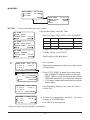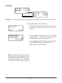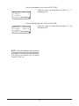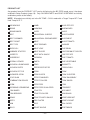
1
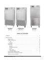
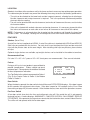
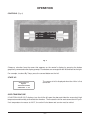
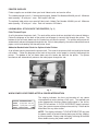
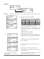
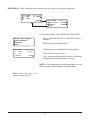
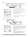
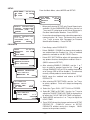
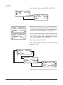
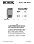
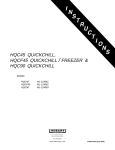
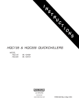
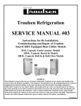
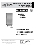
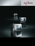
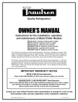
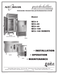
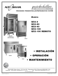
HQC45 & HQC90 QUICKCHILLERS & HQCF45 QUICKCHILLER-FREEZER MODEL HQC45 HQCF45 HQC90 ML-124066 ML-124067 ML-124068 701 S. RIDGE AVENUE TROY, OHIO 45374-0001 937 332-3000 www.hobartcorp.com FORM 34639 Rev. A (Sept. 2001) Model HQC45 QuickChiller With Legs Model HQCF45 QuickChiller-Freezer With Casters Model HQC90 QuickChiller With Casters TABLE OF CONTENTS GENERAL . . . . . . . . . . . . . . . . . . . . . . . . . . . . . . . . . . . . . . . . . . . . . . . . . . . . . . . . . . . . . . . . 4 INSTALLATION . . . . . . . . . . . . . . . . . . . . . . . . . . . . . . . . . . . . . . . . . . . . . . . . . . . . . . . . . . . . 5 UNCRATING . . . . . . . . . . . . . . . . . . . . . . . . . . . . . . . . . . . . . . . . . . . . . . . . . . . . . . . . . LEGS OR CASTERS . . . . . . . . . . . . . . . . . . . . . . . . . . . . . . . . . . . . . . . . . . . . . . . . . . . Legs . . . . . . . . . . . . . . . . . . . . . . . . . . . . . . . . . . . . . . . . . . . . . . . . . . . . . . . . . . . . . Casters . . . . . . . . . . . . . . . . . . . . . . . . . . . . . . . . . . . . . . . . . . . . . . . . . . . . . . . . . . LOCATION . . . . . . . . . . . . . . . . . . . . . . . . . . . . . . . . . . . . . . . . . . . . . . . . . . . . . . . . . . . FEATURES . . . . . . . . . . . . . . . . . . . . . . . . . . . . . . . . . . . . . . . . . . . . . . . . . . . . . . . . . . . Shelves . . . . . . . . . . . . . . . . . . . . . . . . . . . . . . . . . . . . . . . . . . . . . . . . . . . . . . . . . . Recommended Pans . . . . . . . . . . . . . . . . . . . . . . . . . . . . . . . . . . . . . . . . . . . . . . . Probes . . . . . . . . . . . . . . . . . . . . . . . . . . . . . . . . . . . . . . . . . . . . . . . . . . . . . . . . . . . Door Switch . . . . . . . . . . . . . . . . . . . . . . . . . . . . . . . . . . . . . . . . . . . . . . . . . . . . . . . Fan Door Switch . . . . . . . . . . . . . . . . . . . . . . . . . . . . . . . . . . . . . . . . . . . . . . . . . . . ELECTRICAL CONNECTIONS . . . . . . . . . . . . . . . . . . . . . . . . . . . . . . . . . . . . . . . . . . . INSTALLATION OF REMOTE ALARM . . . . . . . . . . . . . . . . . . . . . . . . . . . . . . . . . . . . . INSTALLATION CHECKOUT . . . . . . . . . . . . . . . . . . . . . . . . . . . . . . . . . . . . . . . . . . . . HOBART CORPORATION, 2001 –2– 5 5 5 5 6 6 6 6 6 6 6 7 7 7 OPERATION . . . . . . . . . . . . . . . . . . . . . . . . . . . . . . . . . . . . . . . . . . . . . . . . . . . . . . . . . . . . . . . . 8 CONTROLS . . . . . . . . . . . . . . . . . . . . . . . . . . . . . . . . . . . . . . . . . . . . . . . . . . . . . . . . . . . . . 8 START-UP . . . . . . . . . . . . . . . . . . . . . . . . . . . . . . . . . . . . . . . . . . . . . . . . . . . . . . . . . . . . . . 8 OVER-TEMPERATURE . . . . . . . . . . . . . . . . . . . . . . . . . . . . . . . . . . . . . . . . . . . . . . . . . . . 8 PRINTER SUPPLIES. . . . . . . . . . . . . . . . . . . . . . . . . . . . . . . . . . . . . . . . . . . . . . . . . . . . . . 9 LOADING ROLL STOCK ONTO THE PRINTERS . . . . . . . . . . . . . . . . . . . . . . . . . . . . . . . 9 Plain Thermal Paper. . . . . . . . . . . . . . . . . . . . . . . . . . . . . . . . . . . . . . . . . . . . . . . . . . . 9 Adhesive-Backed Label Stock for Optional Label Printer . . . . . . . . . . . . . . . . . . . . . 9 WHEN POWER IS RESTORED AFTER A POWER INTERRUPTION . . . . . . . . . . . . . . . 9 MAIN MENU — Chill: BY TEMP . . . . . . . . . . . . . . . . . . . . . . . . . . . . . . . . . . . . . . . . . . . . 10 MAIN MENU — Chill: BY TIME . . . . . . . . . . . . . . . . . . . . . . . . . . . . . . . . . . . . . . . . . . . . . 12 MAIN MENU — Chill: BY PROD . . . . . . . . . . . . . . . . . . . . . . . . . . . . . . . . . . . . . . . . . . . . 14 PRODUCT LIST . . . . . . . . . . . . . . . . . . . . . . . . . . . . . . . . . . . . . . . . . . . . . . . . . . . . . . . . . 16 HOLD PROD . . . . . . . . . . . . . . . . . . . . . . . . . . . . . . . . . . . . . . . . . . . . . . . . . . . . . . . . . . . 17 DEFROST . . . . . . . . . . . . . . . . . . . . . . . . . . . . . . . . . . . . . . . . . . . . . . . . . . . . . . . . . . . . . 18 PRINT . . . . . . . . . . . . . . . . . . . . . . . . . . . . . . . . . . . . . . . . . . . . . . . . . . . . . . . . . . . . . . . . . 18 SETUP — PRODUCTS . . . . . . . . . . . . . . . . . . . . . . . . . . . . . . . . . . . . . . . . . . . . . . . . . . . 19 SETUP — USERS . . . . . . . . . . . . . . . . . . . . . . . . . . . . . . . . . . . . . . . . . . . . . . . . . . . . . . . 20 SYS PAR . . . . . . . . . . . . . . . . . . . . . . . . . . . . . . . . . . . . . . . . . . . . . . . . . . . . . . . . . . . . . . 21 CLOCK . . . . . . . . . . . . . . . . . . . . . . . . . . . . . . . . . . . . . . . . . . . . . . . . . . . . . . . . . . . . 22 PROBES . . . . . . . . . . . . . . . . . . . . . . . . . . . . . . . . . . . . . . . . . . . . . . . . . . . . . . . . . . . 23 TEMPS IN °F . . . . . . . . . . . . . . . . . . . . . . . . . . . . . . . . . . . . . . . . . . . . . . . . . . . . . . . 23 LOGGING . . . . . . . . . . . . . . . . . . . . . . . . . . . . . . . . . . . . . . . . . . . . . . . . . . . . . . . . . . 23 REMOTE ALARM . . . . . . . . . . . . . . . . . . . . . . . . . . . . . . . . . . . . . . . . . . . . . . . . . . . . 24 ALARMS . . . . . . . . . . . . . . . . . . . . . . . . . . . . . . . . . . . . . . . . . . . . . . . . . . . . . . . . . . . 25 MODE Parameters — CHILL . . . . . . . . . . . . . . . . . . . . . . . . . . . . . . . . . . . . . . . . . . . 26 MODE Parameters — SOFT CHILL . . . . . . . . . . . . . . . . . . . . . . . . . . . . . . . . . . . . . 27 MODE Parameters — FREEZE . . . . . . . . . . . . . . . . . . . . . . . . . . . . . . . . . . . . . . . . . 28 BUZZER . . . . . . . . . . . . . . . . . . . . . . . . . . . . . . . . . . . . . . . . . . . . . . . . . . . . . . . . . . . 29 FACTORY PRESETS . . . . . . . . . . . . . . . . . . . . . . . . . . . . . . . . . . . . . . . . . . . . . . . . . 29 GLOSSARY . . . . . . . . . . . . . . . . . . . . . . . . . . . . . . . . . . . . . . . . . . . . . . . . . . . . . . . . . . . . 30 COMMUNICATION WITH SmartChill™ . . . . . . . . . . . . . . . . . . . . . . . . . . . . . . . . . . . . . . . . . . 31 MAINTENANCE . . . . . . . . . . . . . . . . . . . . . . . . . . . . . . . . . . . . . . . . . . . . . . . . . . . . . . . . . . . . 32 CLEANING . . . . . . . . . . . . . . . . . . . . . . . . . . . . . . . . . . . . . . . . . . . . . . . . . . . . . . . . . . . . . CONDENSER COIL . . . . . . . . . . . . . . . . . . . . . . . . . . . . . . . . . . . . . . . . . . . . . . . . . . . . . . EVAPORATOR COIL, CONDENSATE LOOP AND CONDENSATE REMOVAL PAN . ERROR MESSAGES . . . . . . . . . . . . . . . . . . . . . . . . . . . . . . . . . . . . . . . . . . . . . . . . . . . . . MAINTENANCE PROGRAM . . . . . . . . . . . . . . . . . . . . . . . . . . . . . . . . . . . . . . . . . . . . . . . –3– 32 32 32 32 32 Installation, Operation, Use and Care of HQC45 & HQC90 QuickChillers & HQCF45 QuickChiller-Freezer SAVE THESE INSTRUCTIONS GENERAL The HQC45 QuickChiller is designed for rapid chilling of 45 pounds of food (9 pounds of food per pan in five 12" x 20" x 21⁄2" pans or five 18" x 26" sheet pans) from 150°F to 37°F in approximately 90 minutes. The rapid chilling process preserves food quality, texture and nutritional value for up to 5 days. As many as 5 chill cycles can be handled per 8 hour shift. At the end of a chill cycle, the chiller automatically goes into Hold mode at normal refrigerator temperatures, enabling overnight chilling. The HQCF45 QuickChiller-Freezer is designed to chill exactly like the HQC45 and it can also freeze product down to – 20°F. Freezing time varies according to the initial and final product temperatures as well as product type and quantity. Coated wire shelves can accommodate five full-size 12" x 20" x 21⁄2" pans or five 18" x 26" sheet pans. The HQC90 QuickChiller is designed for rapid chilling of 90 pounds of food (9 pounds of food per pan in ten 12" x 20" x 21⁄2" pans) from 150°F to 37°F in approximately 90 minutes. Optional coated wire shelves can accommodate ten full-size 12" x 20" x 21⁄2" pans or five 18" x 26" x 21⁄2" pans. Chill and Freeze times are dependent upon product type, thickness, density, thermal conductivity, and type of covering. For best results, approximately 9 pounds of product per 12" x 20" x 21⁄2" pan or 18" x 26" sheet pan is recommended. If more product per pan is being chilled, the time required to chill will be increased. Cabinets are provided with a junction box in the lower section which allows for permanent, hard-wire connection. Stainless steel legs or casters are available accessories. The durable stainless steel interior has coved corners for ease of cleaning. The exterior sides, front, and back are stainless steel. Left or right door swing is available on order and cannot be changed in the field. Compressors supplied by Hobart are rated 11⁄4 HP on HQC45 and HQCF45. Compressors are rated 13⁄4 HP on HQC90. Refrigerant is R404A. Remote refrigeration system or water cooled refrigeration system are optional. Location of RS232 port for SmartChill is standard in front behind the printer door and optional at the rear. The SmartChill™ controller provides the ability to: • Select the chill mode: By Product, By Time or By Temperature (Chill or Freeze, model HQCF45). • Display the current air and product temperatures and time. • Monitor product temperature with three smart probes to reduce chances of freezing. • Select Soft Chill to reduce the chances of freezing in the final phase of chilling. • Provide service diagnostics to quickly check machine functions and control circuitry. • Send Chill Cycle data via RS232 port to SmartChill™ computer software, state-of-the-art HACCP data management. The standard printer provides the ability to: • Print data from the last or any chill cycle with time, date, and temperature information. • Charts chill temperatures vs. time at intervals that can be set by the supervisor. An optional second printer can print a condensed ‘Label’ type of report with Product and User info. • Printers provide HACCP reporting of chill data. –4– INSTALLATION Before installing, check the electrical service to make sure it agrees with the electrical specifications on the rating plate located inside the cabinet. UNCRATING Immediately after unpacking, check for possible shipping damage. If the chiller is found to be damaged, save the packaging material and contact the carrier within 15 days of delivery. DO NOT LAY THE CHILLER ON ITS FRONT, BACK OR SIDES. EXERCISE EXTREME CARE WHEN REMOVING THE CRATE BOTTOM ESPECIALLY WHEN THE LAST SHIPPING BOLT IS REMOVED. CABINET MUST BE PROPERLY BLOCKED AND STABLE. Cabinet is bolted onto a wood shipping base from underneath using the Threaded Hole (Fig.1). Remove shipping bolts. LEGS OR CASTERS The HQC45, HQCF45 and HQC90 must be installed with legs or casters. WARNING: THE CABINET MUST BE BLOCKED AND STABLE BEFORE INSTALLING THE LEGS OR CASTERS. Legs (Optional) To install the legs, raise up and block the cabinet a minimum of 7" from the floor and thread the legs into the threaded holes on the bottom of the cabinet. The chiller must be level to operate properly. Turn the adjustable feet in or out as required to level the chiller front-to-back and side-to-side (Fig. 1). Casters (Optional) Casters may be supplied for use on self-contained units. The swivel casters with brake should be installed in front; casters without brake, in rear (Fig. 2). Caster equipped chillers should be located on a level floor. PL-50909 Fig. 1 Fig. 2 –5– LOCATION Good air circulation at the condenser coil in the lower section is necessary to provide proper operation. The cabinet may be located in any one of the following three ways to assure satisfactory performance. • The unit can be situated so the lower back section is open to room air, allowing free air discharge. No side clearance and no top clearance is required. This is the preferred situation and provides the most effective cooling. • The unit can be provided with no side clearance, two inches of clearance at the rear, and six inches of clearance above. • If the unit is situated with no back clearance and no top clearance, it is necessary to provide either five inches of clearance on each side or ten inches of clearance on one side of the cabinet. NOTE: Performance is enhanced when the air going into the condenser coil through the lower front section is cool. For example, locating the chiller adjacent to an oven would not be recommended. FEATURES Shelves (Set of Five) A set of five shelves is optional on HQC90. A set of five shelves is standard with HQC45 and HQCF45. Shelf clips are packed with the shelves. For each shelf, insert two front shelf clips and two rear shelf clips into the pilaster slots at the same height. After installing shelf clips on pilasters, place shelves on clips. Optional single shelves are available; up to eight shelves can be installed in the cabinet at one time. Recommended Pans Full size 12" x 20" x 21⁄2" pans or 18" x 26" sheet pans are recommended. Pans are not included. Probes During a chill cycle, insert probes in pans of food to monitor temperatures. Probes should not touch bottom of pan. Place probe in the middle of the food for best temperature indication. The Top Probe in the cabinet corresponds to Probe 1 (Fig. 3); the Center Probe is Probe 2; the Bottom Probe is Probe 3. CHILLING AIR: 14 °F 156 °F 3 1 159 °F 2 154 °F 0:00:03 ADD/REMOVE Fig. 3 Door Switch When the door is opened, the door switch shuts off fans and DOOR OPEN displays. If the door is open for 30 seconds, the refrigerant valve closes. If the door is open for 120 seconds (or the DOOR OPEN time setting on page 25), a buzzer sounds. After the door closes, timer and chiller operations resume. Fan Door Switch A fan door switch also shuts the fans and refrigerant valve off if the metal fan grill is not properly fastened in place. A notice displays: WARNING !!! FAN DOOR IS OPEN. CALL HOBART SERVICE FOR REPAIR. If the operator and supervisor cannot shut the interior fan door, contact Hobart Service. The chiller will not operate with the fan door open. –6– ELECTRICAL CONNECTIONS Line voltage supplied to the cabinet junction box must not be affected by the operation of other electrical equipment. Junction box is located at the rear of the lower section. The rear compressor cover is maintained in place with Velcro. Pull to remove it. WARNING: ELECTRICAL AND GROUNDING CONNECTIONS MUST COMPLY WITH THE APPLICABLE PORTIONS OF THE NATIONAL ELECTRICAL CODE AND/OR OTHER LOCAL ELECTRICAL CODES. WARNING: DISCONNECT ELECTRICAL POWER SUPPLY AND PLACE A TAG AT THE DISCONNECT SWITCH INDICATING THAT YOU ARE WORKING ON THE CIRCUIT. The circuit should be protected with a Dual Element Time-Delay Fuse or Inverse Time Circuit Breaker. INSTALLATION OF REMOTE ALARM (Optional) The chiller provides a connection for a remote alarm that operates when the buzzer sounds on completion of a chill cycle. Connect to terminals on terminal block (# 5 and # 6 in the upper section of the chiller) per the wiring diagram and these restrictions: 1. Maximum remote alarm rating: 120 – 240 Volts at 2 amps resistive or 100 watt incandescent lamp. 2. Connection must be made of 600 volt insulated wire suitable for supply voltage. Do not use bell wire, lamp cord or similar type wire. INSTALLATION CHECKOUT The self-contained refrigeration system (when equipped) is shipped fully charged with refrigerant and requires only proper electrical connections. Remote refrigeration systems must be installed, connected and charged by others. After proper electrical connections are made, place the switch next to the control in the On position. –7– OPERATION CONTROLS (Fig. 4) MAIN MENU BY TEMP BY TIME 08:05:01 BY PROD MORE Fig. 4 Choose a selection from the menu that appears on the control’s display by pressing the button graphically connected to the display prompt. Four buttons are arranged on the left and four on the right. For example, to select By Temp, press the second button on the left. START-UP SmartChill HQC90 INITIALIZING VERSION 1.00 The screen at left is displayed when the chiller is first turned on. OVER TEMPERATURE If CAUTION HI AIR 150°F displays, turn the chiller off, open the door and allow the excessively high temperature and humidity to evacuate the chamber. Then restart the chiller and resume the chill cycle. If air temperature increases to 160°F, the unit will shut down and service must be called. –8– PRINTER SUPPLIES Printer supplies are available from your local Hobart sales and service office. The standard printer uses 21/4" thermal printer paper, Hobart Part Number 434409, per roll. Minimum order quantity: 50 rolls per 1 case. Roll length is 80 feet. The optional label printer uses peel-off label stock, Hobart Part Number 434408, per roll. Minimum order quantity: 50 rolls per 1 case. Each roll contains 225 labels. LOADING ROLL STOCK ONTO THE PRINTERS (Fig. 5) Plain Thermal Paper A roll is placed on the printer shaft. The ends of the printer shaft are installed in the two roll holders. Follow the diagram on the back of the printer so the paper is correctly fed through the printer. The bottom of the roll feeds down over the feeder bar and into the printer. The printer mechanism will automatically advance the paper through the slot. If this is done properly, the correct side of the thermal paper can be activated by the thermal printer head. Adhesive-Backed Label Stock for Optional Label Printer A roll of label stock is placed on the printer shaft. The ends of the printer shaft are installed in the two roll holders. Follow the diagram on the back of the printer so the paper is correctly fed through the printer. The bottom of the roll feeds down over the feeder bar and into the printer. The printer mechanism will automatically advance the label paper through the slot. PL-41530 Fig. 5 WHEN POWER IS RESTORED AFTER A POWER INTERRUPTION CYCLE INTERRUPTED: FROM 3/15/01 10:17 UNTIL 3/15/01 13:22 CONT. CHILLING OK The display indicates the time and duration of any power interruption that occurs during a Chill cycle. The operator can make appropriate decisions about food stored in the chiller. Press OK to continue. A CYCLE INTERRUPT report is printed. Then, the system resumes at the previous activity. Return to the Main Menu for any other action. NOTE: The display indicates CYCLE INTERRUPTED any time the power switch is turned off and on during any chilling, holding, or freezing mode. Always stop chilling by returning to the Main Menu before turning the power switch off. –9– MAIN MENU MAIN MENU BY TEMP BY TIME 08:05:01 BY PROD MAIN MENU HOLD PROD DEFROST BACK MORE 08:06:01 PRINT SETUP BY TEMP — Chill Cycle is complete when any (or all) product probe(s) reaches the Target Temp. BY TEMPERATURE TYPE: CHILL ↓TARGET TEMP: 37 °F↑ MAIN START From the Main Menu, select BY TEMP. • BY TEMPERATURE TYPE: SOFT CHILL ↓TARGET TEMP: 37 °F↑ MAIN START Select the Type: CHILL, SOFT CHILL or FREEZE*. SERIES BY TEMP HQC, HQCF CHILL HQC, HQCF SOFT CHILL HQCF BY TEMPERATURE TYPE: FREEZE ↓TARGET TEMP: 0 °F↑ MAIN START ❄ CHILLING AIR: 14 °F 1 159 °F 3 2 154 °F 0:00:03 ADD/REMOVE SELECT PROBE: 1 159 °F 3 2 154 °F 0:00:07 CONTINUE CHILLING AIR: 14 °F 1 159 °F 156 °F 3 2 154 °F 0:00:19 ADD/REMOVE CHILLING 1 41 °F 2 44 °F 1:16:01 AIR: 14 °F DONE 3 MUTE * Some chill types are not available on all models. FREEZE FACTORY PRESET TARGET TEMP 37°F 37°F 0°F RANGE 33 TO 40° F** 33 TO 40° F** – 22 to 28°F ** Range can be extended to 55°F by supervisor if desired — see page 26. • To adjust the TARGET TEMP: Press ↓ or ↑. • Insert probes in product — smart probes sense temperature of product and are automatically selected. • Close the door. • To begin Chilling, select START. (MAIN returns to the Main Menu.) • To add more product while chilling: Open door; insert probe in product; close door; press ADD/REMOVE. • If any probes are OFF, select the desired probe(s). • Press CONTINUE. • The chill time displays in the lower left corner — Hr: Min: Sec. ☛ A probe has reached the target temperature. • Press MUTE or select the ‘done’ probe’s number to silence the buzzer. (This step is repeated as each probe reaches the target temperature; see next page.) – 10 – CHILLING AIR: 14 °F 1 41 °F DONE 3 2 44 °F 1:16:01 ADD/REMOVE • Press ADD/ REMOVE. • If all probes are ‘done,’ the display goes to HOLDING. SELECT PROBE: 1 41 °F DONE 3 2 44 °F 1:16:08 CONTINUE • Select the ‘done’ probe’s number to remove it. • Remove all product associated with the ‘done’ probe. • Select any other probe’s number to stop cycle and remove it. Answer YES or NO. SELECT PROBE: 1 39 °F REMOVE 3 2 44 °F 1:16:28 CONTINUE HOLDING AIR: 37 °F 1 DONE DONE 3 2 DONE 1:16:01 ADD/REMOVE STOP CYCLE ON #2 REMOVE PRODUCT? NO YES • Press CONTINUE. • Select NONE to continue chilling with no report. • Or, select RECORD to print a Chill Report on Probe #3. Refer to the alternate Print Probe menu at the bottom of this page. • Repeat from ☛ as each probe reaches the target temperature. • When all probes are done, return to the Main Menu. • If equipped with the optional label printer, an alternate Print Probe menu, shown at left, permits the choice of printing . . . RECORD, LABEL or BOTH . . . types of reports. PRINT PROBE #3 NONE RECORD CHILLING AIR: 13 °F 1 39 °F 3 2 44 °F 1:17:42 ADD/REMOVE CHILLING 1 DONE 2 40 °F 1:19:02 AIR: 14 °F 3 MUTE PRINTING PLEASE WAIT... PRINT PROBE #3 RECORD LABEL NONE BOTH – 11 – MAIN MENU MAIN MENU BY TEMP BY TIME 08:05:01 BY PROD MAIN MENU HOLD PROD DEFROST BACK MORE 08:06:01 PRINT SETUP BY TIME — Timer counts down until cycle is done. BY TIME TYPE: CHILL ↓CYCLE TIME: 01:30↑ MAIN START From the Main Menu, select BY TIME. • BY TIME TYPE: SOFT CHILL ↓CYCLE TIME: 01:30↑ MAIN START BY TIME TYPE: FREEZE ↓CYCLE TIME: 01:30↑ MAIN START ❆ DOOR OPEN AIR: 14 °F 1 159 °F 156 °F 3 2 154 °F 1:30:00 STOP/RESET HOLDING 1 39 °F 2 44 °F 0:00:00 AIR: 14 °F 42 °F 3 MUTE SERIES BY TEMP INITIAL TIME SETTING TIME RANGE HQC, HQCF CHILL 01:30 00:01 TO 24:00 01:30 00:01 TO 24:00 01:30 00:01 TO 24:00 HQC, HQCF SOFT CHILL HQCF FREEZE • To adjust the CYCLE TIME: Press ↓ or ↑. • To begin Chilling, select START. (MAIN returns to the Main Menu.) • Close the door. • Probes display temperatures but have no effect on the chilling process. • Select STOP / RESET to obtain these menu items: ° ADD 30 MINUTES adds 30 minutes to the timer. ° RESET TIMER re-starts at the original time setting. ° CONTINUE resumes the cycle at the time remaining. ° STOP allows a report to be printed and then returns to Main Menu. • Time Remaining displays in the lower left corner — Hr: Min: Sec. BY TIME ADD 30 MINUTES RESET TIMER STOP CONTINUE CHILLING AIR: 14 °F 1 159 °F 156 °F 3 2 154 °F 1:29:57 STOP/RESET Select the Type: CHILL, SOFT CHILL or FREEZE*. ☛ The timer has counted down to 0:00:00. The chiller changes to HOLDING Mode. • Press MUTE to silence buzzer. * Some chill types are not available on all models. – 12 – HOLDING AIR: 14 °F 1 39 °F 42 °F 3 2 44 °F 0:00:11 STOP/RESET • The total time since the cycle was finished is displayed — Hr: Min: Sec. • Remove all chilled product. • Press STOP/ RESET. • Select NONE to continue without printing. • Select RECORD to print a Chill Report. If equipped with the optional label printer, refer to the alternate Print menu below. NOTE: Chilling BY TIME does not retain Product Probe temperature data in memory and will not print TEMP vs. TIME information. • After printing or selecting NONE, return to Main Menu. • If equipped with the optional label printer, an alternate Print menu, shown at left, permits the choice of printing . . . RECORD, LABEL or BOTH . . . types of reports. PRINT NONE RECORD PRINTING PLEASE WAIT... MAIN MENU PRINT NONE RECORD LABEL BOTH – 13 – MAIN MENU MAIN MENU BY TEMP BY TIME 08:05:01 BY PROD MAIN MENU HOLD PROD DEFROST BACK MORE 08:06:01 PRINT SETUP BY PROD — Recalls programmed chill parameters for the product, either BY TEMP or BY TIME. From the Main Menu, select BY PROD. SELECT USER: ↓TIM SMITH BACK • If two or more users have been entered, use the ↓ or ↑ keys until the users name is displayed. Then press SELECT. • The two products displayed are the most recently chilled products. The ↓ key will access the next enabled product from the product list, etc. • Press the key beside the product name to recall that product’s chill parameters and begin chilling. ↑ SELECT SELECT PRODUCT: ↑CHICKEN PARTS ↓SOUP VEGETABLE MAIN MENU (MAIN returns to the Main Menu. NOTE: If the product you wish to select is on the Product List on page 16 but is not available from the Select Product screen, it needs to be enabled. The Supervisor should refer to Setup Products, page 19. – 14 – If the selected product was set to chill BY TEMP: • CHILLING AIR: 14 °F 1 159 °F 3 2 154 °F 0:00:03 ADD/REMOVE Follow the cycle run information on pages 10 – 11 beginning at ❄. If the selected product was set to chill BY TIME: CHILLING AIR: 14 °F 1 159 °F 156 °F 3 2 154 °F 1:29:57 STOP/RESET • Follow the cycle run information on pages 12 – 13 beginning at ❆. NOTE: If the chill parameters for the product you selected do not chill the way you want, the product’s chill settings need to be edited. The Supervisor should refer to Setup Products, page 19. – 15 – PRODUCT LIST Any product from the PRODUCT LIST can be chilled using the BY PROD mode, once it has been enabled in Setup Products (page 19). Only CHICKEN PARTS and SOUP VEGETABLE are initially enabled as preset at the factory. NOTE: All products are initially set in the BY TEMP – CHILL mode with a Target Temp of 37°F and Hold Temp of 37°F. ASPARAGUS LAMB SALAD POTATO BEANS LASAGNA SANDWICHES BEANS BAKED LIVER SAUCE BEEF MACARONI & CHEESE SAUCE CHEESE BEEF CREAMED MACARONI & GROUND BEEF SAUCE MEAT BEEF ROAST MEAT SAUCE TOMATO BEEF TIPS MEAT GROUND SAUSAGE BROCCOLI MEAT LOAF SOUP BEAN CABBAGE STUFFED MEAT SLICED SOUP CREAM OF CELERY CARROTS MEAT WITH SAUCE SOUP POTATO CASSEROLE OATMEAL SOUP TOMATO CEREAL COOKED PASTA SOUP VEGETABLE CHICKEN & DUMPLINGS PEAS SPAGHETTI CHICKEN PARTS PEPPERS STUFFED STARCH DISH CHICKEN POT PIE PORK STEAK CHOWDER CORN PORK CHOPS STEAK CHOPPED COLE SLAW POTATO MASHED STEAK SALISBURY COMBINATION DISHES POTATO SLICED STEAK SWISS CORN POTATOES STEW DRESSING CORNBREAD POTATOES SCALLOPED STEW BEEF FISH BAKED POULTRY TACO MEAT FISH BREADED POULTRY SLICED TUNA SALAD GRAVY POULTRY WITH SAUCE TURKEY BREAST GRITS PRE PLATES TURKEY ROAST HAM RICE VEAL CHOPS JELLO ROAST WHOLE VEGETABLES – 16 – HOLD PROD — After Chilling or when selected, runs the chiller like a regular refrigerator. MAIN MENU BY TEMP BY TIME 08:05:01 BY PROD MAIN MENU HOLD PROD DEFROST BACK MORE 08:06:01 PRINT SETUP From the Main Menu, select MORE and HOLD PROD. SELECT HOLD MODE: REFRIGERATOR FREEZER BACK HOLDING 1 37 °F 2 37 °F 0:00:04 AIR: 34 °F 37 °F 3 EXIT • Select REFRIGERATOR or FREEZER mode, if available. (BACK returns to the Main Menu.) (Temperatures are indicated for air and probes.) (Timer indicates the run time.) (EXIT returns to the Main Menu; however, Hold mode continues until another selection is made.) NOTE: HOLD mode does not retain temperature vs. time data in memory; printed reports are not available. NOTE: Freezer Hold mode is only available on Model HQCF45. – 17 – DEFROST MAIN MENU BY TEMP BY TIME NOTE: DEFROST starts automatically after 6 hours of chilling but only if operating in Holding mode. 08:05:01 BY PROD MAIN MENU HOLD PROD DEFROST BACK MORE 08:06:01 PRINT SETUP From the Main Menu, select MORE and DEFROST. READY TO DEFROST REMOVE FOOD CANCEL • (CANCEL returns to the Main Menu.) START DEFROSTING COIL 12 °F TIME REMAINING 19:52 EXIT DEFROST NOT REQUIRED To begin Defrosting, remove food and select START. • The DEFROST cycle runs 20 minutes or until the Coil Temperature reaches 50°F. (EXIT returns to the Main Menu.) • If DEFROST NOT REQUIRED is displayed, return to Main Menu is automatic. PRINT — Once a chill cycle is done, data can be printed. MAIN MENU BY TEMP BY TIME 08:05:01 BY PROD MAIN MENU HOLD PROD DEFROST BACK MORE 08:06:01 PRINT SETUP From the Main Menu, select MORE and PRINT. PRINT CYCLE #____ PROBE #_ MM/DD HH:mm→ ←BACK SELECT NEXT→ MAIN MENU PRINT PRINT PROBE #_ RECORD LABEL NONE BOTH • The last chill cycle displays Probe # (if BY TEMP), MM/DD (= month/day), and HH:mm (= hour:minute). Probe # will not display if the chill cycle was BY TIME. • Select the Cycle you want to print by pressing ← (for previous) and → (for next). • Press PRINT. (MAIN returns to the Main Menu.) • To print, select RECORD, LABEL or BOTH. After printing, the display returns to the Main Menu. (NONE returns to the Main Menu.) – 18 – SETUP From the Main Menu, select MORE and SETUP. MAIN MENU BY TEMP BY TIME 08:05:01 BY PROD MORE MAIN MENU HOLD PROD DEFROST BACK 08:06:01 PRINT SETUP SELECT SUPERVISOR: ↓PRESET SUPERVISOR↑ ↓PASSWORD (PIN): 00↑ CANCEL ENTER • When you first enter SETUP, only Preset Supervisor is available. On the PASSWORD (PIN) line, use the ↓ or ↑ keys until 57 is displayed as the Preset Supervisor’s Personal Identification Number. Press ENTER. SELECT SUPERVISOR: ↓TIM SMITH ↑ ↓PASSWORD (PIN): 07↑ CANCEL ENTER • If users have already been setup, select the supervisor’s name using the ↓ or ↑ keys. On the next line, use the ↓ or ↑ keys to enter their Password (or Personal Identification Number). Press ENTER. • From Setup, select PRODUCTS. • Select ENABLE / DISABLE to choose what products are enabled from the Product List. Only an enabled product is available to chill BY PROD. Go to ☞. • Select EDIT SETTINGS to adjust chill parameters for any product that has already been enabled. Go to ➢. PRODUCTS SETUP PRODUCTS USERS MAIN MENU 09:04:11 SYS PAR SETUP PRODUCTS: ENABLE/DISABLE EDIT SETTINGS BACK PRODUCT SELECTION: ↓A S P A R A G U S ↑ ENABLED: NO BACK ↓A S P A R A G U S TYPE: CHILL ↓TARGET TEMP: BY TEMP ↓A S P A R A G U S ↓HOLD TEMP: BACK ↑ 37°F↑ MORE ↑ 37 °F↑ CANCEL SAVE (BACK returns to SETUP.) ☞ After selecting ENABLE / DISABLE, use the ↓ or ↑ to keys to select a product from the list. Press change ENABLED: NO to YES to enable the product or to change YES to NO to disable it. The two most recently chilled products cannot be disabled. • BACK saves the ‘enabled’ and returns to SETUP PRODUCTS. ➢ After selecting EDIT SETTINGS, use the ↓ or ↑ keys to select a product. Finish all ⊗ steps to change any setting(s). ⊗ Select the Type: CHILL, SOFT CHILL or FREEZE. ⊗ Select BY TEMP or BY TIME. Use the ↓ or ↑ keys to adjust the TARGET TEMP if BY TEMP is displayed, or to adjust the CYCLE TIME if BY TIME is displayed. ⊗ Select MORE and use the ↓ or ↑ keys to adjust the HOLD TEMP. ⊗ Press SAVE to keep the changes and return to SETUP PRODUCTS. (CANCEL returns to SETUP PRODUCTS without saving the changes. BACK returns to the previous screen). – 19 – SETUP From the Main Menu, select MORE and SETUP. MAIN MENU BY TEMP BY TIME 08:05:01 BY PROD MAIN MENU HOLD PROD DEFROST BACK MORE 08:06:01 PRINT SETUP SELECT SUPERVISOR: ↓PRESET SUPERVISOR↑ ↓PASSWORD (PIN): 00↑ CANCEL ENTER • When you first enter SETUP, only Preset Supervisor is available. On the PASSWORD (PIN) line, use the ↓ or ↑ keys until 57 is displayed as the Preset Supervisor’s Personal Identification Number. Press ENTER. SELECT SUPERVISOR: ↓TIM SMITH ↑ ↓PASSWORD (PIN): 07↑ CANCEL ENTER • If users have already been setup, select the supervisor’s name using the ↓ or ↑ keys. On the next line, use the ↓ or ↑ keys to enter their Password (or Personal Identification Number). Press ENTER. • From Setup, select USERS. USERS SETUP PRODUCTS USERS MAIN MENU 09:04:11 SYS PAR (MAIN MENU returns to the Main Menu.) • SETUP USERS: ADD DELETE ALL EDIT/DELETE BACK (DELETE ALL removes all users from the roster.) SELECT USER #1: ↓TIM SMITH ↑ EDIT DELETE BACK ENTER NAME: ↓_ BACK CANCEL Press ADD to add a user to the roster. The first user entered will automatically be given Supervisor status. ↑ (EDIT / DELETE allows a user’s security level or PIN to be revised or the user removed from the roster.) • To ENTER NAME: Press the ↓ or ↑ keys until the first letter of the user’s name is entered; then, press NEXT to move the cursor one space to the right. Repeat this step until all letters of the user’s name are entered. BACK moves the cursor one space to the left to edit. • Press ENTER to save the user’s name, as displayed. NEXT ENTER SETUP USER: SECURITY LEVEL:0PER ↓PASSWORD (PIN): 00↑ ENTER (CANCEL aborts the process.) • Press to change the security level from OPER to SUPV or from SUPV to OPER. See above, operator level security is only available after the first user is entered. • Use the ↓ or ↑ keys to select the user’s PASSWORD (PIN). • Press ENTER to save the user’s security level and PIN. Return to SETUP USERS. – 20 – SYS PAR • MAIN MENU BY TEMP BY TIME From the Main Menu, select MORE and SETUP. 08:05:01 BY PROD MAIN MENU HOLD PROD DEFROST BACK MORE SELECT SUPERVISOR: ↓PRESET SUPERVISOR↑ ↓PASSWORD (PIN): 00↑ CANCEL ENTER SELECT SUPERVISOR: ↓TIM SMITH ↑ ↓PASSWORD (PIN): 07↑ CANCEL ENTER SETUP PRODUCTS USERS MAIN MENU 08:06:01 PRINT SETUP • When you first enter SETUP, only Preset Supervisor is available. On the PASSWORD (PIN) line, use the ↓ or ↑ keys until 57 is displayed as the Preset Supervisor’s Personal Identification Number. Press ENTER. • If users have already been setup, select the supervisor’s name using the ↓ or ↑ keys. On the next line, use the ↓ or ↑ keys to enter their Password (or Personal Identification Number). Press ENTER. • From Setup, select SYS PAR. • Refer to the diagram below to access Sys Par settings (pages 22 – 29). 09:04:11 SYS PAR SYS PAR 1 09:07:31 CLOCK TEMPS IN °F PROBES LOGGING SETUP MENU MORE • SYS PAR 2 09:08:41 REMOTE ALARM MODE ALARMS BUZZER BACK FAC PRESETS From Sys Par 1, select MORE to access Sys Par 2. – 21 – • SYS PAR 1 09:07:31 CLOCK TEMPS IN °F PROBES LOGGING SETUP MENU MORE Access the Sys Par 1 menu as shown on page 21. SYS PAR 2 09:08:41 REMOTE ALARM MODE ALARMS BUZZER BACK FAC PRESETS • From Sys Par 1, select CLOCK. • Set the Month using the ↓ or ↑ keys. • Select NEXT to move to the Day field. • Set the Day using the ↓ or ↑ keys. • Select NEXT to move to the Year field. CLOCK SET CLOCK: Month 00:00↑ ↓00/00/00 ←BACK NEXT→ CANCEL ENTER SET CLOCK: Day 00:00↑ ↓00/00/00 ←BACK NEXT→ CANCEL ENTER (BACK returns to the previous screen.) SET CLOCK: Year 00:00↑ ↓00/00/00 ←BACK NEXT→ CANCEL ENTER SET CLOCK: Hour 00:00↑ ↓00/00/00 ←BACK NEXT→ CANCEL ENTER SET CLOCK: Minute ↓00/00/00 00:00↑ ←BACK NEXT→ CANCEL ENTER • Set the Year using the ↓ or ↑ keys. • Select NEXT to move to the Hour field. • Set the Hour using the ↓ or ↑ keys. • Select NEXT to move to the Minute field. • Set the Minutes using the ↓ or ↑ keys. (NEXT returns to the Month field.) (CANCEL returns to Main Menu without saving.) • Press ENTER to save the clock settings. – 22 – • Access the Sys Par 1 menu as shown on page 21. SYS PAR 1 09:07:31 CLOCK TEMPS IN °F PROBES LOGGING SETUP MENU MORE • SYS PAR 2 09:08:41 REMOTE ALARM MODE ALARMS BUZZER BACK FAC PRESETS From Sys Par 1, select PROBES. PROBES (Probe #’s 1 – 3 should be ON.) (Probe 4 is marked N/A; Not Available.) SELECT PROBE: 1 ON ON 3 2 ON N/A 4 CANCEL ENTER • Select any probes marked OFF to turn them ON. • Select ENTER to save any changes. (CANCEL returns to SYS PAR 1 without saving any changes.) TEMPS IN °F • SYS PAR 1 09:07:31 CLOCK TEMPS IN °F PROBES LOGGING SETUP MENU MORE From Sys PAR 1: (TEMPS IN °F indicates the control uses Fahrenheit temperatures.) • If TEMPS IN °C is displayed, select it to change the control from Celsius to Fahrenheit temperatures. • From Sys Par 1, select LOGGING. • Use the ↓ or ↑ keys to set the Data Logging Interval. This determines how often the data will be logged in memory. Range = 5, 10, 15, or 30 Minutes. • ENTER accepts the change and returns to SYS PAR 1. • CANCEL reverts back to the previously entered Data Logging Interval and returns to SYS PAR 1. LOGGING SELECT DATA LOGGING INTERVAL: ↓ 5 MINUTE(S) ↑ CANCEL ENTER – 23 – • Access the Sys Par 2 menu as shown on page 21. SYS PAR 1 09:07:31 CLOCK TEMPS IN °F PROBES LOGGING SETUP MENU MORE SYS PAR 2 09:08:41 REMOTE ALARM MODE ALARMS BUZZER BACK FAC PRESETS • From Sys Par 2, select REMOTE ALARM. • Yes closes the Remote Alarm circuit in the event of a printer error. (Use to change No to Yes, etc.) • Press • Yes closes the Remote Alarm circuit when the cycle ends. (Use to change No to Yes, etc.) • Press • Yes closes the Remote Alarm circuit whenever the door is open for longer than the ‘Door Open’ alarm time setting on page 25. (Use to change No to Yes, etc.) • Press • Yes closes the Remote Alarm circuit if temperature is sensed above the High Alarm Temperature limit or below the Low Alarm Temperature limit. (Use to change Yes to No, etc.) Refer to pages 26 and 28 to set the High Alarm and Low Alarm temperatures. • Press ACTIVATE REMOTE ALARM WHEN: POWER FAILURE =YES ENTER • Yes closes the Remote Alarm circuit when power is restored after a power interruption. (Use to change Yes to No, etc.) • Press ACTIVATE REMOTE ALARM WHEN: CYCLE RUNNING =NO ENTER • Yes closes the Remote Alarm circuit when a cycle is running. The Cycle Running option has a higher precedence and overrides all other remote alarm options, resetting them to NO. (Use to change Yes to No, etc.) REMOTE ALARM ACTIVATE REMOTE ALARM WHEN: PRINTER ERROR =NO ENTER ACTIVATE REMOTE ALARM WHEN: CYCLE ENDS =NO ENTER ACTIVATE REMOTE ALARM WHEN: DOOR OPEN =NO ENTER ACTIVATE REMOTE ALARM WHEN: HIGH/LOW TEMPS=YES ENTER to move to the next field. to move to the next field. to move to the next field. to move to the next field. to move to the next field. (Pressing • returns to . . . Printer Error.) Select ENTER to keep any changes and return to SYS PAR 2. – 24 – • Access the Sys Par 2 menu as shown on page 21. SYS PAR 1 09:07:31 CLOCK TEMPS IN °F PROBES LOGGING SETUP MENU MORE SYS PAR 2 09:08:41 REMOTE ALARM MODE ALARMS BUZZER BACK FAC PRESETS • From Sys Par 2, select ALARMS. • Use the ↓ or ↑ keys to adjust the DOOR OPEN setting. Range = 0, 30, 60, 90, 120, 150, 180, 210, 240 seconds. Refer to page 24. • Use the ↓ or ↑ keys to adjust the CLEAN COIL setting. Range = 30, 35, 40, 45, 50, 55, 60, 65, 70, 75, 80, 85, 90 days. The CLEAN COIL setting determines how many days the compressor will run before a display appears to remind you to clean the condenser coil. • Select ENTER to accept the displayed values and return to SYS PAR 2. ALARMS ALARM TIME SETTINGS: ↓DOOR OPEN=120 SECS↑ ↓CLEAN COIL=30 DAYS↑ ENTER – 25 – • Access the Sys Par 2 menu as shown on page 21. SYS PAR 1 09:07:31 CLOCK TEMPS IN °F PROBES LOGGING SETUP MENU MORE SYS PAR 2 09:08:41 REMOTE ALARM MODE ALARMS BUZZER BACK FAC PRESETS • From Sys Par 2, select MODE. • From Mode Parameters, select CHILL. MODE MODE PARAMETERS CHILL FREEZE SOFT CHILL BACK (BACK returns to SYS PAR 2.) CHILL CHILL MODE EDITOR ↓T A R G E T 3 7 °F↑ ←BACK NEXT→ CANCEL ENTER CHILL MODE EDITOR ↓AIR 10 ° F↑ ←BACK NEXT→ CANCEL ENTER CHILL MODE EDITOR ↓H O L D 3 7 ° F↑ ←BACK NEXT→ CANCEL ENTER CHILL MODE EDITOR ↓HIGH ALARM 45 °F↑ ←BACK NEXT→ CANCEL ENTER CHILL MODE EDITOR ↓LOW ALARM 32 °F↑ ←BACK NEXT→ CANCEL ENTER • • Select NEXT to move to the next field. (BACK returns to the previous field.) • Set the AIR Temp using the ↓ or ↑ keys. Range: [10°F to 40°F]. • • Select NEXT to move to the next field. Set the HOLD Temp using the ↓ or ↑ keys. Range: [10°F to 40°F]. • • Select NEXT to move to the next field. Set the HIGH ALARM Temp using the ↓ or ↑ keys. Range: [35°F to 60°F]. • • Select NEXT to move to the next field. Set the LOW ALARM Temp using the ↓ or ↑ keys. Range: [–30°F to 34°F]. • CHILL MODE EDITOR ↓CHILL MAX 40 °F↑ ←BACK NEXT→ CANCEL ENTER Set the TARGET Temp using the ↓ or ↑ keys. Range: [33°F to 40°F]. • Select NEXT to move to the next field. Set the CHILL MAX Temp using the ↓ or ↑ keys. Range: [40°F to 55°F]. (NEXT returns to the TARGET TEMP screen.) • NOTE: To extend the Target Temp range for Chill and Soft Chill modes, first change the CHILL MAX value. Then change the Target Temp. The Target Temp range can be extended to as high as 55°F. Select ENTER to keep any changes and return to Mode Parameters. (CANCEL retains the previous settings and returns to Mode Parameters.) – 26 – • SYS PAR 1 09:07:31 CLOCK TEMPS IN °F PROBES LOGGING SETUP MENU MORE Access the Sys Par 2 menu as shown on page 21. SYS PAR 2 09:08:41 REMOTE ALARM MODE ALARMS BUZZER BACK FAC PRESETS • From Sys Par 2, select MODE. • From Mode Parameters, select SOFT CHILL. MODE MODE PARAMETERS CHILL FREEZE SOFT CHILL BACK (BACK returns to SYS PAR 2.) SOFT CHILL — Assures against freezing by reducing air flow at end of cycle or by increasing air temp. [ % ] x Chill Time = Time when reduced air flow occurs. SOFT CHILL EDITOR ↓B Y T I M E 70%↑ ←BACK NEXT→ CANCEL ENTER Range: [10% to 90% ]. • Set the By Time % using the ↓ or ↑ keys. • Select NEXT to move to the next field. [_°F ] + Target Temp = Temp when reduced air flow occurs. Range: [ 5 to 20 °F]. SOFT CHILL EDITOR ↓BY TEMP 5 °F↑ ←BACK NEXT→ CANCEL ENTER • Set the By Temp degrees using the ↓ or ↑ keys. • Select NEXT to move to the next field. (BACK returns to the previous field.) [ 2nd Temp ] = Sets an alternate Air Temp during the Soft Chill cycle. SOFT CHILL EDITOR ↓2ND TEMP 28 °F↑ ←BACK NEXT→ CANCEL ENTER Range: [ 10°F to 40°F ]. Normal Air Temp (regular chill cycle) = 10 °F. • Set the 2nd Temp degrees using the ↓ or ↑ keys. (NEXT returns to the By Time field.) • Select ENTER to keep any changes and return to Mode Parameters. (CANCEL retains the previous settings and returns to Mode Parameters.) – 27 – • SYS PAR 1 09:07:31 CLOCK TEMPS IN °F PROBES LOGGING SETUP MENU MORE Access the Sys Par 2 menu as shown on page 21. SYS PAR 2 09:08:41 REMOTE ALARM MODE ALARMS BUZZER BACK FAC PRESETS • From Sys Par 2, select MODE. • From Mode Parameters, select FREEZE. MODE MODE PARAMETERS CHILL FREEZE SOFT CHILL BACK (BACK returns to SYS PAR 2.) FREEZE FREEZE MODE EDITOR ↓T A R G E T 0°F↑ ←BACK NEXT→ CANCEL ENTER FREEZE MODE EDITOR ↓AIR -25 °F↑ ←BACK NEXT→ CANCEL ENTER FREEZE MODE EDITOR ↓H O L D - 6 ° F↑ ←BACK NEXT→ CANCEL ENTER FREEZE MODE EDITOR ↓HIGH ALARM 32 °F↑ ←BACK NEXT→ CANCEL ENTER FREEZE MODE EDITOR ↓LOW ALARM -20 °F↑ ←BACK NEXT→ CANCEL ENTER • Set the TARGET Temp using the ↓ or ↑ keys. Range: [–22°F to 28°F]. • • Select NEXT to move to the next field. Set the AIR Temp using the ↓ or ↑ keys. Range: [–32°F to 20°F]. • Select NEXT to move to the next field. (BACK returns to the previous field.) • Set the HOLD Temp using the ↓ or ↑ keys. Range: [–32°F to 20°F]. • • Select NEXT to move to the next field. Set the HIGH ALARM Temp using the ↓ or ↑ keys. Range: [1°F to 35°F]. • • Select NEXT to move to the next field. Set the LOW ALARM Temp using the ↓ or ↑ keys. Range: [–30°F to 0°F]. (NEXT returns to the TARGET TEMP field.) • Select ENTER to accept the displayed values and return to Mode Parameters. (CANCEL retains the previous settings and returns to Mode Parameters.) NOTE: Freeze Mode is only available on model HQCF45. – 28 – • SYS PAR 1 09:07:31 CLOCK TEMPS IN °F PROBES LOGGING SETUP MENU MORE Access the Sys Par 2 menu as shown on page 21. SYS PAR 2 09:08:41 REMOTE ALARM MODE ALARMS BUZZER BACK FAC PRESETS • From Sys Par 2, select BUZZER. • Set the Volume [0 – 9 ] using the ↓ or ↑ keys. • Set the Tone [ 1 – 8 ] using the ↓ or ↑ keys. • Select ENTER to accept the displayed values and return to SYS PAR 2. • From Sys Par 2, select FAC PRESETS. • Select YES to restore system parameters to the factory preset values and return to SYS PAR 2. • Select NO to retain the present system parameters and return to SYS PAR 2. BUZZER BUZZER SETTINGS: ↓ VOLUME 9 ↑ ↓ TONE 3 ↑ ENTER FAC PRESETS RESET SYSTEM PARAMETERS TO FACTORY PRESETS? NO YES – 29 – GLOSSARY Alarms — Sets the buzzer intervals after Door is Open or when to be notified that the Compressor needs to be Cleaned. Buzzer — The control’s buzzer can have its volume and tone adjusted in the System Parameters. By Temp — Chill cycle that terminates when the probes reach the Target Temperature. By Time — Chill cycle that terminates after a set amount of time has lapsed. By Prod — Chill cycle that terminates after a particular product’s specified chill parameters are met (the parameters can be set either By Temp or By Time with specific cut-offs for a particular product. Chill — Chilling Cycle that may end with either Time or Temperature controlled events. (Also see Soft Chill or Freeze). Clock — Allows the Date and Time to be entered so the system’s clock correctly records chilling events. Cycle # — The system assigns a consecutive number to each Chill Cycle. Defrost — System Controlled Defrost occurs after six hours of chilling. The defrost will not begin during a chill cycle. The system waits until it is in Holding mode before starting the defrost cycle. The Defrost from the Main Menu is a manual defrost that will not run if selected and unneeded. The Defrost cycle requires about 20 minutes. Fac Presets — Factory Presets are system parameters that are set at the factory but can be changed by the supervisor. Freeze — This mode is only available on model HQCF45. It allows the product to be frozen down to a target temperature of 0°F (–18°C). The target temperature range available for freeze mode varies from –22°F to 28°F. Hold Prod — After a chill mode has been done or when selected from the Main Menu, the chiller will act like a regular refrigerator (or freezer on model HQCF45). Label — A condensed Chill Cycle Report that can be printed on adhesive-backed label stock by the optional second label printer. Logging — The time interval at which Chill Cycle data (temperature vs. time) is logged into memory for record purposes. This time interval can be modified in Sys Par (System Parameters) by the supervisor. The range of settings available for this time interval is: 5, 10, 15 or 30 minutes. Main Menu — The two initial menus available from the controller after the chiller is turned on. Mode — Basic chiller operating parameters are available from Sys Par in Setup mode. Chill mode parameters allow adjustment of the target temperature, the air temperature during chill mode, the hold mode temperature, the high alarm temperature, the low alarm temperature and the maximum chill mode target temperature. Soft Chill mode parameters apply a modification of some of the Chill settings during the final portion of the chill cycle if Soft Chill is selected. Soft Chill provides additional protection against freezing of surfaces. Freeze mode parameters (only available on model HQCF45) provide separate freeze settings that allow a direct hard freeze of product. – 30 – Oper — An Operator is a user who is allowed to operate the chiller and make reports of chill cycles performed. Print — Allows a report of any Chill Cycle and probe to be printed. Chillers equipped with the optional second printer can print the condensed ‘Label’ type of report. All Chillers can print the ‘Record’ type of report. Probe # — Each probe is numbered and its temperature vs. time is recorded for each probe # during every chill cycle and the record can be printed, either at the end of the chill cycle or subsequently. Product List — A list of products in system memory which can have individual chill parameters specifically set for each product (assuming that the product is already enabled). Refer to Setup Products. Record — Type of report that can be printed by all chillers. This report provides a record of time vs. temperature for a specific Probe and Chill Cycle. Remote Alarm — The chiller can be wired to a remote alarm which will close the remote alarm circuit in the event of one or more of the following situations: Printer Error, Cycle End, Door Open, High or Low Temperatures or Power Failure. If Cycle Running is chosen, the remote alarm circuit will close when a chill cycle is running and all other remote alarm settings are overridden (reset to NO). The supervisor can determine which events the remote alarm will signal by adjusting the settings in the Sys Par (System Parameters) section. Setup — Specific control settings that can be set by the supervisor which determine how the chiller will operate. Soft Chill — Type of chill process that moderates the temperatures and fan speed near the end of the chill cycle to provide less risk of freezing at the product’s surface. Supv — A Supervisor is a user who is allowed to identify the users and limit their access to system parameters, enable products to be selected, set specific product chill parameters and change system parameters. Sys Par — System Parameters are control settings that determine how the chiller will operate. These settings can be adjusted by the supervisor in Setup mode. Temps in °C — If so displayed on the Sys Par 1 screen, all temperatures will be recorded in °C (Celsius). Temps in °F — If so displayed on the Sys Par 1 screen, all temperatures will be recorded in °F (Fahrenheit). COMMUNICATION WITH SmartChill™ COMMUNICATING WITH COMPUTER During communication with the SmartChill™ program on a PC, the screen at left displays. PLEASE WAIT... – 31 – MAINTENANCE CLEANING Wash, rinse and sanitize the product probes before and after use as you would any food-contact utensil that measures temperature. Chiller surfaces of stainless steel should be wiped clean with a damp cloth or mild cleaning solution. DO NOT flush with running water. Avoid the use of solvents around plastic or painted areas; clean these with a damp cloth moistened with a solution of mild detergent and warm water. Clean hinge hardware with a chrome cleaner. Use a solution of warm water and baking soda to clean the gasket; then wipe with a soft cloth. Hinges may require occasional lubrication of the plastic cam. Do not use the top of the chiller for storage. CONDENSER COIL WARNING: DISCONNECT ELECTRICAL POWER SUPPLY BEFORE CLEANING ANY PARTS OF THE UNIT. The lower front compressor cover is attached with Velcro. Pull to remove. Check the condenser coil weekly. Air must be able to freely circulate through the condenser. This surface must be kept free of dirt and grease for proper system operation. Carefully clean dirt and lint from the condenser coil using a vacuum cleaner, whisk broom or soft brush; do not use a wire brush. CAUTION: Do not damage the condenser coil fins. Replace lower front compressor cover. Reconnect electrical power supply. EVAPORATOR COIL, CONDENSATE LOOP AND CONDENSATE REMOVAL PAN WARNING: DISCONNECT ELECTRICAL POWER SUPPLY BEFORE CLEANING ANY PARTS OF THE UNIT. When needed, these components can be flushed with fresh water by a qualified service technician. This should be part of any routine maintenance program and can prolong the life of the equipment. Condensate removal is provided at the lower right portion of the equipment cabinet and does not need a drain. Periodic cleaning of the condensate removal pan (Fig. 6) may be needed. To access the condensate removal pan, remove the lower front compressor cover which is attached with Velcro. Pull to remove. Clean the condensate removal pan by wiping with a clean damp cloth or sponge, using care with the condensate loop inside. Replace compressor cover. Reconnect electrical power supply. CONDENSER COIL EVAPORATOR CONDENSATE LOOP PL-41383-1 Fig. 6 ERROR MESSAGES Contact your Hobart service technician if either of the following error messages appears: [ COMPRESSOR FAILURE ], [ DEFROST NOT WORKING ]. MAINTENANCE PROGRAM For additional information or to discuss a maintenance program, contact your local Hobart authorized refrigeration service company. FORM 34639 Rev. A (Sept. 2001) – 32 – PRINTED IN U.S.A.