1
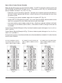
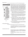
I
N
S
T
R
U
C
T
Q SERIES
REACH-IN
I
O
N
S
Q SERIES
REACH-IN
FOOD STORAGE CABINETS
701 S. RIDGE AVENUE
TROY, OHIO 45374-0001
937 332-3000
www.hobartcorp.com
FORM 14580 Rev. L (Jan. 2002)
Installation, Operation and Care of
Q SERIES REACH-IN FOOD STORAGE CABINETS
SAVE THESE INSTRUCTIONS
GENERAL
The Q Series Reach-In Food Storage Cabinets are available as low temperature (0°F), medium
temperature (38°F) refrigeration units or hot food storage cabinets (180°F maximum). They may be
ordered as one-, two-, or three-section cabinets.
A variety of optional cabinets is available. These include: Two- or three-section cabinets with a
combination of medium and low temperature sections or medium temperature and hot food storage
sections; two- or three section cabinets equipped with optional SAFE-T-THAW® equipment for safe,
rapid thawing at medium temperatures; convertible models which, by setting a selector switch, will
operate as either a low temperature or medium temperature unit; and single-section over/under
cabinets which feature a medium temperature and a low temperature unit, one on top of the other.
INSTALLATION
UNPACKING AND ASSEMBLY
Immediately after unpacking the reach-in, check for possible shipping damage. If this unit is found to
be damaged after unpacking, save the packaging material and contact the carrier within 15 days of
delivery.
Prior to installation, test the electrical service to assure that it agrees with the specifications on the
machine data plate located in the upper left corner inside the cabinet.
LOCATION
For optimum performance, the condensing unit of the reach-in (refrigeration models only) must have
an adequate supply of air for cooling purposes. The operating location must provide either a minimum
12" clearance overhead of the condensing unit or the unrestricted flow of air at the back of the reach-in.
–2–
MOUNTING SCREW
ASSEMBLY
ASSEMBLY
MOUNTING
SCREW
Some components can be removed to allow the cabinet
to pass through short or narrow doorways.
HANDLE ASSEMBLY
SCREW
The door handle can be removed as follows:
PLUG
BUTTON
BOLT
1. Remove the screw and bolt from the tumbler.
2. Remove the two mounting screws and the handle
assembly (Fig. 1)
DOOR
PL-50949
KEY
3. Replace in reverse order of disassembly.
Fig. 1
Door(s) and hinges can be removed as follows:
UPPER
HINGE
1. Lift up and remove the front trim
panel (Fig. 1).
FRONT TRIM PANEL
2. Remove the screws which secure
the trim rail cover (Fig. 1), unplug
the door switch lead wires, and
remove the screws which secure
the trim rail (Fig. 1). Carefully lay
the trim rail on top of the cabinet —
avoid damaging or kinking the
thermometer capillary tube.
3. Remove the three screws which
secure the upper hinge plate to the
cabinet (Fig. 2). This will remove
hinge tension. Remove the nut
underneath the lower hinge plate
which secures the bottom hinge.
Remove door. Remove lower hinge
plate (Fig. 2).
LOWER
HINGE
TRIM RAIL COVER
SCREWS
(3)
PL-53615
4. If the hinge mechanism should become
uncocked while changing the door, it will
be necessary to recock the hinge
mechanism. To do this, remove the door
from the cabinet and position the door
face down on a workbench or table. Using
a 5/16" open end or adjustable wrench, turn
the hinge mechanism shaft 135° (Fig. 3).
Fig. 2
Fig. 3
UNCOCKED POSITION
COCKED POSITION
TURN 135º
135º
– POSITION 1 – (LEFT-HAND HINGED DOOR)
UNCOCKED POSITION
5. Replace the hinge plates and door(s) in
the reverse order of disassembly.
If cabinets are too tall, the refrigeration system
may need to be removed in order to pass
through short openings. Contact your dealer or
authorized servicer if this becomes necessary.
PL-53617
TRIM RAIL
COCKED POSITION
TURN 135º
PL-50961
135º
– POSITION 2 – (RIGHT-HAND HINGED DOOR)
POSITION DOOR IN ONE OF THE TWO POSITIONS SHOWN.
Fig. 4
Once the cabinet is in its final position, replace any components that may have been removed (door
handle, etc.) and then level the cabinet front-to-back and side-to-side by adjusting the legs as required.
Door Hinging
Should the doors need to be rehinged (from right to left or vice versa), contact a Hobart-authorized
Refrigeration Service Company.
–3–
LEGS OR CASTERS
WARNING: THE CABINET MUST BE BLOCKED AND STABLE
BEFORE INSTALLING LEGS OR CASTERS.
THREADED HOLE
Legs (Fig. 5)
To install the legs, raise and block the reach-in a minimum of 7" from
the floor and thread the legs into the Threaded Holes on the bottom
of the cabinet. This unit must be level in order to operate properly.
Turn the adjustable feet in or out as required to level the unit
front-to-back and side-to-side.
RAISE
NOTE: Three-section front opening cabinets come with five legs,
the fifth leg should be placed in the front center threaded hole. In the
case of a three section pass through cabinet, a sixth leg is included
for the rear center hole. Failure to install these legs in the proper
location may result in damage to the cabinet.
LOWER
Fig. 5
PL-56125
Casters (Fig. 6)
Use casters only on reach-in models with self-contained refrigeration
systems that have cord and plug electrical connections. Raise and
block the cabinet a minimum of 7" from the floor. Thread the casters
into the holes in the bottom of the cabinet (Fig. 2). Casters with
brake should be installed at the front. Securely tighten the caster
with the octagon shaped Bolt head underneath — not the round
flange on top.
BOLT
PL-53353
Fig. 6
PILASTER
Shelves (Fig. 7)
If purchased, the shelves and shelf clips are shipped with the
cabinet. Insert the shelf clips into the pilaster and install the
shelves. Index holes are provided in the pilaster to help in
leveling the shelves.
COLD AIR
DUCT
Bonus shelves are provided to fill the space between the
shelves. These are positioned and supported by the shelves.
NOTE: Loosen all thumbscrews which secure shelf pilasters
and light cover(s) prior to placing product in cabinet.
Thumbscrews should be loose enough to remove with your
fingers so parts can be readily removed for cleaning without the
use of tools. Failure to comply with this request will invalidate
the NSF listing.
BONUS
SHELF
INDEX
HOLE
SHELF
CLIP
SHELF
PL-50910
Fig. 7
Utility Base (Optional)
If your unit comes with a utility base, we recommend securing the base to the floor to prevent damage
to the floor outlet due to accidental movement. The utility base is secured to the cabinet with four bolts,
one at each corner. The utility base is mounted at the factory. With the cabinet in its final installed and
leveled position, apply a bead of NSF approved sealant (not supplied) around the bottom. Access
covers, secured with screws, are provided on the left side and front for attaching the power supply cord
to a floor outlet underneath the cabinet.
Curb
The cabinet may be installed on a curb without legs or casters; the typical curb must be recessed a
minimum of 13/8" from the front of the cabinet (and rear if it is a pass through) to allow room for the hinges.
–4–
Compressor Mounts
Some Q Series units have the compressor specially mounted to help prevent damage during shipment.
If the compressor is mounted on shipping blocks, remove the shipping blocks before operating the
compressor. If the compressor is mounted on springs, refer to the tag attached to the compressor.
Condensate Evaporator
Q Series cabinets, except for remote or over/under units, are equipped with an automatic condensate
evaporator and require no drain connection.
ELECTRICAL CONNECTIONS (Cord Connected Reach-Ins) 120 Volt, 60 Hertz, 1 Phase
WARNING: THIS MACHINE IS PROVIDED WITH A THREE-PRONGED GROUNDING PLUG. THE
OUTLET TO WHICH THIS PLUG IS CONNECTED MUST BE PROPERLY GROUNDED. IF THE
RECEPTACLE IS NOT THE PROPER GROUNDING TYPE, CONTACT AN ELECTRICIAN.
ELECTRICAL CONNECTIONS (Permanently Connected Reach-Ins)
WARNING: ELECTRICAL AND GROUNDING CONNECTIONS MUST COMPLY WITH THE
APPLICABLE PORTIONS OF THE NATIONAL ELECTRICAL CODE AND/OR OTHER LOCAL
ELECTRICAL CODES.
WARNING: DISCONNECT ELECTRICAL POWER SUPPLY AND PLACE A TAG AT THE
DISCONNECT SWITCH INDICATING THAT YOU ARE WORKING ON THE CIRCUIT.
Make electrical connections per the wiring diagram supplied with the unit.
PRESTART CHECKS
REFRIGERANT LINES — Check for tubing shifts due to shipping that would cause operating noise,
wear or leaks.
SELECTOR SWITCH (Convertible Models Only) — The selector switch should be set to the proper
position. To gain access to the switch, remove the front trim panel (Fig. 2) by raising it up (to clear the
retaining slots) and out. Set the switch on the proper position (Refrigerator or Freezer) and replace the
trim panel.
OPERATIONAL CHECK — The refrigeration and defrost cycles should be checked for proper
operation and the thermometer(s) should also be checked for correct temperature indication — before
product is stored in the cabinet.
DEFROST TIMER — On freezer units, set the defrost timer as described in Operation.
OPERATION
CONTROLS (Refrigeration)
TEMPERATURE CONTROL — The temperature control is
set at the factory but local conditions may necessitate slight
adjustment. To adjust the temperature control, lift up and
remove the front trim panel (Fig. 2). Turn the control knob
(Fig. 8) a small amount at a time. Turning the control knob in
the direction of the arrow lowers the temperature. The control
knob has a marked OFF position which interrupts power to the
compressor and condenser fan only, not the entire reach-in.
TEMPERATURE
CONTROL
NOTE: Over/under units have separate temperature controls
for each refrigeration system. They are located on the front of
each evaporator housing.
PL-56151
Fig. 8
–5–
STANDARD THERMOMETER (Fig. 9) — The standard digital
thermometer is calibrated at the factory and does not permit
recalibration.
OPTIONAL DIAL THERMOMETER — The optional dial
thermometer can be recalibrated. Compare the cabinet
thermometer with an accurate test thermometer. If there is any
variation, contact a Hobart-authorized Refrigeration Service
Company.
Refr
igera
tor
PL-50767
Fig. 9
CONTROLS (Safe-T-Thaw Only)
The optional Safe-T-Thaw adaptation of the two- or three- section reach-in refrigerators significantly
reduces the defrost time of all frozen foods under a controlled environment without employing
temperatures over 45°F.
Safe-T-Thaw incorporates a two stage thermostat, a reversing valve on the refrigerant line, and multiple
fan units for increased internal air circulation. When non-frozen food is placed in the Safe-T-Thaw unit,
it operates as a normal refrigerator — the thermostat switches cooling on at 40°F and off at 36°F. When
a sufficient load of frozen food is placed in the cabinet to lower the temperature to 33°F, the heating mode
is activated. The two stage thermostat will switch the circulating fans on and reverse the refrigerant
valve so the warm refrigerant flows to the inside of the cabinet and the cool refrigerant goes to the
outside coil. When the cabinet has warmed to 40°F the thermostat turns off the warming. The cabinet
continues to cycle heat on at 36°F and off at 40°F.
When the frozen product has lost its ability to reduce the cabinet temperature to 36°F, heat from the fan
motors will gradually cause the cabinet temperature to climb to 45°F. At this point the thermostat will
reverse mode again to normal refrigeration cycle — cooling on at 40°F and off at 36°F.
Circulating fans do not work during normal refrigeration mode. All the apparatus works automatically
without adjusting the factory settings.
NOTE: To reduce the drying effect of the fans blowing air over foods, it is recommended that food
stored in the Safe-T-Thaw be covered.
CONTROLS (Hot Food Storage Units, Fig. 10)
The ON-OFF switch contains a pilot light which glows
whenever the switch is ON. Turn the switch OFF
whenever the cabinet is not in use. The ON-OFF
switch is not a disconnect switch — ALWAYS
DISCONNECT POWER AT THE SOURCE TO
SERVICE THE UNIT. The temperature control dial,
which has a marked OFF position (no heat), is used to
select the temperature at which the food will be held.
When this dial is OFF, the air circulating fans continue
to run.
The HUMIDITY control dial is used to regulate the
humidity level inside the cabinet. Three-section
cabinets have two HUMIDITY control dials.
–6–
Fig. 10
ELECTRONIC DEFROST TIMER (when equipped)
If your freezer is equipped with an electronic Defrost Timer, it is
located in a control box behind the trim rail at the top of the
Reach-In Freezer. To access the the Defrost Timer, remove the
Thumbscrew on the left side of the Control Box and slide the Lid
to the left (Fig. 11). Save the Thumbscrew and Lid and put them
back in place after programming is done.
THUMBSCREW
LID
CONTROL BOX
PL-41628-1
Fig. 11
The Defrost Timer's clock is operating from the backup power
supply (battery) during shipping and before installation. Once the
freezer is plugged in, the Defrost Timer operates off of the AC
power supply; the battery is only used during a power interruption
or outage. This battery is a permanent type that is not replaceable
except by replacement of the defrost timer itself. For additional
information on behavior of the defrost timer if the battery loses
power, refer to page 11. When the AC power is plugged in, the
defrost time clock automatically switches the battery to a standby
condition.
When the Freezer is connected to the AC electrical power supply,
the SET CLOCK light on the Defrost Timer (Fig. 12) blinks rapidly
to indicate that the Defrost Timer is in normal Operation Mode.
The Defrost Time Clock is set at the factory to the current timeof-day for Central Standard Time. The Defrost Duration is preset
at the factory to run for 25 minutes. Also, the Defrost Schedule is
preset at the factory to start a defrost cycle four times each day,
at 2 AM, 8 AM, 2 PM and 8 PM. The factory preset defrost schedule
is active during normal Operation Mode if all 24 switches are OFF.
Switches are OFF when tabs are positioned to the left (Fig. 12).
Fig. 12
The backup power supply (battery) maintains the correct time-ofday during shipping. If the freezer stays in the Central Time Zone,
the time-of-day does not need to be reset. If the freezer is installed
in a different time zone, the time clock can be reset to the correct
time-of-day if desired. Refer to Setting the Time Clock to the
Current Time-of-Day (page 8).
PROGRAMMING THE ELECTRONIC DEFROST TIMER
Use a small probe such as a pen, pencil or screwdriver to move the switches during programming.
Switches are OFF when the tab is left, ON when tab is moved to the right.
Before programming, if the initial switch settings are not all off (Fig. 12), make a record of the current
switch settings on a piece of paper; this indicates the current defrost schedule. Then slide all 24
switches to the left or OFF position (Fig. 12).
During programming, all settings must be completed within 4 minutes or the timer will return to normal
Operation Mode. Once programming is done, restore the previous defrost schedule by returning the
switches to the same positions noted on your record.
–7–
To Change the Defrost Duration and Bypass the Setting of the Time Clock
Begin with the SET CLOCK light blinking rapidly, indicating normal Operation Mode . . .
If you want to change the Defrost Duration but not reset the time-of-day, press and hold the PROGRAM
button for about 3 seconds until the PROGRAM light starts blinking. Release the PROGRAM button
and the PROGRAM light and the SET CLOCK light remain lit. Press and hold the PROGRAM button
again until the DEFROST ON light starts blinking. Release the PROGRAM button and the DEFROST
ON light remains lit. Skip the section titled Setting the Time Clock to the Current Time-of-Day (below)
and continue with Setting the Defrost Duration (bottom of this page).
Setting the Time Clock to the Current Time-of-Day
Begin with the SET CLOCK light blinking rapidly, indicating normal
Operation Mode . . .
• Begin with all switches OFF (Fig. 12).
• Press and hold the PROGRAM button for about 3 seconds until the
PROGRAM light starts blinking. Release the PROGRAM button and
the PROGRAM and the SET CLOCK lights remain lit.
• The upper set of switches sets the HOUR. Slide the switch that
corresponds to the current hour to the right. The 11 other switches
remain OFF.
• The lower set of switches sets the MINUTES. Find the switch that
is within 5 minutes of the current minutes and move it to the right. At
least 10 of the other switches in the lower set remain OFF. If the time
is 0 to 3 minutes after the hour, all 11 switches can remain OFF.
• The last switch of the lower set of switches selects AM or PM. Leave
the tab on the left for AM. Slide the tab to the right for PM.
Fig. 13
The example, Fig. 13, sets the Time Clock at 2:45 PM.
Press and hold the SET button until the SET CLOCK light starts blinking. Release the SET button; the
SET CLOCK light goes off and the DEFROST ON light begins to blink and then remains on. Continue
with Setting the Defrost Duration. To exit without setting the Defrost Duration, return all switches to the
left, press the PROGRAM button for three seconds and release the PROGRAM button — normal
Operation Mode returns with the SET CLOCK light blinking rapidly.
Setting the Defrost Duration
The Defrost Duration was preset at the factory for 25 minutes. Depending
on freezer usage and your defrost schedule, you may choose to customize
the Defrost Duration. The usual and recommended Defrost Duration
setting is 25 minutes.
Complete either the section titled To Change the Defrost Duration and
Bypass the Setting of the Time Clock or complete the section titled Setting
the Time Clock to the Current Time-of-Day before continuing.
With the PROGRAM and the DEFROST ON lights lit . . .
• Move all 24 switches to the left or OFF position.
• In the lower set of switches, move the one switch to the right that
corresponds to the desired Defrost Duration (nearest 5 minutes).
The example, Fig. 14, sets the Defrost Duration at 30 minutes.
Press and hold the SET button until the DEFROST ON light starts
blinking. Release the SET button and the SET CLOCK light flashes
rapidly indicating that the timer has returned to normal Operation Mode.
To verify that the clock and the defrost duration are set properly, perform
Program Review (page 10).
–8–
Fig. 14
How to Set a Custom Defrost Schedule
Begin with the defrost timer on normal Operation Mode: The SET CLOCK light is blinking rapidly and
the PROGRAM and DEFROST ON lights are off. If all switches are OFF (Fig. 15), the factory preset
defrost schedule is enabled: 2 AM, 8 AM, 2 PM, 8 PM.
• Determine your own best defrost schedule. The upper set of switches represents the AM hours;
the lower switches represent the PM hours. Allow a minimum of 2 hours between the start of any
two defrost cycles.
• To customize your defrost schedule, begin with all switches OFF (Fig. 15).
• With the SET CLOCK light blinking rapidly, as in normal Operation Mode, slide the switches to the
right that correspond to the hour when each defrost cycle should begin.
• If you want a defrost cycle to begin on the half-hour, slide the two adjacent switches to the right.
For example, to start a defrost cycle at 2:30 PM, Slide switches 2 and 3 to the right in the lower set
of switches.
Custom Defrost Schedule Example #1 (Fig. 16) shows five defrost cycles that begin at 1 AM , 6 AM, 10
2:30 PM and 8 PM.
AM ,
Custom Defrost Schedule Example #2 (Fig. 17) shows six defrost cycles that begin at 1 AM, 4 AM, 10
2:30 PM, 6 PM and 9:30 PM.
AM ,
During normal operation, leave these switches set on the desired defrost schedule if it is other than the
factory preset schedule.
ALL SWITCHES OFF GIVES YOU THE
FACTORY PRESET DEFROST SCHEDULE:
2:00 AM, 8:00 AM, 2:00 PM, 8:00 PM
Fig. 15
CUSTOM D EFROST SCHEDULE EXAMPLE #1:
1:00 AM, 6:00 AM, 10:00 AM, 2:30 PM,
8:00 PM
CUSTOM DEFROST SCHEDULE EXAMPLE #2:
1:00 AM, 4:00 AM, 10:00 AM, 2:30 PM,
6:00 PM, 9:30 PM
Fig. 16
Fig. 17
–9–
Program Review
During normal Operation Mode, with the SET CLOCK light blinking rapidly . . .
Current Clock Time = HH:MM
# Blinks = HH
# Blinks (times 5) = MM
Press the SET button until the SET CLOCK, PROGRAM, and
DEFROST ON lights are lit; then release the SET button and all
three lights go off for two seconds. After that, all three lights begin
to blink. The number of blinks of a light corresponds to the
programmed value for that light. A three second pause follows the
last blink before the cycle repeats. The Review Mode's sequence
of blinking lights (Fig. 18) repeats ten times to give you plenty of
chances to count the number of blinks for each light. Review Mode
can be stopped at any time by pressing the SET button for 3
seconds; when the SET button is released, normal Operation
Mode returns with the SET CLOCK light blinking rapidly.
The SET CLOCK light blinks from 1 to 12 times to indicate the
TIME CLOCK HOUR. If the final blink for the hour count
remains on for two seconds, it indicates PM; if the final blink
for the hour count is a normal blink, it indicates AM.
While the SET CLOCK light is blinking the HOUR, the PROGRAM
light blinks from 0 to 11 times to indicate the TIME CLOCK
MINUTES to the nearest 5 minutes after the hour: 0 blinks =
0 minutes, 1 blink = 5 minutes, 2 blinks = 10 minutes, . . .
11 blinks = 55 minutes.
# Blinks (times 5) =
DEFROST DURATION
Fig. 18
While the SET CLOCK light is blinking the HOUR and the
PROGRAM light is blinking the MINUTES, the DEFROST ON
light blinks from 0 to 11 times to indicate the DEFROST
DURATION setting to the nearest 5 minutes: 0 blinks = 0
minutes, 1 blink = 5 minutes, 2 blinks = 10 minutes, . . .
11 blinks = 55 minutes.
After the ten blinking sequences are done or after Review Mode
has been stopped, normal Operation Mode returns with the
SET CLOCK light blinking rapidly.
Initiating a Manual Defrost
During normal Operation Mode, with the SET CLOCK light blinking rapidly . . .
Press the MANUAL DEFROST button for about 3 seconds until
the DEFROST ON light comes on. The Defrost Cycle is started
and continues for the amount of time programmed for DEFROST
DURATION (page 8).
Cancelling a Defrost Cycle
While a Defrost Cycle is in progress, the DEFROST ON light is lit.
A Defrost Cycle that is in progress can be terminated by pressing
the MANUAL DEFROST button for 3 seconds. The DEFROST
ON light goes off.
The normal DEFROST SCHEDULE continues to operate as
programmed.
– 10 –
If the Defrost Timer's Battery Loses Power
If the SET CLOCK, PROGRAM and DEFROST ON lights are all blinking, the backup power supply
(battery) to the Defrost Timer has weakened. Estimated battery life is 10 years. The timer can
continue to function normally after the battery has weakened if the timer is reprogrammed.
If a power outage occurs and is later restored after the battery has weakened, the following three
things happen:
• The defrost clock resumes as if it were 12:00 midnight.
• The position of the switches dictates the defrost schedule. If all switches are OFF, the factory
preset times of 2 AM , 8 AM, 2 PM and 8 PM will initiate deftost cycles 2, 8, 14 and 20 hours after
power was restored.
• The factory preset defrost duration of 25 minutes is re-invoked.
Because the clock resumed at 12:00 midnight, it must be reset to the current time-of-day to avoid
inconvenient defrost cycles. Refer to Setting the Time Clock to the Current Time-of-Day (page 8).
If the Defrost Duration was set at a value other than the factory preset 25 minutes, reset it. If power
is lost again, reset again. Refer to Setting the Defrost Duration (page 8).
If you are using a custom Defrost Schedule, the switches must be reset after resetting the time and
Defrost Duration. Any defrost start times that are set by the positions of the program switches will
override the factory preset defrost start times even if the battery is weakened.
If the battery has weakened and reprogramming the time-of-day, defrost duration and schedule after
a power interruption is too inconvenient, the Electronic Defrost Timer can be replaced.
In the event of a power surge or lightning, the SET CLOCK, PROGRAM and DEFROST ON lights will
all blink the same as for a weak battery but the battery may not have weakened. First, try to reprogram
the Defrost Timer. If the Defrost Timer fails to function normally, contact service.
MECHANICAL DEFROST TIMER (Fig. 19)
When equipped on Freezers or on Convertible Models with Freezer Chambers, when power is initially
applied to the cabinet, the exterior dial of the defrost time clock must be set to the correct time of day.
To access the defrost timer, remove the front
trim panel (Fig. 2) by lifting up and out. Open
door on the defrost timer box. Turn the inside
knob counterclockwise until the exterior dial is
positioned so the correct time of day is at the
time of day pointer. Replace the front trim
panel when done.
TIME-OF-DAY POINTER
EXTERIOR DIAL (24 HOUR)
TURN KNOB
COUNTERCLOCKWISE
DEFROST CYCLE PINS
The defrost timer (Fig. 19) is set at the factory
for four 26-minute defrost cycles per day (2 AM,
8 AM, 2 PM and 8 PM). Depending on local
conditions, it may be necessary to change the
frequency or duration of defrost cycles.
If the power supply is interrupted, the defrost
timer must be reset to the correct time of day.
END DEFROST
(26 MINUTES)
BEGIN DEFROST
PL-41397-1
Fig. 19
– 11 –
MAINTENANCE
CLEANING
Cabinet
Clean the inside of the cabinet and the doors weekly with a warm water solution of mild household liquid
dishwashing detergent (such as Palmolive green or Ivory). Do not use anything containing grit,
abrasive materials, bleach or harsh chemicals. Be cautious with new or improved formulas; use only
after being well tested. Rinse thoroughly and dry with a clean soft cloth.
Gaskets
Door gaskets should be cleaned weekly using a warm water solution of mild household liquid
dishwashing detergent (such as Palmolive green or Ivory). Never allow gaskets to contact concentrated
cleaners or disinfectants. This can cause premature failure of the gasket material.
Condenser Coil
WARNING: DISCONNECT ELECTRICAL POWER SUPPLY BEFORE CLEANING THE CONDENSING
UNIT.
Check the condenser coil weekly. This surface must be kept free of dirt and grease for proper system
operation. Remove the front trim panel and carefully vacuum or brush dirt and lint from the condenser
coil. Replace the trim panel.
Evaporator Coil, Drain Pan, Condensate Loop and Condensate Dish
When needed, flush these components with fresh water. This should be a part of any routine
maintenance program and can prolong the life of the equipment.
Light Bulb Replacement (when equipped)
Replace light bulb(s) with 40 watt incandescent appliance type bulb(s) ONLY. The protective cover
can easily be removed and replaced.
Florescent Light Bulb Replacement (when equipped)
Remove protective cover. Replace florescent tube with same size and type: 40 watt, 48" long.
TROUBLESHOOTING
SYMPTOM
POSSIBLE CAUSE
Unit fails to operate.
Power failure.
Plug loose in receptacle.
Blown fuse or tripped circuit breaker.
If a freezer model is in a deftost cycle, wait 30 minutes and recheck.
Check the Temperature Control (page 5 or 6) to make sure it is not OFF.
If the suggestions above fail to remedy the situation, contact service.
WARRANTY
The Q series cabinet warranty is for two years. It includes parts, labor and travel during normal working
hours in the continental United States. The non-prorated compressor warranty is for an additional three
years and does not include labor.
For additional information or to discuss a maintenance program, contact your local authorized
refrigeration servicer.
FORM 14580 Rev. L (Jan. 2002)
– 12 –
PRINTED IN U.S.A.