1
For More Precise Control
For General Purpose Use
Hitachi Industrial Equipment Systems Co., Ltd.
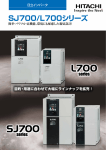
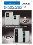
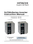
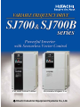
SJ700
Series
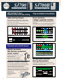
Line up
For More Precise Control
SJ700B
For General Purpose Use
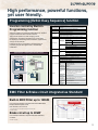
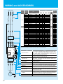
High starting Torque,
Powerful Drive and easy setting
Trip avoidance function
High starting Torque
Over current &
voltage suppress function
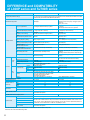
Improved Sensorless Vector Control and Auto Tuning
produce high starting torque of 200% or more at 0.3Hz.*1
Easy setup of motor constants
Ideal for applications which need high torque, such as
cranes, extruders and lifts.
Higher internal calculation speed improves current control
performance.
Over-current suppress and Over-voltage suppress functions
avoid inverter trip during acceleration and deceleration.
Motor Torque vs. Speed
Frequency
Torque [%]
200
0.3Hz
100
OC-Trip
0
300
-100
600
900
1200
1500
1800
Motor current
-200
Speed (min-1)
*1 Starting torque
Series
SJ700
SJ700B
Applicable motor
0.4 to 55kW
75 to 132kW
185 to 400kW
11 to 75kW
90 to 160kW
Starting torque
0.3Hz/200%
0.3Hz/180%
0.3Hz/150%
0.5Hz/150%
0.5Hz/120%
Possible with SJ700 Series
Hitachi exclusive
0Hz Domain sensorless
vector control *)
Develops 150%(SJ700B:120%) *2 torque at
0Hz speed reference
Ideal for cranes and other applications
that require high torque at starting.
*2 when inverter is one frame size larger than motor.
Position Control Function *)
The SJ700, with optional feedback board installed, together
with an encoder-equipped motor can perform position control.
For many applications, suitable performance can be
achieved at a lower cost than servo systems.
Based on your four motion parameters (position command,
speed command, acceleration time and deceleration time),
the SJ700 will move an object from original position A to
target position B.
Starting point A
After the movement,
Target point B
the inverter keeps servo
lock status.
1
*) Derating is applied for SJ700B. Please consult technician at Hitachi or its distributor before use.
Over-current suppress OFF
Impact load
Suppresses over current and continues running
Over-current suppress ON
DC Bus AVR Function
During Deceleration
The SJ700 controls deceleration time so that the DC bus
voltage does not exceed the over-voltage trip level, providing
trip-less operation during deceleration.
Motor current
Voltage of the
main circuit DC
Output frequency
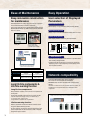
High performance, powerful functions,
yet user friendly.
Programming [EzSQ: Easy Sequence] function
Inverter control by Built-in
Programming function
Item
Language Spec
Language type
I/O function
Sequence operation is realized by downloading to an inverter a
program created with Hitachi's EzSQ software.
Tailor inverter operation to meet changing process
requirements, and replace separate PLCs in some cases.
By simplifying or eliminating external hardware, signficant cost
savings can be achieved.
Password function is incorporated to provide security for
proprietary program data against loss or unauthorized
modification.
PB1
PB2
T2
Memory area
SJ700 Using EzSQ
Program download/upload, All clear
Executable format Interpreter 2.0ms/command (Sub routine supported. 8 nested)
Contact signal/Open collector signal input
(Internal DC24V power supply available)
External digital Program RUN
FW terminal is reserved
command
contact input
General-purpose
External input
Maximum of 8 point(X(00)-X(07))
input
XA(0) : 0-10V (O terminal)
External analog
XA(1) : 4-20mA (OI terminal)
input
XA(2) : 0-10V (O2 terminal)
General-purpose
Maximum of 8 point(Y(00)-Y(05))
output terminal
Command
RY2
T2
Programming Window
Download
PB1
RYA
FW
RYB
8
CM1
YA(2) : Setup for AMI terminal is possible.
PB2
User
U(00)-U(31)/32 point
Set frequency
SET-Freq
Timer
EzSQ
Programming
RYB
RY2
Operation
circuit
YA(1) : Setup for AM terminal is possible.
Timer control <on delay, off delay>
Inverter parameter setting
Reserved word
T1
YA(0) : Setup for FM terminal is possible.
I/O control(Bit input, Word input, Bit output, Word output)
RY1
PB1
External analog
output
Programmable flow control <Loop, Unconditional jump, conditional jump,
Time control, Sub routine, Others>
Operation command <+,-,,*, /, substitution, mod, abs>
T1
PB2
Windows(DOS/V)OS:Windows2000, WindowsXP)
1,024 steps or 6k byte
(Smaller of these)Program is stored in internal of inverter.
Grammar check(Windows)
RYA
RY1
Description
Editor(Windows), Display(Windows)
Programming
environment
External output
Typical Example - Replacing External Relay Circuit
Standard Inverter
Supported Device
BASIC Like
1
Variable
Acceleration time
Deceleration time
ACCEL
DECEL
Monitor
Output frequency, Output current, Rotative direction,
PID feedback, Converted frequency, Output torque,
Output voltage, Power, Cumulative RUN time,
Cumulative power-on time, trip
General-purpose
input contact
General-purpose
output contact
2
CM1
Internal user
Internal timer
contact
Inverter input
and output
*
UL(00)-UL(07)/8 point
X(00)-X(07)/8 point
Y(00)-Y(05)/6 point(1 point is relay output)
UB(00)-UB(07)/8 point
TD(0)-TD(7)/8 point
In a remote operator display code.
Windows® is a registered trademark of Microsoft Corporation.U.S.A and other countries.
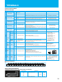
EMC Filter & Brake circuit integrated as Standard
Example (SJ700-110HFEF2)
Built-in EMC Filter up to 150kW
*
Meets EN61800-3 2nd-Environment
*
SJ700: European Version and Japanese Version does not have 150 kW
SJ700B: All models
Brake circuit up to 22kW*
Cost and Space reduction compared with external Braking
Controller.
*
SJ700B: Up to 30kW
120
EN61800-3 2nd Envinment
[C3]QP Limit Level
110
100
Level [db]
Cost and space reduction compared with external EMC Filter.
Reduces electromagnetic noise.
130
90
80
70
60
50
40
30
20
10
0
150k200k
500k
1M
2M
Frequency [Hz]
5M 7M 10M
20M 30M
QP: Quasi Peak
2
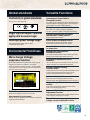
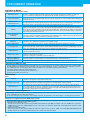
Ease of Maintenance
Easy Operation
Easy-removable construction
for maintenance
User selection of Displayed
Parameters
Field replacement of cooling fan(s) and DC bus capacitors
can be accomplished in a fraction of the time.
Using Logic terminal move to SJ700 without wiring change.
Read SJ300 Parameter by SRW remote operator and write
them in to SJ700
Data comparison function
Allows display of only parameters changed from default.
User selected function
Display of up to 12 User Defined Parameters U001 to U012.
Basic mode (default)
Basic display mode for commonly used parameters.
Easy-removable
Cooling Fan
Easy-removable
DC bus Capacitors
(SJ700: above 15kW
SJ700B: above 18.5kW)
SJ300series
SJ700series
Parameter
read write
Basic
mode
Chose Basic
Parameter
Indication only
Basic Parameter
Other Functions
Removable Control circuit terminals
(Move to SJ700 without rewiring)
*1 Control circuit terminals comparison table
Series
SJ700
SJ700B
SJ300
L300P
Input terminals
Output terminals
9terminals
5terminals
(Intelligent 8terminals,FW) (Open collector outputs)
6terminals
(Intelligent 5terminals,FW)
2terminals
(Relay outputs)
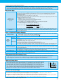
Long life time components &
Life time warning function
Long life time components
Design lifetime 10 Years or more for DC bus capacitors &
Cooling Fan.
Cooling Fan ON/OFF control function for longer fan life.
*Ambient temperature: Average 40 deg C (SJ700B: 30 deg C)
(no corrosive gases, oil mist or dust)
Design lifetime is calculated, and not guaranteed.
Life time warning function
Perform preventive maintenance before a failure occurs
using the Lifetime Warning function.
DC bus capacitor, cooling fan, heat sink temperature and
motor temperature can be monitored in order to replace
components prior to failure.
3
-The direct input of function code selection is possible rather
than scrolling through the list.
-Holding down the function key for 3 seconds, causes the
display to jump to output frequency monitor (d001) mode
from any menu location.
Network compatibility
A serial RS-485 Modbus-RTU port is standard.
The SJ700 can communicate with DeviceNet,
PROFIBUS-DP, and other networks with communication
options.
-DeviceNet is a trade mark of Open DeviceNet Vender Association, Inc.
-PROFIBUS-DP is a registered trade mark of PROFIBUS Nutzer
Organization
Simple & Low cost wiring, Ease of installation and replacement
Global standards
Versatile Functions
Conformity to global standards
Instantaneous Power Failure
Disregard Function
CE, UL, c-UL, C-Tick approvals.
The SJ700 ignores instantaneous power failure when power
fluctuation happens frequently, as long as DC bus voltage
remains higher than under-voltage trip level.
Emergency stop
Logic input & output Terminal
apply sink & source logic
Wide Input power voltage range
Input voltage 240V for 200V class and 480V
for 400V class as standard.
Environmental Friendliness
Micro Surge Voltage
suppress function
Hitachi original PWM control method limits motor terminal
voltage to less than two of inverter DC bus voltage.
Lower than Hitachi motor Max. insulation voltage (1,250V)
(During regeneration, the motor terminal voltage may exceed the motor
maximum insulation voltage (1,250V))
Motor terminal voltage
Shuts down the inverter by hardware, bypassing
the CPU, to achieve a reliable, emergency stop function.
Intelligent input terminal and output
terminal ON/OFF delay function
Helps simplify external circuits.
Active frequency matching function
Motor frequency match restart function operates
effectively even without motor residual voltage.
Controlled deceleration and stop
on power loss
Analog Input Disconnection
Detection Function
The SJ700 (SJ700B) outputs a disconnection signal when
frequency command through analog input is lost.
Acceleration/ Deceleration curve
functions
The curve shape (five kinds, such as S-curve, etc.) can be
chosen according to the application requirements.
Analog Command Holding
Function (AHD)
Output frequency can be changed with UP/DOWN Function,
or with an analog signal as reference value. The set
frequency at power shutdown can be saved, too.
Pulse train input function
1,250V
E=650V, cable=100m
EU RoHS compliant
EU RoHS compliant (except solder in power module)
Improvement of environment
Varnish coating of internal PC board & plating of main circuit
copper bus bar are standard.
Pulse train input for Frequency reference or PID
feed back signal, with SJ-FB (speed feed back card option).
Integrated Input Electric Power
monitor
Input electric power (kW) and Integrated input electric
power for monitoring energy saving.
Automatic Carrier Frequency
Adjustment Function
The SJ700 detects motor current and automatically reduces
carrier frequency according to the current.
The resolution of analog outputs
(voltage, current) is improved to 10 bits.
4
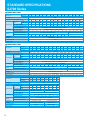
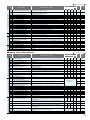
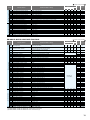
STANDARD SPECIFICATIONS
SJ700 Series
3-phase 200V class
Model SJ700-
JP Version
004LFF2 007LFF2 015LFF2 022LFF2 037LFF2 055LFF2 075LFF2 110LFF2 150LFF2 185LFF2 220LFF2 300LFF2 370LFF2 450LFF2 550LFF2
US Version
004LFUF2 007LFUF2 015LFUF2 022LFUF2 037LFUF2 055LFUF2 075LFUF2 110LFUF2 150LFUF2 185LFUF2 220LFUF2 300LFUF2 370LFUF2 450LFUF2 550LFUF2
Enclosure (*1)
IP20
Applicable motor (4-pole, kW(HP)) (*2)
Rated capacity
(kVA)
Output Ratings
0.4(1/2) 0.75(1)
30(40)
37(50)
45(60)
55(75)
200V
1.0
1.7
2.6
3.6
5.7
8.3
11.0
15.9
22.1
26.3
32.9
41.9
50.2
63.0
76.2
240V
1.2
2.0
3.1
4.3
6.8
9.9
13.3
19.1
26.6
31.5
39.4
50.3
60.2
75.6
91.4
3
5
7.5
10.5
16.5
24
32
46
64
76
95
121
145
182
220
133
160
200
242
Rated output current (A)
1.5(2)
2.2(3)
3.7(5)
5.5(7.5) 7.5(10) 11(15)
Overload capacity(output current)
150%,60sec., 200%,3sec.
Rated output voltage (*3)
Input Rating
Braking
3-phase (3-wire) 200 to 240V (corresponding to input voltage)
Rated input voltage (V)
Rated input current (A)
3-phase 200 to 240V+10%, -15%, 50/60Hz±5%
3.3
5.5
8.3
12
Dynamic braking (Short-time) (*4)
Minimum value of resistor (Ω)
18
26
35
51
50
50
35
35
35
16
10
7.5
2.9m/s2(0.3G), 10-55Hz
Built-in
JP Version
Model SJ700-
US Version
007HFF2 015HFF2 022HFF2 037HFF2 055HFF2 075HFF2 110HFF2 150HFF2 185HFF2 220HFF2 300HFF2 370HFF2 450HFF2 550HFF2
007HFUF2 015HFUF2 022HFUF2 040HFUF2 055HFUF2 075HFUF2 110HFUF2 150HFUF2 185HFUF2 220HFUF2 300HFUF2 370HFUF2 450HFUF2 550HFUF2
Rated capacity
(kVA)
IP20
0.75(1)
1.5(2)
2.2(3)
3.7(5)
4.0(5)
30(40)
37(50)
45(60)
55(75)
400V
1.7
2.6
3.6
6.2
9.7
13.1
17.3
22.1
26.3
33.2
40.1
51.9
63.0
77.6
480V
2.0
3.1
4.4
7.4
11.6
15.8
20.7
26.6
31.5
39.9
48.2
62.3
75.6
93.1
2.5
3.8
5.3
9.0
14
19
25
32
38
48
58
75
91
112
64
83
100
123
Applicable motor (4-pole, kW(HP)) (*2)
Rated output current (A)
5.5(7.5) 7.5(10)
Overload capacity(output current)
3-phase 380 to 480V +10%, -15%, 50/60Hz±5%
2.8
4.2
9.9
5.8
Dynamic braking (Short-time) (*4)
Minimum value of resistor (Ω)
15(20) 18.5(25) 22(30)
3-phase (3-wire) 380 to 480V (corresponding to input voltage)
Rated input voltage (V)
Rated input current (A)
11(15)
150%,60sec., 200%,3sec.
Rated output voltage (*3)
17
23
30
35
100
100
70
100
70
35
35
24
6(13.2)
6(13.2) 14(30.8) 14(30.8) 14(30.8) 22(48.4) 30(66)
US Version
750HFUF2 900HFUF2 1100HFUF2 1500HFUF2 1850HFU2 2200HFU2 3150HFU2 4000HFU2
JP Version
750HFF2 900HFF2 1100HFF2 1320HFF2 1850HF2
Applicable motor (4-pole, kW(HP)) (*2)
4000HF2
75(100) 90(125) 110(150) 132(175) 185(250) 220(300) 315(400) 400(550)
103.2
121.9
150.3
180.1
256
305
416
554
480V
123.8
146.3
180.4
216.1
308
366
499
665
149
176
217
260
370
440
600
800
Overload capacity(output current)
3-phase (3-wire) 380 to 480V (corresponding to input voltage)
Rated input voltage (V)
Rated input current (A)
Dynamic braking (Short-time) (*4)
150%,60sec., 180%,0.5sec.
150%,60sec., 200%,0.5sec.
Rated output voltage (*3)
5
3150HF2
400V
Rated output current (A)
3-phase 380 to 480V +10%, -15%, 50/60Hz±5%
164
194
239
286
389
455
630
840
External dynamic braking unit (option)
-
Minimum value of resistor (Ω)
Zero-phase Reactor
2200HF2
IP00
Enclosure (*1)
EMC filter
-
Built-in
3.5(7.7) 3.5(7.7) 3.5(7.7) 3.5(7.7) 6(13.2)
Rated capacity
(kVA)
20
2.9m/s2(0.3G), 10-55Hz
European Version 750HFEF2 900HFEF2 1100HFEF2 1320HFEF2 1850HFE2 2200HFE2 3150HFE2 4000HFE2
Weight [kg] (lbs.)
24
Built-in (EN61800-3 category C3)
Weight [kg] (lbs.)
Model SJ700-
53
External dynamic braking unit (option)
5.9m/s2(0.6G), 10-55Hz
Zero-phase Reactor
Vibration (*5)
42
Built-in BRD circuit (optional resistor)
EMC filter
Braking
30(66) 43(94.6)
European Version 007HFEF2 015HFEF2 022HFEF2 040HFEF2 055HFEF2 075HFEF2 110HFEF2 150HFEF2 185HFEF2 220HFEF2 300HFEF2 370HFEF2 450HFEF2 550HFEF2
Enclosure (*1)
Input Rating
-
5
3.5(7.7) 3.5(7.7) 3.5(7.7) 3.5(7.7) 3.5(7.7) 6(13.2) 6(13.2) 6(13.2) 14(30.8) 14(30.8) 14(30.8) 22(48.4) 30(66)
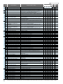
3-phase 400V class
Output Ratings
7.5
Built-in (EN61800-3 category C3)
Weight [kg] (lbs.)
Vibration (*5)
105
External dynamic braking unit (option)
10
Zero-phase Reactor
Braking
84
5.9m/s2(0.6G), 10-55Hz
EMC filter
Input Rating
70
Built-in BRD circuit (optional resistor)
Vibration (*5)
Output Ratings
15(20) 18.5(25) 22(30)
2.9m/s2(0.3G), 10-55Hz
1.96m/s2(0.2G), 10-55Hz
Built-in (EN61800-3 category C3)
External Option
Built-in
External Option
60(132) 60(132) 80(176) 80(176) 140(308) 145(319) 210(462) 360(792)
30(66)
30(66)
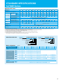
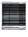
STANDARD SPECIFICATIONS
SJ700B Series
3-phase 400V class
Model SJ700B-
110HFF
150HFF
185HFF
220HFF
300HFF
Enclosure (*1)
Applicable motor (4-pole, kW(HP)) (*2)
Rated capacity
(kVA)
Output Ratings
550HFF
750HFF
900HFF 1100HFF 1320HFF 1600HFF
75(100)
90(125) 110(150) 132(150) 160(220)
IP00
15(20)
22(30)
30(40)
37(50)
400V
18.5(25)
45(60)
55(75)
15.2
20.0
25.6
29.7
39.4
48.4
58.8
72.7
93.5
110.8
135.1
159.3
200.9
480V
18.2
24.1
30.7
35.7
47.3
58.1
70.6
87.2
112.2
133
162.1
191.2
241.1
22
29
37
43
57
70
85
105
135
160
195
230
290
199
253
300
70(154)
70(154)
Rated output current (A)
120%,60sec
Rated output voltage (*3)
3-phase (3-wire) 380 to 480V (corresponding to input voltage)
Rated input voltage (V)
3-phase 380 to 480V +10%, -15%, 50/60Hz±5%
Rated input current (A)
24
Dynamic braking (Short-time) (*4)
Braking
450HFF
11(15)
Overload capacity(output current)
Input Rating
370HFF
IP20
32
41
63
47
77
94
116
Built-in BRD circuit (optional resistor)
Minimum value of resistor (Ω)
35
35
24
176
-
20
24
5.9m/s2(0.6G), 10-55Hz
Vibration (*5)
149
External dynamic braking unit (option)
2.9m/s2(0.3G), 10-55Hz
EMC filter
Built-in (EN61800-3 category C3)
Zero-phase Reactor
Built-in
6(13.2)
Weight (lbs.)
6(13.2)
14(30.8) 14(30.8) 14(30.8) 22(48.4)
30(66)
30(66)
30(66)
55(121)
55(121)
*1: The protection method conforms to JEM 1030.
*2: The applicable motor refers to Hitachi standard 3-phase motor (4-pole).To use other motors, be sure to prevent the rated motor current (50Hz) from exceeding the rated output current of the inverter.
*3: The output voltage decreases as the main power supply voltage decreases except for the use of AVR function.
*4: Braking resistor is not integrated in the inverter. Please install optional braking resistor or dynamic braking unit when large braking torque is required.
*5: Conforms to the test method specified in JIS C 60068-2-6 : 2010 (IEC 60068-2-6 : 2007).
*6: To operate the motor beyond 50/60Hz, please consult with the motor manufacturer about the maximum allowable rotation speed.
*7: Storage temperature refers to the temperature in transportation.
*8: The frequency command is the maximum frequency at 9.8V for input voltage 0 to 10VDC, or at 19.6mA for input current 4 to 20mA.
If this characteristic is not satisfactory for your application,contact your Hitachi representative.
Model Name Indication
SJ700 - 055 H F E F 2
SJ700 series
Series Name
Applicable Motor Capacity
SJ700B series
Series Name
Applicable Motor Capacity
004: 0.4kW(1/2HP)
|
4000:400kW(500HP)
Power Source L: 3-phase 200V class
H: 3-phase 400V class
F: With keypad
U : US version
E : European version
Note: Japanese version
F: Integrated EMC filter
Version
Model Configuration
Applicable Motor kW (HP)
Power Source
SJ700 B- 110 H F F
110: 11kW(15HP)
|
1600:160kW(220HP)
H: 3-phase 400V class
F: With keypad
F: Integrated EMC filter
Available
0.4
(1/2)
0.75
(1)
1.5
(2)
2.2
(3)
3.7
(5)
4.0
(5)
5.5
7.5
(7.5) (7.5)
11
(15)
15
(20)
18.5
(25)
22
(30)
30
(40)
37
(50)
45
(60)
55
(75)
75
90
110
132
150
160
185
220
315
400
(100) (125) (150) (175) (200) (220) (250) (300) (400) (550)
SJ700
3-phase 200V
LFUF2
LFF2
HFEF2
3-phase 400V
HFUF2
HFF2
SJ700B
3-phase 400V
HFF
6
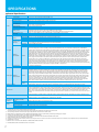
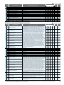
SPECIFICATIONS
General Specifications
General Specifications
Items
Control method
Line to line sine wave pulse-width modulation (PWM) control
Frequency accuracy
Frequency resolution
Digital: ±0.01% of the maximum frequency, Analog: ±0.2%(25±10˚C)
Digital setting: 0.01Hz, Analog setting: (Maximum frequency)/4,000 (O terminal: 12bit 0-10V, O2 terminal: 12bit -10-+10V)
Output frequency range (*6)
V/f optionally variable (30-400Hz of base frequency), V/f control (constant torque, reduced torque), Sensorless vector control, 0Hz domain sensorless vector
control, vector control (SJ-FB card option)
V/f characteristics
Control
Speed fluctuation
Acceleration/deceleration time
SJ700: 0.5-15.0kHz(185kW and over:0.5-3.0kHz)/SJ700B: 0.5-12.0kHz(90kW and over:0.5-8.0kHz)
Forward /reverse
Start /stop
External signal
Forward-operation start/stop commands (reverse-operation start/stop possible when relevant commands are assigned to intelligent input terminals)3-wire
input possible (when relevant commands are assigned to control circuit terminals)
External port
Setting via RS485 communication
Terminals
8 terminals, NO/NC switchable, sink logic/source logic switchable
Functions
Reverse operation (RV), Multi-speed 1 setting (CF1), Multi-speed 2 setting (CF2), Multi-speed 3 setting (CF3), Multi-speed 4 setting (CF4), Jogging (JG),
external DC braking (DB), 2nd motor control (SET), 2-stage acceleration/deceleration (2CH), free-run stop (FRS), external trip (EXT), unattended start
protection (USP), commercial power supply switching (CS), software lock (SFT), analog input switching (AT), 3rd motor control (SET3), reset (RS), starting by
3-wire input (STA), stopping by 3-wire input (STP), forward/reverse switching by 3-wire input (F/R), PID disable (PID), PID integration reset (PIDC), control
gain switching (CAS), acceleration by remote control (UP), deceleration by remote control (DWN), data clearance by remote control (UDC), forcible operation
(OPE), Multi-speed bit 1 (SF1), Multi-speed bit 2 (SF2), Multi-speed bit 3 (SF3), Multi-speed bit 4 (SF4), Multi-speed bit 5 (SF5), Multi-speed bit 6 (SF6),
Multi-speed bit 7 (SF7), overload restriction selection (OLR), torque limit selection (enabling/disabling) (TL), torque limit 1 (TRQ1), torque limit 2 (TRQ2), P/PI
switching (PPI), braking confirmation (BOK), orientation (ORT), LAD cancellation (LAC), clearance of position deviation (PCLR), permission of 90˚shift phase
(STAT), trigger for frequency addition (A145) (ADD), forcible-terminal operation (F-TM), permission of torque command input (ATR), cumulative power
clearance (KHC), servo-on (SON), pre-excitation (FOC), general-purpose input 1 (MI1), general-purpose input 2 (MI2), general-purpose input 3 (MI3),
general-purpose input 4 (MI4), general-purpose input 5 (MI5), general-purpose input 6 (MI6), general-purpose input 7 (MI7), general-purpose input 8 (MI8),
analog command holding (AHD), Multistage position settings selection 1 (CP1), Multistage position settings selection 2 (CP2), Multistage position settings
selection 3 (CP3), Zero-return limit function (ORL), Zero-return trigger function (ORG), Forward drive stop (FOT), reverse drive stop (ROT), Speed / position switching
(SPD), Pulse counter (PCNT), Pulse counter clear (PCC), Emergency stop (EMR) ,no assignment (no)
Intelligent
input terminals
Thermistor input
Intelligent
output terminals
Monitoring on display
Operator
Terminals
Functions
Monitor output
terminals
Performs at start: under set frequency at deceleration, via an external input (braking force, time, and operating frequency).
Up and Down keys
DC 0-10V, -10-+10V (input impedance 10kΩ), 4-20mA (input impedance 100Ω)
Setting via RS485 communication
Start/stop commands (forward/reverse switching by parameter setting)
1 terminal (PTC characteristics)
5 open-collector output terminals, NO/NC switchable, sink logic/source logic switchable 1 relay (1c-contact) output terminal: NO/NC switchable
Running (RUN), constant-speed reached (FA1), set frequency overreached (FA2), overload notice advance signal (1) (OL), output deviation for PID control
(OD), alarm signal (AL), set frequency reached (FA3), over-torque (OTQ), instantaneous power failure (IP), undervoltage (UV), torque limited (TRQ),
operation time over (RNT), plug-in time over (ONT), thermal alarm signal (THM), brake release (BRK), braking error (BER), 0Hz detection signal (ZS),
speed deviation maximum (DSE), positioning completed (POK), set frequency overreached 2 (FA4), set frequency reached 2 (FA5), overload notice
advance signal (2) (OL2), PID feedback comparison (FBV), communication line disconnection (NDc), logical operation result 1 (LOG1), logical operation
result 2 (LOG2), logical operation result 3 (LOG3), logical operation result 4 (LOG4), logical operation result 5 (LOG5), logical operation result 6 (LOG6),
capacitor life warning (WAC)(*11), cooling-fan speed drop (WAF), starting contact signal (FR), heat sink overheat warning (OHF), low-current indication
signal (LOC), general-purpose output 1 (M01), general-purpose output 2 (M02), general-purpose output 3 (M03), general-purpose output 4 (M04),
general-purpose output 5 (M05), general-purpose output 6 (M06), inverter ready (IRDY), forward rotation (FWR), reverse rotation (RVR), major failure
(MJA), window comparator O (WCO), window comparator OI (WCOI), window comparator O2 (WCO2), alarm code 0 to 3 (AC0 to AC3)
Analog voltage output, analog current output, pulse-string output (e.g., A-F, D-F [n-fold, pulse output only], A, T, V, P)
Output frequency, output current, output torque, frequency conversion data, trip history, input/output terminal status, electric power, and others
Free V/f setting (7 breakpoints), frequency upper/lower limit, jump (center) frequency, acceleration/deceleration according to characteristic curve, manual
torque boost level/breakpoint, energy-saving operation, analog meter adjustment, start frequency setting, carrier frequency adjustment, electronic thermal
function (available also for free setting), external start/end frequency/frequency rate, analog input selection, retry after trip, restart after instantaneous power
failure, output of various signals, starting with reduced voltage, overload restriction, initial-value setting, automatic deceleration at power failure, AVR
function, fuzzy acceleration/deceleration, online/offline auto-tuning, high-torque multi-motor operation(*11) (sensorless vector control of two motors by one
inverter)
Other functions
Protective functions
Options
0.01-3,600sec. (Linear/curve, accel./decel. selection), Two-stage accel./decel.
Carrier frequency range
DC braking
Operator
Frequency
External signal*8
setting
External port
Input signal
Environmental
conditions
±0.5% (sensorless vector control)
SJ700 (Sensorless vector control): 200% at 0.3Hz/ 75kW to 150kW:180% at 0.3Hz,185kW and over:150% at 0.3Hz.
SJ700B (Sensorless vector control): 150% at 0.5Hz/ 90kW and over:120% at 0.5Hz,
SJ700 (0Hz domain with motor one frame size down):150% at around 0Hz/ 75kW and over: 130% at around 0Hz.
Starting Torque
Output signal
0.1-400.0Hz(400kW:0.1-120Hz)
Overcurrent protection, overvoltage protection, undervoltage protection, electronic thermal protection, temperature error protection, instantaneous power
failure protection, phase loss input protection, braking-resistor overload protection, ground-fault current detection at power-on, USP error, external trip,
emergency stop trip, CT error, communication error, option board error, and others
Ambient operating/storage
temperature(*7)/ humidity
-10-50˚C(*9) / -20-65˚C / 20-90%RH (No condensation)
Location
Digital input expansion card
Feedback expansion card
Altitude 1,000m or less, indoors (no corrosive gases or dust)
SJ-DG (4digits BCD, 16bits binary)
SJ-FB (vector control loop speed sensor)
Network interface card
Others
SJ-DN2(DeviceNet(TM)), SJ-PBT(PROFIBUS)
EMI filters, input/output reactors, radio noize filters, braking resistors, braking units, LCR filter, communication cables
*1: The protection method conforms to JEM 1030.
*2: The applicable motor refers to Hitachi standard 3-phase motor (4-pole).
To use other motors, be sure to prevent the rated motor current (50Hz) from exceeding the rated output current of the inverter.
*3: The output voltage decreases as the main power supply voltage decreases except for the use of AVR function.
*4: Braking resistor is not integrated in the inverter. Please install optional braking resistor or dynamic braking unit when large braking torque is required.
*5: Conforms to the test method specified in JIS C 60068-2-6:2010 (IEC 60068-2-6:2007).
*6: To operate the motor beyond 50/60Hz, please consult with the motor manufacturer about the maximum allowable rotation speed.
*7: Storage temperature refers to the temperature in transportation.
*8: The frequency command is the maximum frequency at 9.8V for input voltage 0 to 10VDC,or at 19.6mA for input current 4 to 20mA.If this characteristic is not satisfactory for your application,contact your Hitachi representative.
*9: SJ700B series is -10 to 45℃.
*10: Please be sure to connect DC reactor attached to 1850HF,2200HF,3150HF and 4000HF.
*11: 1850HF,2200HF,3150HF and 4000HF:The function is not provided.
7
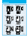
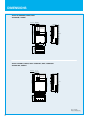
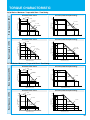
DIMENSIONS
・SJ700-055∼110 LFUF2,LFF2 /HFEF2, HFUF2,HFF2
・SJ700B-110∼150HFF
150(5.91)
130(5.12)
80(3.15)
Digital Operator
210(8.27)
80(3.15)
24.5(0.97)
246(9.69)
79(3.11)
2-φ7 (φ0.28)
169(6.65)
241(9.49)
255(10.04)
164(6.46)
Digital Operator
189(7.44)
Exhaust
79(3.11)
25(0.98)
2-φ6(φ0.24)
Wall
Wall
2-7(0.28)
189(7.44)
80(3.15)
82 (3.23)
・SJ700-300 LFUF2,LFF2 /HFEF2, HFUF2, HFF2
・SJ700B-370HFF
Digital Operator
Exhaust
45(1.77)
2-φ10
Air intake
195(7.68)
83(3.27)
190(7.48)
・SJ700-550 LFUF2,LFF2
Digital Operator
125(4.92) 80(3.15)
Digital Operator
2-φ12(φ0.47)
670(26.38)
352(13.87)
Wall
79(3.11)
Exhaust
550(21.65)
2-φ12(φ0.47)
520(20.47)
79(3.11)
277(10.91)
Exhaust
Wall
Air intake
5-41(φ1.61)
Wiring Hole
250(9.84)
300(11.81)
390(15.35)
5-φ25(φ0.98)
Wiring Hole
310(12.20)
・SJ700-370∼450 LFUF2,LFF2
・SJ700-370∼550 HFEF2, HFUF2,HFF2
・SJ700B-450∼750HFF
32.5(1.28) 80(3.15)
540(21.26)
510(20.08)
2-10(0.39)
9.5(0.37)
244(9.61)
Wall
Air intake
265(10.43)
2-12(0.47)
Exhaust
700(27.56)
3 -42x42.5(1.65x1.67)
Wiring Hole
368(14.49)
Wall
* Please refer to page 30 for detailed information about compatibility with SJ300.
2-12(0.47)
380(14.96)
480(18.90)
Air intake
6-φ41(φ1.61)
Wiring Hole
250(9.84)
229(9.02)
390(15.35)
376(14.80)
273.4(10.75)
2-7(0.28)
80(3.15)
79(3.11)
79(3.11)
24.5(0.97)
Digital Operator
13.6(0.25)
203 (7.99)
・SJ700-150∼220 LFUF2,LFF2 /HFEF2, HFUF2,HFF2
・SJ700B-185∼300HFF
250(9.84)
229(9.02)
170(6.69)
Air intake
143(5.63)
2-φ7(φ0.28)
Air intake
3 -33x28(1.30x1.10)
Wiring Hole
140(5.51)
3 -22x25(0.87x0.98)
Wiring Hole
130(5.12)
62(2.44)
2-6(0.24)
Exhaust
260(10.274)
・SJ700-004∼037 LFUF2, LFF2
・SJ700-007∼040HFEF2, HFUF2, 007∼037HFF2
[ Unit : mm(inch)]
Inches for reference only.
8
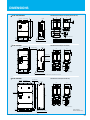
DIMENSIONS
・SJ700-750, 900HFEF2, HFUF2, HFF2
・SJ700B-900, 1100HFF
2-φ12(φ0.47)
32.5 80
(12.8) (3.15)
Exhaust
79(3.11)
Wall
357(14.06)
670(26.38)
700(27.56)
Digital Operator
Air intake
270(10.63)
2-12(0.47)
300(11.81)
390(15.35)
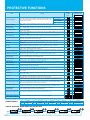
・SJ700-1100HFEF2, HFUF2, HFF2 / 1320HFEF2, HFF2, 1500HFUF2
・SJ700B-1320, 1600HFF
2-φ12(φ0.47)
62.5 80
(2.46) (3.15)
Exhaust
740(29.13)
710(27.95)
79(3.11)
Digital Operator
480(18.90)
Wall
Air intake
270(10.63)
2-12(0.47)
380(14.96)
480(18.90)
[ Unit : mm(inch)]
Inches for reference only.
9
DIMENSIONS
SJ700-1850,2200HFE2
2-M12 Eyebolts
15(0.59)
3-φ15(0.59)
Attachment DCreactor(DCL-H-185-H-R),(DCL-H-220-H-R)
305
150
Exhaust
W
Digital Operator
995(39.17)
965(37.99)
H
X
Wall
230
11x18
245
φ18
200
25
57.5
(22.63)
15
(0.59)
50
15(0.59)
290(11.41)
290(11.41)
2-M12 Eyebolts
15(0.59)
3-φ15(0.59)
Model
DCL-H-185-H-R
DCL-H-220-H-R
4-M12 Screw Holes For Eyebolts
695(27.36)
SJ700-3150HFE2
Downward details drawing
Air Intake
370(14.56)
57.5(2.26)
H
350
395
W
305
315
X
5
6
Attachment DCreactor(DCL-H-315-H-R)
Exhaust
2-M12 Screw Holes
325
365
150
Digital Operator
5
Wall
1300(51.18)
1270(50.0)
460
Vent Holes B(*1)
Vent Holes A(*1)
285
15x25
335
25
285
2-φ14
50
15
(0.59)
15(0.59)
50
(1.96)
290(11.41)
290(11.41)
680(26.77)
100
450(17.71)
50(1.96)
Air Intake
Downward details drawing
4-M12 Screw Holes For Eyebolts
*1 Vent-Holes A are formed on both right and left side portions. Vent-Holes B are just on right side.
SJ700-4000HFE2
Attachment DC reactor(DCL-H-400-H-R)
2-M16 Eyebolts
2-M16 Screw Holes
Exhaust
15(0.59)
4-φ15(0.59)
365
365
180
460
5
1700(66.92)
1670(65.74)
Digital Oprator
285
Wall
15x25
335
25
285
2-φ14
50
100
75(2.95)
15(0.59)
300(11.81)
300(11.81)
1050(41.33)
300(11.81)
15
(0.59)
Downward details drawing
75(2.95)
450(17.71)
Air Intake
4-M16 Screw Holes For Eyebolts
* 1850H,2200H,3150H and 4000H of US/JP Version:Please contact Hitachi sales office.
[ Unit : mm(inch)]
Inches for reference only.
10
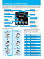
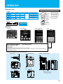
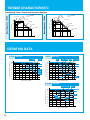
OPERATION and PROGRAMMING
SJ700 and SJ700B Series can be easily operated with the digital operator provided as standard. The digital operator can also be
detached and can be used for remote-control. Operator with copy function (WOP) and digital operator with potentiometer are also
available as options.
Parameter Display
Power LED
Lights when the power input
to the drive is ON.
Displays frequency, motor current,
rotational speed of the motor, and
an alarm code.
Monitor LEDs
ALARM LED
Shows drive status.
Lights to indicate that the
inverter has tripped.
RUN key enable LED
Lights up when the inverter
is ready to respond to the
RUN key.
Display Unit LEDs
Indicates the unit associated
with the parameter display.
RUN Key
Press to run the motor.
Store Key
STOP/RESET Key
Press to write the new value
to the EEPROM.
Press to stop the drive or
reset an alarm.
Up/Down Keys
Function Key
Press up or down to sequence
through parameters and functions
shown on the display, and
increment/decrement values.
Press to set or monitor a
parameter value.
Setting the output frequency
The contents of a basic mode display.(default)
Power on
(1) or the value previously
monitored is displayed.
(4)Preset value is displayed.
POWER
ALARM
POWER
ALARM
Hz
RUN
V
A
PRG
RUN
PRG
kW
Hz
V
A
kW
%
%
機能
機能
FUNC
記憶
FUNC
FUNC
FUNC
key.
(2)Function code appears.
STR
(5)Newly set value is displayed.
POWER
ALARM
ALARM
V
A
PRG
Press
to set desired value.
POWER
Hz
RUN
RUN
kW
%
PRG
Hz
V
A
No.
kW
%
機能
記憶
機能
STR
FUNC
Monitor display
3
F002
Acceleration (1) time setting
4
5
6
7
8
9
10
11
13
記憶
STR
14
Press
until
appears.
Press STR key
to store the value.
15
16
17
18
(3)
appears.
POWER
ALARM
(6)Returns to
and
the setting is complete.
Hz
RUN
V
A
PRG
POWER
kW
ALARM
%
RUN
PRG
機能
機能
11
FUNC
key.
20
21
22
23
記憶
25
A
kW
STR
FUNC
19
%
V
記憶
FUNC
Press
Hz
STR
*To run the motor, go back to
monitor mode or basic setting mode.
Item
d001 to d104
12
FUNC
Display code
1
2
記憶
STR
Press
If a desired parameter is not displayed, check the
setting of function "b037" (function code display
restriction). To display all parameters, specify "00" for
"b037".
24
26
27
28
29
F001
F003
F004
A001
A002
A003
A004
A005
A020
A021
A022
A023
A044
A045
A085
b001
b002
b008
b011
b037
b083
b084
b130
b131
C021
C022
C036
Output frequency setting
Deceleration (1) time setting
Operation direction setting
Frequency source setting
Run command source setting
Base frequency setting
Maximum frequency setting
[AT] selection
Multi-speed frequency setting
Multi-speed 1 setting
Multi-speed 2 setting
Multi-speed 3 setting
1st control method
V/f gain setting
Operation mode selection
Selection of restart mode
Allowable under-voltage power failure time
Retry-after-trip selection
Retry wait time after trip
Function code display restriction
Carrier frequency setting
Initialization mode selection
Selection of overvoltage suppression function
Setting of overvoltage suppression level
Setting of intelligent output terminal 11
Setting of intelligent output terminal 12
Alarm relay active state
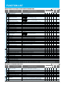
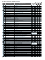
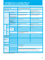
FUNCTION LIST
●MONITORING FUNCTIONS and MAIN PROFILE PARAMETERS
Monitor Mode
Code
d001
d002
d003
d004
Output frequency monitor
Output current monitor
Rotation direction minitoring
Process variable (PV), PID feedback monitor
d005
Intelligent input terminal status
d006
Intelligent output terminal status
d007
d008
d009
d010
d012
d013
d014
d015
d016
d017
d018
d019
Scaled output frequency monitoring
Actual-frequency monitoring
Torque command monitoring
Torque bias monitoring
Torque monitoring
Output voltage monitoring
Power monitoring
Cumulative power monitoring
Cumulative operation RUN time monitoring
Cumulative power-on time monitoring
Heat sink temperature monitoring
Motor temperature monitoring
d022
Life-check monitoring
d023
d024
d025
d026
d027
d028
d029
d030
d080
d081
d086
d090
d102
d103
d104
Program counter
Program number monitoring
User monitor 0
User monitor 1
User monitor 2
Pulse counter
Position setting monitor
Position feedback monitor
Trip Counter
F001
Output frequency setting
F002
F202
F302
F003
F203
F303
F004
A--b--C--H--P--U---
Acceleration (1) time setting
Acceleration (1) time setting, 2nd motor
Acceleration (1) time setting, 3rd motor
Deceleration (1) time setting
Deceleration time setting, 2nd motor
Deceleration time setting, 3rd motor
Keypad Run key routing
A Group: Standard functions
b Group: Fine tuning functions
C Group: Intelligent terminal functions
H Group: Motor constants functions
P Group: Expansion card functions
U Group: User-selectable menu functions
Setting Mode
-
Expanded Function
Function Name
Trip monitoring 1-6
Programming error monitoring
DC voltage monitoring
BRD load factor monitoring
Electronic thermal overload monitoring
Monitored data or setting
0.00 to 99.99, 100.0 to 400.0 (Hz) (*1)
0.0 to 999.9, 1000 to 9999 (A)
F (forward rotation), o (stopped), r (reverse rotation)
0.00 to 99.99, 100.0 to 999.9, 1000. to 9999. 1000 to 9999 (10000 to 99990),「100 to「999 (10000 to 999000)
FW
8 7 6 5 4 3 2 1
AL 15 14 13 12 11
-FE(CE) -FU(UL) -F(JP)
-
-
-
-
⃝
-
-
ON
OFF
(Example) FW, 7, 2, 1 : ON
8, 6, 5, 4, 3 : OFF
-
-
-
-
-
-
ON
OFF
(Example) 12, 11 : ON
AL, 15, 14, 13 :OFF
-
-
-
-
-
-
-
-
-
-
⃝
-
-
-
-
-
-
-
-
-
-
-
-
-
-
-
-
-
-
-
-
-
-
-
-
-
-
0.00 to 99.99, 100.0 to 999.9, 1000. to 9999., 1000 to 3996 (10000 to 39960)
-400. to -100., -99.9 to 0.00 to 99.99, 100.0 to 400.0 (Hz) (*2)
0. to +200. (%)
-200. to +200. (%)
-200. to +200. (%)
0.0 to 600.0 (V)
0.0 to 999.9 (kW)
0.0 to 999.9, 1000. to 9999.,1000 to 9999 (10000 to 99990),「100 to「999 (100000 to 999000)
0. to 9999., 1000 to 9999 (10000 to 99990),「100 to「999 (10000 to 999000) (hr)
0. to 9999., 1000 to 9999 (10000 to 99990),「100 to「999 (10000 to 999000) (hr)
-020. to 200.0 (℃)
-020. to 200.0 (℃)
2 1
[⃝= Allowed ×= Not permitted]
Default Setting
Change
Setting
during operation during operation
SJ700
SJ700B (allowed or not) (allowed or not)
ON
OFF
1: Capacitor on main circuit board
2: Cooling-fan speed drop
0 to 1024
0000 to 9999
-2147483647 to 2147483647 (upper 4 digits including “-“)
-2147483647 to 2147483647 (upper 4 digits including “-“)
-2147483647 to 2147483647 (upper 4 digits including “-“)
0 to 2147483647 (upper 4 digits)
-1073741823 to 1073741823 (upper 4 digits including “-“)
-1073741823 to 1073741823 (upper 4 digits including “-“)
0. to 9999., 1000 to 6553 (10000 to 65530) (times)
Factor, frequency (Hz), current (A), voltage across P-N (V),
running time (hours), power-on time (hours)
Warning code
0.0 to 999.9 (V)
0.0 to 100.0 (%)
0.0 to 100.0 (%)
0.0, "start frequency" to "maximum frequency" (or maximum frequency, 2nd/3rd motors) (Hz)
0.0 to 100.0 (when PID function is enabled)
0.01 to 99.99, 100.0 to 999.9, 1000. to 3600. (s)
0.01 to 99.99, 100.0 to 999.9, 1000. to 3600. (s)
0.01 to 99.99, 100.0 to 999.9, 1000. to 3600. (s)
0.01 to 99.99, 100.0 to 999.9, 1000. to 3600. (s)
0.01 to 99.99, 100.0 to 999.9, 1000. to 3600. (s)
0.01 to 99.99, 100.0 to 999.9, 1000. to 3600. (s)
00 (forward rotation), 01 (reverse rotation)
*)
*)
*
)
*))
*
0.00
0.00
0.00
0.00
⃝
⃝
30.00
30.00
30.00
30.00
30.00
30.00
00
30.00
30.00
30.00
30.00
30.00
30.00
00
30.00
30.00
30.00
30.00
30.00
30.00
00
30.00
30.00
30.00
30.00
30.00
30.00
00
⃝
⃝
⃝
⃝
⃝
⃝
×
⃝
⃝
⃝
⃝
⃝
⃝
×
*) Not available
(*1) 4000HF:0.00 to 99.99,100.0 to 120.0(Hz) (*2)4000HF: -120. to -100., -99.9 to 0.00 to 99.99,100.0 to 120.0(Hz)
●A GROUP: STANDARD FUNCTIONS
Analog input
and others
Basic settings
Code
Function Name
Monitored data or setting
[⃝= Allowed ×= Not permitted]
Default Setting
Change
Setting
during operation during operation
SJ700
SJ700B (allowed or not) (allowed or not)
-FE(CE) -FU(UL) -F(JP)
A001
Frequency source setting
00 (keypad potentiometer) (*1), 01 (control circuit terminal block),
02 (digital operator), 03 (RS485), 04 (option 1), 05 (option 2),
06 (pulse-string input), 07 (easy sequence), 10 (operation function result)
A002
A003
A203
A303
A004
A204
A304
Run command source setting
Base frequency setting
Base frequency setting, 2nd motor
Base frequency setting, 3rd motor
Maximum frequency setting
Maximum frequency setting, 2nd motor
Maximum frequency setting, 3rd motor
01 (control circuit terminal block), 02 (digital operator), 03 (RS485), 04 (option 1), 05 (option 2)
30. to "maximum frequency " (Hz)
30. to "maximum frequency, 2nd motor" (Hz)
30. to "maximum frequency, 3rd motor" (Hz)
30. to 400. (Hz) (*2)
30. to 400. (Hz) (*2)
30. to 400. (Hz) (*2)
01
50.
50.
50.
50.
50.
50.
01
60.
60.
60.
60.
60.
60.
02
60.
60.
60.
60.
60.
60.
01
50.
50.
50.
50.
50.
50.
×
×
×
×
×
×
×
×
×
×
×
×
×
×
A005
[AT] selection
00 (switching between O and OI terminals), 01 (switching between O and O2 terminals),
02 (switching between O terminal and keypad potentiometer) (*1), 03 (switching between OI terminal
and keypad potentiometer) (*1), 04 (switching between O2 and keypad potentiometer) (*1)
00
00
00
00
×
×
A006
[O2] selection
00 (single), 01 (auxiliary frequency input via O and OI terminals) (nonreversible),
02 (auxiliary frequency input via O and OI terminals) (reversible), 03 (disabling O2 terminal)
03
03
03
03
×
×
(*1) This setting is valid only when the OPE-SR is connected. (*2) 4000HF:30. to 120. (Hz)
01
01
02
01
×
×
12
V/f Characteristic
Multispeed operation and Jogging Analog input and others
Code
DC Braking
Frequency Upper/Lower Limit and Jump Frequency
PID Control
0.00
0.00
0.
100.
01
31.
00
00
0.00
0.00
0.00
0.00
0.00
0.
100.
01
31.
00
00
0.00
0.00
0.00
×
×
×
×
×
×
×
×
○
○
○
⃝
⃝
⃝
⃝
⃝
⃝
×
×
○
○
○
Multispeed 1-15 setting
0.0 or “start frequency” to “n-th maximum frequency” (Hz)
0.00
0.00
0.00
0.00
○
○
Jog frequency setting
"Start frequency" to 9.99 (Hz)
00 (free-running after jogging stops [disabled during operation]), 01 (deceleration and stop
after jogging stops [disabled during operation]), 02 (DC braking after jogging stops
[disabled during operation]), 03 (free-running after jogging stops [enabled during
operation]), 04 (deceleration and stop after jogging stops [enabled during operation]),
05 (DC braking after jogging stops [enabled during operation])
1.00
1.00
1.00
1.00
○
○
00
00
00
00
×
○
00
00
1.0
1.0
1.0
5.0
5.0
5.0
00
00
1.0
1.0
1.0
5.0
5.0
5.0
00
00
1.0
1.0
1.0
5.0
5.0
5.0
00
00
1.0
1.0
1.0
5.0
5.0
5.0
×
×
○
○
○
○
○
○
×
×
○
○
○
○
○
○
A039
Jog stop mode
A041
A241
A042
A242
A342
A043
A243
A343
Torque boost method selection
Torque boost method selection, 2nd motor
Manual torque boost value
Manual torque boost value, 2nd motor
Manual torque boost value, 3rd motor
Manual torque boost frequency adjustment
Manual torque boost frequency adjustment, 2nd motor
Manual torque boost frequency adjustment, 3rd motor
A044
V/F characteristic curve selection, 1st motor
A244
A344
A045
A051
A052
A053
V/F characteristic curve selection, 2nd motor
V/F characteristic curve selection, 3rd motor
V/f gain setting
Voltage compensation gain setting
for automatic torque boost. 1st motor
Voltage compensation gain setting
for automatic torque boost, 2nd motor
Slippage compensation gain setting
for automatic torque boost, 1st motor
Slippage compensation gain setting
for automatic torque boost, 2nd motor
DC braking enable
DC braking frequency setting
DC braking wait time
A054
DC braking force during deceleration
A055
A056
DC braking time for deceleration
DC braking/edge or level detection for [DB] input
A057
A247
AVR
0.0 or “start frequency” to “maximum frequency, 2nd motor” (Hz)
0.0 or “start frequency” to “maximum frequency, 3rd motor” (Hz)
0.00
0.00
0.
100.
01
31.
00
00
0.00
0.00
0.00
0.00 to 99.99, 100.0 to 400.0 (Hz) (*2)
A046
-FE(CE) -FU(UL) -F(JP)
0.00
0.00
0.
100.
01
31.
00
00
0.00
0.00
0.00
O-L input active range start frequency
O-L input active range end frequency
O-L input active range start voltabe
O-L input active range end voltabe
O-L input active range start frequency selection
External frequency filter time constant
Easy sequence function selection
Multispeed operation selection
Multispeed frequency setting
Multispeed frequency setting, 2nd motor
Multispeed frequency setting, 3rd motor
A047
Operation Mode and acceleration/
deceleration function
Monitored data or setting
A011
A012
A013
A014
A015
A016
A017
A019
A020
A220
A320
A021
I
A035
A038
A246
13
Function Name
[⃝= Allowed ×= Not permitted]
Default Setting
Change
Setting
during operation during operation
SJ700
SJ700B (allowed or not) (allowed or not)
0.00 to 99.99, 100.0 to 400.0 (Hz) (*2)
0. to "[O]-[L] input active range end voltage" (%)
"[O]-[L] input active range start voltage" to 100. (%)
00 (external start frequency), 01 (0 Hz)
1. to 30. or 31. (500 ms filter ±0.1 Hz with hysteresis)
00 (disabling), 01 (enabling)
00 (binary: 16 speeds selectable with 4 terminals), 01 (bit: 8 speeds selectable with 7 terminals)
0.0 or “start frequency” to “maximum frequency” (Hz)
00(Manual torque boost) / 01(Automatic torque boost)
00(Manual torque boost) / 01(Automatic torque boost)
0.0 to 20.0 (%)
0.0 to 20.0 (%)
0.0 to 20.0 (%)
0.0 to 50.0 (%)
0.0 to 50.0 (%)
0.0 to 50.0 (%)
00 (VC), 01 (VP), 02 (free V/f), 03 (sensorless vector control),
04(*1) (0Hz-range sensorless vector), 05(*1) (vector with sensor)
00
00
00
00
×
×
00 (VC), 01 (VP), 02 (free V/f), 03 (sensorless vector control), 04 (0Hz-range sensorless vector)
00(VC), 01(VP)
20. to 100. (%)
00
00
100.
00
00
100.
00
00
100.
00
00
100.
×
×
○
×
×
○
0. to 255.
100.
100.
100.
100.
○
○
0. to 255.
100.
100.
100.
100.
○
○
0. to 255.
100.
100.
100.
100.
○
○
0. to 255.
100.
100.
100.
100.
○
○
00 (disabling), 01 (enabling), 02 (set frequency only)
0.00 to 99.99, 100.0 to 400.0 (Hz)(*2)
0.0 to 5.0 (s)
00
0.50
0.0
00
0.50
0.0
00
0.50
0.0
00
0.50
0.0
×
×
×
○
○
○
SJ700: 0. to 100. (%) <75 to 132kW:0. to 80./185kW and over:0. to 35.>
SJ700B: 0. to 70. (%) <90kW and over:0. to 50.>
0
0
0
0
×
○
00 (edge operation), 01 (level operation)
0.0
01
0.0
01
0.0
01
×
×
○
○
DC braking force for starting
SJ700: 0. to 100. (%) <75 to 132kW:0. to 80./185kW and over:0. to 35.>
SJ700B: 0. to 70. (%) <90kW and over:0. to 50.>
0.0
01
0.
0.
0.
0.
×
○
A058
DC braking time for starting
0.0 to 60.0(s)
0.0
0.0
0.0
×
○
A059
DC braking carrier frequency setting
SJ700: 0.5 to 15.0(kHz) <75 to 132kW:0.5 to 10.0/185kW and over:0.5 to 3.0>
SJ700B: 0.5 to 12.0 (kHz) <90kW and over:0.5 to 8.0>
0.0
5.0
5.0
5.0
3.0
×
×
A061
A261
A062
A262
A063
A064
A065
A066
A067
A068
A069
A070
A071
A072
A073
A074
A075
Frequency upper limit setting
Frequency upper limit setting, 2nd motor
Frequency lower limit setting
Frequency lower limit setting, 2nd motor
Jump (center) frequency setting 1
Jump (hysteresis) frequency width setting 1
Jump (center) frequency setting 2
Jump (hysteresis) frequency width setting 2
Jump (center) frequency setting 3
Jump (hysteresis) frequency width setting 3
Acceleration stop time frequency setting
Acceleration stop time frequency setting
PID function enable
PID proportional gain
PID integral time constant
PID derivative gain
PV scale conversion
0.00 or "1st minimum frequency limit" to "maximum frequency" (Hz)
0.00 or "2nd minimum frequency limit" to "maximum frequency, 2nd motor" (Hz)
0.00 or "start frequency" to "maximum frequency limit" (Hz)
0.00 or "start frequency" to "maximum frequency, 2nd motor limit" (Hz)
0.00 to 99.99, 100.0 to 400.0 (Hz)(*2)
0.00 to 10.00 (Hz)
0.00 to 99.99, 100.0 to 400.0 (Hz)(*2)
0.00 to 10.00 (Hz)
0.00 to 99.99, 100.0 to 400.0 (Hz)(*2)
0.00 to 10.00 (Hz)
0.00 to 99.99, 100.0 to 400.0 (Hz)(*2)
0.0 to 60.0 (s)
00 (disabling), 01 (enabling), 02 (enabling inverted-data output)
0.2 to 5.0
0.0 to 999.9, 1000. to 3600.0 (s)
0.00 to 99.99, 100.0 (s)
0.01 to 99.99
0.00
0.00
0.00
0.00
0.00
0.50
0.00
0.50
0.00
0.50
0.00
0.0
00
1.0
1.0
0.00
1.00
0.00
0.00
0.00
0.00
0.00
0.50
0.00
0.50
0.00
0.50
0.00
0.0
00
1.0
1.0
0.00
1.00
0.00
0.00
0.00
0.00
0.00
0.50
0.00
0.50
0.00
0.50
0.00
0.0
00
1.0
1.0
0.00
1.00
×
×
×
×
×
×
×
×
×
×
×
×
×
○
○
○
×
○
○
○
○
○
○
○
○
○
○
○
○
○
○
○
○
○
A076
PV source setting
00 (input via OI), 01 (input via O), 02 (external communication),
03 (pulse-string frequency input), 10 (operation result output)
0.00
0.00
0.00
0.00
0.00
0.50
0.00
0.50
0.00
0.50
0.00
0.0
00
1.0
1.0
0.00
1.00
00
00
00
00
×
○
A077
A078
A081
A082
A085
A086
A092
A292
A392
A093
A293
A393
Output of inverted PID deviation
PID variation range
AVR function select
AVR voltage select
Operation mode selection
Energy saving mode tuning
Acceleration (2) time setting
Acceleration (2) time setting, 2nd motor
Acceleration (2) time setting, 3rd motor
Deceleration (2) time setting
Deceleration (2) time setting, 2nd motor
Deceleration (2) time setting, 3rd motor
00(OFF), 01 (ON)
0.0 to 100.0 (%)
00 (always on), 01 (always off), 02 (off during deceleration)
200 V class: 200, 215, 220, 230, 240 (V) 400 V class: 380, 400, 415, 440, 460, 480 (V)
00(Normal operation)/ 01(Energy-saving operation)/ 02(Fuzzy operation)
0.1 to 100.0
0.01 to 99.99, 100.0 to 999.9, 1000. to 3600. (s)
0.01 to 99.99, 100.0 to 999.9, 1000. to 3600. (s)
0.01 to 99.99, 100.0 to 999.9, 1000. to 3600. (s)
0.01 to 99.99, 100.0 to 999.9, 1000. to 3600. (s)
0.01 to 99.99, 100.0 to 999.9, 1000. to 3600. (s)
0.01 to 99.99, 100.0 to 999.9, 1000. to 3600. (s)
00
0.0
00
230/460
00
50.0
15.00
15.00
15.00
15.00
15.00
15.00
00
0.0
00
230/400
00
50.0
15.00
15.00
15.00
15.00
15.00
15.00
00
0.0
00
200/400
00
50.0
15.00
15.00
15.00
15.00
15.00
15.00
00
0.0
00
200/400
00
50.0
15.00
15.00
15.00
15.00
15.00
15.00
×
×
×
×
×
○
○
○
○
○
○
○
○
○
×
×
×
○
○
○
○
○
○
○
0.0 to 60.0 (s)
(*1) Derating is applied for SJ700B. Please consult technician at Hitachi or its distributor before use. (*2) 4000HF:0.00 to 99.99,100.0 to 120.0(Hz)
Acceleration
and deceleration
Operation-target frequency
Acceleration
and
deceleration
External frequency adjustment
Code
Function Name
Monitored data or setting
A094
Select method to switch to Acc2/Dec2 profile
00 (switching by 2CH terminal), 01 (switching by setting),
02 (switching only when rotation is reversed)
A294
Select method to switch to Acc2/Dec2, 2nd motor
00 (switching by 2CH terminal), 01 (switching by setting),
02 (switching only when rotation is reversed)
A095
A295
A096
A296
A097
A098
A101
A102
A103
A104
A105
A111
A112
A113
A114
A131
A132
Acc1 to Acc2 frequency transition point
Acc1 to Acc2 frequency transition point, 2nd motor
Dec1 to Dec2 frequency transition point
Dec1 to Dec2 frequency transition point, 2nd motor
Acceleration curve selection
Deceleration curve selection
OI-L input active range start frequency
OI-L input active range end frequency
OI-L input active range start current
OI-L input active range end current
OI-L input start frequency enable
O2-L input active range start frequency
O2-L input active range end frequency
O2-L input active range start voltage
O2-L input active range end voltage
Acceleration curve constants setting
Deceleration curve constants setting
A141
Operation-target frequency selection 1
01 (smallest swelling) to 10 (largest swelling)
01 (smallest swelling) to 10 (largest swelling)
00 (digital operator), 01 (keypad potentiometer), 02 (input via O), 03 (input via OI),
04 (external communication), 05 (option 1), 06 (option 2), 07 (pulse-string frequency input)
A142
Operation-target frequency selection 2
00 (digital operator), 01 (keypad potentiometer), 02 (input via O), 03 (input via OI),
04 (external communication), 05 (option 1), 06 (option 2), 07 (pulse-string frequency input)
A143
A145
A146
A150
A151
A152
A153
Operator selection
Frequency to be added
Sign of the frequency to be added
EL-S-curve acceleration ratio 1
EL-S-curve acceleration ratio 2
EL-S-curve deceleration ratio 1
EL-S-curve deceleration ratio 2
0.00 to 99.99, 100.0 to 400.0 (Hz) (*1)
0.00 to 99.99, 100.0 to 400.0 (Hz) (*1)
0.00 to 99.99, 100.0 to 400.0 (Hz) (*1)
0.00 to 99.99, 100.0 to 400.0 (Hz) (*1)
00 (linear), 01 (S curve), 02 (U curve), 03 (inverted-U curve), 04 (EL-S curve)
00 (linear), 01 (S curve), 02 (U curve), 03 (inverted-U curve), 04 (EL-S curve)
0.00 to 99.99, 100.0 to 400.0 (Hz) (*1)
0.00 to 99.99, 100.0 to 400.0 (Hz) (*1)
0. to "[OI]-[L] input active range end current" (%)
"[OI]-[L] input active range start current" to 100. (%)
00 (external start frequency), 1 (0 Hz)
-400. to -100., -99.9 to 0.00 to 99.99, 100.0 to 400.0 (Hz) (*2)
-400. to -100., -99.9 to 0.00 to 99.99, 100.0 to 400.0 (Hz) (*2)
-100. to 02 end-frequency rate (%)
"02 start-frequency rate" to 100. (%)
00 (addition: A141 + A142), 01 (subtraction: A141 - A142), 02 (multiplication: A141 x A142)
0.00 to 99.99, 100.0 to 400.0 (Hz) (*1)
00 (frequency command + A145), 01 (frequency command - A145)
0. to 50. (%)
0. to 50. (%)
0. to 50. (%)
0. to 50. (%)
(*1) 4000HF:0.00 to 99.99, 100.0 to 120.0(Hz) (*2) -120. to -100., -99.9 to 0.00 to 99.99 ,100.0 to 120.0(Hz)
[⃝= Allowed ×= Not permitted]
Default Setting
Change
Setting
during operation during operation
SJ700
SJ700B (allowed or not) (allowed or not)
-FE(CE) -FU(UL) -F(JP)
00
×
×
00
00
×
×
0.00
0.00
0.00
0.00
00
00
0.00
0.00
20.
100.
00
0.00
0.00
-100.
100.
02
02
0.00
0.00
0.00
0.00
00
00
0.00
0.00
20.
100.
00
0.00
0.00
-100.
100.
02
02
0.00
0.00
0.00
0.00
00
00
0.00
0.00
20.
100.
00
0.00
0.00
-100.
100.
02
02
×
×
×
×
×
×
×
×
×
×
×
×
×
×
×
×
×
×
×
×
×
×
×
×
○
○
○
○
○
○
○
○
○
○
02
02
02
02
×
○
03
03
03
03
×
○
00
0.00
00
25.
25.
25.
25.
00
0.00
00
25.
25.
25.
25.
00
0.00
00
25.
25.
25.
25.
00
0.00
00
25.
25.
25.
25.
×
×
×
×
×
×
×
○
○
○
×
×
×
×
00
00
00
00
00
0.00
0.00
0.00
0.00
00
00
0.00
0.00
20.
100.
00
0.00
0.00
-100.
100.
02
02
●B GROUP: FINE TUNING FUNCTIONS
Overload restriction and overcurrent restraint
Electronic thermal function
Restart after instantaneous power failure or tripping
Code
Function Name
Monitored data or setting
00 (tripping), 01 (starting with 0 Hz), 02 (starting with matching frequency), 03 (tripping after
deceleration and stopping with matching frequency), 04 (restarting with active matching frequency)
[⃝= Allowed ×= Not permitted]
Default Setting
Change
Setting
during operation during operation
SJ700
SJ700B (allowed or not) (allowed or not)
-FE(CE) -FU(UL) -F(JP)
00
×
○
1.0
1.0
×
×
○
○
00
00
×
○
00
00
00
×
○
00
0.00
00
0.00
00
0.00
×
×
○
○
00
00
00
00
×
○
00
00
00
00
×
○
3
3
3
3
×
○
1.0
×
○
×
○
×
○
00
00
b001
Selection of restart mode
b002
b003
b004
Allowable under-voltage power failure time
Retry wait time before motor restart
Instantaneous power failure/under-voltage
trip alarm enable
00 (disabling), 01 (enabling), 02 (disabling during stopping and decelerating to stop)
00
00
b005
Number of restarts on power
failure/under-voltage trip events
00 (16 times), 01 (unlimited)
00
b006
b007
Phase loss detection enable
Restart frequency threshold
00 (disabling), 01 (enabling)
0.00 to 99.99, 100.0 to 400.0 (Hz) (*2)
b008
Selection of retry after tripping
00 (tripping), 01 (starting with 0 Hz), 02 (starting with matching frequency), 03 (tripping after
deceleration and stopping with matching frequency), 04 (restarting with active matching frequency)
00
0.00
Selection of retry after undervoltage
00 (16 times), 01 (unlimited)
b009
b010
b011
Selection of retry count after overvoltage
or overcurrent
0.3 to 25.0 (s)
0.3 to 100.0 (s)
1 to 3 (times)
b012
Retry wait time after tripping
Electronic thermal setting (calculated within
the inverter from current output)
b212
Electronic thermal setting (calculated within
the inverter from current output), 2nd motor
0.20 x "rated current" to 1.00 x "rated current" (A)
b312
Electronic thermal setting (calculated within
the inverter from current output), 3rd motor
0.20 x "rated current" to 1.00 x "rated current" (A)
b013
b213
b313
b015
b016
b017
b018
b019
b020
Electronic thermal characteristic
Electronic thermal characteristic, 2nd motor
Electronic thermal characteristic, 3rd motor
Free-setting electronic thermal frequency (1)
Free-setting electronic thermal current (1)
Free-setting electronic thermal frequency (2)
Free-setting electronic thermal current (2)
Free-setting electronic thermal frequency (3)
Free-setting electronic thermal current (3)
00 (reduced-torque characteristic), 01 (constant-torque characteristic), 02 (free setting)
00 (reduced-torque characteristic), 01 (constant-torque characteristic), 02 (free setting)
00 (reduced-torque characteristic), 01 (constant-torque characteristic), 02 (free setting)
0. to 400. (Hz)(*3)
0.00 to rated current (A)
0. to 400. (Hz)(*3)
0.00 to rated current (A)
0. to 400. (Hz)(*3)
0.00 to rated current (A)
b021
Overload restriction operation mode
00 (disabling), 01 (enabling during acceleration and deceleration), 02 (enabling during
constant speed), 03 (enabling during acceleration and deceleration (increasing the speed
during regeneration))
b022
Overload restriction setting
SJ700: 0.20 x "rated current" to 2.00 x "rated current" (A) < 75kW and over:0.20 x 1.80 >
SJ700B: 0.20 x "rated current" to 1.50 x "rated current" (A)
b023
Deceleration rate at overload restriction
b024
Overload restriction operation mode (2)
00 (disabling), 01 (enabling during acceleration and deceleration), 02 (enabling during
constant speed), 03 (enabling during acceleration and deceleration (increasing the speed
during regeneration))
b025
Overload restriction setting (2)
SJ700: 0.20 x "rated current" to 2.00 x "rated current" (A) < 75kW and over:0.20 x 1.80 >
SJ700B: 0.20 x "rated current" to 1.50 x "rated current" (A)
b026
b027
Deceleration rate at overload restriction (2)
Overcurrent suppression enable
0.10 to 30.00 (s)
00 (disabling), 01 (enabling)
0.3 to 100.0 (s)
00
1.0
1.0
1.0
1.0(*1) 1.0(*1) 1.0(*1)
1.0(*1) 1.0(*1) 1.0(*1)
0.20 x "rated current" to 1.00 x "rated current" (A)
0.10 to 30.00 (s)
(*1) 4000HF:5.0 (*2) 4000HF:0.00 to 99.99,100.0 to 120.0 (Hz) (*3) 4000HF:0. to 120.(Hz)
Rated current of
inverterx 1..0
×
○
01
01
01
0.
0.0
0.
0.0
0.
0.0
01
01
01
0.
0.0
0.
0.0
0.
0.0
00
00
00
0.
0.0
0.
0.0
0.
0.0
01
01
01
0.
0.0
0.
0.0
0.
0.0
×
×
×
×
×
×
×
×
×
○
○
○
○
○
○
○
○
○
01
01
01
01
×
○
Rated
current
x 1.20
×
○
1.00
×
○
01
×
○
Rated
current
x 1.20
×
○
×
×
○
○
Rated current x 1.50
1.00
1.00
1.00
01
01
01
Rated current x 1.50
1.00
01
1.00
01
1.00
01
1.00
01
14
Free setting of V/f characteristic
Others
Window comparator
Non-stop operation at
momentary power failure
Torque limitation
Others
software Overload restriction and
overcurrent restraint
lock
Code
15
Function Name
Monitored data or setting
b028
Active frequency matching, scan start frequency
SJ700: 0.20 x "rated current" to 2.00 x "rated current" (A) < 75kW and over:0.20 x 1.50 >
SJ700B: 0.20 x "rated current" to 1.50 x "rated current" (A)
b029
b030
Active frequency matching, scan-time constant
Active frequency matching, restart frequency select
b031
Software lock mode selection
b034
RUN/ power-on warning time
b035
Rotational direction restriction
b036
Reduced voltage start selection
b037
Function code display restriction
00 (full display), 01 (function-specific display), 02 (user setting), 03 (data comparison
display), 04 (basic display)
b038
Initial-screen selection
b039
Automatic user-parameter setting function enable
0.10 to 30.00 (s)
00 (frequency at the last shutoff), 01 (maximum frequency), 02 (set frequency)
00 (disabling change of data other than "b031" when SFT is on), 01 (disabling change
of data other than "b031" and frequency settings when SFT is on), 02 (disabling change
of data other than "b031"), 03 (disabling change of data other than "b031" and
frequency settings), 10 (enabling data changes during operation)
0. to 9999. (0 to 99990), 1000 to 6553 (10000 to 655300) (hr)
[⃝= Allowed ×= Not permitted]
Default Setting
Change
Setting
during operation during operation
SJ700
SJ700B
(allowed or not) (allowed or not)
-FE(CE) -FU(UL) -F(JP)
Rated current of inverterx 1..0
×
○
0.50
00
0.50
00
0.50
00
0.50
00
×
×
○
○
01
01
01
01
×
○
0.
0.
0.
0.
×
○
00
00
00
00
×
×
06
06
06
06
×
○
04
04
04
04
×
○
00 (screen displayed when the STR key was pressed last), 01 (d001), 02 (d002),
03 (d003), 04 (d007), 05 (F001)
01
01
01
01
×
○
00
00
00
00
×
○
b040
Torque limit selection
00 (disabling), 01 (enabling)
00 (quadrant-specific setting), 01 (switching by terminal), 02 (analog input), 03 (option 1),
04 (option 2)
00
00
00
00
×
○
b041
Torque limit(1)
(Forward-driving in 4-quadrant mode)
SJ700: 0. to 200. (%), no (disabling torque limitation) < 75kW and over:0. to 180.>
SJ700B: 0. to 150.(%), no (disabling torque limitation)
150.
150.
150.
120.
×
○
b042
Torque limit(2)
(Reverse-regenerating in 4-quadrant mode)
SJ700: 0. to 200. (%), no (disabling torque limitation) < 75kW and over:0. to 180.>
SJ700B: 0. to 150.(%), no (disabling torque limitation)
150.
150.
150.
120.
×
○
b043
Torque limit(3)
(Reverse-driving in 4-quadrant mode)
SJ700: 0. to 200. (%), no (disabling torque limitation) < 75kW and over:0. to 180.>
SJ700B: 0. to 150.(%), no (disabling torque limitation)
150.
150.
150.
120.
×
○
b044
Torque limit(4)
(Forward-regenerating in 4-quadrant mode)
SJ700: 0. to 200. (%), no (disabling torque limitation) < 75kW and over:0. to 180.>
SJ700B: 0. to 150.(%), no (disabling torque limitation)
150.
150.
150.
120.
×
○
b045
b046
b050
b051
b052
b053
b054
b055
b056
b060
b061
b062
b063
b064
b065
b066
b067
b068
b070
b071
b072
b078
b079
b082
Torque limit LADSTOP enable
Reverse RUN protection enable
Controlled deceleration and stop on power loss
DC bus voltage trigger level during power loss
Over-voltage threshold during power loss
Deceleration time setting during power loss
Initial output frequency decrease during power loss
Proportional gain setting for nonstop operation at power loss
Integral time setting for nonstop operation at power loss
Maximum-limit level of window comparators O
Minimum-limit level of window comparators O
Hysteresis width of window comparators O
Maximum-limit level of window comparators OI
Minimum-limit level of window comparators OI
Hysteresis width of window comparators OI
Maximum-limit level of window comparators OI
Minimum-limit level of window comparators O/OI/O2
Hysteresis width of window comparators O/OI/O2
Operation level at O disconnection
Operation level at OI disconnection
Operation level at O2 disconnection
Cumulative input power data clearance
Cumulative input power display gain setting
Start frequency adjustment
00 (disabling), 01 (enabling)
00
00
00
00
00
00
00
00
00
00
00
00
1.00
0.00
0.20
0.100
100
0
0
100
0
0
100
-100
0
255(no)
255(no)
127(no)
00
1.
0.50
1.00
0.00
0.20
0.100
100
0
0
100
0
0
100
-100
0
255(no)
255(no)
127(no)
00
1.
0.50
1.00
0.00
0.20
0.100
100
0
0
100
0
0
100
-100
0
255(no)
255(no)
127(no)
00
1.
0.50
○
○
×
×
×
×
×
○
○
○
○
○
○
○
○
○
○
○
○
○
○
○
×
○
b083
Carrier frequency setting
SJ700: 0.5 to 15.0(kHz) <75 to 132kW:0.5 to 10.0/185kW and over:0.5 to 3.0>
SJ700B: 0.5 to 12.0 (kHz) <90kW and over:0.5 to 8.0.>
1.00
0.00
0.20
0.100
100
0
0
100
0
0
100
-100
0
255(no)
255(no)
127(no)
00
1.
0.50
×
×
×
×
×
×
×
○
○
○
○
○
○
○
○
○
○
○
×
×
×
○
×
×
5.0(*2) 5.0(*2) 5.0(*2) 3.0(*1)
×
×
b084
Initialization mode (parameters or trip history)
b085
b086
b087
00 (clearing the trip history), 01 (initializing the data), 02 (clearing the trip history and
initializing the data)
Country code for initialization
Frequency scaling conversion factor
STOP key enable
00 (Japan), 01 (EU), 02 (U.S.A.)
0.1 to 99.0
00 (enabling), 01 (disabling), 02 (disabling only the function to stop)
b088
Restart mode after FRS
b089
b090
b091
Automatic carrier frequency reduction
Dynamic braking usage ratio
Stop mode selection
b092
Cooling fan control
00: invalid, 01: valid
0.0 to 100.0 (%)
00 (deceleration until stop), 01 (free-run stop)
00 (always operating the fan), 01 (operating the fan only during inverter operation
[including 5 minutes after power-on and power-off])
b095
Dynamic braking control
00 (disabling), 01 (enabling [disabling while the motor is topped]), 02 (enabling [enabling
also while the motor is topped])
b096
Dynamic braking activation level
b098
Thermistor for thermal protection control
00 (disabling the thermistor), 01 (enabling the thermistor with PTC),
02 (enabling the thermistor with NTC)
b099
b100
b101
b102
b103
b104
b105
b106
b107
b108
b109
b110
b111
Thermal protection level setting
Free-setting V/f frequency (1)
Free-setting V/f voltage (1)
Free-setting V/f frequency (2)
Free-setting V/f voltage (2)
Free-setting V/f frequency (3)
Free-setting V/f voltage (3)
Free-setting V/f frequency (4)
Free-setting V/f voltage (4)
Free-setting V/f frequency (5)
Free-setting V/f voltage (5)
Free-setting V/f frequency (6)
Free-setting V/f voltage (6)
0. to 9999. (Ω)
0. to "free-setting V/f frequency (2)" (Hz)
0.0 to 800.0 (V)
0. to "free-setting V/f frequency (3)" (Hz)
0.0 to 800.0 (V)
0. to "free-setting V/f frequency (4)" (Hz)
0.0 to 800.0 (V)
0. to "free-setting V/f frequency (5)" (Hz)
0.0 to 800.0 (V)
0. to "free-setting V/f frequency (6)" (Hz)
0.0 to 800.0 (V)
0. to "free-setting V/f frequency (7)" (Hz)
0.0 to 800.0 (V)
00 (enabling both forward and reverse rotations), 01 (enabling only forward rotation),
02 (enabling only reverse rotation)
0 (minimum reduced voltage start time) to 255 (maximum reduced voltage start time)
00 (disabling), 01 (enabling)
00 (disabling), 01 (enabling)
0.0 to 999.9, 1000. (V)
0.0 to 999.9, 1000. (V)
0.01 to 99.99, 100.0 to 999.9, 1000. to 3600. (s)
0.00 to 10.00 (Hz)
0.00 to 2.55
0.0 to 9.999 /10.00 to 65.55
0. to 100. (lower limit : b061 + b062*2) (%)
0. to 100. (lower limit : b060 - b062*2) (%)
0. to 10. (lower limit : b061 - b062 / 2) (%)
0. to 100. (lower limit : b064 + b066*2) (%)
0. to 100. (lower limit : b063 - b066*2) (%)
0. to 10. (lower limit : b063 - b064 / 2) (%)
-100. to 100. (lower limit : b067 + b068*2) (%)
-100. to 100. (lower limit : b066 - b068*2) (%)
0. to 10. (lower limit : b066 - b067 / 2) (%)
0 to 100 (%) or "no" (ignore)
0 to 100 (%) or "no" (ignore)
0 to 100 (%) or "no" (ignore)
Clearance by setting "01" and pressing the STR key
1. to 1000.
0.10 to 9.99 (Hz)
00 (starting with 0 Hz), 01 (starting with matching frequency), 02 (starting with active
matching frequency)
330 to 380, 660 to 760(V)
220.0/440.0 220.0/440.0 220.0/440.0 220.0/440.0
360.0/720.0 360.0/720.0 360.0/720.0 360.0/720.0
00
00
00
00
×
×
01
1.0
00
02
1.0
00
00
1.0
00
01
1.0
00
×
○
×
×
○
○
00
00
00
00
×
○
00
0.0
00
00
0.0
00
00
0.0
00
00
0.0
00
×
×
×
×
○
○
00
00
00
00
×
○
00
00
00
00
×
○
×
○
×
○
×
×
×
×
×
×
×
×
×
×
×
×
×
○
×
×
×
×
×
×
×
×
×
×
×
×
360/720 360/720 360/720 360/720
00
00
00
00
3000. 3000. 3000. 3000.
0.
0.
0.
0.
0.0
0.0
0.0
0.0
0.
0.
0.
0.
0.0
0.0
0.0
0.0
0.
0.
0.
0.
0.0
0.0
0.0
0.0
0.
0.
0.
0.
0.0
0.0
0.0
0.0
0.
0.
0.
0.
0.0
0.0
0.0
0.0
0.
0.
0.
0.
0.0
0.0
0.0
0.0
(*1) “Over current protection” , ” Overload restriction” , “Over current limiting” and “Electronic thermal protection” might operate from the set value when “Carrier frequency setting” is used
with less than 2kHz by a low value. Please set to 2kHz or more and use the setting of “Carrier frequency setting” for such a situation. (*2) 1850HF, 2200HF and 3150HF:2.1, 4000HF:1.9
Others
Free setting
of V/f
characteristic
Code
b112
b113
b120
b121
b122
b123
b124
b125
b126
b127
b130
b131
b132
b133
b134
Function Name
Free-setting V/f frequency (7)
Free-setting V/f voltage (7)
Brake control enable
Brake wait time for release
Brake wait time for acceleration
Brake wait time for stopping
Brake wait time for confirmation
Brake release frequency setting
Brake release current setting
Braking frequency
Overvoltage suppression enable
Overvoltage suppression level
Acceleration and deceleration rate
at overvoltage suppression
Overvoltage suppression propotional gain
Overvoltage suppression Integral time
Monitored data or setting
0.0 to 400.0 (Hz) (*1)
0.0 to 800.0 (V)
00 (disabling), 01 (enabling)
0.00 to 5.00 (s)
0.00 to 5.00 (s)
0.00 to 5.00 (s)
0.00 to 5.00 (s)
0.00 to 99.99, 100.0 to 400.0 (Hz) (*2)
0.0 to 2.00 x "rated current"
0.00 to 99.99, 100.0 to 400.0 (Hz) (*2)
00 (disabling the restraint), 01 (decelerating and stagnating), 02 (enabling acceleration)
330 to 390 (V) (200 V class model), 660 to 780 (V) (400 V class model)
[⃝= Allowed ×= Not permitted]
Default Setting
Change
Setting
during operation during operation
SJ700
SJ700B
-FE(CE) -FU(UL) -F(JP)
×
×
○
○
○
○
○
○
○
○
○
○
0.00 to 2.55
1.00
×
○
0.50 0.50 0.50 0.50
0.060 0.060 0.060 0.060
○
○
0.000 to 9.999 / 10.00 to 63.53 (s)
○
○
(*1) 4000HF: 0.0 to 120.0(Hz) (*2)4000HF: 0.00 to 99.99, 100.0 to 120.0(Hz)
●C GROUP: INTELLIGENT TERMINAL FUNCTIONS
Analog monitoring
Intelligent output terminals
Intelligent input terminals
Intelligent input terminals
Code
Function Name
Monitored data or setting
01 (RV: Reverse RUN), 02 (CF1: Multispeed 1 setting), 03 (CF2: Multispeed 2 setting),
04 (CF3: Multispeed 3 setting), 05 (CF4: Multispeed 4 setting), 06 (JG: Jogging), 07 (DB:
external DC braking), 08 (SET: Set 2nd motor data), 09 (2CH: 2-stage
acceleration/deceleration), 11 (FRS: free-run stop), 12 (EXT: external trip), 13 (USP:
unattended start protection), 14: (CS: commercial power source enable), 15 (SFT: software
lock), 16 (AT: analog input voltage/current select), 17 (SET3: 3rd motor control), 18 (RS:
reset), 20 (STA: starting by 3-wire input), 21 (STP: stopping by 3-wire input), 22 (F/R:
forward/reverse switching by 3-wire input), 23 (PID: PID disable), 24 (PIDC: PID reset),
26 (CAS: control gain setting), 27 (UP: remote control UP function), 28 (DWN: remote
control DOWN function), 29 (DWN: remote control data clearing), 31 (OPE: forcible
operation), 32 (SF1: multispeed bit 1), 33 (SF2: multispeed bit 2), 34 (SF3: multispeed bit
3), 35 (SF4: multispeed bit 4), 36 (SF5: multispeed bit 5), 37 (SF6: multispeed bit 6),
38 (SF7: multispeed bit 7), 39 (OLR: overload restriction selection), 40 (TL: torque limit
enable), 41 (TRQ1: torque limit selection bit 1), 42 (TRQ2: torque limit selection bit 2),
43 (PPI: P/PI mode selection), 44 (BOK: braking confirmation), 45 (ORT: orientation), 46
(LAC: LAD cancellation), 47 (PCLR: clearance of position deviation), 48 (STAT: pulse train
position command input enable), 50 (ADD: trigger for frequency addition [A145]), 51 (F-TM:
forcible-terminal operation), 52 (ATR: permission of torque command input), 53 (KHC:
cumulative power clearance), 54 (SON: servo-on),
55 (FOC: pre-excitation), 56 (MI1: general-purpose input 1), 57 (MI2: general-purpose input
2), 58 (MI3: general-purpose input 3), 59 (MI4: general-purpose input 4), 60 (MI5:
general-purpose input 5), 61 (MI6: general-purpose input 6), 62 (MI7: general-purpose input 7),
63 (MI8: general-purpose input 8), 64 (EMR: Emergency stop)(*1), 65 (AHD: analog command
holding), 66 (CP1: multistage position settings selection 1 ), 67 (CP2: multistage position
settings selection 2), 68 (CP3: multistage position settings selection 3), 69 (ORL: Zero-return
limit function), 70 (ORG: Zero-return trigger function), 71 (FOT: forward drive stop), 72 (ROT:
reverse drive stop), 73 (SPD: speed / position switching), 74 (PCNT: pulse counter), 75 (PCC:
pulse counter clear), no (NO: no assignment)
0.
0.0
00
0.00
0.00
0.00
0.00
0.00
0.
0.0
00
0.00
0.00
0.00
0.00
0.00
1.00
1.00
18(RS) 18(RS) 18(RS) 18(RS)
×
○
16(AT) 16(AT) 16(AT) 16(AT)
×
○
06(JG) 06(JG) 06(JG) 06(JG)
×
○
11(FRS) 11(FRS) 11(FRS) 11(FRS)
×
○
09(2CH) 09(2CH) 09(2CH) 09(2CH)
×
○
03(CF2) 13(USP) 03(CF2) 03(CF2)
×
○
02(CF1) 02(CF1) 02(CF1) 02(CF1)
×
○
01(RV) 01(RV) 01(RV) 01(RV)
×
○
×
×
×
×
×
×
×
×
×
○
○
○
○
○
○
○
○
○
01(FA1) 01(FA1) 01(FA1) 01(FA1)
×
○
00(RUN) 00(RUN) 00(RUN) 00(RUN)
×
○
03(OL) 03(OL) 03(OL) 03(OL)
×
○
07(OTO) 07(OTO) 07(OTO) 07(OTO)
×
○
40(WAF) 40(WAF) 40(WAF) 40(WAF)
×
○
05(AL) 05(AL) 05(AL) 05(AL)
×
○
00
×
○
00
00
×
○
00
00
×
○
Terminal [2] function
C003
Terminal [3] function (*1)
C004
Terminal [4] function
C005
Terminal [5] function
C006
Terminal [6] function
C007
Terminal [7] function
C008
Terminal [8] function
C011
C012
C013
C014
C015
C016
C017
C018
C019
Terminal (1) active state
Terminal (2) active state
Terminal (3) active state
Terminal (4) active state
Terminal (5) active state
Terminal (6) active state
Terminal (7) active state
Terminal (8) active state
Terminal FW active state
C021
Terminal (11) function
C022
Terminal (12) function
C023
Terminal (13) function
C024
Terminal (14) function
C025
Terminal (15) function
C026
Alarm relay terminal function
C027
FM signal selection
00 (output frequency), 01 (output current), 02 (output torque), 03 (digital output frequency), 04 (output
voltage), 05 (input power), 06 (electronic thermal overload), 07 (LAD frequency), 08 (digital current
monitoring), 09 (motor temperature), 10 (heat sink temperature), 12 (general-purpose output YA0)
00
00
00
C028
AM signal selection
00 (output frequency), 01 (output current), 02 (output torque), 04 (output voltage), 05 (input power), 06
(electronic thermal overload), 07 (LAD frequency), 09 (motor temperature), 10 (heat sink temperature), 11
(output torque [signed value]), 13 (general-purpose output YA1)
00
00
C029
AMI signal selection
00 (output frequency), 01 (output current), 02 (output torque), 04 (output voltage), 05 (input power), 06
(electronic thermal overload), 07 (LAD frequency), 09 (motor temperature), 10 (heat sink temperature), 14
(general-purpose output YA2)
00
00
00 (RUN: running), 01 (FA1: constant-speed reached), 02 (FA2: set frequency overreached), 03 (OL:
overload notice advance signal (1)), 04 (OD: output deviation for PID control), 05 (AL: alarm signal),
06 (FA3: set frequency reached), 07 (OTQ: over-torque), 08 (IP: instantaneous power failure), 09 (UV:
undervoltage), 10 (TRQ: torque limited), 11 (RNT: operation time over), 12 (ONT: plug-in time over),
13 (THM: thermal alarm signal), 19 (BRK: brake release), 20 (BER: braking error), 21 (ZS: 0 Hz
detection signal), 22 (DSE: speed deviation maximum), 23 (POK: positioning completed),
24 (FA4: set frequency overreached 2), 25 (FA5: set frequency reached 2), 26 (OL2: overload notice
advance signal (2)), 27 (Odc: Analog O disconnection detection), 28 (OIDc: Analog OI disconnection
detection), 29 (O2Dc: Analog O2 disconnection detection), 31 (FBV: PID feedback comparison),
32 (NDc: communication line disconnection), 33 (LOG1: logical operation result 1), 34 (LOG2: logical
operation result 2), 35 (LOG3: logical operation result 3), 36 (LOG4: logical operation result 4),
37 (LOG5: logical operation result 5), 38 (LOG6: logical operation result 6), 39 (WAC: capacitor life
warning)(*2), 40 (WAF: cooling-fan speed drop), 41 (FR: starting contact signal), 42 (OHF: heat sink
overheat warning), 43 (LOC: low-current indication signal), 44 (M01: general-purpose output 1),
45 (M02: general-purpose output 2), 46 (M03: general-purpose output 3), 47 (M04: general-purpose
output 4), 48 (M05: general-purpose output 5), 49 (M06: general-purpose output 6), 50 (IRDY: inverter
ready), 51 (FWR: forward rotation), 52 (RVR: reverse rotation), 53 (MJA: major failure), 54(WCO:
window comparator O), 55(WCOI: window comparator OI), 56 (WCO2: window comparator O2)
(When alarm code output is selected for "C062", functions "AC0" to "AC2" or "AC0" to
"AC3" [ACn: alarm code output] are forcibly assigned to intelligent output terminals 11 to 13
or 11 to 14, respectively.)
(allowed or not) (allowed or not)
-FE(CE) -FU(UL) -F(JP)
C002
00(NO) / 01(NC)
00(NO) / 01(NC)
00(NO) / 01(NC)
00(NO) / 01(NC)
00(NO) / 01(NC)
*) Not available
[⃝= Allowed ×= Not permitted]
Default Setting
Change
Setting
during operation during operation
SJ700
SJ700B
Terminal [1] function (*1)
00(NO) / 01(NC)
00(NO) / 01(NC)
*
Rated current x 1.00
C001
00(NO) / 01(NC)
00(NO) / 01(NC)
0.
0.0 )
*
0.0 )
*
0.00 )
*
0.00 )
*
0.00 )
*
0.00 )
*
0.00 )
0.00 0.00 0.00 0.00 )
*
00
00
00
00
380/760 380/760 380/760 380/760
1.00
0.10 to 30.00 (s)
(allowed or not) (allowed or not)
×
×
×
×
×
×
×
×
×
×
×
×
0.
0.0
00
0.00
0.00
0.00
0.00
0.00
00
00
00
00
00
00
00
00
00
00
00
00
00
00
01
00
00
00
00
00
00
00
00
00
00
00
00
00
00
00
00
00
00
00
00
00
(*1) When the emergency stop function is enabled (SW1 = ON), "18" (RS) and "64" (EMR) are forcibly written to parameters "C001" and "C003",
respectively. (You cannot arbitrarily write "64" to "C001".) If the SW1 signal is turned off and then turned on, "no" (no assignment) is set in parameter "C003".
(*2) 1850HF,2200HF,3150HF and 4000HF:The function is not provided.
16
●C GROUP: INTELLIGENT TERMINAL FUNCTIONS
Function Name
Monitored data or setting
-FE(CE) -FU(UL) -F(JP)
Rated current of
inverterx 1..0
Digital current monitor reference value
C031
C032
C033
C034
C035
C036
Terminal (11) active state
Terminal (12) active state
Terminal (13) active state
Terminal (14) active state
Terminal (15) active state
Alarm relay terminal active state
00(NO) / 01(NC)
C038
Low-current indication signal output mode selection
00 (output during acceleration/deceleration and constant-speed operation),
01 (output only during constant-speed operation)
00
00
00
00
00
01
C039
Low-current indication signal detection level
SJ700:0.0 to 2.00 x "rated current" (A) / SJ700B:0.0 to 1.50 x "rated current" (A)
Rated current of inverterx 1..0
C040
Overload signal output mode
01
C041
C042
C043
C044
C045
C046
C052
C053
Overload level setting
Frequency arrival setting for accel.
Frequency arrival setting for decel.
PID deviation level setting
Frequency arrival setting for acceleration (2)
Frequency arrival setting for deceleration (2)
Maximum PID feedback data
Minimum PID feedback data
SJ700:0.0 to 2.00 x "rated current" (A) / SJ700B:0.0 to 1.50 x "rated current" (A)
Rated current of inverterx 1..0
0.00
0.00
3.0
0.00
0.00
100.0
0.0
0.00
0.00
3.0
0.00
0.00
100.0
0.0
C055
Over-torque(Forward-driving) level setting
SJ700: 0. to 200. (%) < 75kW and over:0. to 180.>
SJ700B: 0. to 150. (%)
0.00
0.00
3.0
0.00
0.00
100.0
0.0
100.
100.
Over-torque(Reverse-regenerating) level setting
SJ700: 0. to 200. (%) < 75kW and over:0. to 180.>
SJ700B: 0. to 150. (%)
100.
C057
Over-torque(Reverse-driving) level setting
SJ700: 0. to 200. (%) < 75kW and over:0. to 180.>
SJ700B: 0. to 150. (%)
C058
Over-torque(Forward-regenerating) level setting
SJ700: 0. to 200. (%) < 75kW and over:0. to 180.>
SJ700B: 0. to 150. (%)
C061
C062
C063
C064
C071
C072
C073
C074
C075
Electronic thermal warning level setting
Alarm code input
Zero speed detection level
Heat sink overheat warning level
Communication speed selection
Node allocation
Communication data length selection
Communication parity selection
Communication stop bit selection
C076
Selection of the operation after communication error
C077
C078
C079
C081
C082
C083
C085
C091
C101
Communication timeout limit before tripping
Communication wait time
Communication mode selection
O input span calibration
OI input span calibration
O2 input span calibration
Thermistor input tuning
Debug mode enable
UP/DOWN memory mode selection
C102
Reset mode selection
00 (resetting the trip when RS is on), 01 (resetting the trip when RS is off),
02 (enabling resetting only upon tripping [resetting when RS is on])
C103
Restart mode after reset
00 (starting with 0 Hz), 01 (starting with matching frequency),
02 (restarting with active matching frequency)
C105
C106
C107
C109
C110
FM gain adjustment
AM gain adjustment
AMI gain adjustment
AM bias adjustment
AMI bias adjustment
50. to 200. (%)
50. to 200. (%)
50. to 200. (%)
0. to 100. (%)
0. to 100. (%)
C111
Overload setting (2)
SJ700:0.0 to 2.00 x "rated current" (A) <75kW and over:0.0 to 1.80 x "rated current">
SJ700B:0.0 to 1.50 x "rated current" (A)
C121
C122
C123
C130
C131
C132
C133
C134
C135
C136
C137
C138
C139
C140
C141
C142
C143
C144
C145
C146
C147
C148
O input zero calibration
OI input zero calibration
O2 input zero calibration
Output 11 on-delay time
Output 11 off-delay time
Output 12 on-delay time
Output 12 off-delay time
Output 13 on-delay time
Output 13 off-delay time
Output 14 on-delay time
Output 14 off-delay time
Output 15 on-delay time
Output 15 off-delay time
Output RY on-delay time
Output RY off-delay time
Logical output signal 1 selection 1
Logical output signal 1 selection 2
Logical output signal 1 operator selection
Logical output signal 2 selection 1
Logical output signal 2 selection 2
Logical output signal 2 operator selection
Logical output signal 3 selection 1
0. to 9999., 1000 to 6553 (10000 to 65530)
0. to 9999., 1000 to 6553 (10000 to 65530)
0. to 9999., 1000 to 6553 (10000 to 65530)
0.0 to 100.0 (s)
0.0 to 100.0 (s)
0.0 to 100.0 (s)
0.0 to 100.0 (s)
0.0 to 100.0 (s)
0.0 to 100.0 (s)
0.0 to 100.0 (s)
0.0 to 100.0 (s)
0.0 to 100.0 (s)
0.0 to 100.0 (s)
0.0 to 100.0 (s)
0.0 to 100.0 (s)
Same as the settings of C021 to C026 (except those of LOG1 to LOG6)
Same as the settings of C021 to C026 (except those of LOG1 to LOG6)
00 (AND), 01 (OR), 02 (XOR)
Same as the settings of C021 to C026 (except those of LOG1 to LOG6)
Same as the settings of C021 to C026 (except those of LOG1 to LOG6)
00 (AND), 01 (OR), 02 (XOR)
Same as the settings of C021 to C026 (except those of LOG1 to LOG6)
Output terminal operation function
Adjustment Terminal Meter adjustment
Others
Adjustment
Communication function
Levels and output terminal status
Analog
monitoring
SJ700:0.20 x "rated current" to 2.00 x "rated current" (A) / SJ700B:0.20 x "rated current" to 1.50 x "rated current" (A)
(Current with digital current monitor output at 1,440 Hz)
C030
Intelligent
output terminals
Code
[⃝= Allowed ×= Not permitted]
Default Setting
Change
Setting
during operation during operation
SJ700
SJ700B (allowed or not) (allowed or not)
17
C056
00(NO) / 01(NC)
00(NO) / 01(NC)
00(NO) / 01(NC)
00(NO) / 01(NC)
00(NO) / 01(NC)
00 (output during acceleration/deceleration and constant-speed operation),
01 (output only during constant-speed operation)
0.00 to 99.99, 100.0 to 400.0 (Hz) (*1)
0.00 to 99.99, 100.0 to 400.0 (Hz) (*1)
0.0 to 100.0 (%)
0.00 to 99.99, 100.0 to 400.0 (Hz) (*1)
0.00 to 99.99, 100.0 to 400.0 (Hz) (*1)
0.0 to 100.0 (%)
0.0 to 100.0 (%)
0. to 100. (%)
00(Disabled) / 01(3-bit) / 02(4-bit)
0.00 to 99.99, 100.0 (Hz)
0. to 200.0 (℃)
02 (loopback test), 03 (2,400 bps), 04 (4,800 bps), 05 (9,600 bps), 06 (19,200 bps)
1. to 32.
7 (7 bits), 8 (8 bits)
00 (no parity), 01 (even parity), 02 (odd parity)
1 (1 bit), 2 (2 bits)
00 (tripping), 01 (tripping after decelerating and stopping the motor), 02 (ignoring errors),
03 (stopping the motor after free-running), 04 (decelerating and stopping the motor)
0.00 to 99.99 (s)
0. to 1000. (ms)
00(ASCII), 01(Modbus-RTU)
0. to 9999., 1000 to 6553(10000 to 65530)
0. to 9999., 1000 to 6553(10000∼65530)
0. to 9999., 1000 to 6553(10000∼65530)
0.0 to 999.9, 1000.
(Do not change this parameter, which is intended for factory adjustment.)
00 (not storing the frequency data), 01 (storing the frequency data)
(*1) 4000HF:0.00 to 99.99, 100.0 to 120.0(Hz)
○
○
00
00
00
00
00
01
00
00
00
00
00
01
00
00
00
00
00
01
×
×
×
×
×
×
○
○
○
○
○
○
01
01
01
×
○
×
○
×
○
0.00
0.00
3.0
0.00
0.00
100.0
0.0
×
×
×
×
×
×
×
×
○
○
○
○
○
○
○
○
100.
100.
×
○
100.
100.
100.
×
○
100.
100.
100.
100.
×
○
100.
100.
100.
100.
×
○
80.
00
0.00
120.
04
1.
7
00
1
80.
00
0.00
120.
04
1.
7
00
1
80.
00
0.00
120.
04
1.
7
00
1
80.
00
0.00
120.
04
1.
7
00
1
×
×
×
×
×
×
×
×
×
○
○
○
○
○
○
○
○
○
01
01
01
01
02
02
02
02
×
○
0.00
0.
00
0.00
0.
00
0.00
0.
00
0.00
0.
00
○
○
○
○
○
○
○
×
○
00
00
00
00
00
00
00
00
×
×
×
×
×
×
×
×
×
00
00
00
00
○
○
Factory set
00
00
00
00
×
○
100.
100.
100.
0.
20.
100.
100.
100.
0.
20.
100.
100.
100.
0.
20.
100.
100.
100.
0.
20.
○
○
○
○
○
○
○
○
○
○
×
○
○
○
○
○
×
×
×
×
×
×
×
×
×
×
×
×
×
×
×
×
×
×
○
○
○
○
○
○
○
○
○
○
○
○
○
○
○
○
○
○
○
○
○
○
Rated current of
inverterx 1..0
Factory set
0.0
0.0
0.0
0.0
0.0
0.0
0.0
0.0
0.0
0.0
0.0
0.0
00
00
00
00
00
00
00
0.0
0.0
0.0
0.0
0.0
0.0
0.0
0.0
0.0
0.0
0.0
0.0
00
00
00
00
00
00
00
0.0
0.0
0.0
0.0
0.0
0.0
0.0
0.0
0.0
0.0
0.0
0.0
00
00
00
00
00
00
00
0.0
0.0
0.0
0.0
0.0
0.0
0.0
0.0
0.0
0.0
0.0
0.0
00
00
00
00
00
00
00
other Input terminal response Output terminal operation function
Code
C149
C150
C151
C152
C153
C154
C155
C156
C157
C158
C159
C160
C161
C162
C163
C164
C165
C166
C167
C168
C169
Function Name
Logical output signal 3 selection 2
Logical output signal 3 operator selection
Logical output signal 4 selection 1
Logical output signal 4 selection 2
Logical output signal 4 operator selection
Logical output signal 5 selection 1
Logical output signal 5 selection 2
Logical output signal 5 operator selection
Logical output signal 6 selection 1
Logical output signal 6 selection 2
Logical output signal 6 operator selection
Input terminal response time setting 1
Input terminal response time setting 2
Input terminal response time setting 3
Input terminal response time setting 4
Input terminal response time setting 5
Input terminal response time setting 6
Input terminal response time setting 7
Input terminal response time setting 8
Input terminal response time setting FW
Multistage speed/position determination time
Monitored data or setting
Same as the settings of C021 to C026 (except those of LOG1 to LOG6)
00 (AND), 01 (OR), 02 (XOR)
Same as the settings of C021 to C026 (except those of LOG1 to LOG6)
Same as the settings of C021 to C026 (except those of LOG1 to LOG6)
00 (AND), 01 (OR), 02 (XOR)
Same as the settings of C021 to C026 (except those of LOG1 to LOG6)
Same as the settings of C021 to C026 (except those of LOG1 to LOG6)
00 (AND), 01 (OR), 02 (XOR)
Same as the settings of C021 to C026 (except those of LOG1 to LOG6)
Same as the settings of C021 to C026 (except those of LOG1 to LOG6)
00 (AND), 01 (OR), 02 (XOR)
0. to 200. (×2ms)
0. to 200. (×2ms)
0. to 200. (×2ms)
0. to 200. (×2ms)
0. to 200. (×2ms)
0. to 200. (×2ms)
0. to 200. (×2ms)
0. to 200. (×2ms)
0. to 200. (×2ms)
0. to 200. (×10ms)
[⃝= Allowed ×= Not permitted]
Default Setting
Change
Setting
during operation during operation
SJ700
SJ700B (allowed or not) (allowed or not)
-FE(CE) -FU(UL) -F(JP)
00
00
00
00
00
00
00
00
00
00
00
1
1
1
1
1
1
1
1
1
0
●H GROUP: MOTOR CONSTANTS FUNCTIONS
Code
00
00
00
00
00
00
00
00
00
00
00
1
1
1
1
1
1
1
1
1
0
×
×
×
×
×
×
×
×
×
×
×
×
×
×
×
×
×
×
×
×
×
○
○
○
○
○
○
○
○
○
○
○
○
○
○
○
○
○
○
○
○
○
[⃝= Allowed ×= Not permitted]
Default Setting
Change
Setting
during operation during operation
SJ700
SJ700B (allowed or not) (allowed or not)
-FE(CE) -FU(UL) -F(JP)
00 (disabling auto-tuning), 01 (auto-tuning without rotation),
02 (auto-tuning with rotation)
00
00
00
00
×
×
Motor data selection, 1st motor
00 (Hitachi standard data), 01 (auto-tuned data),
02 (auto-tuned data [with online auto-tuning function])
00
00
00
00
×
×
H202
Motor data selection, 2nd motor
00 (Hitachi standard data), 01 (auto-tuned data),
02 (auto-tuned data [with online auto-tuning function])
00
00
00
00
×
×
H003
H203
H004
H204
H005
H205
H006
H206
H306
H020
H220
H021
H221
H022
H222
H023
H223
H024
H224
H030
H230
H031
H231
H032
H232
H033
H233
H034
H234
H050
H250
H051
H251
H052
H252
H060
H260
H061
H261
H070
H071
H072
H073
Motor capacity, 1st motor
Motor capacity, 2nd motor
Motor poles setting, 1st motor
Motor poles setting, 2nd motor
Motor speed constant, 1st motor
Motor speed constant, 2nd motor
Motor stabilization constant, 1st motor
Motor stabilization constant, 2nd motor
Motor stabilization constant, 3rd motor
Motor constant R1, 1st motor
Motor constant R1, 2nd motor
Motor constant R2, 1st motor
Motor constant R2, 2nd motor
Motor constant L, 1st motor
Motor constant L, 2nd motor
Motor constant Io
Motor constant Io, 2nd motor
Motor constant J
Motor constant J, 2nd motor
Auto constant R1, 1st motor
Auto constant R1, 2nd motor
Auto constant R2, 1st motor
Auto constant R2, 2nd motor
Auto constant L, 1st motor
Auto constant L, 2nd motor
Auto constant Io, 1st motor
Auto constant Io, 2nd motor
Auto constant J, 1st motor
Auto constant J, 2nd motor
PI proportional gain for 1st motor
PI proportional gain for 2nd motor
PI integral gain for 1st motor
PI integral gain for 2nd motor
P proportional gain setting for 1st motor
P proportional gain setting for 2nd motor
Zero LV lmit for 1st motor
Zero LV lmit for 2nd motor
Zero LV starting boost current for 1st motor
Zero LV starting boost current for 2nd motor
Terminal selection PI proportional gain setting
Terminal selection PI integral gain setting
Terminal selection P proportional gain setting
Gain switching time
×
×
×
×
○
○
○
○
○
×
×
×
×
×
×
×
×
×
×
×
×
×
×
×
×
×
×
×
×
○
○
○
○
○
○
○
○
○
○
○
○
○
○
×
×
×
×
○
○
○
○
○
×
×
×
×
×
×
×
×
×
×
×
×
×
×
×
×
×
×
×
×
○
○
○
○
○
○
○
○
○
○
○
○
○
○
H002
Control constants
Monitored data or setting
00
00
00
00
00
00
00
00
00
00
00
1
1
1
1
1
1
1
1
1
0
Auto-tuning Setting
H001
Control constants
Function Name
00
00
00
00
00
00
00
00
00
00
00
1
1
1
1
1
1
1
1
1
0
SJ700:0.20 to 400.0 (kW)/SJ700B:0.20 to 160(kW)
SJ700:0.20 to 400.0 (kW)/SJ700B:0.20 to 160(kW)
2, 4, 6, 8, 10 (poles)
2, 4, 6, 8, 10 (poles)
0.001 to 9.999, 10.00 to 80.00 (10.000 to 80.000)
0.001 to 9.999, 10.00 to 80.00 (10.000 to 80.000)
0. to 255.
0. to 255.
0. to 255.
0.001 to 9.999, 10.00 to 65.53 (Ω) (*1)
0.001 to 9.999, 10.00 to 65.53 (Ω) (*1)
Factory set
4
4
4
4
4
4
4
4
1,590 1,590 1,590 1,590
1,590 1,590 1,590 1,590
100. 100. 100. 100.
100. 100. 100. 100.
100. 100. 100. 100.
0.001 to 9.999, 10.00 to 65.53 (Ω) (*1)
0.001 to 9.999, 10.00 to 65.53 (Ω) (*1)
0.01 to 99.99, 100.0 to 655.3 (mH) (*2)
0.01 to 99.99, 100.0 to 655.3 (mH) (*2)
0.01 to 99.99, 100.0 to 655.3 (A) (*3)
0.01 to 99.99, 100.0 to 655.3 (A) (*3)
0.001 to 9.999, 10.00 to 99.99, 100.0 to 999.9, 1000. to 9999.
0.001 to 9.999, 10.00 to 99.99, 100.0 to 999.9, 1000. to 9999.
0.001 to 9.999, 10.00 to 65.53 (Ω) (*1)
0.001 to 9.999, 10.00 to 65.53 (Ω) (*1)
0.001 to 9.999, 10.00 to 65.53 (Ω) (*1)
0.001 to 9.999, 10.00 to 65.53 (Ω) (*1)
0.01 to 99.99, 100.0 to 655.3 (mH) (*2)
0.01 to 99.99, 100.0 to 655.3 (mH) (*2)
0.01 to 99.99, 100.0 to 655.3 (A) (*3)
0.01 to 99.99, 100.0 to 655.3 (A) (*3)
0.001 to 9.999, 10.00 to 99.99, 100.0 to 999.9, 1000. to 9999.
0.001 to 9.999, 10.00 to 99.99, 100.0 to 999.9, 1000. to 9999.
0.0 to 999.9, 1000.
0.0 to 999.9, 1000.
0.0 to 999.9, 1000.
0.0 to 999.9, 1000.
0.01 to 10.00
0.01 to 10.00
0.0 to 100.0
0.0 to 100.0
0. to 50. (%)
0. to 50. (%)
0.0 to 999.9, 1000.
0.0 to 999.9, 1000.
0.00 to 10.00
0. to 9999. (ms)
(*1) 1850HF,2200HF,3150HF and 4000HF:0.1 to 999.9,1000. to 6553.(mΩ).
(*2) 1850HF,2200HF,3150HF and 4000HF:0.001 to 9.999,10.00. to 65.53(mH).
(*3) 1850HF,2200HF,3150HF and 4000HF:0.01 to 0.35 “ rated current ”(A).
Depending on
motor capacity
100.0
100.0
100.0
100.0
1.00
1.00
100.
100.
50.
50.
100.0
100.0
1.00
100.
100.0
100.0
100.0
100.0
1.00
1.00
100.
100.
50.
50.
100.0
100.0
1.00
100.
100.0
100.0
100.0
100.0
1.00
1.00
100.
100.
50.
50.
100.0
100.0
1.00
100.
100.0
100.0
100.0
100.0
1.00
1.00
70. )
*
70. )
*
50. )
*
50. )
*
100.0
100.0
1.00
100.
*) Not available
18
●P GROUP: EXPANSION CARD FUNCTIONS
Output terminal operation function
Code
P001
P002
P011
P012
P013
P014
P015
P016
P017
P018
P019
P020
P021
P022
P023
P024
P025
P026
P027
P028
P029
P031
P032
P033
P034
Monitored data or setting
-FE(CE) -FU(UL) -F(JP)
×
×
×
○
×
×
○
×
○
○
○
○
×
×
01
×
×
21
71
21
71
×
×
×
×
01
01
01
×
×
00
25.0
0.10
0.
100.
00
25.0
0.10
0.
100.
00
25.0
0.10
0.
100.
×
×
×
×
×
×
○
○
○
○
0
0
0
*)
00 (as indicated by the sign), 01 (depending on the operation direction)
00
00
00
00 (disabling the mode), 01 (digital operator), 02 (input via O2 terminal)
-200. to +200. (%)
00
0.
00
00
0.
00
00
0.
00
P039
Torque bias mode
Torque bias value
Torque bias polarity selection
Speed limit for torque-controlled operation
(forward rotation)
0.00 to "maximum frequency" (Hz)
0.00
0.00
0.00
P040
Speed limit for torque-controlled operation
(reverse rotation)
0.00 to "maximum frequency" (Hz)
0.00
0.00
0.00 0.00
DeviceNet comm watchdog timer
0.00 to 99.99 (s)
1.00
1.00
1.00
1.00
01
01
01
21
71
21
71
01
00
25.0
0.10
0.
100.
P035
P036
P037
P038
P045
Inverter action on DeviceNet comm error
P046
P047
DeviceNet polled I/O : Output instance number
DeviceNet polled I/O : input instance number
P048
Inverter action on DeviceNet idle mode
P049
P055
P056
P057
P058
P060
I
P067
P068
P069
P070
P071
P072
P073
P074
P100
I
P131
DeviceNet motor poles setting for RPM
Pulse-string frequency scale
Time constant of pulse-string frequency filter
Pulse-string frequency bias
Pulse-string frequency limit
Code
parameters
○
○
×
×
×
○
○
×
○
○
○
○
×
○
○
○
○
○
×
○
○
×
○
×
○
00 (tripping), 01 (continuing operation)
Multistage position setting 0-7
00 (tripping), 01 (continuing operation)
128. to 9999., 1000 to 6500 (10000 to 65000) (pulses)
00 (ASR), 01 (APR), 02 (APR2), 03 (HAPR)
00 (mode 0), 01 (mode 1), 02 (mode 2)
0. to 4095.
"start frequency" to "maximum frequency" (up to 120.0) (Hz)
00 (forward), 01 (reverse)
0. to 9999., 1000 (10000) (pulses)
0.00 to 9.99 (s)
00 (feedback side), 01 (commanding side)
0. to 9999.
0. to 9999.
0.00 to 99.99, 100.0 to 655.3
0.00 to 99.99, 100.0
-204 (-2048.) / -999. to 2048
00 (no compensation), 01 (compensation)
0.0 to 150.0 (%)
0.00 to 99.99, 100.0 to120.0 (Hz)
0. to 9999.
0. to 9999.
00 (digital operator), 01 (option 1), 02 (option 2), 03 (easy sequence)
00 (digital operator), 01 (option 1), 02 (option 2)
00 (O terminal), 01 (OI terminal), 02 (O2 terminal), 03 (digital operator)
0. to 200. (%)
00 (as indicated by the sign), 01 (depending on the operation direction)
00 (tripping), 01 (tripping after decelerating and stopping the motor), 02 (ignoring errors),
03 (stopping the motor after free-running), 04 (decelerating and stopping the motor)
20, 21, 100
70, 71, 101
00 (tripping), 01 (tripping after decelerating and stopping the motor), 02 (ignoring errors),
03 (stopping the motor after free-running), 04 (decelerating and stopping the motor)
0, 2, 4, 6, 8, 10, 12, 14, 16, 18, 20, 22, 24, 26, 28, 30, 32, 34, 36, 38 (poles)
1.0 to 50.0 (kHz)
0.01 to 2.00 (s)
-100. to +100. (%)
0. to 100. (%)
Position setting range reverse side – forward side
(upper 4 digits including “-“)
00(Low) / 01 (Hi1) / 00 (Hi2)
00 (FW) / 01 (RV)
Zero-return mode selection
Zero-return direction selection
Low-speed zero-return frequency
High-speed zero-return frequency
Position range specification (forward)
Position range specification (reverse)
Teaching selection
0.00 – 10.00 (Hz)
0.00 – 99.99 / 100.0 – Maximum frequency setting, 1st motor (Hz)
0 – 268435455 (when P012 = 02) 0 – 1073741823 (When P012 = 03) (upper 4 digits)
-268435455 – 0 (when P012 = 02) -1073741823 - 0 (When P012 = 03) (upper 4 digits)
00 (X00) / 01 (X01) / 02 (X02) / 03 (X03) /04 (X04) / 05 (X05) / 06 (X06) / 07 (X07)
Easy sequence user parameter U (00)-(31)
0. to 9999., 1000 to 6553 (10000 to 65535)
0
00
00
0.00
0.00
00
0.
U001
I
P012
Function Name
User selected functions 1-12
Monitored data or setting
no/d001 to P131
*
*)
00 )
*
0. )
*
00 )
*
0.00 )
*
00
*)
○
○
00
00
00 )
*
00
00
00 )
*
0.00 0.00 0.00 )
*
0.00 0.00 0.00 )
*
268435455 )
*
-268435455 )
* 00 )
00
00
○
○
○
○
○
○
○
○
○
○
○
○
○
○
0.
○
○
0.
*
0.
*
●U GROUP: USER-SELECTABLE MENU FUNCTIONS
19
×
×
×
×
×
×
×
×
×
×
×
×
×
×
×
×
×
×
×
×
×
×
×
×
○
00
00
00
00
00
00
00
00
1024 1024 1024 1024 )
*
00
00
00
00 )
*
00
00
00
00 )
*
0.
0.
0.
0. )
*
5.00 5.00 5.00 5.00 )
*
00
00
00
00 )
*
5.
5.
5.
5. )
*
0.00 0.00 0.00 0.00 )
*
00
00
00
00 )
*
1.
1.
1.
1. )
*
1.
1.
1.
1. )
*
0.00 0.00 0.00 0.00 )
*
0.50 0.50 0.50 0.50 )
*
0.
0.
0.
0. )
*
00
00
00
00
135.0 135.0 135.0 135.0 )
*
7.50 7.50 7.50 7.50 )
*
1.
1.
1.
1. )
*
1.
1.
1.
1. )
*
00
00
00
00
00
00
00
00 )
*
00
00
00
00 )
*
0.
0.
0.
0. )
Operation mode on expansion card 1 error
Operation mode on expansion card 2 error
Encoder pulse-per-revolution (PPR) setting
Control pulse setting
Pulse input mode setting
Home search stop position setting
Home search speed setting
Home search direction setting
Home search completion range setting
Home search completion delay time setting
Electronic gear set position selection
Electronic gear ratio numerator setting
Electronic gear ratio denominator setting
Feed-forward gain setting
Position loop gain setting
Position bias setting
Temperature compensation thermistor enable
Over-speed error detection level setting
Speed deviation error detection level setting
Numerator of motor gear ratio
Denominator of motor gear ratio
Accel./decel. time input selection
Positioning command input selection
Torque command input selection
Torque command setting
Polarity selection at the torque command
input via O2 terminal
P044
sequence Absolute position control
Function Name
[⃝= Allowed ×= Not permitted]
Default Setting
Change
Setting
during operation during operation
SJ700
SJ700B (allowed or not) (allowed or not)
)
Not available for SJ700B
[⃝= Allowed ×= Not permitted]
Default Setting
Change
Setting
no
during operation during operation
SJ700
SJ700B (allowed or not) (allowed or not)
-FE(CE) -FU(UL) -F(JP)
no
no
no
no
○
○
OPERATOR
■Operator, Cable
4X-KITmini (For combination with OPE-SR mini)
●Operator
Model
Potentiometer
OPE-SR mini
○
OPE-SBK
OPE-SR
○
WOP
SRW-0EX *1
Remote Control
○
○
○
○
○
Copy function
○
Applied Cable
・ICS-1(1m)
・ICS-3(3m)
○
*1) Production has been stopped.
Screw
You can mount the keypad
with the potentiometer for a
NEMA1 rated installation.
Panel
The kit also provides for
External
removing the potentiometer
Gasket
knob to meet NEMA 4X
Front Cover requirements,as shown
(part no.4X-KITmini).
Internal
Gasket 1
Seal
Applied Model for Built-in
SJ200
Standard for SJ700,SJ700B
SJ700,SJ700B
SJ700,SJ700B,SJ300,L300P
SJ300,L300P
●Cable
Cable <ICS-1,3>
Model
ICS-1
ICS-3
L
Internal
Gasket 2
Cable Length
1m(3.3ft)
3m(9.8ft)
Rear Cover
■Operator
<OPE-SR mini>
<OPE-SBK(SR)>
<WOP>
<SRW-0J, SRW-0EX>
For Furthermore Operation ...... Use option as WOP
Main Features for WOP :
-Large LCD screen
-Real time clock
-Copy function: Storing parameter settings of a total 4 units of inverters
-Multi-language (Japanese, English and Chinese) [ Planning to expand to 10 languages ] SJ700 and SJ700B is English only.
-Selectable display contents
(Unit:mm(inch) Inches for reference only)
13
(0.51)
ALARM
Hz
1
2
STR
2(0.08)
Mounting holes
59(2.32)
18(0.71)
18
(0.71)
ALARM
REMOTE OPERATOR
OPE
REMOTE
READ
WRITE
ESC
1
SET
3
2
4
FWD RUN
REV RUN
STOP
RESET
KEY ENABLED
18
(0.71)
2-φ4(0.16)
Mounting holes
2-M3 depth5(Reverse side)
6.5
(0.26)
Mounting holes
18(0.71)
8.8(0.35)
18(0.71)
16.5 15.3
(0.65) (0.60)
20.5(0.81)
26.5(1.04)
WARNING
103(4.06)
55(2.17)
FUNC
RUN
103(4.06)
STOP/
RESET
RUN
POWER
kW
%
18(0.71)
A
(※)
6.5
(0.26)
79(3.11)
V
PRG
Potentiometer is installed
only in OPE-SR
2-φ(0.16)
26.5
(1.04)
80(3.15)
POWER
2
(0.08)
8
(0.31)
8(0.31)
80(3.15)
RUN
2-M3 depth5(Reverse side)
< SRW-0J, SRW-0EX, WOP>
123(4.84)
70(2.76)
<OPE-SBK(SR)>
13
(0.51)
7(0.28)
10
(0.39)
<OPE-SR mini>
2.7(0.11)
●Dimentions
20
TERMINALS
Main Circuit Terminals
Terminal Description
Terminal Symbol
Terminal Symbol
Terminal Name
R(L1), S(L2), T(L3)
Main power supply input terminals
U(T1), V(T2), W(T3)
Inverter output terminals
PD(+1), P(+)
DC reactor connection terminals
P(+), RB(RB)
External braking resistor connection terminals
Screw Diameter and
Terminal Width
W:Terminal width
External braking unit connection terminals
(G)
Ground connection terminal
R0 (R0), T0 (T0)
Model
SJ700
W
Terminal Name
P(+), N(-)
Ground Screw Terminal
Screw
diameter
width (mm)
diameter
SJ700B
004∼037LFF2,LFUF2/007∼037HFF2,HFEF2,HFUF2
-
055,075LFF2,LFUF2/HFF2,HFEF2,HFUF2
110HFF
110LFF2,LFUF2/HFF2,HFEF2,HFUF2
150HFF
150,185LFF2,LFUF2/150-300HFF2,HFEF2,HFUF2
185-370HFF
220,300LFF2,LFUF2
-
370,450LFF2,LFUF2/370-550HFF2,HFEF2,HFUF2
450-750HFF
550LFF2,LFUF2
-
750,900HFF2,HFEF2,HFUF2
900,1100HFF
1100HFF2,HFEF2,HFUF2/1320HFF2,HFEF2/1500HFUF2
1320,1600HFF
1850,2200HF2,HFE2,HFU2
-
3150HF2,HFE2,HFU2
-
4000HF2,HFE2,HFU2
-
Control power supply input terminals
M4
M4
13
M6
M6
18
M5
M5
M6
M6
M8
23
M6
M8
23
M8
M10
29
M8
M10
40
M8
M10
29
M8
M16
M12
M12
M12
M16
40
51
M12
M4
R0T0 terminals (All models)
18
45
50
-
9
Terminal Arrangement
SJ700-004-037LFUF2, LFF2/007-037HFEF2, HFUF2, HFF2
R
R0 T0
S
T
U
V
SJ700-1850, 2200HFE2, HFU2, HF2
R0 T0
(R 0) (T0)
W
(L1) (L2) (L3) (T1) (T2) (T3)
PD P
(+1) (+)
N RB
(-) (RB) (G)
R
S
T PD P
(G) (L1) (L2) (L3) (+1) (+)
(G)
N
U
V
W
(-) (T1) (T2) (T3) (G)
P
(+)
SJ700-055-220LFUF2,LFF2, HFEF2,HFUF2,HFF2
SJ700B-110-300HFF
RB
R
S
T PD P
(L1) (L2) (L3) (+1) (+)
N
U
(RB)
V
R0 T0
(R 0) (T0)
R0 T0
(R 0) (T0)
W
(-) (T1) (T2) (T3)
(G)
SJ700-3150HFE2, HFU2, HF2
R
(G) (L1)
(G)
SJ700-300-370LFUF2, LFF2, 300-550HFEF2, HFUF2, HFF2
SJ700B-370-750HFF
S
T PD P
N
U
V
R
S
T PD P
W
(-) (T1) (T2) (T3) (G)
(G)
21
N
U
V
P
(+)
N
(-)
U
(T1)
V
(T2)
W
(T3) (G)
P
(+)
SJ700-450-550LFUF2, LFF2, 750-1100HFEF2, HFUF2, HFF2
1320HFEF2,HFF2/1500HFUF2
R0 T0
SJ700B-550-750LFF/900-1600HFF
(R 0) (T0)
(L1) (L2) (L3) (+1) (+)
(L3)
PD
(+1)
R0 T0
(R 0) (T0)
(R 0) (T0)
R
T
SJ700-4000HFE2, HFU2, HF2
R0 T0
(G) (L1) (L2) (L3) (+1) (+)
S
(L2)
P
(+)
W
(-) (T1) (T2) (T3)
(G)
R
(G) (L1)
S
(L2)
T
(L3)
PD
(+1)
P
(+)
N
(-)
U
(T1)
V
(T2)
W
(T3) (G)
TERMINALS
Control Circuit Terminals
Terminal Description
Name
Symbol
Power Supply
Common Terminal for Analog
Power Source
Common terminal for H, O, O2, OI, AM, and AMI. Do not ground.
H
Power Source for Frequency
Setting
Power supply for frequency command input
Analog
Monitor Output
Monitor Output
Power Supply
Digital
Run
Command
Common
Terminal
Digital
Analog
Open
Collector
Output
State
Analog
Input
Sensor
State/
Alarm
Relay
Output
DC 10V, 20mA max.
Frequency Command Terminal
Maximum frequency is attained at DC 10V in DC 0-10V range. Set the voltage at
A014 to command maximum frequency below DC 10V.
O2
Frequency Command Extra
Terminal
O2 signal is added to the frequency command of O or OI in DC 0-±10V range. By
changing configuration, frequency command can be input also at O2 terminal.
Input impedance:10kΩ, Allowable
input voltage range: DC 0-±12V
OI
Frequency Command Terminal
Maximum frequency is attained at DC 20mA in DC 4-20mA range.
When the intelligent terminal configured as AT is on, OI signal is enabled.
AM
Analog Output Monitor (Voltage)
AMI
Analog Output Monitor (Current)
FM
Digital Monitor (Voltage)
[DC0-10V output (PWM output)] Selection of one function from: Output
frequency, output current, torque, output voltage, input power, electronic thermal
load ratio, and LAD frequency.
[Digital pulse output (Pulse voltage DC 0/10V)] Outputs the value of output
frequency as digital pulse (duty 50%)
Digital output frequency
range: 0-3.6kHz, 1.2mA max.
P24
Power Terminal for Interface
Internal power supply for input terminals. In the case of source type logic,
common terminal for contact input terminals.
DC 24V, 100mA max.
CM1
Common Terminal for Interface
Common terminal for P24, TH, and FM. In the case of sink type logic, common
terminal for contact input terminals. Do not ground.
-
FW
Forward Command Input
1
2
3
4
5
6
7
8
Intelligent Input Terminals
PLC
Common Terminal for
Intelligent Input Terminals,
Common Terminal for
External Power Supply for
PLCs, etc.
Functions
Contact
Input
Ratings
Input impedance: 10kΩ, Allowable
input voltage range: DC -0.3-+12V
O
Frequency Setting
Explanation of Terminals
L
11
12
13
14
15
Intelligent Output Terminals
CM2
Common Terminal for
Intelligent Output Terminals
TH
AL0
AL1
AL2
Thermistor Input Terminals
Alarm Output Terminals
Selection of one function from:
Output frequency, output current, torque, output voltage, input power, electronic
thermal load ratio, and LAD frequency.
The motor runs forward when FW terminal is ON,
and stops when FW is OFF.
Input impedance: 100Ω, Allowable
input voltage range: DC 0-24mA
DC 0-10V, 2mA max.
DC 4-20mA, 250Ω max.
[Input ON condition]
Voltage between each terminal
and PLC: DC 18V min.
Assign 8 functions to terminals.
(Refer to the standard specifications for the functions.)
[Input OFF condition]
Voltage between each terminal
and PLC: DC 3V max.
Input impedance between each
terminal and PLC: 4.7Ω
Select sink or source logic with the short-circuit bar on the control terminals.
Sink logic: Short P24 to PLC / Source logic: Short CM1 to PLC.
When applying external power source, remove the short-circuit bar and connect
PLC terminal to the external device.
Allowable maximum voltage
between each terminal and
PLC: DC 27V
Assign 5 functions to open collector outputs.
When the alarm code is selected at C062, terminal 11-13 or 11-14 are reserved
for error codes of inverter trip.
(Refer to the standard specifications for the functions.)
Decrease in voltage between
each terminal and CM2:
4V max. during ON
Both sink and source logic are always applicable between each terminal and CM1.
Allowable maximum voltage: DC 27V
Common terminal for intelligent output terminal 11-15.
Allowable maximum current: 50mA
The inverter trips when the external thermistor detects abnormal temperature.
Common terminal is CM1.
[Recommended thermistor characteristics]
Allowable rated power: 100mW or over.
Impedance in the case of abnormal temperature: 3kΩ
Note: Thermal protection level can be set between 0 and 9999Ω.
In default setting, an alarm is activated when inverter output is turned off by a
protective function.
Allowable input voltage range
[ Input Circuit ]
TH
Thermistor
CM1
DC0-8V
DC8V
10kΩ
1kΩ
Maximum capacity of relays
AL1-AL0: AC 250V, 2A(R load)/0.2A(L load)
DC 30V, 8A(R load)/0.6A(L load)
AL2-AL0:AC 250V, 1A(R load)/0.2A(L load)
DC 30V, 1A(R load)/0.2A(L load)
Minimum capacity of relays
AL1-AL0, AL2-AL0:
AC100V, 10mA DC5V, 100mA
Terminal Arrangement
L
H
O
O2
OI
AM FM TH FW
8
CM1
5
3
1
14
13
11 AL1
AM1 P24 PLC CM1
7
6
4
2
15 CM2 12 AL0 AL2
Screw diameter:M3
Terminal Width:6.4mm
Relay Output PCB(L300PTM)
L300PTM is available in case a relay output function is nessessary.
Terminal Symbol
11A
Specifications
Contacting Maximum Rate
11C
12A
12C
Contacting Minimum Rate
AC250V
5A
DC30A
5A
DC1V
1A
1A
1mA
22
PROTECTIVE FUNCTIONS
Name
Display on remote
operator/copy unit
Display
on digital
operator
Cause(s)
ERR1****
OC.Drive
OC.Decel
OC.Accel
Over.C
While at constant speed
Over-current protection
The inverter output was short-circuited, or the motor shaft is locked or has a
heavy load. These conditions cause excessive current for the inverter, so the
inverter output is turned off.
Overload protection(*1)
When a motor overload is detected by the electronic thermal function, the inverter trips and turns off its
output.
Braking resistor
overload protection
When the regenerative braking resistor exceeds the usage time allowance or an over-voltage caused by the
stop of the BRD function is detected, the inverter trips and turns off its output.
OL.BRD
Over-voltage protection
When the DC bus voltage exceeds a threshold, due to regenerative energy from the motor, the inverter trips
and turns off its output.
Over.V
EEPROM error(*2)
When the built-in EEPROM memory has problems due to noise or excessive temperature, the inverter trips
and turns off its output.
EEPROM
Under-voltage error
A decrease of internal DC bus voltage below a threshold results in a control circuit fault. This condition can
also generate excessive motor heat or cause low torque. The inverter trips and turns off its output.
Under.V
CT(Current transformer) error
If a strong source of electrical interference is close to the inverter or abnormal operations occur in the
built-in CT, the inverter trips and turns off its output.
CT
CPU error
During deceleration
During acceleration
Others
Over.L
CPU
When a malfunction in the built-in CPU has occurred, the inverter trips and turns off its output.
External trip
When a signal to an intelligent input terminal configured as EXT has occurred, the inverter trips and turns
off its output.
EXTERNAL
USP error
An error occurs when power is cycled while the inverter is in RUN mode if the Unattended Start Protection
(USP) is enabled. The inverter trips and does not go into RUN mode until the error is cleared.
USP
Ground fault
The inverter is protected by the detection of ground faults between the inverter output and the motor during
power-up tests. This feature protects the inverter only.
GND.Flt.
Input over-voltage protection
When the input voltage is higher than the specified value, it is detected 60 seconds after power-up and the
inverter trips and turns of its output.
OV.SRC
Instantaneous power failure
When power is cut for more than 15ms, the inverter trips and turns off its output. If power failure continues,
the error will be cleared. The inverter restarts if it is in RUN mode when power is cycled.
Inst.P-F
Temperature error due to low
cooling-fan speed
The inverter will display the error code shown on the right if the lowering of cooling-fan speed is detected at
the occurrence of the temperature error described below.
OH.stFAN
Inverter thermal trip
When the inverter internal temperature is higher than the specified value, the thermal sensor in the inverter
module detects the higher temperature of the power devices and trips, turning off the inverter output.
OH FIN
Gate array error
Communication error has occurred between CPU and gate array.
Phase loss detection
One of three lines of 3-phase power supply is missing.
Main circuit error (*3)
The inverter will trip if the gate array cannot confirm the on/off state of IGBT because of a malfunction due
to noise or damage to the main circuit element.
Cooling-fan speed drop signal
If the rotation speed of the internal cooling fan decreases so that the cooling effect decreases,inverter
output turns OFF for protection.(available only for SJ700 1850-4000)
Fan. Slow
IGBT error
When an instantaneous over-current has occurred, the inverter trips and turns off its output to protect main
circuit element.
IGBT
When the thermistor inside the motor detects temperature higher than the specified value, the inverter trips
and turns off its output.
The inverter turns off its output when it can not detect whether the braking is ON or OFF within waiting time
set at b024 after it has released the brake. (When braking is enabled at b120)
TH
Thermistor error
Braking error
Emergency stop (*4)
GA.COM
PH.Fail
Main.Cir
BRAKE
If the EMR signal (on three terminals) is turned on when the slide switch (SW1) on the logic board is set to
ON, the inverter hardware will shut off the inverter output and display the error code shown on the right.
EMR
Low-speed overload protection
If overload occurs during the motor operation at a very low speed at 0.2 Hz or less, the electronic thermal protection
circuit in the inverter will detect the overload and shut off the inverter output. (2nd electronic thermal control)
(Note that a high frequency may be recorded as the error history data.)
OL-LowSP
Modbus communication error
If timeout occurs because of line disconnection during the communication in Modbus-RTU mode, the inverter
will display the error code shown on the right. (The inverter will trip according to the setting of "C076".)
NET.ERR
Out of operation due
to under-voltage
Due to insufficient voltage, the inverter has turned off its output and been trying to
restart. If it fails to restart, it goes into the under-voltage error.
UV.WAIT
Easy sequence function Error
Error indications by protective functions with the easy sequence function used.
Expansion card 1 connection error
Expansion card 2 connection error
PRG.CMD
PRG.NST
PRG.ERR1
An error has been detected in an expansion card or at its connecting terminals.
∼
OP1-0
∼
OP1-9
∼
OP2-0
∼
OP2-9
(*1): Reset operation is acceptable 10 seconds after the trip.(185kW and over :90 seconds) (*2): Check the parameters when EEPROM error occurs.(*3): The inverter will not accept reset commands input via the RS terminal
or entered by the STOP/RESET key. Therefore, turn off the inverter power. (*4): The inverter will not accept the reset command entered from the digital operator. Therefore, reset the inverter by turning on the RS terminal.
〈Status Display〉
Code
0
1
Description
Reset
Stop
Code
2
3
Description
Deceleration
Constant Speed
Code
4
5
Description
Acceleration
f0 Stop
Code
6
7
Description
Starting
DB
Code
8
9
Description
Overload Restriction
Forcible or servo-on
〈How to access the details about the present fault〉
23
Error code Status at trip point
Output frequency
at trip point
Motor current
at trip point
Voltage between
P(+) and N(−) at trip point
Cumulative inverter
RUN time at trip point
Cumulative power-on
time at trip point
CONNECTING DIAGRAM
Source type logic
200V class 200V-240V+10%, -15%
50/60Hz±5%
400V class 380V-480V+10%, -15%
50/60Hz±5%
SJ700/SJ700B
R(L1)
S(L2)
(T3)W
T(L3)
(+1)PD
T(J51)
R0
T0
Dynamic braking unit (BRD)
(+)P
RB
(-)N
PLC
CM1
AL0
-
+
FM monitor output
(PWM)
Frequency
setting device
500-2kΩ
DC0-10V
DC0-10V
(12bit)
DC-10-+10V
(12bit)
AM monitor output
(Analog output)
R1
1
15
FM
AL1 RB
AL2 P
P
P
RB RB
AL
AL2
N Braking resistor(RB)
(
The alarm relay contacts ALO and AL2
*1 when it is in Trip Mode or when input
Power is OFF,by factory default setting.
DC24V
11
TH
)
Intelligent output terminals
(5 terminals)
CM2
SP
O
SN
10kΩ
O2
OI
AL1 RB
AL2 P
SJ700: For 30kW(40HP) and over
SJ700B: For 37kW(50HP) and over
SJ700: For up to 22kW(30HP)
SJ700B: For up to 30kW(40HP)
6
L
DC0-10V(10bit)
N
Intelligent relay
output contacts
(default:alarm output)
*1
H
DC4-20mA(12bit)
AM monitor output
(Analog output)
AL2
CM1
Thermistor
RB
AL1
8
7
Intelligent input
terminals (8 terminals)
P
R2
FW
Forward command
DC link choke(Note1)
(*2)
P24
Short-circuit
bar
IM
(To operating circuit)
Control power source
(T2)V
(Inverter)
R
(*2)Remove connection with J51
when RoTo power is supplied
externally
(T1)U
10kΩ
100Ω
RS-485
Serial communication port
RP
SN
DC10V
Expansion card 1
AM
AMI
(G)
DC4-20mA(10bit)
Expansion card 2
Option
Terminal Name
Common terminal
FW, 1, 2, 3, 4, 5, 6, 7, 8
P24
FM, TH
CM1
H, O, O2, OI, AM, AMI
L
11,12,13,14,15
CM2
Customer wiring
(Outside the inverter)
Note1:Please be sure to connect DC reactor attached to 1850HF,2200HF,3150HF and 4000HF.
24
CONNECTING DIAGRAM
Sink type logic
200V class 200V-240V+10%, -15%
50/60Hz±5%
400V class 380V-480V+10%, -15%
50/60Hz±5%
SJ700/SJ700B
R(L1)
S(L2)
(T3)W
(+1)PD
T(L3)
T(J51)
R0
T0
Dynamic braking unit (BRD)
(+)P
RB
(-) N
+
FM monitor output
(PWM)
Frequency
setting device
500-2kΩ
DC0-10V
DC0-10V
(12bit)
DC-10-+10V
(12bit)
1
15
FM
AM monitor output
(Analog output)
P
P
RB RB
AL
AL2
N Braking resistor(RB)
(
The alarm relay contacts ALO and AL2
*1 when it is in Trip Mode or when input
Power is OFF,by factory default setting.
DC24V
11
TH
Intelligent output terminals
(5 terminals)
CM2
SP
O
SN
10kΩ
O2
OI
AL1 RB
AL2 P
SJ700: For 30kW(40HP) and over
SJ700B: For 37kW(50HP) and over
SJ700: For up to 22kW(30HP)
SJ700B: For up to 30kW(40HP)
6
L
DC0-10V(10bit)
R1
Intelligent relay
output contacts
(default:alarm output)
*1
H
DC4-20mA(12bit)
AM monitor output
(Analog output)
AL2
CM1
Thermistor
N
AL1 RB
AL2 P
AL1
8
7
-
RB
R2
AL0
Intelligent input
terminals(8 terminals)
P
PLC
FW
Forward command
DC link choke(Note 1)
(*2)
P24
Short-circuit bar
IM
(To operating circuit)
Control power source
(T2)V
(Inverter)
R
(*2)Remove connection with J51
when RoTo power is supplied
externally
(T1)U
10kΩ
100Ω
SN
DC10V
Expansion card 1
AM
AMI
DC4-20mA(10bit)
RS-485
Serial communication port
RP
(G)
Expansion card 2
Option
Terminal Name
Common terminal
FW, 1, 2, 3, 4, 5, 6, 7, 8, FM, TH
CM1
H, O, O2, OI, AM, AMI
L
Note1:Please be sure to connect DC reactor attached to 1850HF,2200HF,3150HF and 4000HF.
25
11,12,13,14,15
CM2
Customer wiring
(Outside the inverter)
)
CONNECTING TO PLC
Connection with Input Terminals
1.Using Internal Power Supply of The Inverter
(1) Sink type logic
S
(2) Source type logic
P24
PLC
8
1
1
CM1
S
between PLC and CM1 instead
of P24 and PLC)
DC24V
+
- P24
S
CM1
Hitachi EH-150 series PLC
Inverter
Output Module
(Note: Place short-circuit bar
EH-YTP16
Inverter
Hitachi EH-150 series PLC
Output Module
EH-YT16
(2) Source type logic
COM
+
DC24V -
PLC
+
DC24V
FW
P24
PLC
+
DC24V
FW
8
8
1
1
COM
+
DC24V
FW
8
COM
(1) Sink type logic
P24
PLC
+
DC24V
FW
2.Using External Power Supply
COM
CM1
S
CM1
Inverter
Hitachi EH-150 series PLC
Output Module
(Note: Remove short-circuit
bar between P24 and PLC)
EH-YTP16
Hitachi EH-150 series PLC
Inverter
Output Module
(Note: Remove short-circuit bar
between
P24 and PLC)
EH-YT16
(Note: Be sure to turn on the inverter after turning on the PLC and its external power source to prevent the parameters in the inverter from being modified.)
Connection with Output Terminals
(2) Source type logic
(1) Sink type logic
CM2
11
DC24V
COM
12
11
12
COM
CM2
Inverter
DC24V
Hitachi EH-150 series PLC
Input Module
EH-XD16
Inverter
Hitachi EH-150 series PLC
Input Module
EH-XD16
26
WIRING and ACCESSORIES
Power Supply
Fuse
200V
400V
R
(L1)
S
(L2)
T PD
(+1)
(L3)
RB
(T1)
U
(-)N
(T2)
V
(T3)
W
Name
Motor
SJ700B
110HFF
150HFF
185HFF
220HFF
300HFF
370HFF
450HFF
550HFF
750HFF
900HFF
1100HFF
1320HFF
1600HFF
-
14
14
14
14
10
8
6
6
2
1
1
2/0
4/0
4/0
2/0X2
14
14
14
14
12
10
8
6
6
6
3
1
1
2/0
1/0X2
1/0X2
3/0X2
3/0X2
3/0X2
300X2
350X2
500X2
800X2
-
-
2.1
2.1
2.1
2.1
5.3
8.4
13.3
13.3
33.6
42.4
42.4
67.4
107.2
107.2
67.4X2
2.1
2.1
2.1
2.1
3.3
5.3
8.4
13.3
13.3
13.3
26.7
42.4
42.4
67.4
53.5X2
53.5X2
85.0X2
85.0X2
85.0X2
152X2
177X2
253X2
405X2
8
6
6
6
3
1
1
2/0
1/0X2
1/0X2
3/0X2
3/0X2
3/0X2
-
-
Signal
Lines
0.75mm2
shielded
wire
8.4
13.3
13.3
13.3
26.7
0.75mm2
42.4
shielded
42.4
wire
67.4
53.5X2
53.5X2
85.0X2
85.0X2
85.0X2
SJ700 SJ700B
5
10
15
20
30
30
40
60
80
100
125
150
175
225
250
5
10
10
15
15
15
20
30
40
50
50
60
70
90
225
225
300
300
300
700
700
700
1000
30
40
50
60
70
90
125
125
225
225
300
300
300
-
Function
Input side AC reactor
EMI filter
Reduces the conducted noise on the power supply wiring generated by
the inverter. Connect to the inverter input side.
Radio noise filter
Electrical noise interference may occur on nearby equipment such as a
radio receiver. This magnetic choke filter helps reduce radiated noise
(can also be used on output).
Radio noise filter
(Capacitor filter)
This capacitor filter reduces radiated noise from the main power wires in
the inverter input side.
DC link choke
Suppresses harmonics generated by the inverter.
Braking resistor
This is useful for increasing the inverter's control torque for high
duty-cycle (on-off) applications, and improving the decelerating capability.
Output side noise filter
Reduces radiated noise from wiring in the inverter output side.
Radio noise filter
Electrical noise interference may occur on nearby equipment such as a
radio receiver. This magnetic choke filter helps reduce radiated noise
(can also be used on input).
AC reactor
This reactor reduces the vibration in the motor caused by the inver-ter's
switching waveforms, by smoothing the waveforms to approxi-mate
commercial power quality. It is also useful when wiring from the inverter
to the motor is more than 10m in length, to reduce harmonics.
LCR filter
Sine wave shaping filter for the output side.
Note: An EMI filter is required for European EMC directive and C-Tick, but the others are not for this purpose.
27
Fuse
(Class J)
This is useful in suppressing harmonics induced on the power supply
lines, or when the main power voltage imbalance exceeds 3% (and
power source capacity is more than 500kVA), or to smooth out line
fluctuations. It also improves the power factor.
Braking unit
IM
SJ700
004LFUF2,LFF2
007LFUF2,LFF2
015LFUF2,LFF2
022LFUF2,LFF2
037LFUF2,LFF2
055LFUF2,LFF2
075LFUF2,LFF2
110LFUF2,LFF2
150LFUF2,LFF2
185LFUF2,LFF2
220LFUF2,LFF2
300LFUF2,LFF2
370LFUF2,LFF2
450LFUF2,LFF2
550LFUF2,LFF2
007HFEF2,HFUF2,HFF2
015HFEF2,HFUF2,HFF2
022HFEF2,HFUF2,HFF2
037HFEF2,HFUF2,HFF2
055HFEF2,HFUF2,HFF2
075HFEF2,HFUF2,HFF2
110HFEF2,HFUF2,HFF2
150HFEF2,HFUF2,HFF2
185HFEF2,HFUF2,HFF2
220HFEF2,HFUF2,HFF2
300HFEF2,HFUF2,HFF2
370HFEF2,HFUF2,HFF2
450HFEF2,HFUF2,HFF2
550HFEF2,HFUF2,HFF2
750HFEF2,HFUF2,HFF2
900HFEF2,HFUF2,HFF2
1100HFEF2,HFUF2,HFF2
1320HFEF2,HFF2
1500HFUF2
1850HFE2,HFU2,HF2
2200HFE2,HFU2,HF2
3150HFE2,HFU2,HF2
4000HFE2,HFU2,HF2
Wiring
Power Lines
2
AWG
AWG
mm
mm2
SJ700
SJ700B
Note 1: Field wiring connection must be made by a UL and c-UL listed closed-loop terminal connector sized for the wire gauge involved.
Connector must be fixed using the crimping tool specified by the connector manufacture.
Note 2: Be sure to use large wire gauges for power wiring if the distance exceeds 20m (66ft).
P
R0
T0
0.4(1/2)
0.75(1)
1.5(2)
2.2(3)
3.7(5)
5.5(7.5)
7.5(10)
11(15)
15(20)
18.5(25)
22(30)
30(40)
37(50)
45(60)
55(75)
75(100)
0.75(1)
1.5(2)
2.2(3)
3.7(5)
5.5(7.5)
7.5(10)
11(15)
15(20)
18.5(25)
22(30)
30(40)
37(50)
45(60)
55(75)
75(100)
90(125)
110(150)
132(175)
150(200)
160(220)
185(250)
220(300)
315(400)
400(550)
(+)
Inverter
Model
Input Motor Output
(kW(HP))
Voltage
TORQUE CHARACTORISTIC
SJ700 Series / Maximum Torque with Short - Time Rating
V/f control (maximum torque boosting)
0.4∼55kW
150
75∼132kW
180
130
55∼132kW
(65Hz max.)
150
130
55∼132kW
0.4∼3.7kW
5.5∼22kW
30∼45kW
60
55
45
0.3
46
60 65
Output frequency (Hz)
100
Output torque (%)
200
Output torque (%)
Base frequency = 60Hz
Sensorless vector control
60
55
45
0.3 6
120
109
0.4∼3.7kW
5.5∼22kW
109
30∼45kW
Output torque (%)
Output torque (%)
Base frequency = 50Hz
100
120
130
55∼132kW
60
60 65
Output frequency (Hz)
150
75∼132kW
150
20
V/f control (maximum torque boosting)
0.4∼55kW
200
5.5∼22kW
30∼45kW
Sensorless vector control
180
0.4∼3.7kW
100
100
0.4∼3.7kW
55∼132kW
5.5∼22kW
30∼45kW
60
45
45
35
35
0.3
38
50
65
Output frequency (Hz)
100
0.3 5
120
16.7
50
65
Output frequency (Hz)
100
120
SJ700B Series / Maximum Torque with Short - Time Rating
V/f control (maximum torque boosting)
11∼75kW
130
90∼160kW
120
110
55∼160kW
(65Hz max.)
110
100
55∼160kW
11∼22kW
30∼45kW
50
45
40
0.5
46
60 65
Output frequency (Hz)
100
Output torque (%)
150
Output torque (%)
Base frequency = 60Hz
Sensorless vector control
85
50
45
40
0.5 6
120
100
120
110
11∼22kW
109
30∼45kW
Output torque (%)
55∼132kW
50
60 65
Output frequency (Hz)
130
90∼160kW
120
20
V/f control (maximum torque boosting)
11∼75kW
Output torque (%)
Base frequency = 50Hz
Sensorless vector control
150
11∼22kW
30∼45kW
92
85
55∼132kW
11∼22kW
30∼45kW
50
40
45
40
30
0.5
38
50
65
Output frequency (Hz)
100
120
0.5 5
16.7
50
65
Output frequency (Hz)
100
120
28
TORQUE CHARACTORISTIC
Output torque (%)
100
95
92
Sensorless vector control
V/f control
0.4∼11kW
15∼22kW
30∼55kW
55∼132kW
30∼45kW
80
0.4∼3.7kW
70
55
5.5∼22kW
45
35
30
0.3 6
20
60 65
100
Output frequency (Hz)
Sensorless vector control
V/f control
30∼55kW
5.5∼22kW
0.4∼3.7kW
0.4∼3.7kW
100
95
90
85
Output torque (%)
0.4∼3.7kW
Base frequency = 50Hz
Base frequency = 60Hz
SJ700/SJ700B Series / Torque Under Continous Operation
120
55∼132kW
30∼45kW
75
70
65
0.4∼3.7kW
55
45
5.5∼22kW
36
30
0.35 16.7
50 65
100
Output frequency (Hz)
120
DERATING DATA
SJ700
200V class
Output current(Ratio to the rating:%)
0.4∼7.5kW
100
15kW
95
18.5kW
90
85
45,55kW
80
30kW
75
37kW
70
22kW
65
60
55
0.5
2
4
6
8
10
12
400V class
11kW
90kW
Output current(Ratio to the rating:%)
SJ700
30kW
0.75∼11kW
100
95
15kW
90
18.5kW
75kW
85
80
75
70
110kW
65
60
55
0.5
14 15
37kW 45kW
22kW
55kW
132kW
2
4
6
Carrier frequency (kHz)
8
10
12
14 15
Carrier frequency (kHz)
SJ700B 400V class
Output current(Ratio to the rating:%)
90kW
30kW
11∼18.5kW
100
22kW
95
90
85
37kW
132kW
80
55kW
110kW
75
75kW
160kW
70
65
60
55
0.5
2
4
6
8
Carrier frequency (kHz)
29
45kW
10
12
DIFFERENCE and COMPATIBILITY
of SJ300 series and SJ700 series
SJ300 series
Items
SJ700 series
Copying the parameter settings
You can copy the parameter settings from the SJ300 series into the SJ700 series.
(You cannot copy the parameter settings from the SJ700 series to the SJ300 series because the SJ700
series has many new functions and additional parameters.)
Parameter display mode.
No display mode selection.
(full display)
Basic display mode/Data comparison function addition.
Note:basic display mode [factory setting])
To display all parameters, specify "00" for "b037".
Retry or trip parameter
Instantaneous power failure/under-voltage/
overvoltage/overcurrent:It sets up by b001.
Instantaneous power failure/under-voltage:It sets
up by b001.
overvoltage/overcurrent:It sets up by b008.
d001:
Output frequency monitoring
d007:
Scaled output frequency monitoring
You can not change the output frequency
setting by using the △ and/or ▽ key.
You can not change the output frequency
setting by using the △ and/or ▽ key.
A016:External frequency filter
time const.
Default:8
Default:31 Note 1
A038:Jog frequency setting
Setting range:0 to 999Hz
A105:[OI]-[L] input start
frequency enable
b012, b212, b312:
Electronic thermal function
Setting range:
0.01 to 999Hz(0Hz setup is impossible)
Default:01(external start frequency)
Default:00(0Hz)
Setting upper limit:120%
Setting upper limit:100%
C025:Terminal [15] function
Default:08(instantaneous power failure)
Default:40(cooling-fan speed drop)
Removable
Removable
Removable
(You can mount the SJ300 series into the SJ700 series.)
Change function
Control
Circuit
Other model:same position. 055L/H:5mm upper part from SJ300. 300L/H:97mm upper part from SJ300.
Position
M6(Ground Screw)
M5(Ground Screw)
300L
M8(Ground Screw)
M6(Ground Screw)
450L
M10
M8
370H
M6
M8
110L/H
Screw diameter
Terminal
Main
Circuit
Position
055 to 110L/H:10mm upper part from SJ300.
150 to 300L/H:20mm upper part from SJ300.550L:30mm upper part from SJ300.
Other model:same position.
Arrangement
055 to 110L/H:Two steps, 150 to 550L/H:One step
055 to 550L/H:One step
150 to 220L/H:RB there is not a terminal.
150 to 220L/H:RB there is a terminal.
All the models are possible.
15kW or more is possible.
up to 11kW
up to 22kW
Others
Easy-removable Dc bus Capacitor
Dynamic Brake circuit
055L
Minimum value of
resistor(Ω)
075L
110L
055H
075H
Dimensions
Installation
External radiating fin
16
17
10
17
10
50
35
50
35
055L/H: SJ700 is in next larger enclosure vs. SJ300. All other models are the same enclosure size.
055L/H:Those with no compatibility.075 to 550L/H:Those with compatibility. Note 2
055L/H:5mm upper part from SJ300. 300L/H:97mm upper part from SJ300.
Other model:same position.
Digital operator position
SJ-DG
SJ-FB
Option boards
17
SJ-DN / SJ-DN2
SJ-LW
SJ-PBT
Option position
Those with compatibility.
Those with compatibility.
Note:Since the SJ700 series has many new functions and additional parameters,
some functions of the SJ-DN, SJ-LW, and SJ-PBT (option boards conforming to the open network
specifications) cannot be implemented on the SJ700 series. SJ-DN2 has compatibility to SJ700.
Other model:same position. 055L/H:5mm upper part from SJ300. 300L/H:97mm upper part from SJ300.
Note1:Since a response falls the V/F characteristic curve selection SLV should make this setup small.
Note2:370, 450L/H and 550H:Metal fittings differ.
30
DIFFERENCE and COMPATIBILITY
of L300P series and SJ700B series
L300P series
Items
Copying the parameter settings
No display mode selection.
(full display)
Basic display mode/Data comparison function addition.
Note:basic display mode [factory setting])To display all
parameters,
specify "00" for "b037".
Retry or trip parameter
Instantaneous power failure/under-voltage/
overvoltage/overcurrent:It sets up by b001.
Instantaneous power failure/under-voltage:It sets
up by b001.
overvoltage/overcurrent:It sets up by b008.
d001:Output frequency monitoring
d007:Scaled output frequency monitoring
You can not change the output frequency setting
by using the up and or down key.
You can not change the output frequency setting
by using the up and or down key.
A001:
Frequency source setting
Default:00
(Keypad potentiometer on digital operator)
Default:02
(Digital operator)
A016:
External frequency filter time const.
Default:8
Default:31 Note 1
A038:Jog frequency setting
Setting range:0 to 999Hz
Setting range:
0.01 to 999Hz(0Hz setup is impossible)
A105:
[OI]-[L] input start frequency enable
Default:01(external start frequency)
Default:00(0Hz)
b012, b212, b312:
Electronic thermal function
Setting upper limit:120%
Setting upper limit:100%
b013, b213, b313:
Electronic thermal characteristic
Default:00 (reduced-torque characteristic)
Default:01 (constant-torque characteristic)
b092:Cooling fan control
Default:00 (always operating the fan)
Default:01 (operating the fan only during inverter
operation
[including 5 minutes after power-on and power-off])
b095:Dynamic braking control
Default:00 (disabling)
Default:01 (enabling [disabling while the motor is
topped])
Removable
Removable
Intelligent input terminals
Intelligent output terminals
5 terminals
2 terminals(Relay)
8 terminals
5 terminals(Open collector)
M6(Ground Screw)
M8(Ground Screw)
M10
M6
M5(Ground Screw)
M6(Ground Screw)
M8
M8
Parameter display mode.
Change function
Control
circuit
Position
Terminal
Screw diameter
Main
circuit
Position
Others
Easy-removable Dc bus Capacitor
Dynamic Brake circuit
110L
150L
Minimum value of
resistor(Ω)
110H
150H
Dimensions
Installation
External radiating fin
150L/H
370L
550L
450H
Removable
(You can mount the L300P into the SJ700B .)
370L/H:97mm upper part from L300P.
Other model:same position.
110,150LF/HF:10mm upper part from L300P.
185 to 370L/H:20mm upper part from L300P.
750L:30mm upper part from L300P.
Other model:same position.
185 to 300L/H:RB there is not a terminal.
All the models are possible.
Up to 15kW
17
17
50
50
All models are the same enclosure size.
Keypad potentiometer on digital operator
10
10
35
35
Those with compatibility. Note 2
Yes.
No.(Option)
SJ-DG
Those with compatibility.
SJ-DN / SJ-DN2
Those with compatibility.
Note:Since the SJ700B series has many new functions and additional parameters,some functions of the
SJ-DN, SJ-LW, and SJ-PBT(option boards conforming to the open network specifications)cannot be
implemented on the SJ700B series. SJ-DN2 has compatibility to SJ700.
SJ-LW
SJ-PBT
Option position
370L/H:97mm upper part from L300P.
Other model:same position.
Note1:Since a response falls the V/F characteristic curve selection SLV should make this setup small.
Note2:450, 550L/H and 750H:Metal fittings differ.
31
185 to 300H:RB there is a terminal.
18.5kW or more is possible.
Up to 30kW
300L/H:97mm upper part from L300P.
Other model:same position.
Digital operator position
Option boards
SJ700B series
You can copy the parameter settings from the L300P series into the SJ700B series.
(You cannot copy the parameter settings from the SJ700B series to the L300P series because the SJ700B
series has many new functions and additional parameters.)
MEMO
32
FOR CORRECT OPERATION
Application to Motors
Application to general-purpose motors
Operating frequency
The overspeed endurance of a general-purpose motor is 120% of the rated speed for 2 minutes (JIS C4,004). For operation at higher
than 60Hz, it is required to examine the allowable torque of the motor, useful life of bearings, noise, vibration, etc. In this case,
be sure to consult the motor manufacturer as the maximum allowable rpm differs depending on the motor capacity, etc.
Torque characteristics
The torque characteristics of driving a general-purpose motor with an inverter differ from those of driving it using commercial power
(starting torque decreases in particular). Carefully check the load torque characteristic of a connected machine and the driving torque
characteristic of the motor.
Motor loss and
temperature increase
The torque characteristics of driving a general-purpose motor with an inverter differ from those of driving it using commercial power
Noise
When run by an inverter, a general-purpose motor generates noise slightly greater than with commercial power.
Vibration
When run by an inverter at variable speeds, the motor may generate vibration, especially because of (a) unbalance of the rotor
including a connected machine, or (b) resonance caused by the natural vibration frequency of a mechanical system. Particularly, be
careful of (b) when operating at variable speeds a machine previously fitted with a constant speed motor. Vibration can be minimized
by (1) avoiding resonance points using the frequency jump function of the inverter, (2) using a tire-shaped coupling, or (3) placing a
rubber shock absorber beneath the motor base.
Power transmission
mechanism
Under continued, low-speed operation, oil lubrication can deteriorate in a power transmission mechanism with an oil-type gear box
(gear motor) or reducer. Check with the motor manufacturer for the permissible range of continuous speed. To operate at more than
60 Hz, confirm the machine , s ability to withstand the centrifugal force generated.
Application to special motors
Gear motor
Brake-equipped motor
The allowable rotation range of continuous drive varies depending on the lubrication method or motor manufacturer.
(Particularly in case of oil lubrication, pay attention to the low frequency range.)
For use of a brake-equipped motor, be sure to connect the braking power supply from the primary side of the inverter.
Pole-change motor
There are different kinds of pole-change motors (constant output characteristic type, constant torque characteristic type, etc.), with
different rated current values. In motor selection, check the maximum allowable current for each motor of a different pole count. At
the time of pole changing, be sure to stop the motor. Also see: Application to the 400V-class motor.
Submersible motor
The rated current of a submersible motor is significantly larger than that of the general-purpose motor. In inverter selection, be sure
to check the rated current of the motor.
Explosion-proof motor
Inverter drive is not suitable for a safety-enhanced explosion-proof type motor. The inverter should be used in combination with a
pressure-proof explosion-proof type of motor.
*Explosion-proof verification is not available for SJ700 / SJ700B Series.
Synchronous (MS) motor
High-speed (HFM) motor
In most cases, the synchronous (MS) motor and the high-speed (HFM) motor are designed and manufactured to meet the
specifications suitable for a connected machine. As to proper inverter selection, consult the manufacturer.
Single-phase motor
A single-phase motor is not suitable for variable-speed operation by an inverter drive. Therefore, use a three-phase motor.
Application to the 400V-class motor
A system applying a voltage-type PWM inverter with IGBT may have surge voltage at the motor terminals resulting from the cable constants including
the cable length and the cable laying method. Depending on the surge current magnification, the motor coil insulation may be degraded. In particular,
when a 400V-class motor is used, a longer cable is used, and critical loss can occur, take the following countermeasures:
(1) install the LCR filter between the inverter and the motor,
(2) install the AC reactor between the inverter and the motor, or
(3) enhance the insulation of the motor coil.
Notes on Use
Drive
Run/Stop
Run or stop of the inverter must be done with the keys on the operator panel or through the control circuit terminal. Do not operate
by installing a electromagnetic contactor (MC) in the main circuit.
Emergency motor stop
When the protective function is operating or the power supply stops, the motor enters the free run stop state. When an emergency
stop is required or when the motor should be kept stopped, use of a mechanical brake should be considered.
High-frequency run
A max. 400Hz can be selected on the SJ700 / SJ700B Series. However, a two-pole motor can attain up to approx. 24,000 rpm,
which is extremely dangerous. Therefore, carefully make selection and settings by checking the mechanical strength of the motor
and connected machines. Consult the motor manufacturer when it is necessary to drive a standard (general-purpose) motor above
60 Hz. A full line of high-speed motors is available from Hitachi.
About the load of a frequent repetition use
About frequent repetition use (crane, elevator, press, washing machine) , a power semiconductor (IGBT, a rectification diode, thyristor) in the inverter may
come to remarkably have a short life by heat exhaustion.
The life can be prolonged by lower a load electric current. Lengthen acceleration / deceleration time. Lower carrier frequency. or increasing capacity of the inverter.
About the use in highlands beyond 1,000m above sea level
When the standard inverter is used at a place beyond 1,000m above sea level because it cool heating element with air, please be careful as follows. But
please inquire for the highlands more than 2,500m separately.
1. Reduction of the inverter rating current
The density of air decreases by 1% whenever rising by 100m when the altitude exceeds 1000m. For example, in the case of 2,000m above sea level, it is
{2,000(m) -Because it becomes 1,000(m)}/100(m) X {-1(%)} =-10(%), please use with 10(%) reduction (0.9* inverter rating electric current) of a rating
current of the inverter.
2. Reduction of the breakdown voltage
When using inverter at a place beyond 1,000m, the breakdown voltage decreases as follows. 1,000m or less:1.00/1,500m:0.95/2,000m:0.90/2,50
0m:0.85. But please do not perform the withstand pressure test as mention of the instruction manual.
33
Installation location and operating environment
Avoid installation in areas of high temperature, excessive humidity, or where moisture can easily collect, as well as areas that are dusty, subject to corrosive
gasses, mist of liquid for grinding, or salt. Install the inverter away from direct sunlight in a well-ventilated room that is free of vibration. The inverter can be
operated in the ambient temperature range from -10 to 50˚C.(Carrier frequency and output current must be reduced in the range of 40 to 50˚C.)
Main power supply
Installation of an
AC reactor on the
input side
In the following examples involving a general-purpose inverter, a large peak current flows on the main power supply side, and is
able to destroy the converter module. Where such situations are foreseen or the connected equipment must be highly reliable,
install an AC reactor between the power supply and the inverter. Also, where influence of indirect lightning strike is possible,
install a lightning conductor.
(A) The unbalance factor of the power supply is 3% or higher. (Note)
(B) The power supply capacity is at least 10 times greater than the inverter capacity (the power supply capacity is 500 kVA or more).
(C) Abrupt power supply changes are expected.
Examples:
(1) Several inverters are interconnected with a short bus.
(2) A thyristor converter and an inverter are interconnected with a short bus.
(3) An installed phase advance capacitor opens and closes.
In cases (A), (B) and (C), it is recommended to install an AC reactor on the main power supply side.
Note: Example calculation with VRS = 205V, VST = 201V, VTR = 200V
VRS : R-S line voltage, VST : S-T line voltage, VTR : T-R line voltage
Max. line voltage (min.) - Mean line voltage
x100
Mean line voltage
205-202
VRS-(VRS+VST+VTR)/3
x100 =
=
x100 =1.5(%)
202
(VRS+VST+VTR)/3
Unbalance factor of voltage =
Using a private power
generator
An inverter run by a private power generator may overheat the generator or suffer from a deformed output voltage waveform of the
generator. Generally, the generator capacity should be five times that of the inverter (kVA) in a PWM control system, or six times
greater in a PAM control system.
Notes on Peripheral Equipment Selection
Wiring connections
Wiring
between
inverter and
motor
(1)Be sure to connect main power wires with R(L1), S(L2), and T(L3) terminals (input) and motor wires to U(T1), V(T2), and W(T3)
terminals (output). (Incorrect connection will cause an immediate failure.)
(2)Be sure to provide a grounding connection with the ground terminal ( ).
Electromagnetic
contactor
When an electromagnetic contactor is installed between the inverter and the motor, do not perform on-off switching during running
operation.
Thermal relay
When used with standard applicable output motors (standard three-phase squirrel-cage four-pole motors), the NE-S1 Series does
not need a thermal relay for motor protection due to the internal electronic protective circuit. A thermal relay, however,
should be used:
•during continuous running outside a range of 30 to 60 Hz.
•for motors exceeding the range of electronic thermal adjustment (rated current).
•when several motors are driven by the same inverter; install a thermal relay for each motor.
•The RC value of the thermal relay should be more than 1.1 times the rated current of the motor. Where the wiring length is 10 m or
more, the thermal relay tends to turn off readily. In this case, provide an AC reactor on the output side or use a current sensor.
Installing a circuit breaker
Wiring distance
Earth leakage relay
Phase advance capacitor
Install a circuit breaker on the main power input side to protect inverter wiring and ensure personal safety. Choose an invertercompatible circuit breaker. The conventional type may malfunction due to harmonics from the inverter. For more information, consult
the circuit breaker manufacturer.
The wiring distance between the inverter and the remote operator panel should be 20 meters or less. Shielded cable should be used
on thewiring. Beware of voltage drops on main circuit wires. (A large voltage drop reduces torque.)
If the earth leakage relay (or earth leakage breaker) is used, it should have a sensitivity level of 15 mA or more (per inverter).
Do not use a capacitor for power factor improvement between the inverter and the motor because the high-frequency components
of the inverter output may overheat or damage the capacitor.
High-frequency Noise and Leakage Current
(1) High-frequency components are included in the input/output of the inverter main circuit, and they may cause interference in a transmitter,
radio, or sensor if used near the inverter. The interference can be minimized by attaching noise filters (option) in the inverter circuitry.
(2) The switching action of an inverter causes an increase in leakage current. Be sure to ground the inverter and the motor.
Because a DC bus capacitor deteriorates as it undergoes internal chemical reaction, it should normally be replaced
every five years. Be aware, however, that its life expectancy is considerably shorter when the inverter is subjected
to such adverse factors as high temperatures or heavy loads exceeding the rated current of the inverter. The
approximate lifetime of the capacitor is as shown in the figure at the right when it is used 12 hours daily (according
to the " Instructions for Periodic Inspection of General-Purpose Inverter " (JEMA).) Also, such moving parts as a
cooling fan should be replaced. Maintenance inspection and parts replacement must beperformed by only specified
trained personnel. Please plan to replace new INV depends on the load, ambient condition in advance.
Ambient temperature (˚C)
Lifetime of Primary Parts
SJ700
50
40
SJ700B
30
2.5
5
10
Capacitor lifetime (years)
Precaution for Correct Usage
•Before use, be sure to read through the Instruction Manual to insure proper use of the inverter.
•Note that the inverter requires electrical wiring; a trained specialist should carry out the wiring.
•The inverter in this catalog is designed for general industrial applications. For special applications in fields such as aircraft, outer space,
nuclear power, electrical power, transport vehicles, clinics, and underwater equipment, please consult with us in advance.
•For application in a facility where human life is involved or serious losses may occur, make sure to provide safety devices to avoid a serious accident.
•The inverter is intended for use with a three-phase AC motor. For use with a load other than this, please consult with us.
Information in this brochure is subject to change without notice.
34
Printed in Japan (T) SM-E268P 0712