1
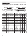
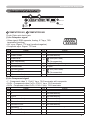
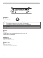
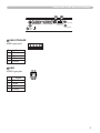
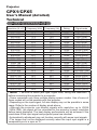
Projector
CPX1/CPX5
User's Manual (detailed)
Technical
Example of computer signal
Resolution (H x V) H. frequency (kHz) V. frequency (Hz)
720 x 400
640 x 480
640 x 480
640 x 480
640 x 480
800 x 600
800 x 600
800 x 600
800 x 600
800 x 600
832 x 624
1024 x 768
1024 x 768
1024 x 768
1024 x 768
1152 x 864
1280 x 960
1280 x 1024
1280 x 1024
1280 x 1024
1600 x 1200
1280 x 768
1400 x 1050
37.9
31.5
37.9
37.5
43.3
35.2
37.9
48.1
46.9
53.7
49.7
48.4
56.5
60.0
68.7
67.5
60.0
64.0
80.0
91.1
75.0
47.7
65.2
85.0
59.9
72.8
75.0
85.0
56.3
60.3
72.2
75.0
85.1
74.5
60.0
70.1
75.0
85.0
75.0
60.0
60.0
75.0
85.0
60.0
60.0
60.0
Rating
Signal mode
VESA
VESA
VESA
VESA
VESA
VESA
VESA
VESA
VESA
VESA
TEXT
VGA (60Hz)
VGA (72Hz)
VGA (75Hz)
VGA (85Hz)
SVGA (56Hz)
SVGA (60Hz)
SVGA (72Hz)
SVGA (75Hz)
SVGA (85Hz)
Mac 16” mode
XGA (60Hz)
XGA (70Hz)
XGA (75Hz)
XGA (85Hz)
1152 x 864 (75Hz)
1280 x 960 (60Hz)
SXGA (60Hz)
SXGA (75Hz)
SXGA (85Hz)
UXGA (60Hz)
W-XGA (60Hz)
SXGA+ (60Hz)
VESA
VESA
VESA
VESA
VESA
VESA
VESA
VESA
VESA
VESA
VESA
VESA
NOTE • Be sure to check jack type, signal level, timing and resolution
before connecting this projector to a computer.
• Some computers may have multiple display screen modes. Use of some of
these modes will not be possible with this projector.
• Depending on the input signal, full-size display may not be possible in some
cases. Refer to the number of display pixels above.
• Although the projector can display signals with resolution up to UXGA
(1600x1200), the signal will be converted to the projector’s panel resolution
before being displayed. The best display performance will be achieved if the
resolutions of the input signal and projector panel are identical.
• Automatically adjustment may not function correctly with some input signals.
• The image may not be displayed correctly when the input sync signal is a
composite sync or a sync on G.
Initial set signals
Initial set signals
The following signals are used for the initial settings. The signal timing of some
computer models may be different. In such case, adjust the items V POSITION
and H POSITION in the IMAGE menu.
Back porch (B)
Front porch (D)
Back porch (b)
Display interval (C)
Data
H. Sync.
Data
V. Sync.
Sync (A)
Computer/ Horizontal signal timing (μs)
Signal
(A)
(B)
(C)
(D)
TEXT
2.0
3.0 20.3 1.0
VGA (60Hz)
3.8
1.9 25.4 0.6
VGA (72Hz)
1.3
4.1 20.3 0.8
VGA (75Hz)
2.0
3.8 20.3 0.5
VGA (85Hz)
1.6
2.2 17.8 1.6
SVGA (56Hz) 2.0
3.6 22.2 0.7
SVGA (60Hz) 3.2
2.2 20.0 1.0
SVGA (72Hz) 2.4
1.3 16.0 1.1
SVGA (75Hz) 1.6
3.2 16.2 0.3
SVGA (85Hz) 1.1
2.7 14.2 0.6
Mac 16" mode 1.1
3.9 14.5 0.6
XGA (60Hz)
2.1
2.5 15.8 0.4
XGA (70Hz)
1.8
1.9 13.7 0.3
XGA (75Hz)
1.2
2.2 13.0 0.2
XGA (85Hz)
1.0
2.2 10.8 0.5
1152 x 864
1.2
2.4 10.7 0.6
(75Hz)
1280 x 960
1.0
2.9
11.9
0.9
(60Hz)
SXGA (60Hz) 1.0
2.3
11.9
0.4
SXGA (75Hz) 1.1
1.8
9.5
0.1
SXGA (85Hz) 1.0
1.4
8.1
0.4
UXGA (60Hz) 1.2
1.9
9.9
0.4
W-XGA (60Hz) 1.7
2.5 16.0 0.8
SXGA+ (60Hz) 1.2
2.0
11.4
0.7
Front porch (d)
Display interval (c)
Sync (a)
Computer/ Vertical signal timing (lines)
Signal
(a)
(b)
(c)
(d)
TEXT
3
42
400
1
VGA (60Hz)
2
33
480
10
VGA (72Hz)
3
28
480
9
VGA (75Hz)
3
16
480
1
VGA (85Hz)
3
25
480
1
SVGA (56Hz)
2
22
600
1
SVGA (60Hz)
4
23
600
1
SVGA (72Hz)
6
23
600
37
SVGA (75Hz)
3
21
600
1
SVGA (85Hz)
3
27
600
1
Mac 16" mode
3
39
624
1
XGA (60Hz)
6
29
768
3
XGA (70Hz)
6
29
768
3
XGA (75Hz)
3
28
768
1
XGA (85Hz)
3
36
768
1
1152 x 864
3
32
864
1
(75Hz)
1280 x 960
3
36
960
1
(60Hz)
SXGA(60Hz)
3
38 1024
1
SXGA (75Hz)
3
38 1024
1
SXGA (85Hz)
3
44 1024
1
UXGA (60Hz)
3
46 1200
1
W-XGA (60Hz)
3
23
768
1
SXGA+ (60Hz)
3
33 1050
1
Connection to the ports
Connection to the ports
A
COMPUTER IN1
S-VIDEO
VIDEO
B
COMPUTER IN2
USB USB STORAGE
DC 5V 0.5A
AUDIO OUT
AUDIO IN
K
A COMPUTOR IN1, B COMPUTOR IN2
D-sub 15pin mini shrink jack
(1) for Computor signal
• Video signal: RGB separate, Analog, 0.7Vp-p, 75Ω
terminated (positive)
• H/V. sync. Signal: TTL level (positive/negative)
• Composite sync. Signal: TTL level
Pin
Signal
1 Video Red
2 Video Green
3 Video Blue
11
6
12
7
1
13
8
2
14
9
3
15
10
4
5
Pin
Signal
10 Ground
11 (No connection)
12
A : SDA (DDC data)
B : (No connection)
4
(No connection)
5
Ground
13 H. sync / Composite sync.
6
Ground Red
14 V. sync.
7
Ground Green
8
Ground Blue
9
(No connection)
15
A : SCL (DDC clock)
B : (No connection)
-
-
(2) for Component signal
•Y : Component video Y, 1.0±0.1 Vp-p, 75 Ω terminator with composite
• CR/PR : Component video CR/PR, 0.7±0.1 Vp-p, 75 Ω terminator
• CB/PB : Component video CR/PR, 0.7±0.1 Vp-p, 75 Ω terminator
Pin
1 CR/PR
2 Y
3 CB/PB
Signal
Pin
Signal
10 Ground
11 (No connection)
12 (No connection)
4
(No connection)
13 (No connection)
5
Ground
14 (No connection)
6
Ground CR/PR
15 (No connection)
7
Ground Y
-
-
8
Ground CB/PB
-
-
9
(No connection)
-
Connection to the ports (continued)
F
C
COMPUTER IN1
D
S-VIDEO
VIDEO
C S-VIDEO
Mini DIN 4pin jack
Pin
1
2
3
4
COMPUTER IN2
USB USB STORAGE
DC 5V 0.5A
E
K
1
3
AUDIO IN
2
4
Signal
Color signal 0.286Vp-p (NTSC, burst), 75Ω terminator
Color signal 0.300Vp-p (PAL/SECAM, burst) 75Ω terminator
Brightness signal, 1.0Vp-p, 75Ω terminator
Ground
Ground
D VIDEO
RCA jack
• System: NTSC, PAL, SECAM, PAL-M, PAL-N, NTSC4.43
• 1.0±0.1Vp-p, 75Ω terminator
E AUDIO IN
Ø3.5 stereo mini jack
• 200 mVrms 47kΩ terminator
F AUDIO
OUT
Ø3.5 stereo mini jack
• 200 mVrms 1kΩ output impedance
AUDIO OUT
Connection to the ports (continued)
H
COMPUTER IN1
COMPUTER IN2
G
USB USB STORAGE
DC 5V 0.5A
AUDIO OUT
AUDIO IN
S-VIDEO
VIDEO
K
G USB STORAGE
USB A type jack
Pin
1
2
3
4
2
1
Signal
+5V
- Data
+ Data
Ground
H USB
USB B type jack
Pin
1
2
3
4
3
4
Signal
+5V
- Data
+ Data
Ground
4
3
1
2